


READ THIS FIRST
MODEL SB1123
***IMPORTANT UPDATE***
SINCE
1906
Applies to Models Mfd. Since 07/21
and Owner’s Manual Revised 04/24
The following change was recently made since the owner’s manual was printed:
• Power Connection content updated.
• Test Run content updated.
• Wiring diagrams updated.
Aside from this information, all other content in the owner’s manual applies and MUST be read and
understood for your own safety. IMPORTANT: Keep this update with the owner’s manual for future
reference.
If you have any further questions about this manual update or the changes made to the machine,
contact our Technical Support at (360) 734-1540 or email www.southbendtools.com.
SINCE
1906
Replaces Page 24 in Owner’s Manual
Power Connection
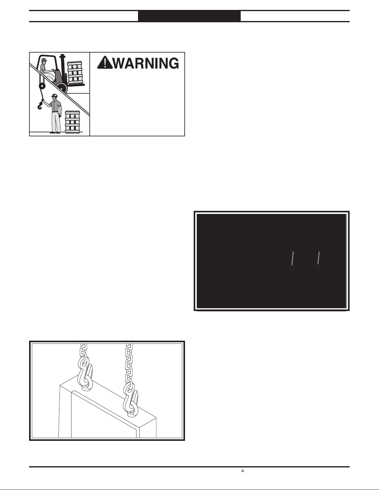
Electrocution or fire
may occur if machine is
ungrounded, incorrectly
connected to power, or
connected to an undersized
circuit. Use a qualified
electrician to ensure a safe
power connection.
Hardwire setups require power supply lines to
be enclosed inside of conduit, which is securely
mounted and constructed in adherence to
applicable electrical codes.
A hardwire setup for this machine must be
equipped with a locking disconnect switch
as a means to disconnect the power during
adjustments or maintenance, which is a typical
requirement for many lock-out/tag-out safety
programs.
Figure 1 shows a simple diagram of a hardwire
setup with a locking disconnect switch between
the power supply and the machine.
Locking
Power Source
Conduit Conduit
Figure Figure 1. Typical hardwire setup with a locking . Typical hardwire setup with a locking
Due to the complexity required for planning,
bending, and installing the conduit necessary for
a code-compliant hardwire setup, an electrician
or other qualified person MUST perform this
type of installation.
Disconnect Switch
disconnect switch.disconnect switch.
Machine
Copyright © August, 2024 by South Bend Tools
WARNING: No portion of this manual may be reproduced without written approval.
#MN23314 Printed in Taiwan

South Bend Tools
Model SB1123
INSTRUCTIONS
Connecting power supply wires to machine
without first disconnecting power supply may
result in serious injury or death.
Mfd. Since 07/21
Revised Test Run Steps
Perform Steps 1–5 of Test Run on Page 25 in the
owner’s manual. Then follow the steps below.
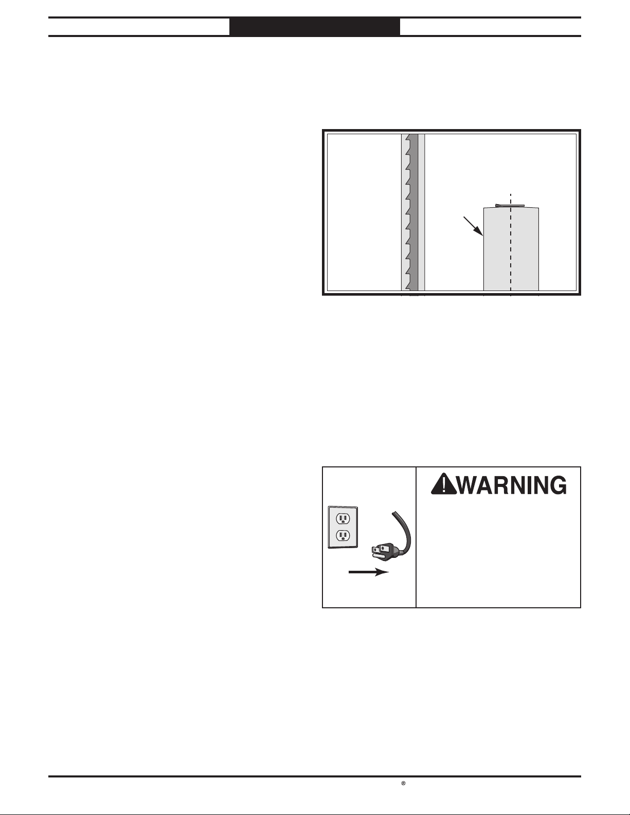
1. Press ON button to turn machine ON, and
observe blade movement.
To connect power supply wires to machine:
1. Remove cover from power supply junction
box.
2. Insert incoming power wires through strain
relief (see Figure 2) at bottom of junction
box, connect wires to terminals shown below,
then install junction box cover.
Note: When using a phase converter, connect
the manufactured power leg or "wild wire"
to the terminal indicated in Figure 2). This
terminal can handle power fluctuation
because it is wired directly to the motor. The
other wires connect to the controls and must
be consistent to prevent damage.
To Magnetic
Switch
T
R
S
E
GND
E
— If blade is moving down toward table,
power supply polarity is correct. Verify
motor starts up and runs smoothly
without any unusual problems or noises,
then proceed to Step 7 in owner’s manual.
— If blade is moving up away from table,
power supply polarity is reversed and
must be corrected. Turn machine OFF and
proceed to Step 2 below.
2. DISCONNECT MACHINE FROM POWER!
3. Open power supply junction box and swap
power supply wires connected to “T” and “S”
terminals (see Figure 3).
To Magnetic
Switch
T
R
S
E
GND
E
= For phase
converter wild
wire (if used)
Figure Figure 2. Terminal box connections.. Terminal box connections.
3. Shut off main power at power source circuit
breaker and attach wires to locking shut-off
switch.
-2-
Incoming
220V/440V
3-PH Power
Swap these
two wires
Incoming
220V/440V
3-PH Power
Figure 3. Power supply wires “T” and “S”.Figure 3. Power supply wires “T” and “S”.
4. Close power supply junction box, connect
machine to power, and repeat Step 1 above.
5. Proceed to Step 7 in owner’s manual.

South Bend Tools
Mfd. Since 07/21 Model SB1123
INSTRUCTIONS
Replaces Page 73 in Owner’s Manual
Wiring Diagram 220V
!
WARNING!
!
220V Mag Switch
SDE M PE-18
SHOCK HAZARD!
Disconnect power
before working on
wiring.
Control Panel
22 21
KEY SWITCH
2
YK 22-1A1BG
14 13
2
2
6
Upper
Wheel Cover
11 12
23 24
T
A
L1/1 L3/5 NO13L2/3
T1/2 T3/6
1/2 3/4 5/6
W
W
V
E
U
MA-18
T2/4
U V
SDE
22
ON BUTTON
YK 22-1A1B
2
SR
NC21
SDE
NC22
NO14
SDE RA-30
18-26A
26
96
RESET
AMP
18
22
98
95
E
Ground
E
T
S
R E
14 13
OFF BUTTON
TAICHUAN
TPB22-S01R
21
NCNC
12
Foot
Brake
2
6
NO
NC
LIMIT SWITCH
CANLI E KL7141
LIMIT
SWITCH
CANLIE
AZDS11
C
U2
GND
U5
Motor 220V
U1
V1
V2
V5
W1
W2
W5
= For phase
converter wild
wire (if used)
T
S
Power Supply
Junction Box
220 VAC 3-Phase
E
R
E
Ground
DISCONNECT SWITCH
(as recommended)
Hot
Hot
-3-

Replaces Page 74 in Owner’s Manual
Wiring Diagram 440V
!
WARNING!
!
440V Mag Switch
SDE M PE-18
SHOCK HAZARD!
Disconnect power
before working on
wiring.
2
Control Panel
22 21
KEY SWITCH
2
YK 22-1A1BG
14 13
2
Upper
Wheel Cover
11 12
6
23 24
T
A
L1/1 L3/5 NO13L2/3
T1/2 T3/6
1/2 3/4 5/6
W
W
UVE
MA-18
T2/4
U V
SDE
22
ON BUTTON
YK 22-1A1B
2
SR
NC21
SDE
NC22
NO14
SDE RA-20
8-12A
RESET
AMP
8
12
10
98
96
95
E
Ground
E
T
S
R E
14 13
OFF BUTTON
TAICHUAN
TPB22-S01R
21
NCNC
12
Foot
Brake
2
6
NO
NC
LIMIT SWITCH
CANLI E KL7141
LIMIT
SWITCH
CANLIE
AZDS11
C
Motor 440V
GND
U2 U5
U1
V2
V1
V5
W2
W1
W5
= For phase
converter wild
wire (if used)
T
S
Power Supply
Junction Box
440V Conversion
3-Phase 440 VAC
E
R
E
Ground
DISCONNECT SWITCH
(as recommended)
Hot
Hot

24" 7 1⁄2 HP BANDSAW
MODEL SB1123
OWNER'S MANUAL
®
South Bend Tools
A Tradition of Excellence
© September, 2021 by South Bend Tools - Revised April, 2024 For Machines Mfd. Since 7/21 (V1.04.24)

We stand behind our machines. If you have any service questions, parts requests or general questions
about your purchase, feel free to contact us.
South Bend Tools
P.O. Box 2027
Bellingham, WA 98227
Phone: (360) 734-1540
Fax: (360) 676-1075 (International)
Fax: (360) 734-1639 (USA Only)
Email: sales@southbendtools.com
For your convenience, any updates to this manual will be available to download free of charge through
our website at:
www.southbendtools.com
Scope of Manual
This manual helps the reader understand the machine, how to prepare it for operation, how to control
it during operation, and how to keep it in good working condition. We assume the reader has a basic
understanding of how to operate this type of machine, but that the reader is not familiar with the
controls and adjustments of this specific model. As with all machinery of this nature, learning the
nuances of operation is a process that happens through training and experience. If you are not an
experienced operator of this type of machinery, read through this entire manual, then learn more
from an experienced operator, schooling, or research before attempting operations. Following this
advice will help you avoid serious personal injury and get the best results from your work.
We've made every effort to be accurate when documenting this machine. However, errors sometimes
happen or the machine design changes after the documentation process—so
exactly match your machine.
contact our
We highly value customer feedback on our manuals. If you have a moment, please share your
experience using this manual. What did you like about it? Is there anything you would change to
make it better? Did it meet your expectations for clarity, professionalism, and ease-of-use?
South Bend Tools
C
P.O. Box 2027
Bellingham, WA 98227
Email: manuals@southbendtools.com
Manual Feedback
If a difference between the manual and machine leaves you in doubt,
customer service for clarification.
the manual may not
/O Technical Documentation Manager
Updates
Customer Service

Table of Contents
INTRODUCTION
Identification
Description of Controls & Components
Product Specifications
SAFETY
Understanding Risks of Machinery
Basic Machine Safety
Additional Bandsaw Safety
PREPARATION
Preparation Overview
Required for Setup
Power Supply Requirements
Converting Voltage to 440V
Unpacking
Inventory
Cleaning & Protecting
Location
Lifting & Moving
Anchoring to Floor
Assembly
Installing Riser Blocks
Dust Collection
Adjustment Overview
Initial Blade Tracking
Power Connection
Test Run
Tensioning Blade
Fine-Tune Tracking
Adjusting Blade Support Bearings
Adjusting Blade Guide Bearings
Aligning Table
Aligning Fence
Calibrating Fence Pointer
Aligning Miter Gauge
OPERATION
Operation Overview
Workpiece Inspection
Setting Upper Blade Guide Height
Blade Selection
Blade Selection Chart
Blade Care & Break-In
Blade Breakage
Changing Blade
Tilting Table
...............................................................................8
............................................... 15
................................................. 17
................................................ 19
................................................ 25
..............................................................2
............................................ 2
................................ 6
................ 8
.................................. 8
........................ 10
.............................................................. 11
............................... 11
................................... 11
....................... 12
....................... 14
.............................................. 15
............................... 16
..................................... 18
................................... 19
.............................. 20
........................................ 21
............................... 22
............................... 22
..................................... 24
...................................... 27
.................................. 28
.............. 29
................. 30
......................................... 32
........................................ 33
.......................... 34
............................... 35
................................................................... 36
.................................. 36
................................ 37
............... 38
........................................ 38
................................ 41
............................... 42
........................................ 42
....................................... 43
........................................... 44
........... 3
Ripping .................................................. 46
Crosscutting
Resawing
Cutting Curves
Stacked Cuts
Using Foot Brake
Blade Lead
ACCESSORIES
MAINTENANCE
Maintenance Schedule............................... 54
Wheel Brushes......................................... 54
Cleaning & Protecting
Lubrication
SERVICE
Tensioning/Replacing V-Belts
Adjusting Wheel Brushes
Adjusting Quick-Release Lever
Adjusting Guide Post Parallelism
Aligning Wheels
Calibrating Table Tilt Scale Pointer
Replacing Brake Shoe
TROUBLESHOOTING
ELECTRICAL
Electrical Safety Instructions
Wiring Diagram 220V
Wiring Diagram 440V
Electrical Component Pictures
PARTS
Main
Table, Tilt, Trunnion & Fence
Motor & Electrical
Motor & Electrical Parts List
Machine Labels
WARRANTY
............................................................................... 77
...................................................... 77
........................................... 47
................................................ 47
........................................ 48
........................................... 48
..................................... 49
.............................................. 49
............................................................. 51
............................................................. 54
............................... 54
............................................. 54
.......................................................................... 57
.................... 57
.......................... 59
................... 59
................ 60
...................................... 63
............. 66
............................... 67
................................................ 68
.................................................................. 72
..................... 72
............................... 73
............................... 74
.................... 75
..................... 80
................................... 82
..................... 83
........................................ 84
.................................................................... 85

South Bend Tools
Model SB1123
Introduction
Identification
Upper Upper
Wheel Wheel
CoverCover
BladeBlade
TensionTension
HandwheelHandwheel
BladeBlade
Tension Tension
IndicatorIndicator
RipRip
FenceFence
Control Control
PanelPanel
INTRODUCTION
BladeBlade
Tracking Tracking
WindowWindow
Guide PostGuide Post
HandwheelHandwheel
GuideGuide
PostPost
BladeBlade
GuidesGuides
Guide PostGuide Post
Lock KnobLock Knob
For Machines Mfd. Since 7/21
Quick-Quick-
ReleaseRelease
BladeBlade
TensionTension
LeverLever
Tracking Tracking
Control Control
KnobKnob
w/Lockw/Lock
LeverLever
MagneticMagnetic
SwitchSwitch
Table TiltTable Tilt
Lock HandleLock Handle
4" Dust Port4" Dust Port
(Side)(Side)
FootFoot
BrakeBrake
Lower WheelLower Wheel
AdjustmentAdjustment
HubHub
4" Dust Port4" Dust Port
Lower Lower
Wheel Wheel
CoverCover
MiterMiter
GaugeGauge
For Your Own Safety, Read Instruction Manual Before Operating Saw.
a) Wear eye protection.
b) Do not remove jammed cutoff pieces until blade has stopped.
c) Maintain proper adjustment of blade tension, blade guides, and thrust bearings.
d) Adjust upper guide to just clear workpiece.
e) Hold workpiece firmly against table.
Table TiltTable Tilt
HandwheelHandwheel
MotorMotor
(Rear)(Rear)
-2-

South Bend Tools
For Machines Mfd. Since 7/21 Model SB1123
INTRODUCTION
Description of Controls & Components
To reduce the risk of
serious injury when using
this machine, read and
understand this entire
manual before beginning any
operations.
Refer to Figures 1–8 and the following
descriptions to become familiar with the basic
controls and components used to operate this
machine.
Control Panel
AA
BB
Guide Post
DD
EE
FF
Figure 2. Guide post controls. Guide post controls.
D. Guide Post Handwheel: Adjusts height of
guide post above workpiece, using a rackand-pinion system.
E. Guide Post w/Scale: Houses upper blade
guides and support bearing, and shields
operator from upper portion of blade.
Adjusts up or down as necessary to position
upper blade guides/support bearing as
close as possible to workpiece for maximum
cutting accuracy and minimum blade
exposure to operator. Scale on side of guide
post indicates height of upper blade guide
above table.
GG
CC
Figure 1. Control panel. Control panel.
A. Master Power Key Switch: Turns incoming
power ON and OFF. Requires key.
B. ON Button: Turns motor ON when pressed.
OFF Button: Turns motor OFF when pressed.
C.
Motor will not start until switch is reset.
Twist clockwise to reset.
Upper Blade Guide & Support Bearing:
F.
Supports blade above workpiece during
operations.
G. Guide Post Lock Knob: Secures guide post
position after adjustment.
-3-

South Bend Tools
Model SB1123
INTRODUCTION
For Machines Mfd. Since 7/21
Table Tilt
JJ
II
HH
KK
Figure 3. Table tilt controls. Table tilt controls.
H. Table Tilt Lock Lever: Secures table tilt
position on trunnion. Must be loosened
before table tilt can be adjusted.
Trunnion w/Table Tilt Scale: Functions as a
I.
tilting base for table. Graduated in degrees
from 5° left – 45° right for setting bevel
angle.
J. Table Tilt Indicator: Shows table tilt angle.
Fence & Miter Gauge
NN
MM
PP
Figure 5. Fence and miter gauge controls. Fence and miter gauge controls.
M. Rip Fence: Used for ripping. Distance from
blade determines width of cut.
N. Miter Gauge Lock Knob: Secures angle
position of miter gauge.
Miter Gauge: Typically used for cross cuts.
O.
Can be adjusted from 0°–60° left or right, and
has stops at 45°L, 0°, and 45°R.
OO
K. Table Tilt Handwheel: Adjusts angle of table
tilt using a rack-and-pinion system.
Foot Brake
LL
Figure 4. Location of foot brake. Location of foot brake.
L. Foot Brake: When pedal is pressed, brake
shoe physically stops blade wheels, and limit
switch electronically turns motor OFF.
P. Fence Lock Handle: Secures fence position.
Lower Wheel Adjustment
QQ
Figure 6. Lower wheel adjustment controls. Lower wheel adjustment controls.
Q. Lower Wheel Adjustment Hub: Adjusts
position of lower wheel to upper wheel if
coplanar adjustments become necessary
(refer to Page 65).
IMPORTANT: After the foot brake is pressed,
the machine can be restarted by pressing the
ON button. The OFF button does not have to
be reset.
-4-
Note: The wheels are factory-set to be
coplanar, so we strongly recommend that
you avoid making adjustments here unless it
becomes absolutely necessary.

South Bend Tools
For Machines Mfd. Since 7/21 Model SB1123
INTRODUCTION
Blade Tension & Tracking
TT
UU
RR
SS
Figure 7. Tension scale and blade tension handwheel. Tension scale and blade tension handwheel.
R. Blade Tension Scale: Displays blade tension
using numbers 0–38. For reference purposes
only—after you have found the proper
tension for the blade installed.
S. Blade Tension Handwheel: Increases/
decreases blade tension (refer to Page 27).
Like all machinery there is potential danger
when operating this machine. Accidents are
frequently caused by lack of familiarity or
failure to pay attention. Use this machine with
respect and caution to decrease the risk of
operator injury. If normal safety precautions are
overlooked or ignored, serious personal injury
may occur.
WW
VV
Figure 8. Tracking window, blade tracking controls, Tracking window, blade tracking controls,
and blade tension quick-release lever.and blade tension quick-release lever.
T. Blade Tracking Window: Allows monitoring/
adjustment of blade tracking without
requiring wheel cover to be open (refer to
Page 22).
Tracking Control Lock Lever: Secures position
U.
of blade tracking control knob.
V. Blade Tension Quick-Release Lever: Quickly
releases blade tension to speed up blade
changes and prevent unnecessary stretching
of blade and wear on saw components when
not in use. Move clockwise to release blade
tension; move counterclockwise to tension
blade; and position downward to partially
tension blade when tracking. To prolong life
of blade, always release blade tension when
saw is not in use.
W. Tracking Control Knob: Adjusts tilt position
of upper wheel to set/control blade tracking
(refer to Page 22).
No list of safety guidelines can be complete.
Every shop environment is different. Always
consider safety first, as it applies to your individual working conditions. Use this and other
machinery with caution and respect. Failure to
do so may result in serious personal injury or
property damage.
-5-

South Bend Tools
Model SB1123
Model SB1123
24" 7-1/2 HP Bandsaw
INTRODUCTION
For Machines Mfd. Since 7/21
Product Specifications
Model SB1123
24" 71/2 HP IndustrialDuty Resaw Bandsaw
Product Dimensions
Weight.............................................................................................................................................................
Width (side-to-side) x Depth (front-to-back) x Height............................................................... 48 x 32 x 83-1/2 in.
Footprint (Length x Width)........................................................................................................... 41-1/2 x 23-1/2 in.
Shipping Dimensions
Type.................................................................................................................................................. Wood Slat Crate
Content..........................................................................................................................................................
Weight.............................................................................................................................................................
Length x Width x Height................................................................................................................... 46 x 28 x 89 in.
Must Ship Upright................................................................................................................................................ Yes
847 lbs.
Machine
948 lbs.
Electrical
Power Requirement................................................................................................... 220V or 440V, 3-Phase, 60 Hz
Prewired Voltage................................................................................................................................................
Full-Load Current Rating................................................................................................
Minimum Circuit Size..................................................................................................... 30A at 220V, 15A at 440V
Connection Type.................................................................................................................... Permanent (Hardwire)
Power Cord Included.............................................................................................................................................. No
Switch Type..............................................................
Voltage Conversion Kit........................................................................................................
Recommended Phase Converter...................................................................................................................... G5845
Motors
Main
Horsepower............................................................................................................................................ 7.5 HP
Phase.................................................................................................................................................... 3-Phase
Amps....................................................................................................................................................
Speed................................................................................................................................................
Type........................................................................................................................................ TEFC Induction
Power Transfer .......................................................................................................................................... Belt
Bearings................................................................................................ Shielded & Permanently Lubricated
Main Specifications
Main Specifications
Bandsaw Size...........................................................................................................................................
Max Cutting Width (Left of Blade)...................................................................................................
Max Cutting Width (Left of Blade) w/Fence.......................................................................................... 23 in.
Max Cutting Height (Resaw Height)...................................................................................................... 16 in.
Blade Speeds.................................................................................................................................... 5100 FPM
Control Panel w/Magnetic Switch Protection & Lockout Key
20A at 220V, 10A at 440V
G440VSB1123 for 440V
220V
20A/10A
1720 RPM
24 in.
24-3/8 in.
-6-

South Bend Tools
For Machines Mfd. Since 7/21 Model SB1123
Blade Information
INTRODUCTION
Standard Blade Length.........................................................................................................................
Blade Length Range...............................................................................................................
Blade Width Range..................................................................................................................... 1/4 - 1-1/2 in.
Type of Blade Guides...................................................................................................... Double Ball Bearing
Guide Post Adjustment Type................................................................................................... Rack & Pinion
Has Quick-Release......................................................................................................................................
Table Information
Table Length......................................................................................................................................
Table Width....................................................................................................................................... 23-5/8 in.
Table Thickness......................................................................................................................................... 2 in.
Table Tilt........................................................................................................................ Left 5 - Right 45 deg.
Table Tilt Adjustment Type.....................................................................................................
Floor-to-Table Height........................................................................................................................
Fence Locking Position............................................................................................................................ Front
Fence is Adjustable for Blade Lead............................................................................................................ Yes
Resaw Fence Attachment Included............................................................................................................. No
Miter Gauge Included.................................................................................................................................
Miter Gauge Information
Miter Angle................................................................................................................................
Miter Gauge Slot Type............................................................................................................................ T-Slot
Miter Gauge Slot Width......................................................................................................................... 3/4 in.
Miter Gauge Slot Height........................................................................................................................ 3/8 in.
181 in.
180 - 181-1/2 in.
Yes
33-1/2 in.
Rack & Pinion
34-1/2 in.
Yes
0 - 60 deg. L/R
Construction Materials
Table....................................................................................................................
Trunnion............................................................................................................................................
Fence.................................................................................................................... Precision-Ground Cast Iron
Base/Stand........................................................................................................................... Pre-Formed Steel
Frame/Body.......................................................................................................................... Pre-Formed Steel
Wheels..............................................................................................................
Tire........................................................................................................................................................
Wheel Cover ........................................................................................................................ Pre-Formed Steel
Paint Type/Finish............................................................................................................. Epoxy/Powder Coat
Other Related Information
Wheel Diameter................................................................................................................................. 24-3/4 in.
Wheel Width........................................................................................................................................
Number of Dust Ports.................................................................................................
Dust Port Size............................................................................................................................................ 4 in.
Compatible Mobile Base.................................................................... D2058A & D2246A, T28000 & T28346
Precision-Ground Cast Iron
Computer-Balanced Cast Iron
2 (Min 400 CFM Each)
Other
Country of Origin ........................................................................................................................................... Taiwan
Warranty ........................................................................................................................................................ 2 Years
Approximate Assembly & Setup Time ................................................................................................... 30 Minutes
Serial Number Location .............................................................................................................................. ID Label
ISO 9001 Factory ................................................................................................................................................. Yes
Cast Iron
Rubber
1-3/4 in.
-7-

South Bend Tools
Model SB1123
Operating all machinery and machining equipment can be dangerous or relatively safe depending on
how it is installed and maintained, and the operator's experience, common sense, risk awareness,
working conditions, and use of personal protective equipment (safety glasses, respirators, etc.).
The owner of this machinery or equipment is ultimately responsible for its safe use. This
responsibility includes proper installation in a safe environment, personnel training and usage
authorization, regular inspection and maintenance, manual availability and comprehension,
application of safety devices, integrity of cutting tools or accessories, and the usage of approved
personal protective equipment by all operators and bystanders.
The manufacturer of this machinery or equipment will not be held liable for injury or property
damage from negligence, improper training, machine modifi cations, or misuse. Failure to read,
understand, and follow the manual and safety labels may result in serious personal injury, including
amputation, broken bones, electrocution, or death.
The signals used in this manual to identify hazard levels are as follows:
Owner’s Manual: All machinery and machining
Trained/Supervised Operators Only: Untrained
SAFETY
SAFETY
For Machines Mfd. Since 7/21
Understanding Risks of Machinery
Death or catastrophic
harm WILL occur.
Death or catastrophic
harm COULD occur.
Moderate injury or fi re
MAY occur.
Machine or property
damage may occur.
Basic Machine Safety
equipment presents serious injury hazards
to untrained users. To reduce the risk of
injury, anyone who uses THIS item MUST
read and understand this entire manual
before starting.
Personal Protective Equipment:
servicing this item may expose the user
to fl ying debris, dust, smoke, dangerous
chemicals, or loud noises. These hazards
can result in eye injury, blindness, longterm respiratory damage, poisoning,
cancer, reproductive harm or hearing loss.
Reduce your risks from these hazards
by wearing approved eye protection,
respirator, gloves, or hearing protection.
Operating or
users can seriously injure themselves
or bystanders. Only allow trained and
properly supervised personnel to operate
this item. Make sure safe operation
instructions are clearly understood. If
electrically powered, use padlocks and
master switches, and remove start switch
keys to prevent unauthorized use or
accidental starting.
Guards/Covers:
moving parts during operation may cause
severe entanglement, impact, cutting,
or crushing injuries. Reduce this risk by
keeping any included guards/covers/doors
installed, fully functional, and positioned
for maximum protection.
Accidental contact with
-8-

South Bend Tools
For Machines Mfd. Since 7/21 Model SB1123
Entanglement: Loose clothing, gloves, neckties,
Chuck Keys or Adjusting Tools: Tools used to
SAFETY
jewelry or long hair may get caught in
moving parts, causing entanglement,
amputation, crushing, or strangulation.
Reduce this risk by removing/securing
these items so they cannot contact moving
parts.
Mental Alertness: Operating this item with
reduced mental alertness increases the
risk of accidental injury. Do not let a
temporary influence or distraction lead
to a permanent disability! Never operate
when under the influence of drugs/alcohol,
when tired, or otherwise distracted.
Safe Environment:
powered equipment in a wet environment
may result in electrocution; operating near
highly fl ammable materials may result in a
fi re or explosion. Only operate this item in
a dry location that is free from fl ammable
materials.
Electrical Connection: With electrically
powered equipment, improper connections
to the power source may result in
electrocution or fire. Always adhere to
all electrical requirements and applicable
codes when connecting to the power
source. Have all work inspected by a
qualified electrician to minimize risk.
Disconnect Power: Adjusting or servicing
electrically powered equipment while it
is connected to the power source greatly
increases the risk of injury from accidental
startup. Always disconnect power
BEFORE any service or adjustments,
including changing blades or other tooling.
Operating electrically
adjust spindles, chucks, or any moving/
rotating parts will become dangerous
projectiles if left in place when the
machine is started. Reduce this risk by
developing the habit of always removing
these tools immediately after using them.
Work Area:
the risks of accidental injury. Only operate
this item in a clean, non-glaring, and welllighted work area.
Properly Functioning Equipment:
maintained, damaged, or malfunctioning
equipment has higher risks of causing
serious personal injury compared to
those that are properly maintained.
To reduce this risk, always maintain
this item to the highest standards and
promptly repair/service a damaged or
malfunctioning component. Always follow
the maintenance instructions included in
this documentation.
Unattended Operation:
equipment that is left unattended while
running cannot be controlled and is
dangerous to bystanders. Always turn the
power OFF before walking away.
Health Hazards: Certain cutting fluids and
lubricants, or dust/smoke created when
cutting, may contain chemicals known to
the State of California to cause cancer,
respiratory problems, birth defects,
or other reproductive harm. Minimize
exposure to these chemicals by wearing
approved personal protective equipment
and operating in a well ventilated area.
Clutter and dark shadows increase
Poorly
Electrically powered
Secure Workpiece/Tooling:
cutting tools, or rotating spindles can
become dangerous projectiles if not
secured or if they hit another object during
operation. Reduce the risk of this hazard
by verifying that all fastening devices are
properly secured and items attached to
spindles have enough clearance to safely
rotate.
Loose workpieces,
Diffi cult Operations:
operations with which you are unfamiliar
increases the risk of injury. If you
experience difficulties performing the
intended operation, STOP! Seek an
alternative method to accomplish the
same task, ask a qualified expert how the
operation should be performed, or contact
our Technical Support for assistance.
Attempting difficult
-9-

South Bend Tools
Model SB1123
SAFETY
For Machines Mfd. Since 7/21
Additional Bandsaw Safety
Serious cuts, amputation, or death can occur from contact with the moving saw blade during
operation or if blade breakage occurs. Serious injury or death can also occur from getting fingers,
hair, or clothing entangled in moving parts if the machine is operated while the doors are open. To
reduce this risk, anyone operating this machine MUST completely heed the hazards and warnings
below.
Hand Placement. Placing hands or fingers
in line with blade or too close to blade
during operation may result in serious
injury if hands slip or workpiece moves
unexpectedly. Do not position fingers or
hands in line with blade, and never reach
under table while blade is moving.
Small/Narrow Workpieces. If hands slip during
a cut while holding small workpieces
with fingers, serious personal injury or
amputation may occur. Always support/
feed small or narrow workpieces with push
sticks, push blocks, jig, vise, or some type
of clamping fixture.
Blade Speed. Cutting workpiece before blade
is at full speed could cause blade to grab
workpiece and pull hands into blade. Allow
blade to reach full speed before starting
cut. DO NOT start machine with workpiece
contacting blade.
Feed Rate. To avoid risk of workpiece slipping
and causing operator injury, always feed
stock evenly and smoothly. Do not force
workpiece through the cut.
Blade Condition. Dull blades require more
effort to perform cut, increasing risk of
accidents. Do not operate with dirty, dull,
cracked or badly worn blades. Inspect
blades for cracks and missing teeth before
each use. Always maintain proper blade
tension and tracking while operating.
Clearing Jams and Cutoffs. Always stop bandsaw
and disconnect power before clearing scrap
pieces that get stuck between blade and
table insert. Use brush or push stick, not
hands, to clear cutoff scraps or clean chips
from table.
Blade Control. To avoid risk of injury due to
blade contact, always allow blade to stop on
its own. DO NOT try to stop or slow blade
with your hand or the workpiece.
Guards/Covers. Blade guards and covers protect
operator from the moving bandsaw blade.
The wheel covers protect operator from
getting entangled with rotating wheels
or other moving parts. ONLY operate
this bandsaw with blade guard in proper
position and wheel covers completely
closed.
Upper Blade Guide Support. To minimize
exposure of operator to blade and provide
maximum blade support while cutting,
keep upper blade guides adjusted to just
clear workpiece (approximately
above workpiece).
Cutting Techniques. To avoid blade getting
pulled off wheels or accidentally breaking
and striking operator, always turn bandsaw
OFF and wait for blade to come to a
complete stop before backing workpiece
out of blade. DO NOT back workpiece away
from blade while bandsaw is running. DO
NOT force or twist blade while cutting,
especially when sawing small curves. This
could result in blade damage or breakage.
Workpiece Support. To maintain maximum
control and reduce risk of blade contact/
breakage, always ensure adequate support
of long/large workpieces. Always keep
workpiece flat and firm against table/fence
when cutting to avoid loss of control. If
necessary, use a jig or other work-holding
device.
1
⁄8"–1⁄4"
-10 -

South Bend Tools
For Machines Mfd. Since 7/21 Model SB1123
PREPARATION
PREPARATION
Preparation Overview Required for Setup
The purpose of the preparation section is to help
you prepare your machine for operation. The list
below outlines the basic process. Specific steps
for each of these points will be covered in detail
later in this section.
The typical preparation process is as follows:
1. Unpack the machine and inventory the
contents of the box/crate.
Clean the machine and its components.
2.
3. Identify an acceptable location for the
machine and move it to that location.
Level the machine and either bolt it to the
4.
floor or place it on mounts.
Assemble the loose components and make
5.
any necessary adjustments or inspections to
ensure the machine is ready for operation.
Connect the machine to the power source.
6.
7. Test run the machine to make sure it
functions properly and is ready for
operation.
Serious personal injury could occur if
you connect the machine to power before
completing the setup process. DO NOT
connect power until instructed to do so later
in this manual.
The items listed below are required to
successfully set up and prepare this machine for
operation.
For Lifting
• A forklift or other power lifting device rated
for the weight of the machine.
• 1x4 and 2x4 blocks.
• Lifting strap w/safety hooks or chain (rated
for at least 1000 lbs.)
For Power Connection
• A power source that meets the minimum
circuit requirements for this machine. (Refer
to the Power Supply Requirements section
for details.)
• A qualified electrician to ensure a safe and
code-compliant connection to the power
source.
For Assembly
• Safety Glasses
• Cleaner/Degreaser
• Disposable Shop Rags/Gloves
• Straightedge 36"
• Floor Mounting Hardware (As Needed)
• Fine Ruler
• Feeler Gauge 0.016"
• Dust Collection System
• Dust Hoses 4" (x2)
• Hose Clamps 4" (x2)
• Machinist's Square
• Phillips Head Screwdriver #2
• Hex Wrench 8mm
-11-

South Bend Tools
Model SB1123
Before installing the machine, consider the
availability and proximity of the required power
supply circuit. If an existing circuit does not
meet the requirements for this machine, a new
circuit must be installed.
To minimize the risk of electrocution, fire,
or equipment damage, installation work and
electrical wiring must be done by a
or qualified service personnel in accordance with
applicable electrical codes and safety standards.
The full-load current rating is the amperage
a machine draws at 100% of the rated output
power. On machines with multiple motors, this is
the amperage drawn by the largest motor or sum
of all motors and electrical devices that might
operate at one time during normal operations.
The full-load current is not the maximum
amount of amps that the machine will draw. If
the machine is overloaded, it will draw additional
amps beyond the full-load rating.
If the machine is overloaded for a sufficient
length of time, damage, overheating, or fire may
result—especially if connected to an undersized
circuit. To reduce the risk of these hazards,
avoid overloading the machine during operation
and make sure it is connected to a power supply
circuit that meets the requirements in the
following section.
Note: The circuit requirements in this manual
are for
machine will be running at a time. If this
machine will be connected to a shared circuit
where multiple machines will be running at the
same time, consult a qualified electrician to
ensure the circuit is properly sized.
A power supply circuit includes all electrical
equipment between the main breaker box or fuse
panel in your building and the incoming power
connections inside the machine. This circuit
must be safely sized to handle the full-load
current that may be drawn from the machine for
an extended period of time. (If this machine is
connected to a circuit protected by fuses, use a
time delay fuse marked D.)
This machine must be grounded! In the event of
certain types of
grounding provides a path of least resistance
for electric current
electric shock.
Improper connection of the equipmentgrounding wire can result in a risk of electric
shock. The wire with green insulation (with
or without yellow stripes) is the equipmentgrounding wire. If repair or replacement of the
power cord or plug is necessary, do not connect
the equipment-grounding wire to a live (current
carrying) terminal.
Check with an electrician or qualifi ed service
personnel if you do not understand these
grounding requirements, or if you are in doubt
about whether the tool is properly grounded.
If you ever notice that a cord or plug is damaged
or worn, disconnect it from power, and
immediately replace it with a new one.
PREPARATION
For Machines Mfd. Since 7/21
Power Supply Requirements
Availability
Electrocution or fire may
occur if machine is not
correctly grounded and
attached to the power
supply. Use a qualified
electrician to ensure a safe
power connection.
n electrician
Circuit Information
For your own safety and protection of property,
consult an electrician if you are unsure about
wiring practices or applicable electrical codes.
a dedicated circuit—where only one
Grounding Requirements
Full-Load Current Rating
Full-Load Rating at 220V ...................... 20 Amps
Full-Load Rating at 440V ...................... 10 Amps
-12 -
malfunctions or breakdowns,
in order to reduce the risk of

South Bend Tools
For Machines Mfd. Since 7/21 Model SB1123
This machine can be converted to operate on a
44
Voltage
Conversion
.
The intended
ground and meet the following requirements:
Serious injury could occur if you connect
the machine to power before completing the
This machine is prewired to operate on a power
supply circuit that has a verified ground and
meets the following requirements:
PREPARATION
Phase Converters
DO NOT use a static phase converter to create
3-phase power—it can quickly decrease the life
of electrical components on this machine. If you
must use a phase converter, only use a rotary
phase converter.
setup process. DO NOT connect to power until
instructed later in this manual.
Circuit Requirements for 220V
Nominal Voltage ...................... 220V/230V/240V
............................................................. 60 Hz
Cycle
Phase
Circuit Rating
Connection
.........................................................3-Phase
......................................... 30 Amps
..............Hardwire with Locking Switch
Circuit Requirements for 440V
0V power supply. To do this, follow the
instructions included in this manual
440V circuit must have a verified
Connection Type
A permanently connected (hardwired) power
supply is typically installed with wires running
through mounted and secured conduit. A
disconnecting means, such as a locking switch
(see Figure 9), must be provided to allow the
machine to be disconnected (isolated) from the
power supply when required. This installation
must be performed by an electrician in
accordance with all applicable electrical codes
and ordinances.
LOCKING
DISCONNECT SWITCH
Power Source
Conduit
Ground Ground
Figure Figure 9. Typical setup of a permanently connected . Typical setup of a permanently connected
machine.machine.
Conduit
Machine
Extension Cords
Since this machine must be permanently
connected to the power supply, an extension cord
cannot be used.
Nominal Voltage ................................ 440V/480V
............................................................. 60 Hz
Cycle
Phase
Circuit Rating
Connection
.........................................................3-Phase
......................................... 15 Amps
..............Hardwire with Locking Switch
-13 -

South Bend Tools
Model SB1123
PREPARATION
For Machines Mfd. Since 7/21
Converting Voltage to 440V
The Model SB1123 can be converted to 440V
operation. This conversion consists of: 1)
Disconnecting the saw from power, 2) replacing
the magnetic switch, 3) rewiring the motor for
440V operation.
All wiring changes must be inspected by a
qualified electrician or service personnel before
the saw is connected to the power source. If,
at any time during this procedure you need
assistance, call Grizzly Tech Support at (570)
546-9663.
Items Needed Qty
Phillips Head Screwdriver ............................ 1
440V Magnetic Switch (Part PSB1123453)
Wrench or Socket 6mm................................. 1
To convert SB1123 to 440V operation:
1. DISCONNECT MACHINE FROM POWER!
...... 1
2. Remove 220V magnetic switch from machine
column (see Figure 10) and replace with
440V magnetic switch (refer to wiring
diagram on Page 74).
MagneticMagnetic
SwitchSwitch
Figure Figure 10. Location of magnetic switch.. Location of magnetic switch.
3. Rewire motor for 440V operation (refer to
wiring diagram on Page 74).
Note: If the diagram included on the motor
conflicts with the one in this manual, the
motor may have changed since the manual
was printed. Use the diagram provided on
the motor.
-14-

South Bend Tools
For Machines Mfd. Since 7/21 Model SB1123
This item was carefully packaged to prevent
damage during transport. If you discover any
damage, please immediately call Customer
Service at
need to file a freight claim, so save the containers
and all packing materials for possible inspection
by the carrier or its agent.
PREPARATION
Unpacking
(360) 734-1540 for advice. You may
Inventory
Box 1 (Figure 11) Qty
A. Bandsaw (Not Shown) ............................ 1
Fence ..................................................1
B.
Fence Rail ............................................ 1
C.
Miter Gauge .........................................1
D.
Open-Ends Wrench 10/13mm .................. 1
E.
Open-Ends Wrench 17/19mm .................. 1
F.
Hex Wrench 6mm ..................................1
G.
Hex Wrench 5mm ..................................1
H.
Eye Bolts M12-1.75 x 22 .........................2
I.
Guide Post Handwheel ............................ 1
J.
Box 2 (Figure 12) Qty
K. Riser Blocks ......................................... 2
Hex Bolts M12-1.75 x 100 ....................... 4
L.
Flat Washers 12mm ............................... 4
M.
Lock Washers 12mm ..............................4
N.
KK
LL
MM
NN
Figure Figure 12. Box 2 inventory.. Box 2 inventory.
If you cannot find an item on this list, carefully
check around/inside the machine and
packaging materials. Often, these items get
lost in packing materials while unpacking or
they are pre-installed at the factory.
BB
JJ
Figure Figure 11. Box 1 inventory.. Box 1 inventory.
II
HH GG
CC
DD
EE
FF
-15 -

South Bend Tools
Model SB1123
The unpainted surfaces are coated
with a heavy-duty rust preventative that
prevents corrosion during shipment and
The benefi t of this rust preventative is that it
works very well. The downside is that it
time-consuming
Be patient and do a careful job when
removing the rust preventative
spend doing this will reward you with smooth
sliding parts and a better appreciation for the
proper care of
Although there are many ways to successfully
remove the rust preventative, the
process works well in most situations
Before cleaning, gather the following:
• Disposable
• Cleaner/degreaser
• Safety glasses & disposable gloves
Note:
WD•40 can be used to remove rust preventative.
Before using these products, though, test them
on an inconspicuous area of a painted surface to
make sure they will not damage it.
GAS
Order online at
Call 1-800-523-477
PREPARATION
Cleaning & Protecting
For Machines Mfd. Since 7/21
at the factory
to thoroughly remove.
degreasers work extremely well and they
have non-toxic fumes)
Automotive degreasers, mineral spirits, or
the unpainted surfaces.
rags
(certain citrus-based
. The time you
following
storage.
can be
cleaning and
-
.
Avoid chlorine-based solvents, such as
acetone or brake parts cleaner that may
damage painted surfaces. Always follow the
manufacturer’s instructions when using any
type of cleaning product.
Basic steps for removing rust preventative:
1. Put on safety glasses and disposable gloves.
2. Coat all surfaces that have rust preventative
with a liberal amount of your cleaner or
degreaser and let them soak for a few
minutes.
3. Wipe off the surfaces. If your cleaner or
degreaser is effective, the rust preventative
will wipe off easily.
Note: To clean off thick coats of rust
preventative on fl at surfaces, such as beds
or tables, use a PLASTIC paint scraper to
scrape off the majority of the coating before
wiping it off with your rag. (Do not use a
metal scraper or it may scratch the surface.)
4. Repeat Steps 2–3 as necessary until clean,
then coat all unpainted surfaces with a
quality metal protectant or light oil to
prevent rust.
-16-
Gasoline and petroleum
products have low flash
points and can explode
or cause fire if used for
cleaning. Avoid using these
products to remove rust
preventative.
Many cleaning solvents are
toxic if inhaled. Minimize
your risk by only using
these products in a well
ventilated area.
T23692—Orange Power Degreaser
A great product for removing the waxy shipping
grease from the non-painted parts of the
machine during clean up.
www.grizzly.com
OR
7
Figure Figure 13.. T23692 Orange Power Degreaser.

South Bend Tools
For Machines Mfd. Since 7/21 Model SB1123
Weight Load
equipment that may be installed on the machine,
Physical Environment
The physical environment where your machine
is operated is important for safe operation and
longevity of
machine in a dry environment that is free from
excessive moisture, hazardous
chemicals, airborne abrasives, or extreme
conditions. Extreme conditions for this type
of machinery are generally those where the
ambient temperature
104°F; the relative humidity
of
is subject to vibration, shocks, or bumps.
Electrical Installation
Place this machine near an existing power
source. Make sure all power cords are protected
from traffic, material handling, moisture,
chemicals, or other hazards. Make sure to leave
access to a means of disconnecting the power
source or engaging a lockout/tagout device.
Lighting
Lighting around the machine must be adequate
enough to perform operations safely. Shadows,
glare, or strobe effects that may distract or
impede the operator must be eliminated.
PREPARATION
Location
Physical Environment
Electrical Installation
Lighting
Weight Load
Space Allocation
20–95% (non-condensing); or the environment
parts. For best results, operate this
or flammable
is outside the range of 41°–
is outside the range
Refer to the Machine Specifications for the
weight of your machine. Make sure that the
surface upon which the machine is placed will
bear the weight of the machine, additional
and the heaviest workpiece that will be used.
Additionally, consider the weight of the operator
and any dynamic loading that may occur when
operating the machine.
Space Allocation
Consider the largest size of workpiece that will
be processed through this machine and provide
enough space around the machine for adequate
operator material handling or the installation
of auxiliary equipment. With permanent
installations, leave enough space around
the machine to open or remove doors/covers
as required by the maintenance and service
described in this manual.
= Electrical
Connection
Children or untrained
people may be seriously
48"
Figure 14. Clearances.Figure 14. Clearances.
injured by this machine.
Only install in an access
restricted location.
Keep Workpiece
Unloading Area
Unobstructed
32"
Keep Workpiece
Loading Area
Unobstructed
-17-
South Bend Tools
Model SB1123
PREPARATION
For Machines Mfd. Since 7/21
Lifting & Moving
This machine and its
parts are heavy! Serious
personal injury may occur
if safe moving methods are
not used. To reduce the
risk of a lifting or dropping
injury, ask others for help
and use power equipment.
Special care should be taken when moving
this bandsaw. To reduce your risk of injury or
accidental damage, use one of the following
methods to life or move the bandsaw.
If you plan to use the included riser blocks to
increase the working height of the machine, we
recommend installing them while the machine is
lifted off the pallet, following Step 3 below. For
details, see Installing Riser Blocks on Page 20.
4. Remove pallet, then slowly lower bandsaw
into position.
Using Forklift & Wood Blocks
1. Use forklift to move crate to prepared
location, then remove crate from shipping
pallet.
Unbolt bandsaw from pallet.
2.
3. Carefully place forklift forks under bandsaw
head. Insert a 1x4 block between head and
left fork, and a 2x4 block between head and
right fork so bandsaw remains relatively
level when lifted, as shown in Figure 16.
Note: If you are concerned about your forklift
forks hitting the tension handwheel, remove
handwheel before positioning forks, then
re-install it after placing bandsaw in final
location.
Using Forklift & Eye Bolts
1. Use forklift to move crate to a prepared
location, then remove crate from shipping
pallet.
Unbolt bandsaw from pallet.
2.
3. Install eye bolts. Make sure they are
threaded all the way in, then place lifting
hooks through eye bolts (see Figure 15) and
lift bandsaw slowly with forklift just enough
to clear pallet.
2x42x4 1x41x4
Figure Figure 16. Example of lifting bandsaw with forklift and . Example of lifting bandsaw with forklift and
using wood blocks on forks.using wood blocks on forks.
4. Lift bandsaw off of pallet, remove pallet,
then slowly lower bandsaw into position.
Figure 15. Lifting locations.Figure 15. Lifting locations.
-18 -

South Bend Tools
For Machines Mfd. Since 7/21 Model SB1123
PREPARATION
AssemblyAnchoring to Floor
Number of Mounting Holes ..........................................4
Diameter of Mounting Hardware
Anchoring machine to the floor prevents tipping
or shifting that may occur during operation with
large/heavy workpieces.
If machine is installed in a commercial or
workplace setting, or if it is permanently
connected (hardwired) to the power supply, local
codes may require that it be anchored to the floor.
.............................1⁄2"
Mounting to Concrete Floors
Lag shield anchors with lag screws (see below)are
a popular way to anchor machinery to a concrete
floor, because the anchors sit flush with the floor
surface, making it easy to unbolt and move the
machine later, if needed. However, anytime local
codes apply, you MUST follow the anchoring
methodology specified by the code.
The machine must be fully assembled before it
can be operated. Before beginning the assembly
process, refer to Required for Setup and gather
all the items listed. To ensure the assembly
process goes smoothly, first clean any parts
that are covered or coated in heavy-duty rust
preventative (if applicable).
To assemble bandsaw:
1. Install fence rail on table using (3) pre-
installed hex bolts, lock washers, and flat
washers (see Figure 18).
x 3
Lag Screw
Flat Washer
Machine Base
Lag Shield Anchor
Concrete
Drilled Hole
Figure Figure 17. Popular method for anchoring machinery to . Popular method for anchoring machinery to
a concrete floor.a concrete floor.
Figure Figure 18. Fence rail installed.. Fence rail installed.
-19 -

South Bend Tools
Model SB1123
PREPARATION
For Machines Mfd. Since 7/21
2. Slide guide post handwheel (see Figure 19)
onto shaft and secure with pre-installed cap
screw.
Guide Post Guide Post
HandwheelHandwheel
Figure Figure 19. Guide post handwheel installed.. Guide post handwheel installed.
Pull fence handle up and place fence on rail
3.
(see Figure 20).
Push fence handle down to lock fence in place
4.
(see Figure 20).
Installing Riser Blocks
The Model SB1123 comes with riser blocks that
can be used to increase the floor-to-table height
from 33" to 34 1⁄2".
Figure Figure 21. Riser block components.. Riser block components.
To install riser blocks:
1. Lift bandsaw with forklift or other power
equipment.
FenceFence
HandleHandle
RailRail
Figure Figure 20. Fence installed on table.. Fence installed on table.
Insert (4) hex bolts, lock washers, and flat
2.
washers (see Figure 22) through holes in base
of machine.
Align hex bolts with threaded holes in riser
3.
blocks (see Figure 22) and securely tighten.
Note: Riser blocks are equipped with tabs for
securing the bandsaw to the floor to maximize
stability.
x 4
-20 -
Figure Figure 22. Riser block location and installation . Riser block location and installation
hardware.hardware.

South Bend Tools
For Machines Mfd. Since 7/21 Model SB1123
PREPARATION
Dust Collection
This machine creates a lot of wood chips/
dust during operation. Breathing airborne dust
on a regular basis can result in permanent
respiratory illness. Reduce your risk by
wearing a respirator and capturing the dust
with a dust-collection system.
Minimum CFM at each Dust Port: 400 CFM
Do not confuse this CFM recommendation with
the rating of the dust collector. To determine
the CFM at the dust port, you must consider
these variables: (1) CFM rating of the dust
collector, (2) hose type and length between the
dust collector and the machine, (3) number of
branches or wyes, and (4) amount of other open
lines throughout the system. Explaining how
to calculate these variables is beyond the scope
of this manual. Consult an expert or purchase
a good dust collection "how-to" book.
To connect dust collection system to
machine:
1. Fit a 4" dust hose over each dust port, and
secure them in place with hose clamps (see
Figure 23).
Note: For best results, connect free ends of
hoses to a 4" Y-fitting and secure with hose
clamps, then connect fitting to your dust
collection system. See Accessories, beginning
on Page 51, for more information.
Tug hoses to make sure they do not come off.
2.
Note: A tight fit is necessary for proper
performance.
Figure Figure 23. Dust hoses attached.. Dust hoses attached.
-21-
South Bend Tools
Model SB1123
PREPARATION
For Machines Mfd. Since 7/21
Adjustment Overview
The bandsaw is one of the most versatile
woodworking machines. However, it has multiple
components that must be properly adjusted for
the best cutting results.
For practical and safety reasons, some
adjustments and test operations must be
performed before performing other necessary
adjustments. Below is an overview of all the
adjustments and the order in which they should
be performed:
Initial Blade Tracking
1.
Power Connection
2.
3. Test Run
Tensioning Blade
4.
Fine-Tune Tracking
5.
Adjusting Blade Support Bearings
6.
Adjusting Blade Guide Bearings
7.
8. Aligning Table
Aligning Fence
9.
Calibrating Fence Pointer
10.
Aligning Miter Gauge
11.
Bandsaw wheels are either flat or crowned and
both shapes track differently. This bandsaw has
crowned wheels. As the wheels spin, a properly
tracking blade naturally tracks at the center of
the wheel (see Figure 24).
PROPER TRACKING
Blade Centered
on Wheel
Blade
Centered
on Wheel
Figure 24. Blade centered on crown of wheel. Blade centered on crown of wheel.
Blade tracking is primarily affected by the tilt
of the upper wheel, known as “center tracking.”
However, the alignment of both wheels plays an
important part as well (see Aligning Wheels on
Page 63 for more details).
Wheel
Initial Blade Tracking
"Tracking" refers to how the blade rides on the
bandsaw wheels. Proper tracking is important
for maintaining bandsaw adjustments, achieving
correct blade tension, and cutting accurately.
Improper tracking reduces cutting accuracy,
causes excess vibrations, and places stress on the
blade and other bandsaw components. The shape
of the wheels and the orientation of the wheels
in relation to each other determine how the blade
tracks.
The wheels on this bandsaw were aligned at the
factory, so center tracking is the only adjustment
that needs to be checked/performed when the
saw is new.
Serious personal injury
!
can occur if the machine
starts while your hand is
touching the bandsaw wheel
during tracking adjustments.
Disconnect power from the
bandsaw before performing
blade tracking adjustments.
-22-

South Bend Tools
For Machines Mfd. Since 7/21 Model SB1123
To adjust blade tracking:
1. DISCONNECT MACHINE FROM POWER!
Adjust upper and lower blade guides
2.
away from blade, and raise upper guides
approximately
2
⁄3 of the way up (see
PREPARATION
Loosen tracking control lock lever on back of
5.
bandsaw (see Figure 27).
Rotate upper wheel by hand several times
6.
and watch how blade rides on wheel (see
Figure 27).
Adjusting Blade Guide Bearings on Page 30
for detailed instructions).
— If the blade consistently rides in the
center of the upper wheel, it is tracking
Note: After test run is successfully
completed, you will be instructed on how
properly and no adjustments are
necessary; proceed to Step 8.
to more accurately tension the blade for
optimum results.
— If the blade does not consistently ride in
the center of the upper wheel, it is not
Rotate blade tension quick-release lever to
3.
tracking properly; proceed to Step 7.
PARTIAL TENSION setting (see Figure 25).
Adjust tracking control knob (see Figure
7.
27) in small amounts and continue to rotate
Blade TensionBlade Tension
Quick-Release LeverQuick-Release Lever
upper wheel by hand at the same time until
blade consistently rides in center of wheel.
Quick-ReleaseQuick-Release
Lever LabelLever Label
Figure 25. Blade tension quick-release lever rotated Blade tension quick-release lever rotated
to PARTIAL TENSION setting.to PARTIAL TENSION setting.
4. Rotate blade tension handwheel (see Figure
26) until blade tension matches mark on
blade tension scale for appropriate blade
thickness. Rotate handwheel clockwise to
increase blade tension. Rotate handwheel
counterclockwise to decrease blade tension.
Blade Tension Blade Tension
ScaleScale
BladeBladeWheelWheel
BladeBlade
Tracking Tracking
WindowWindow
Figure 27. Blade tracking controls. Blade tracking controls.
Tighten tracking control lock lever.
8.
Tracking ControlTracking Control
Lock Lever Lock Lever
TrackingTracking
ControlControl
KnobKnob
Note: For the best performance from your
saw, regularly maintain proper tracking of
the blade. Fine-tune tracking must be done
with the bandsaw turned ON. Refer to Page
28 for more information.
Figure 26. Blade tensioning controls. Blade tensioning controls.
Blade Tension Blade Tension
HandwheelHandwheel
-23-

South Bend Tools
Model SB1123
PREPARATION
Power Connection
Electrocution or fire
may occur if machine is
ungrounded, incorrectly
connected to power, or
connected to an undersized
circuit. Use a qualified
electrician to ensure a safe
power connection.
Hardwire setups require power supply lines to
be enclosed inside of conduit, which is securely
mounted and constructed in adherence to
applicable electrical codes.
A hardwire setup for this machine must be
equipped with a locking disconnect switch
as a means to disconnect the power during
adjustments or maintenance, which is a typical
requirement for many lock-out/tag-out safety
programs.
Figure 28 shows a simple diagram of a hardwire
setup with a locking disconnect switch between
the power supply and the machine.
Locking
Power Source
Disconnect Switch
Machine
For Machines Mfd. Since 7/21
Connecting power supply wires to machine
without first disconnecting power supply may
result in serious injury or death.
To connect power supply wires to machine:
1. Remove cover from power supply junction
box.
Insert incoming power wires through strain
2.
relief (see Figure 29) at bottom of junction
box, connect wires to terminals shown below,
then install junction box cover.
Note: When using a phase converter, connect
the manufactured power leg or "wild wire"
to the terminal indicated in Figure 29).
This terminal can handle power fluctuation
because it is wired directly to the motor. The
other wires connect to the controls and must
be consistent to prevent damage.
To Magnetic
Switch
T
R
S
E
E
Ground
Conduit Conduit
Figure Figure 28. Typical hardwire setup with a locking . Typical hardwire setup with a locking
disconnect switch.disconnect switch.
Due to the complexity required for planning,
bending, and installing the conduit necessary for
a code-compliant hardwire setup, an electrician
or other qualified person MUST perform this
type of installation.
-24-
= For phase
converter wild
wire (if used)
Figure Figure 29. Terminal box connections.. Terminal box connections.
Shut off main power at power source circuit
3.
Incoming
220V/440V
3-PH Power
breaker and attach wires to locking shut-off
switch.

South Bend Tools
For Machines Mfd. Since 7/21 Model SB1123
PREPARATION
Test Run
After all preparation steps have been completed,
the machine and its safety features must be
tested to ensure correct operation. If you
discover a problem with the operation of the
machine or its safety components, do not operate
it further until you have resolved the problem.
Note: Refer to Troubleshooting on Page 68
for solutions to common problems. If you need
additional help, contact our Tech Support at
(360) 734-1540.
The test run consists of verifying the following:
• Motor powers up and runs correctly.
• OFF button works correctly.
• Foot brake limit switch works correctly.
• Upper door limit switch works correctly.
4. Insert key into Master Power Key Switch,
then rotate switch to "1" position (see
Figure 30). This turns incoming power ON.
Twist OFF button clockwise until it springs
5.
out (see Figure 30). This resets switch so
machine can start.
Press ON button (see Figure 30) to turn
6.
machine ON. Verify motor starts up and
runs smoothly without any unusual problems
or noises.
Master Power Master Power
Key SwitchKey Switch
ON ButtonON Button
OFF Button
Serious injury or death can result from using
this machine BEFORE understanding its
controls and related safety information. DO
NOT operate, or allow others to operate,
machine until the information is understood.
DO NOT start machine until all preceding
setup instructions have been performed.
Operating an improperly set up machine may
result in malfunction or unexpected results
that can lead to serious injury, death, or
machine/property damage.
To test run machine:
1. Clear all setup tools away from machine.
2. Press OFF button.
3. Connect machine to power source.
Figure 30. Location of power controls for turning Location of power controls for turning
machine machine ONON and and OFFOFF..
Press OFF button to turn machine OFF.
7.
WITHOUT resetting OFF button, try to start
8.
machine by pressing ON button. Machine
should not start.
— If the machine does not start, the safety
feature of the OFF button is working
correctly.
— If the machine does start, immediately
turn it OFF, disconnect power, and
contact customer service for assistance.
The safety feature of the OFF button
is NOT working properly and must
be replaced before further using the
machine.
-25-

South Bend Tools
Model SB1123
PREPARATION
For Machines Mfd. Since 7/21
9. Repeat Steps 5–6 to turn machine ON.
Allow motor to reach full speed, then step
10.
on foot brake pedal (see Figure 31). Blade
should stop moving and motor should turn
OFF.
Foot Brake Foot Brake
PedalPedal
Figure 31. Location of foot brake pedal. Location of foot brake pedal.
— If the blade stops moving and the motor
turns OFF, the foot brake feature is
working correctly.
— If the blade does not stop moving, or
the motor does not turn OFF, the foot
brake feature is not working correctly.
Turn machine OFF, disconnect power
immediately, and contact customer
service for assistance.
11. Make sure blade has fully stopped, open
upper wheel cover a few inches to reveal limit
switch (see Figure 32), then turn bandsaw
ON.
Limit Limit
SwitchSwitch
Figure Figure 32. Location of limit switch in upper wheel . Location of limit switch in upper wheel
cover.cover.
— If the bandsaw does not start, then the
upper wheel cover limit switch is working
correctly. Test run is complete.
— If the bandsaw starts, the upper wheel
cover limit switch is not working
correctly. Turn machine OFF, disconnect
power immediately, and contact customer
service for assistance.
-26-

South Bend Tools
For Machines Mfd. Since 7/21 Model SB1123
PREPARATION
Tensioning Blade
A properly tensioned blade is essential for
making accurate cuts, maximizing blade life, and
making other bandsaw adjustments. However, a
properly tensioned blade will not compensate for
cutting problems caused by excessive feed rate,
hardness variations between workpieces, and
improper blade selection.
Optimal cutting results for any type of workpiece
are achieved through a combination of correct
blade selection, proper blade tension, properly
adjusted blade guides and other bandsaw
components, and using an appropriate feed rate.
Improper blade tension is unsafe, produces
inaccurate and inconsistent results, and
introduces unnecessary wear on bandsaw
components. Over-tensioning the blade increases
the chance of the blade breaking or wheel
misalignment. Under-tensioned blades wander
excessively while cutting and will not track
properly during operation.
The Flutter Method
Using the flutter method, you intentionally
loosen the blade until it just passes the point of
being too loose (when it begins to flutter). Then
you gradually tighten the blade until proper
tension is reached.
To tension bandsaw blade using flutter
method:
1. DISCONNECT MACHINE FROM POWER!
Make sure blade is properly tracking
2.
as instructed in Initial Blade Tracking
subsection on Page 22.
Raise guide post all the way, and move upper
3.
and lower guide bearings away from blade
(refer to Page 30 for more information).
Engage blade tension quick-release lever to
4.
apply tension to blade.
Connect bandsaw to power, then turn it ON.
5.
The method used to tension the blade is often a
matter of preference. This manual describes two
methods: the flutter method and the deflection
method. Either method will help you properly
tension the blade. Experience and personal
preference will help you decide which method you
prefer.
Note: The tensioning done on the blade before
the Test Run was an approximate tension. The
following procedures fine-tune the blade tension.
Use blade tension handwheel to slowly
6.
decrease blade tension until you see blade
start to flutter.
. Slowly increase tension until blade stops
7
fluttering, then tighten blade tension
adjustment knob an additional
turn.
8. DISCONNECT MACHINE FROM POWER!
9. Adjust blade guides as described in
Adjusting Blade Support Bearings and
Adjusting Blade Guide Bearings on
Pages 29–30.
1
⁄8 to 1⁄4 of a
-27-

South Bend Tools
Model SB1123
PREPARATION
For Machines Mfd. Since 7/21
The Deflection Method
The deflection method is much more subjective
than the flutter method. Each blade will deflect
differently and every user will determine what
"moderate pressure" means. The following are
general guidelines for tensioning the blade with
this method.
To tension bandsaw blade using deflection
method:
1. DISCONNECT MACHINE FROM POWER!
Make sure blade is properly tracking
2.
as instructed in Initial Blade Tracking
subsection on Page 22.
Raise guide post all the way and move upper
3.
and lower guide bearings away from blade
(refer to Page 30 for more information).
Engage blade tension quick-release lever to
4.
apply tension to blade.
Fine-Tune Tracking
During setup, the blade was tracked without the
machine connected to power (refer to Page 22).
In this procedure, the bandsaw is turned ON to
perform fine tuning of the tracking. Make small
changes with the blade tracking knob as you
monitor the effect on the blade tracking.
To fine-tune blade tracking:
1. Close wheel covers and turn bandsaw ON.
Observe blade tracking path through clear
2.
tracking window on right edge of bandsaw
(see Figures 33–34).
5. Using moderate pressure, push center of
blade sideways.
— If blade deflects approximately 1⁄4", it is
properly tensioned. Proceed to Step 6.
— If blade deflects less than 1⁄4", it is
over-tensioned. Rotate blade tension
handwheel counterclockwise two full
turns and repeat Step 5.
— If blade deflects 1⁄4" or more, blade is not
properly tensioned. Rotate blade tension
handwheel clockwise to incrementally
tension blade, and repeat Step 5 until
blade is properly tensioned.
6. Adjust blade guides as described in
Adjusting Blade Support Bearings and
Adjusting Blade Guide Bearings on Pages
29–30.
Figure 33. Example of blade, viewed through tracking Figure 33. Example of blade, viewed through tracking
window.window.
3. If necessary, loosen tracking control lock
lever and use tracking control knob (see
Figure 34) to adjust the blade so it tracks on
the center of the wheel.
Tighten tracking control lock lever (see
4.
Figure 34) to secure setting, then turn
machine OFF.
Tracking Control Tracking Control
Lock LeverLock Lever
Tracking Tracking
Control Control
KnobKnob
Blade Blade
Tracking Tracking
WindowWindow
-28 -
Figure 34. Fine-tune tracking controls. Fine-tune tracking controls.

South Bend Tools
For Machines Mfd. Since 7/21 Model SB1123
!
Adjusting Blade
PREPARATION
Position support bearing approximately
3.
0.016" away from back of blade, as
illustrated in Figure 36.
Support Bearings
The support bearings are positioned behind
the blade near the blade guides and prevent the
blade from pushing backward during cutting
operations. Proper adjustment of the support
bearings helps you make accurate cuts and
prevents the blade teeth from coming in contact
with the blade guides while cutting. If this
happens, the blade "tooth set" can be ruined,
which will greatly reduce the blade's ability to
make good cuts.
There are support bearings on the upper and
lower blade guide assemblies. Both adjust in a
similar manner. The following instructions refer
to the upper support bearings.
Note: The main purpose of this adjustment
is to prevent the blade from being pushed
backward far enough that the blade guides
will contact (and ruin) the "tooth set" of the
blade during cutting operations.
0.016''
IMPORTANT: To ensure best results while
cutting, make sure the blade is tracking and
tensioned correctly before performing this
procedure (see Tensioning Blade on Page 27).
Tools Needed Qty
Wrench or Socket 10mm ............................... 1
Feeler Gauge 0.016"
.................................... 1
To adjust support bearing:
1. DISCONNECT MACHINE FROM POWER!
Loosen support bearing adjustment bolt (see
2.
Figure 35).
SupportSupport
BearingBearing
Figure 36. Bearing positioned approximately 0.016" Figure 36. Bearing positioned approximately 0.016"
away from back of blade.away from back of blade.
4. Tighten bearing adjustment bolt to lock
support bearing in place.
Figure 35. Upper support bearing assembly and Upper support bearing assembly and
controls (guide post cover removed for clarity).controls (guide post cover removed for clarity).
Support Bearing Support Bearing
Adjustment BoltAdjustment Bolt
-29-

South Bend Tools
Model SB1123
!
PREPARATION
Adjusting Blade Guide
For Machines Mfd. Since 7/21
Bearings
The blade guide bearings can be adjusted leftto-right, as well as front-to-back, relative to the
blade. Properly adjusted blade guide bearings
provide side-to-side support, from just behind
the gullets to the back of the blade, to help keep
the blade straight while cutting.
There are blade guide bearings on the upper and
lower blade guide assemblies. Both adjust in a
similar manner.
IMPORTANT: Make sure the blade is tracking
and tensioned correctly before performing this
procedure (see Tensioning Blade on Page 27).
Tools Needed Qty
Wrench or Socket 10mm ............................... 1
Hex Wrench 5mm
Adjusting Upper Blade Guides
1. DISCONNECT MACHINE FROM POWER!
........................................ 1
Approximately
0.016"
Blade
Gullets
Blade
Guide
Bearing
Figure 38. Blade guide bearing positioned just behind Figure 38. Blade guide bearing positioned just behind
blade gullets.blade gullets.
Note: With wider blades, it may not be
possible to bring the guide bearings just
behind the blade gullets. Position them as
far forward as possible without allowing the
guide bearing housing to touch the back of
the blade.
Loosen guide block adjustment bolt shown in
2.
Figure 37, then position guide bearings just
behind blade gullets, as illustrated in Figure
38. Retighten bolt to secure setting.
Note: The guide bearings should be
positioned behind the gullets a distance
equal to that of the support bearing behind
the blade (see Page 29).
Guide BlockGuide Block
Guide Guide
BearingsBearings
Guide Block Guide Block
Adjustment Adjustment
BoltBolt
Figure 37. Upper guide bearing components (guide Upper guide bearing components (guide
post cover removed for clarity).post cover removed for clarity).
Blade teeth are angled out slightly, protruding
wider than the blade thickness; this is known
as blade "tooth set" (see Figure 39). If angled
out parts of the teeth contact guide bearings
during operation, they will get bent inward,
ruining the tooth set. Therefore, the support
bearing must be set to prevent teeth from
contacting guide bearings during operation
(refer to Page 29 for details).
Blade Thickness
"Tooth Set"
Wider Than
Blade Thickness
Figure 39. Illustration of blade "tooth set." Illustration of blade "tooth set."
-30-

South Bend Tools
For Machines Mfd. Since 7/21 Model SB1123
!
PREPARATION
3. Loosen both guide bearing adjustment cap
screws (see Figure 40), then position guide
bearings so
touching—sides of blade.
Guide Bearing Guide Bearing
Adjustment Adjustment
Cap ScrewsCap Screws
Figure 40. Location of upper guide bearing adjustment Location of upper guide bearing adjustment
cap screws (guide post cover removed for clarity).cap screws (guide post cover removed for clarity).
Note: When the blade guide bearings are
properly adjusted, they should only rotate
during cutting operations, or when the
blade is deflected to the left or right (see
Figure 41).
they are close to —but not quite
Adjusting Lower Blade Guides
1. Make sure the blade is tracking properly and
that it is correctly tensioned.
2. DISCONNECT MACHINE FROM POWER!
3. Follow the procedure for adjusting upper
blade guides on Page 30.
Blade Guide BearingsBlade Guide Bearings
Knurled Knurled
KnobKnob
Bearing Rotation Bearing Rotation
Adjustment BoltAdjustment Bolt
Figure 42. Lower blade guide controls.. Lower blade guide controls.
Figure 41. Blade guide bearings rotating during Blade guide bearings rotating during
cutting operation.cutting operation.
Retighten cap screws to secure settings.
4.
Rotate blade by hand to check the setting,
and, if necessary, repeat Steps 3–4.
Whenever changing blade or adjusting blade
tension or tracking, the support and guide
bearings must be re-adjusted before resuming
operation to ensure proper blade support.
Guide Block Assembly ScrewsGuide Block Assembly Screws
Lateral Lateral
Adjustment Adjustment
Rod ScrewRod Screw
Figure 43. Lower blade guide controls (rear view).Lower blade guide controls (rear view).
-31-

South Bend Tools
Model SB1123
!
PREPARATION
For Machines Mfd. Since 7/21
Aligning Table
To ensure cutting accuracy, the table should
be aligned so that the miter slot is parallel
to the bandsaw blade, and that the table is
perpendicular (front to back) to the blade. These
procedures work best with a
installed.
Tools Needed Qty
Straightedge 36" ........................................1
Fine Ruler
Machinist's Square
Hex Wrench 8mm
................................................. 1
...................................... 1
........................................ 1
Adjusting Miter Slot Parallelism
1. Make sure blade is tracking properly (see
Page 22) and that it is correctly tensioned
(see Page 27).
DISCONNECT MACHINE FROM POWER!
2.
Place an accurate straightedge along blade
3.
so that it lightly touches both front and back
of blade without going across a tooth (see
Figure 44).
wide (1 1⁄2") blade
5. Loosen trunnion cap screws that secure table
(see Figure 45).
Trunnion BoltsTrunnion Bolts
(3 of 4)(3 of 4)
Figure 45. Location of trunnion bolts.Figure 45. Location of trunnion bolts.
Adjust table until distance between
6.
straightedge and miter slot is the same at
front and back of table.
Tighten trunnion bolts, then repeat Step 4
7.
to verify adjustment.
Adjusting Table Perpendicular to
Blade
Use a fine ruler to measure distance between
4.
straightedge and miter slot (see Figure 44).
Distance should be the same at front and
back of table.
— If the distance is the same at the front
and back of the table, no adjustment is
necessary; proceed to Adjusting Table
Perpendicular to Blade.
— If the distance is not the same at the front
and back of the table, it must be adjusted;
proceed to Step 5.
StraightedgeStraightedge
Fine RulerFine Ruler
1. DISCONNECT MACHINE FROM POWER!
2. Place a square on table and against back
of blade, as illustrated in Figure 46. Table
should be perpendicular to back of blade.
— If the table is perpendicular to the back
of the blade, no adjustment is necessary;
proceed to Aligning Fence on Page 33.
— If the table is not perpendicular to the
back of the blade, you must shim the
table; proceed to Step 3.
Blade
Square
Table
Figure 44. Example of checking miter slot parallelism.Figure 44. Example of checking miter slot parallelism.
-32-
Figure 46. Squaring back of blade and table.Figure 46. Squaring back of blade and table.

South Bend Tools
For Machines Mfd. Since 7/21 Model SB1123
!
3. Determine which trunnion is on low side
of table, then remove two cap screws (see
Figure 45) from low trunnion.
Insert a shim, such as a thin washer, between
4.
table and low trunnion at each mounting
location.
Re-install and tighten trunnion cap screws,
5.
then repeat Step 2 to verify adjustment.
PREPARATION
Aligning Fence
To ensure cutting accuracy, the fence should be
aligned parallel with the blade. This is achieved
by aligning the fence to the miter slot after
miter slot parallelism is properly adjusted, as
instructed on Page 32.
Occasionally, even after aligning the fence,
Note:
a symptom known as "blade lead" can happen,
which may require the fence to be skewed slightly
to compensate for the blade lead. Refer to Blade
Lead beginning on Page 49 for more information
on blade lead causes and skewing the fence.
Tool(s) Needed Qty
Wrench or Socket 13mm ............................... 1
To align fence:
1. DISCONNECT MACHINE FROM POWER!
2. Make sure table is aligned with blade (see
Adjusting Miter Slot Parallelism on Page 32
for detailed instructions).
Mount fence on right side of blade and even
3.
with the miter slot, as shown in Figure 47.
— If the fence face is even with the miter
slot from front to back, no further
adjustment is necessary.
Figure 47.. Fence even with the miter slot. Fence even with the miter slot.
4. Loosen hex bolts that secure fence rail to
table (see Figure 48).
Figure Figure 48. Location of fence rail hex bolts.. Location of fence rail hex bolts.
5.
With fence locked onto rail, shift fence by
hand until fence is even with miter slot along
its entire length, then tighten rail hex bolts.
Slide fence along the entire length of the rail
6.
to ensure it does not bind against the table.
— If fence does bind against table, loosen
rail hex bolts and pull rail away from
table, then repeat Steps 5–6.
— If fence face is not even with miter slot
along its length, proceed to Step 4.
-33-

South Bend Tools
Model SB1123
!
PREPARATION
For Machines Mfd. Since 7/21
Calibrating Fence Pointer
After the fence is properly aligned with the table,
the fence pointer must be calibrated to ensure
accurate positioning of the fence on the scale.
Items Needed Qty
Phillips Head Screwdriver #2 ........................ 1
To calibrate fence pointer:
1. Make sure blade is properly tensioned (see
Page 27).
2. DISCONNECT MACHINE FROM POWER!
3. Position fence against left side of blade so
it is touching the blade without applying
pressure to it (see Figure 49), then lock fence
in place.
4. Loosen pointer adjustment screw shown in
Figure 50, set pointer in line with "0" mark
on scale, then re-tighten screw.
Fence PointerFence Pointer
Adjustment ScrewAdjustment Screw
Figure 50. Fence pointer components.
Figure 49. Fence against the blade.
-34-

South Bend Tools
For Machines Mfd. Since 7/21 Model SB1123
!
PREPARATION
Aligning Miter Gauge
The miter gauge needs to be calibrated to the
blade when it is first mounted in the miter slot.
Tools Needed Qty
Phillips Head Screwdriver #2 ........................ 1
Machinist's Square
To align miter gauge:
1. Make sure blade is properly tensioned (Page
27) and tracking correctly (Page 29).
2. DISCONNECT MACHINE FROM POWER!
Place one edge of square against face of
3.
miter gauge and other edge of square against
blade side, as shown in Figure 51.
Lock KnobLock Knob
...................................... 1
Note: Make sure square does not go across a
blade tooth when performing this step.
— If square rests flush and evenly against
both miter gauge face and blade side, then
no adjustments are necessary.
— If square does not rest flush and evenly
against both miter gauge face and blade
side, the miter gauge must be calibrated;
proceed to Step 4.
Loosen lock knob on miter gauge and adjust
4.
face flush with edge of square.
Tighten lock knob, and verify square rests
5.
flush and evenly against both miter gauge
face and blade side.
Note: Sometimes the tightening procedure
can affect the adjustment.
Loosen screw that secures angle pointer,
6.
adjust pointer to 0˚ mark on scale, then
retighten screw to secure setting.
Figure
Miter Gauge BodyMiter Gauge Body
51. Example of squaring miter gauge to
blade.
-35-

South Bend Tools
Model SB1123
The purpose of this overview is to provide
the novice machine operator with a basic
understanding of how the machine is used during
operation, so they can more easily understand
the controls discussed later in this manual.
Note:
it is not intended to be an instructional guide for
performing actual machine operations. To learn
more about specifi c operations and machining
techniques, seek training from people experienced
with this type of machine, and do additional
research outside of this manual by reading "howto" books, trade magazines, or websites.
OPERATION
For Machines Mfd. Since 7/21
OPERATION
Operation Overview
Due to the generic nature of this overview,
To reduce the risk of
serious injury when using
this machine, read and
understand this entire
manual before beginning any
operations.
To reduce risk of eye injury
from flying chips or lung
damage from breathing dust,
always wear safety glasses
and a respirator when
Untrained users have an increased risk
of seriously injuring themselves with this
machine. Do not operate this machine until
you have understood this entire manual and
received proper training.
operating this machine.
To complete a typical operation, the operator
does the following:
1. Examines the workpiece to make sure it is
suitable for cutting.
2. Adjusts table tilt, if necessary, to correct
angle of desired cut.
If using fence, adjusts it for width of cut and
3.
then locks it in place. If using miter gauge,
adjusts angle and locks it in place.
Loosens guide post lock knob, adjusts upper
4.
blade guide height to just clear the workpiece
(no more than
retightens guide post lock knob.
Checks to make sure workpiece can safely
5.
pass all the way through blade without
interference from other objects.
Puts on safety glasses and respirator.
6.
Starts dust collector, then starts bandsaw.
7.
Holds workpiece firmly and flatly against
8.
both table and fence (or miter gauge), and
then pushes workpiece into blade at a steady
and controlled rate until cut is complete.
Operator is very careful to keep fingers away
from blade and uses a push stick to feed
narrow workpieces.
Stops bandsaw.
9.
1
⁄4" above workpiece), then
-36-

South Bend Tools
For Machines Mfd. Since 7/21 Model SB1123
OPERATION
Basic Functions of a Bandsaw
A properly adjusted bandsaw can be safer to
operate than most other saws and performs many
types of cuts with ease and accuracy. It is capable
of performing the following types of cuts:
Straight Cuts
• Miters
• Angles
• Compound Angles
• Resawing
• Ripping
• Crosscutting
Irregular Cuts
• Simple and Complex Curves
• Duplicate Parts
• Circles
• Beveled Curves
Basic Cutting Tips
Here are some basic tips to follow when
operating the bandsaw:
• Replace, sharpen, and clean blades often for
best performance. Check guides, tension, and
alignment settings periodically and adjust
when necessary to keep the saw running in
top condition.
• Use light and even pressure while cutting.
Light feeding pressure makes it easier to cut
straight, reduces blade lead, and prevents
undue friction or strain on the bandsaw
components and the blade.
• Avoid twisting the blade when cutting
around tight corners. Allow the blade to saw
its way around the corners. Always use relief
cuts when possible.
• Misusing the saw or using incorrect
techniques (e.g. twisting the blade with the
workpiece, incorrect feed rate, etc.) is unsafe
and results in poor cuts.
Workpiece Inspection
Some workpieces are not safe to cut or may
require modification before they are safe to cut.
Before cutting, inspect all workpieces for the
following:
• Material Type: This machine is intended
for cutting natural and man-made wood
products, laminate covered wood products,
and some plastics. Cutting drywall or
cementious backer board creates extremely
fine dust and may reduce the life of the
bearings. This machine is NOT designed to
cut metal, glass, stone, tile, etc.; cutting
these materials with a bandsaw may lead to
injury.
• Foreign Objects: Nails, staples, dirt, rocks
and other foreign objects are often embedded
in wood. While cutting, these objects can
become dislodged and hit the operator, cause
kickback, or break the blade, which might
then fly apart. Always visually inspect your
workpiece for these items. If they can't be
removed, DO NOT cut the workpiece.
• Large/Loose Knots: Loose knots can become
dislodged during the cutting operation.
Large knots can cause kickback and machine
damage. Choose workpieces that do not have
large/loose knots or plan ahead to avoid
cutting through them.
• Wet or "Green" Stock: Cutting wood with
a moisture content over 20% causes
unnecessary wear on the blades, increases
the risk of kickback, and yields poor results.
• Excessive Warping: Workpieces with
excessive cupping, bowing, or twisting are
often dangerous to cut because they can
be unstable and unpredictable when being
cut. DO NOT use workpieces with these
characteristics!
• Minor Warping: Workpieces with slight
cupping can be safely supported if the
cupped side is facing the table or the fence.
On the contrary, a workpiece supported on
the bowed side will rock during a cut and
could cause kickback or severe injury.
-37-

South Bend Tools
Model SB1123
OPERATION
For Machines Mfd. Since 7/21
Setting Upper Blade Guide Height
When cutting, the blade guides must always be
positioned so they just clear (no more than
the workpiece. The guide post, shown in Figure
52, allows the upper blade guide assembly to be
quickly adjusted for height.
Guide Post Guide Post
Elevation Elevation
HandwheelHandwheel
Guide Guide
PostPost
Figure 52. Location of guide post, elevation Location of guide post, elevation
handwheel, and lock knob.handwheel, and lock knob.
Guide Post Guide Post
Lock KnobLock Knob
To adjust height of upper blade guides:
1. DISCONNECT MACHINE FROM POWER!
1
⁄4")
Blade Selection
Selecting the right blade requires a knowledge
of the various blade characteristics to match the
blade with the particular cutting operation.
Blade Terminology
A
B
C
E
D
Figure 53. Bandsaw blade components. Bandsaw blade components.
A. Kerf: The amount of material removed by the
blade during cutting.
B. Tooth Set: The amount each tooth is bent left
or right along the blade.
C. Gauge: The thickness of the blade.
F
H
G
I
Loosen guide post lock knob.
2.
3. Use guide post elevation handwheel to
adjust height of guide post so that blade
guide assembly just clears (no more than
workpiece.
Retighten lock knob to secure setting.
4.
1
⁄4")
D. Blade Width: The widest point of the blade
measured from the tip of the tooth to the
back edge of the blade.
E. Tooth Rake: The angle of the tooth face from
a line perpendicular to the length of the
blade.
F. Gullet Depth: The distance from the tooth tip
to the bottom of the curved area (gullet).
G. Tooth Pitch: The distance between tooth tips.
H. Blade Back: The distance between the bottom
of the gullet and the back edge of the blade.
I. TPI: The number of teeth per inch measured
from gullet to gullet.
-38-

South Bend Tools
For Machines Mfd. Since 7/21 Model SB1123
OPERATION
Blade Dimensions
Length Range ............................. 180"–1811⁄2"
Width Range
.....................................1⁄4"– 11⁄2"
Blade Length
Measured by the blade circumference, blade
lengths are specific to each bandsaw. They are
determined by the wheel diameter and distance
between the wheels. Blades will vary slightly
even in the same length because of how they
are welded. Refer to Accessories on Page 51 for
replacement blades from Grizzly.
Blade Width
Measured from the back of the blade to the tip of
the blade tooth (the widest point), blade width
is often the first consideration given to blade
selection. Blade width dictates the largest and
smallest curve that can be cut, as well as how
accurately it can cut a straight line.
• Straight Cutting: Use the largest width blade
that you own. Large blades excel at cutting
straight lines and are less prone to wander
(known as blade lead —refer to Page 49 for
more information on blade lead).
Tooth Style
Figure 55 illustrates the three main blade tooth
styles:
Raker Skip Hook
• Curve Cutting: Use the chart in Figure 54
to determine the correct blade for curve
cutting. Determine the smallest radius
curve that will be cut on your workpiece and
use the corresponding blade width (refer
to Cutting Curves on Page 48 for more
information).
3
/4"
51/2"
1
/2"
1
/2"
3
/8"
5
/8"
/8"
2
1
1
/4"
Blade Width
3
/8"
1
/4"
3
/16"
1
/8"
1
Cutting Radius
Figure 55. Main blade tooth styles. Main blade tooth styles.
• Raker: Considered to be the standard because
the tooth size and shape are the same as
the tooth gullet. The teeth on raker blades
usually are very numerous, have no angle,
and produce cuts by scraping the material.
As a result, smooth cuts can be achieved
without cutting fast or generating more heat
than other tooth types.
• Skip: Similar to a raker blade, except that
it is missing every other tooth. Because
of the design, skip toothed blades have a
much larger gullet than raker blades, and
therefore, cut faster and generate less heat.
However, these blades also leave a rougher
cut than raker blades.
• Hook: The teeth have a positive angle
(downward) which makes them dig into the
material, and the gullets are usually rounded
for easier waste removal. These blades are
excellent for the tough demands of resawing
and ripping thick material.
Figure 54. Recommended cutting radius per blade Recommended cutting radius per blade
width.width.
-39-

South Bend Tools
Model SB1123
OPERATION
For Machines Mfd. Since 7/21
Tooth Pitch
Measured as TPI (teeth per inch), tooth pitch
determines the number of teeth. More teeth per
inch (fine pitch) will cut slower, but smoother;
while fewer teeth per inch (coarse pitch) will cut
rougher, but faster. As a general rule, choose
blades that will have at least two teeth in the
material at all times. Use fine-pitched blades on
harder woods and coarse-pitched blades on softer
woods.
Tooth Set
Two common tooth sets for wood bandsaw blades
are alternate and raker. Each different type of
tooth set removes material in a different manner,
leaving cuts with different characteristics (see
Figure 56).
Blade Material
Bandsaw blades must meet two requirements:
flexibility and hardness. The flexibility of a blade
allows it to travel on the wheel as a band, while
hardness allows the teeth to cut and hold an
edge. Modern material technology has allowed
bandsaw blades to meet these requirements in
various ways.
Carbon Steel: These blades are differentially heat
treated to provide hard teeth that will hold an
edge, and yet be flexible in the back.
Carbide Tooth: Extremely hard carbide is either
welded onto or impregnated into the carbon
steel blades, providing superior edge-holding
characteristics (see Figure 57).
Alternate Raker
Figure 56. Common woodcutting bandsaw blade tooth Common woodcutting bandsaw blade tooth
sets.sets.
• Alternate: An all-purpose arrangement where
the teeth are bent evenly left and right of the
blade.
• Raker: Three teeth in a recurring group—one
bent left, one bent right, and then one that
is not bent. The raker set is ideal for most
contour cuts.
Carbon Steel
Carbide Impregnated Steel
Figure 57. Carbide-tooth blade composition. Carbide-tooth blade composition.
Bi-metal Blade: A strip of high-speed tool steel is
precision welded to a flexible carbon blade, then
teeth are ground into the blade to provide good
edge-holding qualities for blades taking a lot of
abuse (see Figure 58).
Carbon Steel Blade
Weld
High-Speed Steel
-40-
Figure 58. Bi-metal blade composition. Bi-metal blade composition.

South Bend Tools
For Machines Mfd. Since 7/21 Model SB1123
H
H
H
H
H
H
H
H
H
H
R
H
H
R
H
OPERATION
Blade Selection Chart
Use the blade selection chart below as a general guide when selecting a blade for your operation.
Cutting Operation
Resawing
Ripping Thin Stock
Ripping Thick Stock
Ripping Round Stock
Crosscutting Thin Stock
Crosscutting Thick Stock
Crosscutting Round
Stock
Narrow (
Blade Width
1
⁄8" –1⁄4") Medium (3⁄16"– 1⁄2") Wide (1⁄2"– 1")
H
CC
H
MM
H
CC
R
R
FF
MM
MM
R
R
R
R
FF
MM
FF
MM
MM
Miter Cut
Tenons
Sharp Curves
Gradual Curves
Tooth Type Tooth Pitch (Teeth Per Inch or TPI)
H
Hook Raker Skip
R
R
R
R
MM
FF
S
S
Key
FF MM CC
Fine
(14-32 TPI)
FF
MM
Medium
(4-12 TPI)
MM
FF
R
MM
Coarse
(2-4 TPI)
-41-

South Bend Tools
Model SB1123
OPERATION
For Machines Mfd. Since 7/21
Blade Care & Break-In
Blade Care
A bandsaw blade is a thin piece of steel that is
subjected to tremendous strain. You can obtain
longer use from a bandsaw blade if you give it
fair treatment and always use the appropriate
feed rate for your operation.
Be sure to select blades with the proper width,
set, type, and pitch for each application. Using
the wrong blade will produce unnecessary heat
and shorten the life of the blade.
A clean blade will perform much better than
a dirty blade. Dirty or gummed up blades
pass through the cutting material with much
more resistance than clean blades. This extra
resistance also causes unnecessary heat.
Blade Break-In
The tooth tips and edges of a new blade are
extremely sharp, and cutting at too fast of a feed
rate fractures the beveled edges of the teeth and
causes premature blade wear.
Blade Breakage
Many conditions may cause a bandsaw blade to
break. Blade breakage is unavoidable in some
cases, since it is the natural result of the peculiar
stresses that bandsaw blades are subjected to.
Blade breakage is also due to avoidable
circumstances. Avoidable blade breakage is most
often the result of poor care or judgement on the
part of the operator when mounting or adjusting
the blade or support guides.
The most common causes of blade breakage
are:
• Faulty alignment or adjustment of the blade
guides.
• Forcing or twisting a wide blade around a
short radius.
• Feeding the workpiece too fast.
• Dull or damaged teeth.
• Over-tensioned blade.
To properly break in a new blade:
1. Choose correct speed for blade and material
of operation.
Reduce feed pressure by half for first
2.
50–100 in2 of material cut.
To avoid twisting blade when cutting, adjust
3.
feed pressure when total width of blade is in
cut.
• Upper blade guide assembly set too high
above the workpiece. Adjust the top
blade guide assembly so that there is
approximately
the assembly and the workpiece.
• Using a blade with a lumpy or improperly
finished braze or weld.
• Leaving the blade tensioned when not in use.
• Using the wrong pitch (TPI) for the
workpiece thickness. The general rule of
thumb is to have no less than two teeth
in contact with the workpiece at all times
during cutting.
1
⁄8"– 1⁄4" between the bottom of
-42-

South Bend Tools
For Machines Mfd. Since 7/21 Model SB1123
!
OPERATION
Changing Blade
!
Blade changes entail removing the existing blade,
installing the new blade, then properly adjusting
the blade tension, tracking, and guides.
Disconnect bandsaw from
power BEFORE changing
blade. Serious personal
injury could occur if machine
is started during this
procedure.
LACERATION HAZARD!
Bandsaw blades are sharp
and difficult to handle. Wear
heavy leather gloves while
handling to reduce the risk
of being cut.
Removing Blade
1. DISCONNECT MACHINE FROM POWER!
Release blade tension by rotating blade
2.
tension quick-release lever (see Figure 59)
clockwise to RELEASE position.
Remove table insert and table pin (see Figure
3.
59). Adjust upper and lower guide bearings
as far away as possible from blade.
Rotate Rotate
Guide PostGuide Post
Upper GuideUpper Guide
BearingsBearings
Table InsertTable Insert
TableTable
PinPin
LeverLever
Clockwise Clockwise
to Release to Release
PositionPosition
Tools Needed Qty
Hex Wrench 6mm ........................................ 1
Wrench or Socket 10mm
............................... 1
Figure 59. Blade changing controls (table pin hidden Blade changing controls (table pin hidden
behind miter gauge).behind miter gauge).
4. Open upper and lower wheel covers and, with
gloved hands, slide blade off of both wheels.
Slide it through slot in table to remove it.
5.
-43-

South Bend Tools
Model SB1123
!
OPERATION
For Machines Mfd. Since 7/21
Installing Blade
Tools Needed Qty
Hex Wrench 6mm ........................................ 1
Wrench or Socket 10mm
1.
DISCONNECT MACHINE FROM POWER!
2. Slide blade through table slot, ensuring
teeth are pointing down toward front of
table.
Note: If the teeth will not point downward
in any orientation, the blade is inside-out.
Remove the blade, and twist it right-side-out.
Slip blade through blade guides, and mount
3.
it on upper and lower wheels (see Figure 60).
............................... 1
Tilting Table
The table can be tilted from 5° left–45° right to
make beveled cuts. A table tilt scale with pointer
is provided on the trunnion, and a positive stop is
provided for quickly returning the table back to
0° from a right-tilt setting (see Figure 61).
Note: The tilt scale on the trunnion serves as a
guide only. For more accurate results use a bevel
gauge or protractor to set the desired table tilt
relative to the blade.
Table TiltTable Tilt
ScaleScale
TrunnionTrunnion
Table TiltTable Tilt
Lock LeverLock Lever
PointerPointer
Table Tilt Table Tilt
HandwheelHandwheel
Figure 60. Example of placing blade on upper wheel.Figure 60. Example of placing blade on upper wheel.
4. Rotate blade tension quick-release lever
counterclockwise to PARTIAL TENSION
position.
Adjust blade tension (refer to Page 27) and
5.
blade tracking (refer to Page 28).
Adjust upper/lower guide bearings and
6.
support bearings (refer to instructions
beginning on Page 30).
Close and secure wheel covers, and re-install
7.
table insert and table pin.
If necessary, adjust blade tension quick-
8.
release lever (refer to Page 59 for more
information).
Figure Figure 61. Table tilt controls.. Table tilt controls.
Tilting Table
DISCONNECT MACHINE FROM POWER!
1.
Loosen table tilt lock lever (see Figure 61).
2.
Rotate table tilt handwheel until table
3.
reaches desired angle, then retighten lock
lever.
-44-

South Bend Tools
For Machines Mfd. Since 7/21 Model SB1123
!
!
OPERATION
Using Positive Stop
The positive stop allows you to quickly return the
table to 0° from a right-tilt setting. The positive
stop is adjustable, allowing for calibration, or if
desired, minor deviations from 0°.
Tools Needed Qty
Open-End Wrenches 17mm ...........................2
To use positive stop:
1. DISCONNECT MACHINE FROM POWER!
Loosen table tilt lock lever (see Figure 61).
2.
Use handwheel to tilt table to desired angle,
3.
then secure position by tightening table tilt
lock lever (see Figure 62).
Loosen jam nut on stop bolt (see Figure 62)
4.
and turn bolt until it just touches bottom of
table.
Checking/Calibrating Positive Stop
Tools Needed Qty
Open-End Wrenches 17mm ...........................2
Machinist's Square
Phillips Head Screwdriver #2
To check/calibrate positive stop:
1. Correctly set blade tension and raise guide
post all the way up.
DISCONNECT MACHINE FROM POWER!
2.
3. Loosen table tilt lock lever, and use table tilt
handwheel to raise table (see Figure 63).
...................................... 1
........................ 1
Table Tilt Table Tilt
HandwheelHandwheel
PositivePositive
Stop BoltStop Bolt
Figure Figure 62. Location of positive stop bolt.. Location of positive stop bolt.
Tighten jam nut to secure stop bolt setting.
5.
Note: It is always a good idea to check the
table tilt scale and make sure the positive
stop is calibrated.
Table TiltTable Tilt
Lock LeverLock Lever
Figure Figure 63. Table tilted up.. Table tilted up.
Open both wheel covers, loosen positive
4.
stop jam nut shown in Figure 64, then lower
positive stop bolt so it will not interfere with
table tilt in the following steps.
PositivePositive
Stop Bolt Stop Bolt
& Jam Nut& Jam Nut
Figure 64.. Positive stop bolt and jam nut. Positive stop bolt and jam nut.
-45-

South Bend Tools
Model SB1123
OPERATION
For Machines Mfd. Since 7/21
5. Lower table and place a machinist's square
flat on table against the side of the blade, as
illustrated in Figure 65.
Blade
Square
Table
Figure 65.. Squaring table to the blade. Squaring table to the blade.
6. Use table tilt handwheel to adjust table
square to blade, then tighten tilt lock lever.
Adjust positive stop bolt up until it just
7.
touches table, then re-tighten jam nut to
hold it in place.
Ripping
"Ripping" means cutting with the grain of the
wood stock. For plywood and other processed
wood, ripping simply means cutting down the
length of the workpiece. Beveled rip cuts may be
performed by tilting the table.
To make a rip cut:
1. Adjust fence to match width of cut on your
workpiece, then lock fence in place.
Adjust blade guide assembly to proper height
2.
above workpiece.
After all safety precautions have been met,
3.
turn bandsaw ON and wait for it to come to
full speed. Slowly feed workpiece into blade
until blade is completely through workpiece.
Figure 67 shows an example of a ripping
operation.
Re-check table to make sure it is square to
8.
the blade. If necessary, repeat this procedure
until you are satisfied.
Loosen screw on table tilt scale pointer, but
9.
do not remove it (see Figure 66).
Scale Scale
PointerPointer
Figure 66.. Table tilt scale pointer. Table tilt scale pointer.
Align pointer tip with zero on scale, then re-
10.
tighten screw.
Figure 67. Example of a ripping operation. Example of a ripping operation.
ALWAYS use a push stick when ripping narrow
pieces. Failure to follow these warnings may
result in amputation or laceration injuries!
NEVER place fingers or hands in the line of
cut. If you slip, your hands or fingers may go
into the blade and may be cut.
Close and secure both wheel covers before
11.
beginning operation.
-46-

South Bend Tools
For Machines Mfd. Since 7/21 Model SB1123
OPERATION
Crosscutting
Crosscutting is the process of cutting across the
grain of wood. For plywood and other processed
wood, crosscutting simply means cutting across
the width of the material. Crosscuts can be 90°
or angled using the miter gauge. Compound
crosscuts are those where the miter is angled and
the table tilted.
To make a crosscut:
1. Mark workpiece on edge where you want to
begin cut.
Adjust blade guide assembly to proper height
2.
above workpiece.
Adjust miter gauge to correct angle needed
3.
for cut.
Move fence out of the way. Place workpiece
4.
evenly against miter gauge, then line up
mark with blade.
After all safety precautions have been met,
5.
turn bandsaw ON and wait for it to come
to full speed. Slowly feed workpiece into
blade until blade is all the way through
workpiece. Figure 68 shows an example of a
crosscutting operation.
Resawing
"Resawing" means cutting the thickness of
a board into two or more thinner boards (see
Figure 69 for an example). The maximum height
of a board that can be resawn is limited by the
maximum cutting height of the bandsaw.
Figure 69. Example of a resawing operation. Example of a resawing operation.
One of the most important considerations for
resawing is blade selection—a wide blade cuts
straighter and is less prone to blade lead (see
Blade Lead on Page 49 for more information).
For most applications, use a blade with a hook
or a skip tooth style. Choose blades with fewer
teeth-per-inch (from 3 to 6 TPI), because
they offer larger gullet capacities for clearing
sawdust, which reduces heat buildup and strain
on the motor.
Figure 68. Example of a crosscutting operation with Example of a crosscutting operation with
the miter gauge.the miter gauge.
When resawing thin pieces, a wandering blade
(blade lead) can tear through the side of the
workpiece, exposing your hands to the blade
teeth. Always use push blocks when resawing
and keep your hands clear of the blade.
-47-

South Bend Tools
Model SB1123
OPERATION
For Machines Mfd. Since 7/21
Cutting Curves
When cutting curves, simultaneously feed and
turn the stock carefully so the blade follows the
layout line without twisting. If curves are sharp
or tight, use a narrower blade with more TPI
(teeth per inch) and make relief cuts to avoid
having to back the workpiece away from the
blade.
Always make short cuts first, then proceed to
the longer cuts. Relief cuts reduce the chance of
the blade being pinched or twisted. Relief cuts
are cuts made through the waste portion of the
workpiece and are stopped at the layout line, so
when you're cutting along the layout line, waste
wood is released from the workpiece, alleviating
any pressure on the back of the blade. Relief cuts
also make it easier to back the workpiece out once
the saw blade has come to a stop, if needed.
The list below displays blade widths and the
corresponding minimum radii for those blade
widths.
Width Min. Radius
1⁄8" ............................................................. 1⁄8"
3⁄16" ............................................................. 3⁄8"
1⁄4'' ............................................................. 5⁄8''
3⁄8'' ........................................................... 11⁄4''
1⁄2'' ........................................................... 21⁄2''
5⁄8'' ........................................................... 33⁄4''
3⁄4'' ........................................................... 51⁄2''
Stacked Cuts
One of the benefits of a bandsaw is its ability
to cut multiple copies of a particular shape
by stacking a number of workpieces together.
However, before making stacked cuts, ensure
that the table is perpendicular (90°) to the
blade—otherwise, any error in this setting will
be compounded in the workpieces.
To complete a stacked cut:
1. Align workpieces from top to bottom.
2. Secure all pieces together in a manner that
will not interfere with cutting. Hot gluing
along edges works well, as does brad nailing
through waste portion. (Be careful not to cut
into brads or you may break blade!)
Lay out shape you intend to cut on face of
3.
top piece.
4. Make relief cuts perpendicular to outline of
your intended shape in areas where changes
in blade direction could strain woodgrain or
cause blade to bind.
Cut stack of pieces along your layout line as
5.
though you were cutting a single piece (see
Figure 70 for an example of a stacked cut
setup).
-48-
Figure Figure 70. Example of a stacked cut setup.. Example of a stacked cut setup.

South Bend Tools
For Machines Mfd. Since 7/21 Model SB1123
OPERATION
Using Foot Brake
The Model SB1123 is equipped with a foot brake
(see Figure 71). Use the brake only in emergency
situations to disconnect power to the motor and
stop the blade.
Foot Foot
BrakeBrake
Figure Figure 71. Location of foot brake.. Location of foot brake.
The foot brake will not stop the bandsaw
wheels and blade instantly. DO NOT
become over confident and relax your safety
awareness because of the foot brake feature.
Blade Lead
Bandsaw blades may wander off of the layout
line when sawing, as shown in Figure 72. This is
called blade lead.
BladeBlade
WanderingWandering
Off LayoutOff Layout
LineLine
Figure 72. Example of blade lead. Example of blade lead.
Blade lead is usually caused by excessive
feed rate/pressure, a dull or abused blade, or
improper blade tension. If your blade is sharp/
undamaged, properly tensioned, and you are
using light feeding pressure, and there is still
blade lead, perform the following procedures.
LayoutLayout
LineLine
Items Needed Qty
Wood Board 3⁄4" x 3" x 16" ............................. 1
Hex Wrench 5mm
Clamp
....................................................... 1
........................................ 1
Correcting Blade Lead
Make sure blade is properly tensioned and
1.
blade guides are adjusted correctly.
Make sure miter slot and fence are parallel to
2.
blade line (see Aligning Table and Aligning
Fence procedures for detailed information).
Perform test cut with bandsaw, using less
3.
pressure when feeding workpiece through
cut.
— If there is still blade lead present,
compensate for this condition by skewing
the fence, as instructed in the following
procedure.
-49-

South Bend Tools
Model SB1123
OPERATION
For Machines Mfd. Since 7/21
Skewing Fence
Cut a straight and parallel wood board
1.
approximately 3⁄4" thick x 3" wide x 16" long.
Tip: Cut your board out of a new piece of 3⁄4"
plywood, using a table saw. The straight
"factory edge" of the plywood will ensure
accuracy during the following steps.
Alternatively, you can use a jointer and table
saw to straighten a piece of scrap wood.
On wide face of board, draw a straight line
2.
parallel to long edge, similar to layout line
shown in Figure 72.
Slide fence out of the way and cut along
3.
layout line halfway through board. Turn
bandsaw OFF and wait for blade to stop. Do
not move board.
Clamp board to bandsaw table, then slide
4.
fence over to board so it barely touches one
edge of board.
5. Adjust the four fence set screws (see Figure
73) to skew the fence so that it is parallel
with the wood board, contacting it evenly
along its length.
Figure 73. Location of fence adjustment set screws. Location of fence adjustment set screws.
6. Finish cut using fence.
— If blade lead is still present, repeat Steps
1–5 until cutting results are satisfactory.
-50-

South Bend Tools
For Machines Mfd. Since 7/21 Model SB1123
Accessories
Accessories
ACCESSORIES
Basic Eye Protection
T32323—Woodturners Face Shield
This section includes the most common
accessories available for your machine through
our exclusive dealer, Grizzly Industrial, Inc., at
T32401—EDGE Brazeau Safety Glasses, Clear
T32402—EDGE Khor G2 Safety Glasses, Tint
T32404—EDGE Mazeno Safety Glasses, Clear
grizzly.com.
180" Replacement Blades
Model Width TPI Type Gauge
H6988
H6989
H6990
H6991
H6992
T25023
T25057
1
⁄2" 3 Hook 0.025
1
⁄2" 4 Hook 0.025
1
⁄2" 6 Hook 0.025
1
⁄2" 10 Raker 0.025
1
⁄2" 14 Raker 0.025
3
⁄8" 3 Raker 0.032
3
⁄4" 2/3 Claw 0.025
H6993 1" 2 Hook 0.035
H6994 1" 6 Hook 0.035
H6995 1" 10 Raker 0.035
H6997 1" 3 Hook 0.025
H8630 1" 3 Claw 0.035
T33244 1" 1.3 Hook 0.035
T33245 1" 3 Hook 0.035
T33246 1" 3/4 VP 0.035
H6996 1
1
⁄4" 1.3 Hook 0.035
T32323T32323
T20503T20503
T32402T32402
Figure 74. Assortment of basic eye protection.Figure 74. Assortment of basic eye protection.
T32401T32401
T32404T32404
D2272—Tilting Roller Stand
Adjusts from 26" to 44", 0º–45º. 150 lb.
capacity.
D2273—Single Roller Stand
1
Adjusts from 26
⁄2" to 45". 250 lb. capacity.
D2274—5 Roller Stand
5
Adjusts from 26" to 44
⁄8". 250 lb. capacity.
These super heavy-duty roller stands feature
convenient hand knobs for fast height
adjustment.
D2272D2272
D2274D2274
D2273D2273
Figure 75. Accessory roller stands.Figure 75. Accessory roller stands.
-51-

South Bend Tools
Model SB1123
ACCESSORIES
For Machines Mfd. Since 7/21
T1194—Resaw Fence w/Drift Bar
Anyone who's ever tried to rip or resaw on a
bandsaw without adjusting for blade drift knows
the natural line of cut is not always parallel to
the fence. Forcing the wood against the fence will
put strain on the blade and cause a wandering
cut line. The easiest way to compensate for
blade drive is to scribe a cut line on the edge
or face of your workpiece and use a drift bar
mounted to your fence. The drift bar acts as a
thickness gauge and adjusts the angle of cut with
the scribed line, ensuring a uniform thickness
without putting undue strain on the blade. This
includes the 19
drift bar so you have everything you need to start
cutting down on drift!
7⁄8"L x 5 15⁄16"W resaw fence and
Recommended Metal Protectants
G5562—SLIPIT® 1 Qt. Gel
G5563—SLIPIT
Figure 78. Recommended products for protecting Figure 78. Recommended products for protecting
unpainted cast iron/steel part on machinery.unpainted cast iron/steel part on machinery.
H2499—Small Half-Mask Respirator
H3631—Medium Half-Mask Respirator
H3632—Large Half-Mask Respirator
H3635—Cartridge Filter Pair P100
Wood dust has been linked to nasal cancer and
severe respiratory illnesses. If you work around
dust everyday, a half-mask respirator can be a
lifesaver. Also compatible with safety glasses!
®
12 Oz. Spray
Figure Figure 76. T1194 Resaw Fence w/Drift Bar.. T1194 Resaw Fence w/Drift Bar.
T26419—NLGI#2 Syn-O-Gen Synthetic Grease
Formulated with 100% pure synthesized
hydrocarbon basestocks that are compounded
with special thickeners and additives to
make Syn-O-Gen non-melt, tacky, and waterresistant. Extremely low pour point, extremely
high temperature oxidation, and thermal
stability produce a grease that is unmatched in
performance.
Figure Figure 77. T26419 Syn-O-Gen Synthetic Grease.. T26419 Syn-O-Gen Synthetic Grease.
Figure 79. Half-mask respirator with disposable
cartridge filters.
-52-

South Bend Tools
For Machines Mfd. Since 7/21 Model SB1123
ACCESSORIES
SB1094—5 HP Cyclone Dust Collector
The Model SB1094 features a 5 HP motor, a
whopping 2399 CFM of airflow capacity, and
a 60-gallon collection capacity. It's packed
with features like a built-in sound muffler, an
automatic filter paddle brush for easy cleaning, a
remote-controlled magnetic switch, and a quickrelease lift handle for easy sawdust disposal.
D4206—Clear Flexible Hose 4" x 10'
D4256—45° Elbow 4"
D4216—Black Flexible Hose 4" x 10'
W1034—Heavy-Duty Clear Flex Hose 4" x 10'
D2107—Hose Hanger 4 1⁄4"
W1015—Y-Fitting 4" x 4" x 4"
W1017—90° Elbow 4"
W1019—Hose Coupler (Splice) 4"
W1317—Wire Hose Clamp 4"
W1007—Plastic Blast Gate 4"
W1053—Anti-Static Grounding Kit
We've hand picked a selection of commonly used
dust collection components for machines with 4"
dust ports.
D4206D4206
D4256D4256
D4216D4216
Figure 80. SB1094 5 HP Cyclone Dust Collector. SB1094 5 HP Cyclone Dust Collector.
W1053W1053
W1007W1007
W1317W1317
Figure 81. Dust collection accessories.
W1017W1017
T10456—Heavy-Duty Anti-Fatigue Mat 3' x 5'
This Heavy-Duty Anti-Fatigue Mat features
beveled edges and no-slip tread for safety and
comfort. Open-hole design allows liquid to drain
through, so it's perfect for wet or oily conditions.
3
Measures 3' wide x 5' long x
⁄8" thick.
Figure Figure 82. T10456 Anti-Fatigue Mat.. T10456 Anti-Fatigue Mat.
-53-

South Bend Tools
Model SB1123
!
MAINTENANCE
MAINTENANCE
Maintenance Schedule
Always disconnect
machine from power before
performing maintenance or
serious personal injury may
result.
For optimum performance from your machine,
follow this maintenance schedule and refer to
any specific instructions given in this section.
To minimize your risk of injury and maintain
proper machine operation, shut down the
machine immediately if you ever observe any
of the items below, and fix the problem before
continuing operations:
Ongoing
• Loose mounting bolts.
• Worn or damaged saw blade.
Worn or damaged wires.
•
• Check/clean wheel brushes.
• Clean/protect table surface.
• Check lubrication points.
• Any other unsafe condition.
For Machines Mfd. Since 7/21
Cleaning & Protecting
Cleaning the bandsaw is relatively easy. Vacuum
excess wood chips and sawdust, and wipe off the
remaining dust with a dry cloth. If any resin
has built up, use a resin dissolving cleaner to
remove it.
Protect the unpainted cast-iron surfaces on
the table by wiping it clean after every use—
this ensures moisture from wood dust does not
remain on bare metal surfaces. Keep the table
rust-free with regular applications of products
like G96
T-9 (see Accessories section for more details).
®
Gun Treatment, SLIPIT®, or Boeshield®
Lubrication
An essential part of lubrication is cleaning the
components before lubricating them. This step
is critical because dust and chips build up on
lubricated components, which makes them hard
to move. Simply adding more grease to built-up
grime will not result in smooth moving parts.
Clean the components in this section with an oil/
grease solvent cleaner or mineral spirits before
applying lubrication.
Monthly Check
• V-belt tension, damage, or wear.
• Clean/vacuum dust build-up from inside
cabinet and off motor.
Wheel Brushes
The bandsaw is equipped with lower wheel
brushes to keep saw dust from building up on
the tire. The brushes should be checked daily and
cleaned when they become dirty.
There are adjustment brackets that allow the
brushes to be adjusted for bristle wear (refer to
Adjusting Wheel Brushes on Page 59 for detailed
instructions).
All bearings are sealed and permanently
lubricated. Leave them alone until they need to
be replaced.
Items Needed Qty
Mineral Spirits .............................. As Needed
Oil/Grease Solvent
Clean Rags
NLGI#2 Grease or Equivalent
.................................... As Needed
......................... As Needed
........... As Needed
-54-

South Bend Tools
For Machines Mfd. Since 7/21 Model SB1123
!
!
MAINTENANCE
Guide Post Rack
Lubrication Type .. NLGI#2 Grease or Equivalent
Amount......................................... Thin Coat
Frequency
To lubricate guide post rack and pinion:
1. DISCONNECT MACHINE FROM POWER!
Lower guide post all the way.
2.
3. Use a rag and mineral spirits to wipe off any
grease and sawdust build-up on rack (see
Figure 83).
..................................... As Needed
Guide PostGuide Post
RackRack
Blade Tension Adjustment
Assembly
Lubrication Type .. NLGI#2 Grease or Equivalent
Amount......................................... Thin Coat
Frequency
To lubricate tension adjustment assembly:
1. DISCONNECT MACHINE FROM POWER!
2. Open upper wheel cover and look through top
of wheel (see Figure 84).
Look Through HereLook Through Here
..................................... As Needed
Figure 83. Guide post rack exposed for lubrication. Guide post rack exposed for lubrication.
4. Apply a thin coat of lubricant to rack.
Move guide post up and down several times
5.
to distribute lubricant, then remove any
excess grease to help reduce potential
sawdust build-up.
Figure 84. Location of blade tension adjustment Location of blade tension adjustment
assembly.assembly.
Use a rag and mineral spirits to wipe off any
3.
grease and sawdust build-up on blade tension
adjustment assembly and tension lever cam
(see Figure 85), then apply thin coat of
lubricant to these areas.
CamCam
Adjustment Adjustment
AssemblyAssembly
Figure 85. Lubrication locations for tension Figure 85. Lubrication locations for tension
adjustment assembly (upper wheel removed for adjustment assembly (upper wheel removed for
clarity).clarity).
-55-

South Bend Tools
Model SB1123
!
MAINTENANCE
For Machines Mfd. Since 7/21
Table Tilt Rack & Pinion Assembly
Lubrication Type .. NLGI#2 Grease or Equivalent
Amount......................................... Thin Coat
Frequency
To lubricate table tilt rack & pinion assembly:
1. DISCONNECT MACHINE FROM POWER!
2. With table perpendicular to blade, and
using a rag and mineral spirits, wipe off all
existing grease and sawdust buildup from
rack.
3. Move table up to its maximum 45° angle
and wipe off all existing grease and sawdust
buildup from rack (see Figure 86).
..................................... As Needed
Trunnions
The cast-iron trunnions (see Figure 87) produce
a fine graphite powder over time that acts as a
lubricant. We recommend not adding lubricant
to the trunnions, which could make a sticky
substance that would prevent smooth movement.
Sliding SurfacesSliding Surfaces
Figure 87. Cast-iron trunnions produce their own Cast-iron trunnions produce their own
lubricant.lubricant.
RackRack
Figure 86. Lubricating table tilt rack and pinion
assembly.
4. Apply a thin coat of multi-purpose NLGI#2
grease to rack.
5. Move table up and down several times to
distribute grease, then wipe off any excess.
-56-

South Bend Tools
For Machines Mfd. Since 7/21 Model SB1123
!
!
SERVICE
SERVICE
Tensioning/Replacing V-Belts
Always disconnect
machine from power before
performing maintenance or
serious personal injury may
result.
Tensioning/Replacing V-Belts
To ensure optimum power transmission from the
motor to the blade, the V-belts must be properly
tensioned, and free of cracks, fraying, and wear.
Belt tension and condition should be checked at
least every 3 months—more often if the bandsaw
is used daily.
4. Check V-belt tension by applying moderate
pressure between pulleys (see Figure 88).
— If V-belt deflection is approximately
3
⁄4", belts are correctly tensioned and no
adjustment is necessary.
— If deflection is not approximately 3⁄4",
V-belts are not correctly tensioned.
Proceed to Step 5.
Lower
Approximately
3
⁄4" Deflection
Wheel Pulley
Motor
Pulley
Tools Needed Qty
Hex Wrench 6mm ........................................ 1
Open-End Wrench or Socket 13mm
Replacement V-Belt (PN PSB1123209)
................. 1
............ 1
To check/adjust V-belt tension:
1. DISCONNECT MACHINE FROM POWER!
Open wheel covers.
2.
Inspect V-belts; if they are cracked, frayed,
3.
or glazed, replace them (refer to Replacing
V-Belts on Page 58).
Figure 88. V-belt deflection. V-belt deflection.
5. Loosen motor adjustment bolts (see
Figure 89).
Adjust belt tension by turning tension
6.
nut (see Figure 89). Turn nut clockwise to
increase tension; turn nut counterclockwise
to decrease tension.
Tension Tension
NutNut
MotorMotor
Adjustment BoltsAdjustment Bolts
Figure 89. Location of V-belt tension controls (wheel Location of V-belt tension controls (wheel
removed for clarity).removed for clarity).
When belt tension is correct, tighten motor
7.
adjustment bolts, and close wheel covers.
-57-

South Bend Tools
Model SB1123
!
SERVICE
For Machines Mfd. Since 7/21
Replacing V-Belts
To replace the V-belts, you must remove the blade
and the lower wheel. After re-installation, you
must properly re-tension the V-belts.
Tools Needed Qty
Hex Wrench 6mm ........................................ 1
Open-End Wrench or Socket 13mm
To replace V-belts:
1. DISCONNECT MACHINE FROM POWER!
Open both wheel covers, and remove blade
2.
(refer to Changing Blade on Page 43).
Loosen motor adjustment bolts shown
3.
in Figure 90, then turn tension nut
counterclockwise until belts are loose.
Tension Tension
NutNut
................. 1
4. Unthread wheel cap screw (see Figure 91)
and carefully slide lower wheel off of bearing
shaft.
Wheel Mount Wheel Mount
Cap Screw & Cap Screw &
WasherWasher
Figure 91. Location of lower wheel mount cap screw Figure 91. Location of lower wheel mount cap screw
and washer.and washer.
Slip old V-belts off of wheel pulley, and
5.
install new V-belts in their place.
Slide lower wheel back onto bearing shaft,
6.
and secure with cap screw removed in Step 4.
MotorMotor
Adjustment BoltsAdjustment Bolts
Figure 90. Location of V-belt removal controls (wheel Location of V-belt removal controls (wheel
removed for clarity.removed for clarity.
Slip belts over motor pulley, then properly
7.
tension V-belts (refer to Tensioning/
Replacing V-belts on Page 57).
Install blade (refer to Changing Blade on
8.
Page 43), and close and secure wheel covers.
-58-

South Bend Tools
For Machines Mfd. Since 7/21 Model SB1123
!
!
SERVICE
Adjusting Wheel Brushes
The lower wheel has brushes (see Figure 92)
that are designed to sweep sawdust off the
wheel and blade during operation. In order
to work properly, the brushes must make
firm contact with the wheel and blades.
Wheel Wheel
BrushesBrushes
Adjusting QuickRelease Lever
The blade tension quick-release lever was
adjusted at the factory for use with the preinstalled blade. However, because blade lengths
can vary by manufacturer, and because the
tension spring can lose its "spring" after years
of use, you may need to adjust the tension lever
adjustment bolt so the blade tension lever works
correctly.
Tools Needed Qty
Hex Wrench 6mm ........................................ 1
Open-End Wrenches 13mm
To adjust blade tension quick-release lever:
1. Tension blade (refer to Tensioning Blade on
Page 27).
DISCONNECT MACHINE FROM POWER!
2.
........................... 2
Figure 92. Location of wheel brushes.Figure 92. Location of wheel brushes.
Tools Needed Qty
Hex Wrench 5mm ........................................ 1
Open-End Wrench 10mm
To adjust wheel brushes:
1. DISCONNECT MACHINE FROM POWER!
Open wheel covers.
2.
Loosen cap screws and lock nuts that secure
3.
wheel brushes in place (see Figure 92).
Adjust wheel brushes so they make firm,
4.
even contact with wheel and blade without
bending the bristles, then tighten cap screws
to secure wheel brushes in place.
.............................. 1
3. Move quick-release lever to RELEASE
position.
Note: Refer to quick-release lever label on
rear of machine for lever positions.
Open wheel covers, remove blade (see
4.
Figure 93), and remove upper wheel.
Figure Figure 93. Example of removing blade and upper . Example of removing blade and upper
wheel to access blade tension lever components.wheel to access blade tension lever components.
-59-

South Bend Tools
Model SB1123
Table
!
SERVICE
For Machines Mfd. Since 7/21
5. Loosen jam nut on tension adjustment bolt
7–10 turns (see Figure 94).
Jam NutJam Nut
Wheel Block Wheel Block
PlatePlate
Figure 94. Components for adjusting quick-release Figure 94. Components for adjusting quick-release
lever.lever.
Rotate quick-release lever to TENSION
6.
position.
TensionTension
AdjustmentAdjustment
BoltBolt
Adjusting Guide Post Parallelism
The guide post assembly should remain parallel
with the blade front to back and side to side along
its length of travel. If it does not, follow these
instructions to adjust it.
IMPORTANT: Make sure the table is aligned
with the blade from side to side and front to
back before beginning these procedures (refer
to Aligning Table on Page 32 for detailed
instructions).
Tools Needed Qty
Machinist's Square ...................................... 1
Small Ruler
Hex Wrench 4, 5, 8mm
Checking/Adjusting Guide Post
............................................... 1
............................1 Ea.
Turn blade tension handwheel until blade
7.
tension matches mark on blade tension scale
for appropriate blade width.
Thread tension adjustment bolt down until it
8.
contacts the wheel block plate, then back it
off 1–2 turns tighten jam nut.
Replace wheel, blade (refer to Changing
9.
Blade on Page 43), and close blade covers.
Parallel with Blade Side to Side
1. DISCONNECT MACHINE FROM POWER!
2. Loosen guide post lock knob, lower guide
post to within 1" of table top, then tighten
knob.
Place machinist's square on table next to
3.
right-hand side of guide post, as shown in
Figure 95.
Guide Post
(Front View)
-60-
Square
Figure 95. Example of checking guide post . Example of checking guide post
squareness.squareness.

South Bend Tools
For Machines Mfd. Since 7/21 Model SB1123
!
SERVICE
— If there is no gap between square and
guide post along its full length, no
adjustments need to be made. Proceed to
next procedure.
— If there is a gap between square and the
guide post, guide post is not parallel to
blade. Proceed to Step 4.
4. Loosen guide post lock knob and each of the
four screws shown in Figure 96
1
⁄4-turn.
Guide Post Guide Post
Lock KnobLock Knob
Checking/Adjusting Guide Post
Parallel with Blade Front to Back
1. DISCONNECT MACHINE FROM POWER!
2. Loosen guide post lock knob, lower blade
guide assembly all the way down, then
tighten lock knob.
Remove (2) cap screws and flat washers that
3.
secure guide post guard, then move it up and
out of the way (see Figures 97–98).
x 2
Figure Figure 96. Guide post lock knob and adjustment . Guide post lock knob and adjustment
screws.screws.
5.
Gently tap lower part of guide post in
appropriate direction until there is no gap
between square and guide post.
Tighten lock knob and screws loosened in
6.
Step 4.
Figure 97. Location of screws and flat washers that Location of screws and flat washers that
secure guide post guard.secure guide post guard.
Guide PostGuide Post
BladeBlade
Figure 98. Example of guide post guard removed. Example of guide post guard removed.
-61-
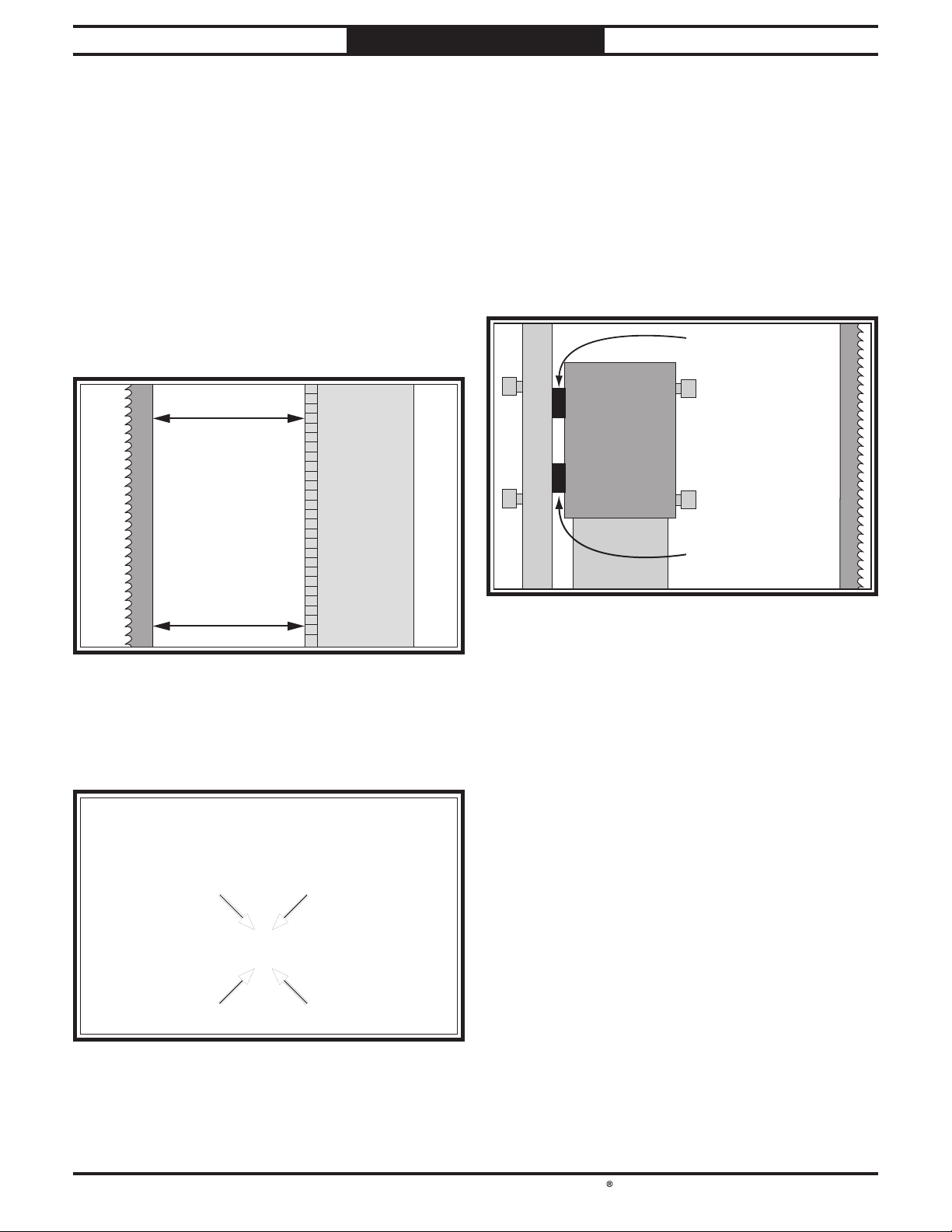
South Bend Tools
Model SB1123
SERVICE
For Machines Mfd. Since 7/21
4. Measure distance "A" between upper front
face of guide post rack and back of blade (see
Figure 99).
Measure distance "B" between bottom front
5.
face of guide post rack and back of blade (see
Figure 99).
— If measurements taken in Steps 4–5 are
equal, no adjustments need to be made.
Proceed to Step 9.
— If measurements taken in Steps 4–5 are
not equal, proceed to Step 6.
Distance "A"
Blade
(Right Side View)
— If distance between guide post and blade is
greater at bottom than at top, place a shim
between bottom of bracket and frame (see
Figure 101). This will tilt bottom of guide
post toward the blade.
— If distance between guide post and blade
is less at bottom than at top, place a shim
between top of bracket and frame (see
Figure 101). This will tilt bottom of guide
post away from blade.
Shim "B"
Frame
Guide
Bracket
(Left Side View)
Blade
Guide Post
Distance "B"
Figure 99. Example of measuring distance between Example of measuring distance between
guide post rack and blade.guide post rack and blade.
6. Loosen four cap screws shown in
Figure 100 just enough to fit metal shims
between frame and guide post bracket.
Shim "A"
Guide Post
Figure 101. Location for placing shims.. Location for placing shims.
Tighten four screws shown in Figure 100,
7.
then repeat Steps 4–5.
— If measurements are equal, proceed to
Step 9.
— If measurements are not equal, repeat
Steps 6–7 until guide post is parallel with
blade.
Install guide post guard using screws
8.
removed in Step 3.
Rotate upper wheel by hand and make sure
9.
blade does not contact guide post guard. If
it does, loosen screws from Step 3, adjust
guard so that blade will not make contact
with it, then tighten screws.
Figure 100. Guide post parallelism adjustment Guide post parallelism adjustment
screws.screws.
-62-

South Bend Tools
For Machines Mfd. Since 7/21 Model SB1123
SERVICE
Aligning Wheels
The following adjustment was performed at the
factory and should not need to be performed
again unless there is a wheel alignment problem,
or one or more wheels are replaced.
When wheels are coplanar (see F igure 102), the
bandsaw is more likely to cut straight without
wandering; and vibration, heat, and blade wear
are considerably decreased because the blade is
automatically balanced on the wheel.
or
Bringing the wheel into alignment may require a
combination of shimming a wheel and adjusting
the position of the lower wheel shaft.
Items Needed Qty
701⁄4" Long 2x4 ........................................... 1
Hex Wrenches 6, 8mm
Open-End Wrench or Socket 13mm
Tape Measure
Fine Ruler
............................................. 1
................................................. 1
..............................1 Ea
................. 1
Checking Wheel Alignment
1. Make "Coplanarity Gauge" shown in
Figure 103.
Note: For best results, straighten the 2x4
with a jointer before cutting. Alternatively,
you can cut the gauge out of a new sheet
1
⁄2"–3⁄4" plywood using a table saw. The
of
"factory edge" of the plywood will ensure a
straight and parallel gauge.
Coplanarity Gauge
Wheel Wheel
Wheels parallel and
coplanar.
Wheels parallel, but
not coplanar.
70
4"
21"
1
⁄4"
1
1
⁄2"
28
1
⁄4"
Upper wheel is not
vertically aligned with
lower wheel.
Figure 102. Wheel alignment illustration. Wheel alignment illustration.
Lower wheel is not
laterally aligned with
upper wheel.
21"
Side View
Figure 103. Dimensions of coplanarity gauge. Dimensions of coplanarity gauge.
-63-

South Bend Tools
Model SB1123
!
SERVICE
For Machines Mfd. Since 7/21
2. DISCONNECT MACHINE FROM POWER!
3. Remove blade (refer to Changing Blade on
Page 43), remove table, then re-install and
properly tension blade (refer to Tensioning
Blade beginning on Page 27).
Place coplanarity gauge up against both
4.
wheels in positions shown in Figure 104.
Make sure gauge fully extends across rims of
both wheels.
Coplanarity
Gauge
Tracking
Knob
Wheels
Adjustment
Hub
Gauge Positions
Check wheel alignment and adjust tracking
5.
knob to bring both wheels into alignment
as much as possible. If wheels cannot
be adjusted coplanar, use Figure 105 to
determine how to proceed with alignment
adjustments.
or
Coplanarity Gauge
Wheel Wheel
Wheels parallel and
aligned: No adjustment
needed.
Wheels parallel, but
not coplanar with each
other: Shim upper or
lower wheel out.
Figure 104. Illustration of using coplanarity gauge to Illustration of using coplanarity gauge to
check wheel alignment.check wheel alignment.
Upper wheel not
vertically aligned with
lower wheel: Use blade
tracking knob to tilt
upper wheel.
Figure 105. Wheel alignment illustration with Wheel alignment illustration with
solutions to misalignment problems.solutions to misalignment problems.
Lower wheel not
laterally aligned with
upper wheel: Adjust
rear adjustment set
bolts to tilt lower wheel
left/right.
-64-

South Bend Tools
For Machines Mfd. Since 7/21 Model SB1123
!
SERVICE
Shimming a Wheel
When the wheels are parallel but not coplanar,
one of the wheels must be shimmed out to bring
it into the same plane as the other wheel.
Tip: Standard washers work well for shimming
a wheel because they can easily be stacked to get
the desired height.
To shim a wheel:
1. DISCONNECT MACHINE FROM POWER!
Adjust upper wheel tracking so that it is
2.
parallel with lower wheel.
With coplanarity gauge touching both rims
3.
of wheel that does not need to be shimmed
out, measure distance away from other
wheel with a fine ruler (see Figure 106). The
distance measured with ruler is distance this
wheel must be shimmed.
8. Perform previous Checking Wheel
Alignment procedure, beginning on Page 63,
and adjust wheels as necessary make them
parallel and coplanar.
Tip: The first time you get the wheels
coplanar, place a mark on each wheel where
you held the coplanarity gauge, then use this
position again in the future if you need to
repeat the procedure. This assures repeated
accuracy every time you adjust the wheels.
— If no further adjustments are necessary,
remove blade, re-install table, and then
re-install blade.
— If the lower wheel is tilted in relation to
the upper wheel, proceed to Adjusting
Lower Wheel Shaft Position.
Adjusting Lower Wheel Shaft
Position
If the lower wheel is tilted in relation to the
upper wheel, perform the following procedure to
make it coplanar with the upper wheel.
Figure 106. Generic example photo of measuring the Generic example photo of measuring the
distance to shim a wheel to make it coplanar with distance to shim a wheel to make it coplanar with
other wheel.other wheel.
Remove blade.
4.
Remove wheel to be shimmed. Place as many
5.
shims as necessary to correct gap measured
in Step 3 onto wheel shaft.
Re-install and secure wheel.
6.
7. Re-install blade (refer to Changing Blade
on Page 43) and properly tension and track
blade.
There are four adjustment bolts with hex nuts in
the lower wheel adjustment hub, shown in Figure
107. These adjust the wheel tilt from side to side
and up and down.
Note: If you make a mistake during the following
procedure, it can be very difficult to correct.
Therefore, it is important to double check wheel
alignment (see Page 63), and troubleshoot all
other possible solutions (see Troubleshooting)
prior to adjusting the lower wheel shaft position.
Lower WheelLower Wheel
Adjustment HubAdjustment Hub
Figure 107. Location of rear adjustment components. Location of rear adjustment components.
-65-

South Bend Tools
Model SB1123
!
SERVICE
For Machines Mfd. Since 7/21
To adjust lower wheel shaft position:
1. DISCONNECT MACHINE FROM POWER!
Loosen jam nuts on lower wheel adjustment
2.
hub (see Figure 108).
Adjustment Adjustment
HubHub
Side Side
TiltTilt
Figure 108. Lower wheel adjustment controls. Lower wheel adjustment controls.
Loosen one tilt adjustment set screw, then
3.
tighten opposing set screw approximately an
equal amount.
Top TiltTop Tilt
Side Side
TiltTilt
Bottom TiltBottom Tilt
Calibrating Table Tilt Scale Pointer
The table tilt scale pointer (see Figure 109)
was calibrated at the factory. However, after
prolonged use the pointer may shift, requiring
adjustment.
Note: The table tilt scale functions as a basic
guide only. For high-precision cuts, use a
protractor or bevel gauge to set the angle of table
tilt.
PointerPointer
Table TiltTable Tilt
ScaleScale
Check wheels with coplanarity gauge, and
4.
repeat Step 3 as needed until lower wheel is
parallel and coplanar with upper wheel.
Tighten jam nuts to lock tilt adjustment set
5.
screws in position.
Perform previous Checking Wheel
6.
Alignment procedure, beginning on Page 63,
and adjust wheels as necessary to make them
parallel and coplanar.
When wheels are parallel and coplanar,
7.
remove blade, re-install table, and then reinstall blade.
Figure 109. Location of table tilt scale and pointer. Location of table tilt scale and pointer.
Tools Needed Qty
Machinist's Square ...................................... 1
Phillips Head Screwdriver #2
........................ 1
To calibrate table tilt scale pointer:
1. DISCONNECT MACHINE FROM POWER!
2. Place one edge of square on table and other
edge of square against blade side, as shown in
Figure 110.
Blade
-66-
Square
Table
Figure 110. Adjusting table perpendicular to blade Adjusting table perpendicular to blade
(side to side).(side to side).

South Bend Tools
For Machines Mfd. Since 7/21 Model SB1123
!
SERVICE
3. Adjust table tilt (refer to Tilting Table,
beginning on Page 45 for more information)
until square rests flush and evenly against
both table and blade side.
Note: Make sure square does not go across a
blade tooth when performing this step.
Loosen Phillips head screw that secures table
4.
tilt pointer (see Figure 109 on Page 66),
adjust pointer to "0" on scale, then retighten
screw.
Replacing Brake Shoe
The brake shoe needs to be replaced if one or more
of the following conditions are met:
• If the bandsaw takes noticeably longer to stop
when the foot brake is pushed.
• The foot brake makes metal-to-metal
grinding sounds.
• The thickness of the brake shoe pad measures
1mm or less.
4. Remove cap screws, lock washers, and
bushings that secure brake shoe to
brake lever, then remove brake shoe (see
Figure 111).
Brake ShoeBrake Shoe
Cap ScrewsCap Screws
Figure 111. Lower wheel removed to expose brake Lower wheel removed to expose brake
shoe components.shoe components.
5.
Install new brake shoe using cap screws, lock
washers, and bushings removed in Step 3.
Re-install V-belts and lower wheel.
6.
Brake LeverBrake Lever
Components and Hardware Needed
Replacement Brake Shoe (Part PSB1123026)
Tool(s) Needed Qty
Hex Wrenches 6, 8mm .............................. 1 Ea
... 1
To replace brake shoe:
1. DISCONNECT MACHINE FROM POWER!
2. Remove blade (refer to Changing Blade on
Page 43).
Remove lower wheel and V-belts (refer to
3.
Steps 1–6 in Replacing V-Belts on Page 58).
7. Tension V-belts (refer to Tensioning/
Replacing V-belts on Page 57).
Re-install, tension, and track blade,
8.
then adjust upper and lower blade guides
and support bearings as needed (refer to
Changing Blade on Page 43).
Close wheel covers.
9.
-67-

South Bend Tools
Model SB1123
TROUBLESHOOTING
TROUBLESHOOTING
For Machines Mfd. Since 7/21
If you need replacement parts, or if you are unsure how to do any of the solutions given here, feel free
to call us at (360) 734-1540.
Motor & Electrical
Symptom Possible Cause Possible Solution
Machine does not
start or a breaker
trips immediately
upon startup.
Main motor
stalls or is
underpowered.
1.
Keyed power switch in OFF
position.
2.
OFF button depressed/at fault.
3.
Door safety switch disengaged/at
fault.
4.
Incorrect power supply voltage or
circuit size.
5.
Plug/receptacle at fault/wired
incorrectly.
6.
Power supply circuit breaker
tripped or fuse blown.
7.
Motor wires connected incorrectly.
8.
Thermal overload relay has tripped/
at fault.
9.
Contactor not energized/at fault.
10.
Wiring broken, disconnected, or
corroded.
11.
ON button at fault.
12.
Motor or motor bearings at fault.
1.
Dull blade.
2.
Workpiece material unsuitable for
machine.
3.
Feed rate/cutting speed too fast.
4.
Workpiece crooked; fence loose or
misadjusted.
5.
Dust collection ducting problem.
6.
Machine undersized for task.
7.
Blade slipping on wheels or not
properly tensioned.
8.
Belt(s) slipping/pulleys misaligned.
9.
Motor wired incorrectly.
10.
Plug/receptacle at fault.
11.
Pulley slipping on shaft.
12.
Extension cord too long.
13.
Contactor not energized/at fault.
14.
Motor or motor bearings at fault.
1.
Turn keyed power switch to ON position.
2.
Rotate button head to reset. Replace if at fault.
3.
Close door. Adjust/replace limit switch (Page 72).
4.
Ensure correct power supply voltage and circuit
size.
5.
Test for good contacts; correct the wiring (Page 72).
6.
Ensure circuit is sized correctly and free of shorts.
Reset circuit breaker or replace fuse.
7.
Correct motor wiring connections (Page 72).
8.
Reset. Adjust/replace if at fault.
9.
Test all legs for power; replace if necessary.
10.
Fix broken wires or disconnected/corroded
connections.
11.
Replace button.
12.
Replace motor.
1.
Sharpen/replace blade (Page 43).
2.
Only cut wood/ensure moisture is below 20%.
3.
Decrease feed rate/cutting speed.
4.
Straighten or replace workpiece/adjust fence.
5.
Clear blockages, seal leaks, use smooth wall duct,
eliminate bends, close other branches.
6.
Use correct blade/reduce feed rate or depth of cut.
7.
Adjust blade tracking and tension (Page 28).
8.
Clean/tension/replace belt(s) (Page 57); ensure
pulleys are aligned (Page 63).
9.
Wire motor correctly (Page 72).
10.
Test for good contacts/correct wiring.
11.
Tighten/replace loose pulley/shaft.
12.
Move machine closer to power supply; use shorter
extension cord.
13.
Test all legs for power; repair/replace if at fault.
14.
Replace motor.
-68-

South Bend Tools
For Machines Mfd. Since 7/21 Model SB1123
TROUBLESHOOTING
Motor & Electrical (Cont.)
Symptom Possible Cause Possible Solution
Machine has
vibration or noisy
operation.
1.
Motor or component loose.
2.
Blade weld at fault/teeth broken.
3.
Blade at fault.
4.
V-belt(s) worn, loose, pulleys
misaligned or belt slapping cover.
5.
Pulley loose.
6.
Motor mount loose/broken.
7.
Motor fan rubbing on fan cover.
8.
Motor bearings at fault.
1.
Replace damaged or missing bolts/nuts or tighten
if loose.
2.
Replace blade (Page 43).
3.
Replace warped/bent blade; resharpen dull blade.
4.
Inspect/replace belts with a new matched set.
Realign pulleys if necessary (Page 63).
5.
Secure pulley on shaft.
6.
Tighten/replace.
7.
Fix/replace fan cover; replace loose/damaged fan.
8.
Test by rotating shaft; rotational grinding/loose
shaft requires bearing replacement.
Operating Machine
Symptom Possible Cause Possible Solution
Blade or teeth
break/crack.
1.
Blade tension is incorrect.
2.
Blade is incorrect for application.
3.
Excessive feed rate/pressure.
4.
Cutting corners too sharply.
5.
Blade is dull/weld at fault.
6.
Blade is tracking incorrectly.
7.
Blade guides/support bearings not
adjusted properly, allowing guides
to hit blade teeth.
8.
Wheel worn or incorrectly installed.
9.
Fence or miter slot out of alignment
with blade.
10.
Blade guide bearings at fault.
1.
Adjust blade tension (Page 27).
2.
Use correct blade for application (Page 38).
3.
Reduce feed rate/pressure.
4.
Use a wider arc on outside cuts, or use relief cuts to
make tight inside cuts.
5.
Replace blade (Page 43).
6.
Adjust blade tracking (Page 28).
7.
Adjust blade guides/support bearings properly, so
guides cannot contact teeth during operation (Page
29).
8.
Replace or re-install wheel.
9.
Align miter slot and fence with blade (Page 35).
10.
Replace blade guide bearings.
1.
Blade slows,
smokes, shows
overheating or
wear on one side.
Blade contacting table insert.
2.
Blade guides are worn or
misadjusted.
3.
Blade installed backwards.
4.
Too much side pressure when
feeding workpiece.
5.
Wheels are out of alignment.
6.
Dull, bell-mouthed, or incorrect
blade.
7.
Fence not parallel with blade.
8.
Table top surface is not parallel or
square to blade.
9.
V-belt loose or slipping.
1.
Adjust blade guides to eliminate any side pressure
(Page 30); properly align table (Page 32).
2.
Adjust upper blade guides as close to workpiece as
possible.
3.
Check blade rotation. Re-install blade if necessary
(Page 43).
4.
Feed workpiece straight into blade.
5.
Adjust wheels to be coplanar (Page 63).
6.
Replace blade (Page 43).
7.
Adjust fence parallel with blade (Page 33).
8.
Adjust/shim table/trunnion position until blade
and table are parallel and square (Page 32).
9.
Tighten V-belt. Replace if worn or oily. (Page 57).
-69-

South Bend Tools
Model SB1123
TROUBLESHOOTING
For Machines Mfd. Since 7/21
Operating Machine (Cont.)
Symptom Possible Cause Possible Solution
Finished
workpieces are
rough or show
scoring.
Table is hard to
tilt.
Table does not tilt
to 45 or 0 degrees.
Blade tracks
incorrectly or
comes off wheels.
1.
Blade is overloaded and twists.
2.
Blade TPI is too coarse.
3.
Blade is loose and fluttering.
4.
Blade tracking is incorrect.
5.
Blade has missing/bent teeth, or
faulty weld.
1.
Table tilt lock lever is engaged.
2.
Sawdust or pitch trapped between
trunnion and base.
3.
Metal burrs on trunnion.
1.
Table tilt scale pointer not
calibrated.
2.
Positive stop not set correctly.
1.
Tracking is not adjusted properly.
2.
Wheels are not coplanar.
3.
Blade tension too loose.
4.
Blade guides/support bearings
improperly adjusted.
5.
Feeding workpiece too fast.
6.
Incorrect blade for operation.
7.
Blade is bell-mouthed, worn, or
dull.
8.
Wheel is damaged or worn.
1.
Decrease feed rate; ensure proper TPI (Page 38).
2.
Use correct blade for material and speed of cut
(Page 38).
3.
Adjust blade tension as required (Page 27).
4.
Adjust blade tracking (Page 28).
5.
Replace blade (Page 43).
1.
Disengage table tilt lock lever (Page 44).
2.
Remove table and clean trunnion sliding surfaces
free of sawdust or pitch.
3.
Remove burrs.
1.
Calibrate table tilt scale pointer (Page 66).
2.
Adjust positive stop (Page 44).
1.
Adjust tracking (Page 28).
2.
Adjust wheels to be coplanar (Page 63).
3.
Increase blade tension (Page 27).
4.
Properly adjust blade guides/support bearings
(Page 28).
5.
Feed workpiece slower.
6.
Install correct blade (Page 38).
7.
Install new blade and remove tension from blade
when not in use.
8.
Replace wheel.
Cut is crooked
or blade wanders
(blade lead).
1.
Excessive feed rate/pressure.
2.
Blade tension too loose.
3.
Blade is too narrow or tooth type/
TPI is incorrect for the cut.
4.
Inadequate blade support.
5.
Blade dull or has damaged tooth
set from improper guides/support
bearing adjustment.
6.
Blade tracking is incorrect.
7.
Table is loose.
8.
Fence or miter slot out of alignment
with blade.
9.
Blade guides/support bearings
improperly adjusted.
10.
Tooth set is uneven or teeth are
sharper on one side than the other.
1.
Reduce feed rate/pressure.
2.
Increase blade tension (Page 27).
3.
Use wider blade. Ensure tooth type and TPI are
correct (Page 38).
4.
Position upper blade guides to just clear workpiece.
Properly adjust blade guides/support bearings
(Page 28).
5.
Replace blade (Page 43).
6.
Adjust blade tracking (Page 28).
7.
Tighten table trunnion mounting bolts or tilt lock
lever (Page 44).
8.
Align miter slot and fence with blade (Page 35).
9.
Properly adjust blade guides/support bearings
(Page 32).
10.
Replace blade (Page 43).
-70 -

South Bend Tools
For Machines Mfd. Since 7/21 Model SB1123
TROUBLESHOOTING
Operating Machine (Cont.)
Symptom Possible Cause Possible Solution
Blade dulls
prematurely.
Gullets loaded with
chips.
Back side of blade
deformed/cracked.
Sawdust buildup
inside cabinet.
1.
Excessive feed rate/pressure.
2.
Wrong blade tooth type or TPI.
3.
Blade is twisted.
4.
Blade is slipping on wheel.
5.
Blade guides hitting teeth and
ruining tooth set.
1.
Excessive feed rate/pressure.
2.
Blade TPI is too fine.
1.
Excessive feed rate/pressure.
2.
Blade tension too high.
3.
Blade support bearings improperly
adjusted.
1.
Blade brushes under table are worn
or misadjusted.
2.
Clogged dust port.
3.
Low CFM (airflow) from dust
collection system.
1.
Reduce feed rate/pressure.
2.
Use blade with correct tooth type and TPI (Page 38).
3.
Re-install blade; replace (Page 43).
4.
Adjust blade tension (Page 27).
5.
Properly adjust guide bearings (Page 30).
1.
Reduce feed rate/pressure.
2.
Install correct blade (Page 38).
1.
Reduce feed rate/pressure.
2.
Adjust blade tension (Page 27).
3.
Properly adjust blade support bearings (Page 28).
1.
Properly adjust brushes; replace if necessary (Page
59).
2.
Clean dust port.
3.
Inspect ducting for leaks/clogs and repair as
necessary; move dust collector closer to machine;
install a stronger dust collector (Page 21).
-71-

South Bend Tools
Model SB1123
Shock Hazard: It is extremely dangerous to
Wire Connections:
Modifications:
Motor Wiring:
junction box.
Circuit Requirements: Connecting the machine
power inverters store an electrical charge for
our Technical Support at (360) 734-1540.
ELECTRICAL
For Machines Mfd. Since 7/21
Electrical Safety Instructions
These pages are accurate at the time of printing. In the constant effort to improve, however, we may
make changes to the electrical systems of future machines. Study this section carefully. If you see
differences between your machine and what is shown in this section, call Technical Support at (360)
734-1540 for assistance BEFORE making any changes to the wiring on your machine.
perform electrical or wiring tasks while the
machine is connected to the power source.
Touching electrified parts will result in
personal injury including but not limited to
severe burns, electrocution, or death. For
your own safety, disconnect machine from
the power source before servicing electrical
components or performing any wiring tasks!
All connections must be
tight to prevent wires from loosening during
machine operation. Double-check all wires
disconnected or connected during any wiring
task to ensure tight connections.
Using aftermarket parts or
modifying the wiring beyond what is shown
in the diagram may lead to unpredictable
results, including serious injury or fire.
The motor wiring shown in these
diagrams is current at the time of printing,
but it may not match your machine. Always
use the wiring diagram inside the motor
to an improperly sized circuit will greatly
increase the risk of fire. To minimize
this risk, only connect the machine to a
power circuit that meets the minimum
requirements given in this manual.
Capacitors/Inverters: Some capacitors and
up to 10 minutes after being disconnected
from the power source. To reduce the risk of
being shocked, wait at least this long before
working on capacitors.
Wire/Component Damage: Damaged wires
or components increase the risk of serious
personal injury, fire, or machine damage. If
you notice that any wires or components are
damaged while performing a wiring task,
replace those wires or components before
completing the task.
Experiencing Difficulties: If you are
experiencing difficulties understanding the
information included in this section, contact
BLACK
BLUE
BROWN
NOTICE:
-72-
WIRING DIAGRAM COLOR KEY
BLUE
WHITE
GREEN
G R AY
The photos and diagrams included in this section are best viewed in color. You can
see them in color at www.southbendtools.com.
RED
LIGHT
BLUE
ORANGE
PINK
PURPLE
TURQUIOSE
WHITE
YEL LOW
GREEN
YEL LOW

South Bend Tools
For Machines Mfd. Since 7/21 Model SB1123
ELECTRICAL
220V Wiring
Wiring Diagram 220V
!
WARNING!
!
220V Mag Switch
SDE M PE-18
SHOCK HAZARD!
Disconnect power
before working on
wiring.
Control Panel
22 21
KEY SWITCH
2
YK 22-1A1BG
14 13
2
2
6
Upper
Wheel Cover
11 12
23 24
T
A
L1/1 L3/5 NO13L2/3
T1/2 T3/6
1/2 3/4 5/6
W
W
V
E
U
MA-18
T2/4
U V
SDE
22
ON BUTTON
YK 22-1A1B
2
SR
NC21
SDE
NC22
NO14
SDE RA-30
18-26A
26
96
RESET
AMP
18
22
98
95
E
Ground
E
T
S
R E
14 13
OFF BUTTON
TAICHUAN
TPB22-S01R
21
NCNC
12
Foot
Brake
2
6
NO
NC
LIMIT SWITCH
CANLI E KL7141
LIMIT
SWITCH
CANLIE
AZDS11
C
U2
GND
U5
Motor 220V
U1
V1
V2
V5
W1
W2
W5
= For phase
converter wild
wire (if used)
T
S
Power Supply
Junction Box
220 VAC 3-Phase
E
R
E
Ground
DISCONNECT SWITCH
(as recommended)
Hot
Hot
-73-

South Bend Tools
Model SB1123
ELECTRICAL
Wiring Diagram 440V
!
WARNING!
!
440V Mag Switch
SDE M PE-18
SHOCK HAZARD!
Disconnect power
before working on
wiring.
2
For Machines Mfd. Since 7/21
Control Panel
22 21
KEY SWITCH
2
YK 22-1A1BG
14 13
2
440V Wiring
Upper
Wheel Cover
11 12
6
23 24
T
A
L1/1 L3/5 NO13L2/3
T1/2 T3/6
1/2 3/4 5/6
W
W
UVE
MA-18
T2/4
U V
SDE
22
ON BUTTON
YK 22-1A1B
2
SR
NC21
SDE
NC22
NO14
SDE RA-20
8-12A
RESET
AMP
8
12
10
98
96
95
E
Ground
E
T
S
R E
14 13
OFF BUTTON
TAICHUAN
TPB22-S01R
21
NCNC
12
Foot
Brake
2
6
NO
NC
LIMIT SWITCH
CANLI E KL7141
LIMIT
SWITCH
CANLIE
AZDS11
C
U2 U5
GND
Motor 440V
U1
-74-
V2
V1
V5
W2
W1
W5
= For phase
converter wild
wire (if used)
T
S
Power Supply
Junction Box
440V Conversion
3-Phase 440 VAC
E
R
E
Ground
DISCONNECT SWITCH
(as recommended)
Hot
Hot

South Bend Tools
For Machines Mfd. Since 7/21 Model SB1123
ELECTRICAL
Electrical Component Pictures
Figure Figure 114. Control panel wiring.. Control panel wiring.Figure Figure 112. Magnetic switch wiring (220V).. Magnetic switch wiring (220V).
Figure Figure 115. Foot brake limit switch. . Foot brake limit switch. Figure Figure 113. Upper wheel cover limit switch.. Upper wheel cover limit switch.
-75-

South Bend Tools
Model SB1123
Figure Figure 116. 220V motor junction box wiring (220V).. 220V motor junction box wiring (220V). Figure Figure 117. Power supply junction box (220V).. Power supply junction box (220V).
ELECTRICAL
For Machines Mfd. Since 7/21
-76-

South Bend Tools
For Machines Mfd. Since 7/21 Model SB1123
PARTS
PARTS
Main
238
211
217
217
212
205
206
207
208
205
206
207
227
33
41
40
201
227
218
218
33
33
42
34
38
39
201-2
36
37
201-1
201-4
202-2
202-5
2-2
2-7
2-3
2-5
2-7
2-10
35
202-1
2-1
2-4
2-6
2-9
226
201-5
2-12
137
2-8
2-13
11
33
43
2
1
4
3
201-3
201-2
202-6
101
108
107
105
202-7
202-2
2-19
2-17
2-18
2-11
2-15
2-16
2-14
105
209
202-3
2-12
2-13
139
10
5
127
50
17
107 108
202-4
202
125
130
124
239
14
106
110-13
110-12
110-11
110-10
110-9
110-2
110-4
110-3
6
12
119
19
20
220
221
26
104
108
180
190
200
28
31
110-27
101
116
45
25
30
46
120
103
108
110
115
113
117-9
110-6
110-20
111
102
114
112
116-8
117
117-7
117-8
117-10
31
7
8
9
13
16
15
123
122
21
11
118
108
128
129
121
120
180
190
200
18
219
44
109
108
104
46
24
29
22
32
3
240 241
110-5
116-10
117-1
117-6
30
31
27
32
242
110-7
116-11
116-9
117-14
23
110-14
110-8
116-12
117-5
51
110-1
110-22
116-7
117-4
117-12
117-11
110-15
110-18
110-26
110-24
110-21
110-23
116-3
116-6
117-13
47
110-25
110-19
116-1
116-2
116-4
116-2
116-5
117-2
117-3
117-1
48
49
-77-

South Bend Tools
Model SB1123
PARTS
For Machines Mfd. Since 7/21
Main Parts List
REF PART # DE SCR IPTION REF PAR T # DE SCR IPT ION
1 PSB1123001 M A CH IN E B ODY 33 PSB1 1 230 33 TAP S CREW M 4 X 10
2 PSB1123002 UPPER WHEEL SLIDING ASSEMBLY 34 PS B11 230 34 COMPRESSION SPRING 1 X 8 X 40
2-1 PSB 1123002-1 SET SCREW M10-1.5 X 16 35 PS B11 230 35 UPPER WHEEL SLIDING BRACKET
2-2 PSB1123002-2 GUIDE B LOC K 36 PS B 112 3036 MOVING PLATE
2-3 PSB1123002-3 UPPER WHEEL SH AFT 37 PSB1 1 230 37 ROLL PIN 3 X 1 2
2-4 PSB1123002-4 COMPRESSION SPRING 12 X 4 X 70 38 PSB 1 12 3038 FIXED PLATE
2-5 PSB1123002-5 BUSHING 39 P SB1 1 230 39 TENSION POINTER
2-6 PSB1123002-6 PRESS BLOCK 40 PSB1123040 TENSION SCALE
2-7 PSB1123002-7 SET S CREW M5-.8 X 5 41 PSB1123041 FLAT WASHER 4MM
2-8 PSB 1123002-8 LOCK WASH ER 8MM 42 PSB1123042 TEN S ION WIRE
2-9 PSB1123002-9 THRUST B EA RIN G 51201 43 PSB1123043 CORD CLAMP 3/16"
2-10 PSB1123002-10 HANDWHEEL SHAFT 44 PSB1123044 GUA RD STRIP
2-11 PSB1123002-11 SQUARE SHAFT 45 PSB1123045 F ENDER WASH ER 13 X 26 X 0 .7 COPPER
2-12 PSB1123002-12 FLAT WASHER 8MM 46 PSB1123046 SET SC REW M7-1 X 10
2-13 PSB1123002-13 CAP SCREW M8-1.25 X 20 47 PSB1123047 RISER BLOCK
2-14 PSB1123002-14 UPPER WHEEL HINGE ASSEMB LY 48 PSB1123048 HEX BOLT M12-1.75 X 100
2-15 PSB1123002-15 FLAT HD CAP SCR M5-.8 X 16 49 PSB1123049 LOCK WASHER 12M M
2-16 PSB1123002-16 LOCATE P LATE 50 PSB1123050 HEX NUT M10-1.5
2-17 PSB1123002-17 HEX NUT M 8-1.2 5 51 PSB1123051 FLAT WASHER 12MM
2-18 PSB1123002-18 BUSHING 101 PSB1123101 CAP SCREW M6-1 X 25
2-19 PSB1123002-19 H EX BOLT M8-1.25 X 90 102 PSB1123102 LOCK WASH ER 8MM
3 PSB1123003 CAP SCREW M6-1 X 25 103 PSB1123103 LOCK WASHER 6MM
4 PSB1123004 HANDWHEEL TYPE-35 178D X 14B-S 104 PSB1123104 CAP SCREW M6-1 X 10
5 PSB1123005 HOUSING PLATE 105 PSB1123105 HEX NUT M6-1 NYLON
6 PSB1123006 ECCENTRIC SHAFT 106 PSB1123106 HEX BOLT M6-1 X 25
7 PSB1123007 HEX N UT M1 6-2 107 PSB1123107 BRUS H
8 PSB1123008 HANDLE SHAFT 470MM M16-2 108 PSB1123108 FLAT WASHER 6MM
9 PSB1123009 HANDLE SLEEVE 109 PSB1123109 S UPPORT PLATE
10 PSB1123010 CAM 110 PSB1123110 UPPER BLADE GUIDE POST ASSEM BLY
11 PSB1123011 CAP SCREW M8-1.25 X 25 110-1 PSB1123110-1 UPPER B LADE GUIDE SUPPORT BLOCK
12 PSB1123012 KN OB B OLT M 1 0- 1. 5 X 55, 6- LOB E, D62 110-2 PSB1123110-2 HEX NUT M5-. 8
13 PSB1123013 LOCK HA NDLE M10 -1.5 110-3 PSB1123110-3 PHLP HD SCR M5-.8 X 10
14 PSB1123014 FLAT WASHER 10MM 110-4 PSB1123110-4 C OVER
15 PSB1123015 LOCK WASHER 10MM 110-5 PSB1123110-5 LOCK WASH ER 8MM
16 PSB1123016 PHLP HD SCR M10-1.5 X 25 110-6 PSB1123110-6 CAP SCREW M8-1.25 X 16
17 PSB1123017 LOWER WHEEL SHA FT 110-7 PSB1123110-7 F LAT HD SCR M4-.7 X 10
18 PSB1123018 C OVER 110-8 PSB1123110-8 EXTEN SION RA CK
19 PSB1123019 PHLP HD SCR M8-1.25 X 20 110-9 PSB1123110-9 COVE R
20 PSB1123020 SET S CREW M 10 -1.5 X 30 110-10 PSB1123110-10 PI N ION GE AR BOLT
21 PSB 1123021 HEX NUT M10-1.5 110-11 PSB1123110-11 PINION GEAR
22 PSB1123022 LOCK WAS HER 8M M 110-12 PSB1123110-12 FIXED PLATE
23 PSB 1123023 B RAKE LEVER 110-13 PSB1123110-13 WORM SHAFT
24 PSB1123024 BUSHING 110-14 PSB1123110-14 HEX NUT M16-1.5
25 PSB1123025 BUSHING 110-15 PSB1123110-15 GUIDE BRACKET
26 PSB1123026 B RAKE SH OE 110-18 PSB1123110-18 BUSHING
27 PSB1123027 BRAKE PEDAL 110-19 PSB1123110-19 LOCK COLLAR
28 PSB1123028 EXTENSION SPRING 1.6 X 40 X 63 110-20 PSB1123110-20 RA CK
29 PSB1123029 FLAT WASHER 8MM 110-21 PSB1123110-21 CAP SCREW M6-1 X 16
30 PSB 1 1230 30 H EX N UT M6-1 110-22 PSB1123110-22 HEX N UT M4-. 7
31 PSB 1 123031 CAP SCREW M6-1 X 16 110-23 PSB1123110-23 PHLP HD SCR M4-.7 X 10
32 P SB 1 1230 32 LOCK WASHER 6MM 110-24 PSB1123110-24 SET S CREW M5-.8 X 5
-78 -

South Bend Tools
For Machines Mfd. Since 7/21 Model SB1123
PARTS
Main Parts List (Cont.)
REF PART # DE SCR IPTION REF PAR T # DE SCRIPTION
110-25 PSB1123110-25 FIB ER WASH ER 10MM 125 PSB1123125 H EIGHT P OINTER
110-26 PSB1123110-26 BUS H IN G DU 10 X 12 127 PSB1123127 HEX B OLT M10 -1.5 X 50
110-27 PSB1123110-27 FLAT WASHER 5MM 128 PSB1123128 PLEXIGLASS WIN DOW
111 PSB1123111 K NOB BOLT M10 -1 . 5 X 2 5, 6- LOB E, D62 129 PSB1123129 RIVET 3.2 X 1 0
112 PSB1123112 HANDWH EEL TYPE-35 178D X 14B-S X M10 -1.5 130 PSB1123130 FLAT WASHER 5MM
113 PSB1123113 FIXED HAN DLE 24 X 90, M10-1.5 X 12 137 PSB1123137 CAP SCREW M8-1.25 X 20
114 PSB1123114 FLAT WASHER 8MM 139 PSB1123139 EYE B OLT M12-1.75 X 22
115 PSB1123115 B UTTON HD CAP SCR M8-1.25 X 30 180 PSB1123180 HEX NUT M6-1 NYLON
116 PSB1123116 UPPER BLADE GUIDE ASSEM BLY 190 PSB1123190 KN OB 6M M, D6 0, 1 0-LOB E
116-1 PSB1123116-1 UPPER BLADE GUIDE SUPPORT BAS E 200 PSB 1123200 CAP SCREW M6-1 X 20
116-2 PSB1123116-2 H EX BOLT M6-1 X 16 201 PSB1123201 UPPER WHEEL AS SEMBLY
116-3 PSB1123116-3 ADJUSTING SHAFT 201-1 PSB1123201-1 UPPER WHEEL 24"
116-4 PSB1123116-4 B LA DE GUIDE S UP PORT 201-2 PSB1123201-2 BALL B EA RIN G 6306 -2RS
116-5 PSB1123116-5 BEARING SHAFT 201-3 PSB1123201-3 PHLP HD SCR M6-1 X 8
116-6 PSB1123116-6 B ALL B EA RIN G 620 1ZZ 201-4 PSB1123201-4 BUSHING
116-7 PSB1123116-7 EXT RETAIN ING RIN G 12M M 20 1-5 PSB1123201-5 PRESS PLA TE
116-8 PSB1123116-8 CAP SCREW M6-1 X 40 202 PSB1123202 LOWER WHEEL ASSSEMB LY
116-9 PSB1123116-9 BEARING BUSHING 202-1 PSB1123202-1 LOWER WHEEL 24"
116-10 PSB1123116-10 B ALL B EARING 620 2Z Z 202-2 PSB1123202-2 B ALL BEA RIN G 630 6-2RS
116-11 PSB1123116-11 EXT RETAINING RIN G 15MM 202-3 PSB1123202-3 PHLP HD SCR M6-1 X 8
116-12 PSB1123116-12 ECCENTRIC SH AFT 202-4 PSB1123202-4 BUTTON HD CAP SCR M8-1.25 X 20
117 PSB1123117 LOWER BLADE GUIDE AS SEMBLY 202-5 PSB1123202-5 BUSHING
117-1 PSB1123117-1 HEX BOLT M6-1 X 16 202-6 PSB1123202-6 PRES S P LATE
117-2 PSB1123117-2 CAP SCREW M6-1 X 16 202-7 PSB1123202-7 WHEEL PULLEY
117-3 PSB1123117-3 FLAT WASHER 6MM 205 PSB1123205 F ENDER WASH ER 9 X 40 X 3MM
117-4 PSB1123117-4 ADJUSTING SHAFT 206 PSB1123206 LOCK WASH ER 8MM
117-5 PSB1123117-5 BLA DE GUIDE SUPPORT 207 PSB1123207 CAP SCREW M8-1.25 X 20
117-6 PSB1123117-6 ECCENTRIC SHAFT 208 PSB1123208 SAW BLADE 181 X 1 X 0.35 HOOK
117-7 PSB1123117-7 EXT RETAINING RING 15MM 209 PSB1123209 V-BELT 17-340
117-8 PSB1123117-8 BALL BEA RIN G 6202ZZ 211 PSB1123211 UPPER WHEEL COVER
117-9 PSB1123117-9 CAP SCREW M6-1 X 40 212 PSB1123212 LOWER WHEEL COVER
117-10 PSB1123117-10 BEARING BUSHING 217 PSB1123217 CAP SCREW M6-1 X 10
117-11 PSB1123117-11 BALL B EARING 620 1Z Z 218 PSB1123218 H EX N UT M6-1
117-12 PSB1123117-12 BEARING SHAFT 219 PSB1123219 ADJUSTABLE PLATE
117-13 PSB1123117-13 S UPPORT BRACKET 220 PSB 1123220 CAP SCREW M5-.8 X 12
117-14 PSB1123117-14 EXT RETA IN IN G RIN G 12M M 221 PSB1123221 FLAT WASHER 5MM
118 PSB1123118 BLADE GUARD 226 PSB 1123226 H EX N UT M8-1 .25
119 PSB1123119 L-BRACKET 227 PSB1123227 PHLP HD SCR M4-.7 X 10
120 PSB1123120 CAP SCREW M6-1 X 12 238 PS B 112 3238 FLANGE NUT M4-.7
121 PSB1123121 SLIDIN G PLATE 239 P SB 1 123239 WRENCH 17 X 19MM OPEN-ENDS
122 PSB1123122 SHOULDER SCREW M4-.7 X 5, 6 x 3 240 PSB1123240 WRENCH 10 X 13MM OPEN-ENDS
123 PSB1123123 FLAT WASHER 6MM PLASTIC 241 PSB1123241 HEX WRENCH 6 MM
124 PSB1123124 PHLP HD SCR M5-.8 X 10 242 PSB1123242 HEX WRENCH 5MM
-79-

South Bend Tools
Model SB1123
PARTS
Table, Tilt, Trunnion & Fence
317-12
317-13
317-1
317-10
317-9
317-11
317-6
317-7
317-14
317-15
317
317-8
317-4
317-16
317-5
317-2
317-3
322-12
322-7
322-11
322-24
322-10
For Machines Mfd. Since 7/21
322-21
322-20
322-13
322-9
322-18
322-19
307
322-3
322-2
322-8
322-15
322-14
322
307
322-23
322-1
322-4
301
325
322-22
322-5
322-6
322-17
322-16
310
309
315
314
307
306
316
335
337
302
303
323
308
311
343
328
336
344
313
334
330
329
326
320
338
333
331
332
312
330-2
330-8
330-7
330-3
330-1
330-4
330-5
330-6
324
318-4
318-11
318-10
318-14
318-13
318-7
318-1
319
318-5
318-5
318
318-6
321
306
307
304
318-12
318-9
318-15
318-8
318-2
318-3
-80-

South Bend Tools
For Machines Mfd. Since 7/21 Model SB1123
PARTS
Table, Tilt, Trunnion & Fence Parts List
REF PART # DE SCR IPTION REF PART # DESCRIPT ION
301 PSB 1 12 3301 CAP SCREW M6-1 X 25 322 PS B 112 3322 TAB LE TILT AS SEMB LY
302 P SB1 1 2330 2 FLAT WASHER 10MM 322-1 PSB1123322-1 GUIDE BRACKET
303 PS B 112 3303 LOCK WASHER 10MM 322-2 PSB1123322-2 WORM SHAFT
304 PSB 1 12330 4 BUTTON HD CAP SCR M8-1.25 X 20 322-3 PSB1123322-3 HEX NUT M16-1.5
306 PSB 1 12330 6 LOCK WASHER 8MM 322-4 PSB1123322-4 BUSHING
307 PSB1 1 2330 7 FLAT WASHER 8MM 322-5 PSB1123322-5 LOCK COLLAR
308 P SB 1 12330 8 CAP SCREW M6-1 X 10 322-6 PSB1123322-6 SET SCREW M5-. 8 X 5
309 PS B 11 23309 HAN DWHEEL TYPE-35 178D X 14B-S X M10-1.5 322-7 PSB1123322-7 HEX NUT M 5-.8
310 PSB1123310 FIXED HANDLE 24 X 90, M10-1.5 X 12 322-8 PSB1123322-8 LOCK WAS HER 8M M
311 PSB1123311 CAP SCREW M10-1.5 X 35 322-9 PSB1123322-9 CAP SCREW M8-1.25 X 16
312 PSB1123312 TABLE 322-10 PSB1123322-10 PHLP HD SCR M5-.8 X 10
313 PSB1123313 TABLE INSERT 322-11 PSB1123322-11 H OUS IN G C OVER
314 PSB1123314 FEN CE RAIL M OUNTING PLA TE 322-12 PSB1123322-12 GEAR COVER
315 PSB1123315 FENCE RAIL 322-13 PSB1123322-13 PI N ION GE AR BOLT
316 PSB1123316 H EX BOLT M8-1.25 X 20 322-14 PSB1123322-14 EX TENSION RACK
317 PSB1123317 FEN CE AS SEMBLY 322-15 PSB1123322-15 F LAT H D SC R M4-. 7 X 10
317-1 PSB1123317-1 FENCE 322-16 PSB1123322-16 RACK
317-2 PSB1123317-2 POIN TER 322-17 PSB1123322-17 SQUA RE TUB E
317-3 PSB1123317-3 PHLP HD SCR M5-.8 X 8 322-18 PSB 1123322-18 PHLP HD SCR M4-.7 X 10
317-4 PSB1123317-4 PLATE SPRING 322-19 PSB1123322-19 HEX N UT M4-. 7
317-5 PSB1123317-5 PHLP HD SCR M4-.7 X 8 322-20 PSB1123322-20 PIN ION GEAR 15T
317-6 PSB1123317-6 LOCK CAM 322-21 PSB1123322-21 FIXED PLATE
317-7 PSB1123317-7 HEX ADAPTER M8-1.25 X 10, 1/4-20 X 9 322-22 PSB1123322-22 FIBER WAS HER 10 MM
317-8 PSB1123317-8 SHAFT 322-23 PSB1123322-23 B USHING DU 10 X 1 2
317-9 PSB1123317-9 S ET SCREW M7-1 X 1 0 322-24 PSB1123322-24 FLAT WASHER 5MM
317-10 PSB1123317-10 NYLON PAD 10 X 28 X 1 323 PS B 11 23323 FLAT WASHER 6MM
317-11 PSB1123317-11 SET SC REW M8 -1.25 X 12 324 P SB11 2332 4 HEX BOLT M8-1. 25 X 55
317-12 PSB1123317-12 CAP SCREW M8-1.25 X 20 325 P SB1 1 2332 5 HEX NUT M8-1 .25 NYLON
317-13 PSB1123317-13 H EX N UT M8-1 .25 326 PS B 11 23326 HEX NUT M 8-1.25
317-14 PSB1123317-14 KNOB M8-1.25, D30, TAPERED 328 PS B11 2332 8 CAP SCREW M8-1.25 X 50
317-15 PSB1123317-15 FLAT WASHER 5MM 32 9 PS B 11 23329 FLAT WASHER 8MM
317-16 PSB1123317-16 FLAT WASHER 4MM 330 PS B11 23330 TRUNNION BLOCK ASSEMBLY
318 PSB1123318 MITER GAUGE A SSEMBLY 330-1 P SB 1 123330 -1 TRUNNION HOUSING
318 -1 PSB1123318-1 MITER B AR 330-2 P SB11 23330 -2 TRUNNION BLOCK
318 -2 PSB1123318-2 GUI DE DI SC 330-3 PSB11 23330 -3 PRESSBLOCK
318 -3 PSB1123318-3 F LAT HD SC R M6 -1 X 8 330 -4 P SB 1 123330 -4 PRESS SHAFT
318 -4 PSB1123318-4 POINTER 330-5 P SB1 1 23330 -5 MICRO ADJUSTMEN T RIN G
318 -5 PSB1123318-5 PHLP HD SCR 3/16-24 X 3/8 330-6 PS B 11 23330-6 LOCK WASHER 8MM
318 -6 PSB1123318-6 SHOULDER SCREW M6-1 X 10, 8 X 4 330-7 PS B11 23330 -7 CAP SCREW M8-1.25 X 25
318 -7 PSB1123318-7 MITE R GA UGE B ODY 330-8 PS B 1123330-8 ROLL PIN 6 X 36
318 -8 PSB1123318-8 FLAT WASHER 8MM 331 PS B11 23331 HANDLE SHAFT M12-2 90MM
318 -9 PSB1123318-9 HEX ADAPTER 5/16-18 X 15, 1/4-20 X 9 332 PS B 1123332 SLEEVE
318-10 PSB1123318-10 INDEXING BLOCK 333 PS B 11 23333 HEX NUT M12-1.75
318-11 PSB1123318-11 INDEXING PIN 334 PS B 112 3334 POIN TER
318-12 PSB1123318-12 KN OB 5/16-18, D30, TAPERED 335 PS B 112 3335 BLADE GUARD
318-13 PSB1123318-13 H EX NUT M 4-.7 336 P SB1 1 23336 CAP SCREW M10-1.5 X 35
318-14 PSB1123318-14 PHLP HD SCR M4-.7 X 16 337 PS B 11 23337 PHLP HD SCR M6-1 X 10
318-15 PSB1123318-15 SC ALE 338 PSB1 1 23338 PHLP HD SCR M4-.7 X 10
319 PSB1123319 SUPPORT PLA TE 343 P SB 1 123343 FLAT WASHER 10MM
320 P SB1 1 2332 0 SLIDIN G PLA TE 344 PS B 112 3344 LOCK WASHER 10 MM
321 PS B 112 3321 CAP SCREW M8-1.25 X 30
-81-

South Bend Tools
Model SB1123
Motor & Electrical
PARTS
For Machines Mfd. Since 7/21
416
412
413
414
415
444
445
435
423
421
422
435
423
440
405
404
407
403
426
410
440
424
432-1
437
411
425
432 (220V)
432-2
432-3
436
438
406
409
432-4
446
407
408
408-1
408-4 408-5
408-3
453-1
408-2
453 (440V)
453-2
453-4
453-3
443
434
435
430
416
433
441
451
433
442
433
450
433
427
449
452
448
447
431
-82-

South Bend Tools
For Machines Mfd. Since 7/21 Model SB1123
PARTS
Motor & Electrical Parts List
REF PART # DE SCR IPTION REF PAR T # DE SCR IPTION
403 PSB1123403 CAP SCREW M8-1.25 X 25 432-1 P SB1 1 23432-1 BA CK COVER
404 PSB1123404 FLAT WASHER 10MM 432-2 PSB 1 123432 -2 C ONTA CTOR S DE MA -18 60 0 V
405 PSB1123405 HEX NUT M10-1.5 432-3 PSB 1 123432 -3 OL RELAY SDE RA-30 18-26A
406 PSB1123406 CAP SCREW M8-1.25 X 20 432-4 P SB 1 123432 -4 F RON T COVER
407 PSB1123407 FLAT WASHER 8MM 433 PSB1 1 23433 S TRAIN RELIEF TYPE-3 M20-1.5
408 PSB1123408 MOTOR 7.5HP 2 20V/ 44 0 V 3PH 434 P SB 1 123434 CORD CLAMP 5/8"
408 -1 PSB1123408-1 FAN COVER 435 PS B11 234 35 TAP SCREW M4 X 8
408 -2 PSB1123408-2 FAN 436 PSB 1 123436 LIMIT SWITCH CANLIE AZDS11
408 -3 PSB1123408-3 JUNCTI ON B OX 437 PS B 11 23437 PHLP HD SCR M4-.7 X 35
408 -4 PSB1123408-4 F RONT B EA RIN G 6206-2RS 438 PSB 1 123438 FLANGE NUT M4-.7
408 -5 PSB1123408-5 REA R BEARING 6204-2RS 440 PSB1123440 LIM IT SWITCH CORD 18 G 2W 60"
409 PSB1123409 PULLEY 441 PSB 11 23441 MAG SWITCH CORD 12G 4W 16"
410 PSB1123410 ADJ UST BOLT 442 PSB 1123442 POWER SUPPLY CORD 12G 4W 18-1/2"
411 PSB1123411 S ET S CREW M 6-1 X 1 2 443 PSB 1123443 MOTOR CORD 12 G 4W 30"
412 PSB1123412 S WITCH PLA TE 444 PSB1123444 SWITCH C ORD 16 G 3W 36"
413 PSB1123413 KEYED POWER SWITCH YK 22-1A1B G 445 PS B112 3445 CORD CONNECTOR 224-201
414 PSB1123414 ON BUTTON YK 22 -1 A 1B 446 PSB1123446 MOTOR MOUN TIN G PLATE
415 PSB1123415 OFF B UTTON TAICH UAN TPB22-S 01 R 447 PS B1 123447 TAP SCREW M4 X 10
416 PSB1123416 TA P S CREW M4 X 1 0 448 PSB 1123448 GROUND WIRE
421 PSB1123421 CONDUIT 1/2" X 43" 449 PSB 1123449 JUN CTION B OX
422 PSB1123422 CORD BUSHING 450 PSB1123450 PHLP HD SCR M6-1 X 10
423 PSB1123423 CORD CLAMP 5/8" 451 PSB1123451 STRAIN RELIEF TYPE-3 PG13.5
424 PSB1123424 LIMIT SWITCH CANLIE KL7141 452 PSB1123452 PHLP HD SCR M5-.8 X 20
425 PSB1123425 PHLP HD SCR M4-.7 X 30 453 PSB1123453 MAG SWITCH ASSY 440V SDE MPE-18
426 PSB1123426 HEX NUT M4-.7 453-1 P SB1 1 23453-1 BACK COVER
427 PSB1123427 PHLP HD SCR M4-.7 X 10 453-2 PSB 1 123453-2 CONTA CTOR SDE MA-18 60 0V
430 PSB 1 123430 STRAIN RELIEF PLATE 453-3 PS B11 23453-3 OL RELAY SDE RA-20 8 -12A
431 PS B 112 3431 TERM IN AL BLOCK 453-4 PS B11 234 53-4 F RON T COVER
432 PSB 1 123432 MAG SWITCH ASSY 220V SDE MPE-18
-83-

South Bend Tools
Model SB1123
Machine Labels
PARTS
For Machines Mfd. Since 7/21
REF PAR T # DE SCR IPT ION REF PART # DESCRIPT ION
501 PSB1123501 S OUTH BEN D NAMEPLATE 203MM 506 PSB1123506 TABLE LOCK LEVER LABEL
502 PSB1123502 KEEP DOOR CLOSED LA BEL 507 PSB1123507 UPPER WHEEL GUIDE N OTICE
503 PSB1123503 BLADE TENSIONER LABEL 508 PSB1123508 MODEL N UMBER LABEL
504 PSB1123504 ELEVATION LOCK KNOB LAB EL 50 9 PSB1123509 COM B O WA RN IN G LAB EL
505 PSB1123505 ELECTRICITY LABEL 51 0 PSB1123510 MACHIN E ID LABEL
The safety labels provided with your machine are used to make the operator aware of the
machine hazards and ways to prevent injury. The owner of this machine MUST maintain the
original location and readability of these safety labels. If any label is removed or becomes
unreadable, REPLACE that label before using the machine again. Contact South Bend Lathe Co. at
(360) 734-1540 or www.southbendlathe.com to order new labels.
-84-

WARRANTY
This quality product is warranted by South Bend Tools to the original buyer for 2 years from the
date of purchase. This warranty does not apply to consumable parts, or defects due to any kind of
misuse, abuse, negligence, accidents, repairs, alterations or lack of maintenance. We do not reimburse
for third party repairs. In no event shall we be liable for death, injuries to persons or property, or for
incidental, contingent, special or consequential damages arising from the use of our products.
We do not warrant or represent that this machine complies with the provisions of any law, act,
code, regulation, or standard of any domestic or foreign government, industry, or authority. In no
event shall South Bend’s liability under this warranty exceed the original purchase price paid for
this machine. Any legal actions brought against South Bend Tools shall be tried in the State of
Washington, County of Whatcom.
This is the sole written warranty for this machine. Any and all warranties that may be implied by
law, including any merchantability or fitness, for any purpose, are hereby limited to the duration of
this warranty.
Thank you for your business and continued support.
To take advantage of this warranty, register at
can scan the QR code below to be automatically directed to our warranty registration page. Enter all
applicable information for the product.
Warranty
https://www.grizzly.com/forms/warranty, or you
WARRANT Y
southbendtools.com

southbendtools.com
Printed In Taiwan #MN21996
 Loading...