


READ THIS FIRST
#
N
#
N
MODEL SB1113
***IMPORTANT UPDATE***
SINCE
1906
Applies to Models Mfd. Since 05/24
and Owner’s Manual Revised 04/23
The following changes were recently made since the owner’s manual was printed:
• Parts changed.
Aside from this information, all other content in the owner’s manual applies and MUST be read and
understood for your own safety. IMPORTANT: Keep this update with the owner’s manual for future
reference.
If you have any further questions about this manual update or the changes made to the machine,
contact our Technical Support at (360) 734-1540 or email www.southbendtools.com.
SINCE
1906
Revised Fence Parts
3V2
12V2
RREEFFPPAARRTT #
3V2 PSB1113003V2 FENCE PISTON COVER V2.05.24
12V2 PSB1113012V2 FEN CE PISTON V2.05.24
DDEESSCCRRIIPPTTIIOON
Revised Base Parts
136V2
137
142
143
141
144
I
RREEFFPPAARRTT #
136V2 PSB1113136V2 BE ARIN G B RAC KET V2. 05. 24
137 PSB1113137 LOCK N UT M 3-. 5
141 PSB1113141 FLAT WASHER 3MM
142 PSB1113142 BU S H IN G 3ID x 6OD x 6L
143 PSB1113143 BA LL B EARING 6 06 ZZ
144 PSB1113144 PHLP HD SCR M3-.5 X 15
141
F
DDEESSCCRRIIPPTTIIOON
F
WARNING: No portion of this manual may be reproduced without written approval.
Copyright © May, 2024 by South Bend Tools
#LW23196 Printed in Taiwan

South Bend Tools
Mo del SB1113
#
N
Revised Table Parts
76V2
18V2
INSTRUCTIONS
Mfd. Since 05/24
RREEFFPPAARRTT #
18V2 PSB1113018V2 CAP SCREW M6-1 X 12 V2.05.24
76 V2 PSB1113076V2 SEN SOR MOUN T B LOC K V2. 0 5. 24
DDEESSCCRRIIPPTTIIOON
-2-

12" x 88" JOINTER W/HELICAL CUTTERHEAD
MODEL SB1113
***Keep for Future Reference***
OWNER'S MANUAL
®
South Bend Tools
A Tradition of Excellence
© July, 2021 by South Bend Tools - Revised April, 2023 For Machines Mfd. Since 05/23 (V3.04.23)

We stand behind our machines. If you have any service questions, parts requests or general questions
about your purchase, feel free to contact us.
South Bend Tools
P.O. Box 2027
Bellingham, WA 98227
Phone: (360) 734-1540
Fax: (360) 676-1075 (International)
Fax: (360) 734-1639 (USA Only)
Email: sales@southbendtools.com
For your convenience, any updates to this manual will be available to download free of charge
www.southbendtools.com
Scope of Manual
This manual helps the reader understand the machine, how to prepare it for operation, how to control
it during operation, and how to keep it in good working condition. We assume the reader has a basic
understanding of how to operate this type of machine, but that the reader is not familiar with the
controls and adjustments of this specific model. As with all machinery of this nature, learning the
nuances of operation is a process that happens through training and experience. If you are not an
experienced operator of this type of machinery, read through this entire manual, then learn more
from an experienced operator, schooling, or research before attempting operations. Following this
advice will help you avoid serious personal injury and get the best results from your work.
We've made every effort to be accurate when documenting this machine. However, errors sometimes
happen or the machine design changes after the documentation process—so
exactly match your machine.
contact our
We highly value customer feedback on our manuals. If you have a moment, please share your
experience using this manual. What did you like about it? Is there anything you would change to
make it better? Did it meet your expectations for clarity, professionalism, and ease-of-use?
South Bend Tools
C
P.O. Box 2027
Bellingham, WA 98227
Email: manuals@southbendtools.com
Manual Feedback
If a difference between the manual and machine leaves you in doubt,
customer service for clarification.
the manual may not
/O Technical Documentation Manager
Updates
through our website at:
Customer Service

Table of Contents
INTRODUCTION
Identification
Description of Controls & Components
Product Specifications
SAFETY
Understanding Risks of Machinery
Basic Machine Safety
Additional Jointer Safety
PREPARATION
Preparation Overview
Required for Setup
Power Supply Requirements
Unpacking
Inventory
Cleaning & Protecting
Location
Assembly
Dust Collection
Digital Readout Batteries
Test Run
Inspections & Adjustments
OPERATION
Operation Overview
Stock Inspection & Requirements.....................23
Squaring Stock
Surface Planing
Edge Jointing
Bevel Cutting
Rabbet Cutting
Setting Depth of Cut
................................................................................ 9
............................................................ 15
.............................................................. 17
............................................................18
............................................................. 20
............................................................... 2
........................................................ 2
..............3
.........................................6
.................... 9
..........................................9
..................................11
.............................................................. 12
........................................12
............................................. 12
............................. 13
..........................................................15
.......................................16
...................................................19
..................................20
...............................21
.................................................................... 22
........................................... 22
................................................... 24
..................................................25
.....................................................26
.....................................................27
...................................................28
.......................................... 29
ACCESSORIES ..............................................................30
MAINTENANCE
Maintenance Schedule
Cleaning
Unpainted Cast Iron
Lubrication
Machine Storage
SERVICE........................................................................... 35
Checking/Adjusting Table Parallelism
Replacing Indexable Inserts
Setting Infeed/Outfeed Table Positive Stops
Calibrating Infeed Table Depth Scale
Setting Outfeed Table Height
Checking/Adjusting Cutterhead Guard
Setting Fence Stops
Replacing/Tensioning V-Belt
Pulley Alignment
TROUBLESHOOTING
ELECTRICAL
Electrical Safety Instructions
Wiring Diagram
Electrical Components
PARTS................................................................................53
Fence
Base
Table & Accessories
Stand & Motor....................................................58
Machine Labels
WARRANTY
.............................................................33
...................................................................53
....................................................................55
............................................................. 33
.......................................33
.......................................... 33
......................................................... 33
................................................34
............. 35
.............................. 38
....39
..............39
...........................40
............ 41
...........................................42
............................. 44
...............................................45
................................................. 46
................................................................... 49
...........................49
.................................................50
.......................................51
...........................................57
.................................................. 60
..................................................................... 61
Serious personal injury could occur if
you connect the machine to power before
completing the setup process. DO NOT
connect power until instructed to do so later
in this manual.
Untrained users have an increased risk
of seriously injuring themselves with this
machine. Do not operate this machine until
you have understood this entire manual and
received proper training.

South Bend Tools
Model SB1113
Identification
INTRODUCTION
For Machines Mfd. Since 05/23
OutfeedOutfeed
OutfeedOutfeed
HandwheelHandwheel
RabbetingRabbeting
Extension Extension
Knee StopKnee Stop
TableTable
Digital SensorDigital Sensor
FenceFence
AdjustableAdjustable
FootFoot
CutterheadCutterhead
GuardGuard
InfeedInfeed
HandwheelHandwheel
Fence TiltFence Tilt
LockLock
Control PanelControl Panel
w/Digital Readoutw/Digital Readout
Depth ScaleDepth Scale
Infeed TableInfeed Table
Depth StopDepth Stop
Infeed/OutfeedInfeed/Outfeed
Positive StopsPositive Stops
InfeedInfeed
TableTable
Fence LockFence Lock
Fence TiltFence Tilt
HandleHandle
MotorMotor
AccessAccess
PanelPanel
DustDust
PortPort
Accessory ColumnAccessory Column
Lifting Bar (1 of 4)Lifting Bar (1 of 4)
For Your Own Safety Read Instruction Manual Before Operating Jointer
a) Wear eye protection.
b) Always keep cutterhead and drive guards in place and in proper operating condition. If removed,
ALWAYS replace cutterhead guard immediately after rabbeting operations.
c) Never make cuts deeper than 1⁄8" per pass.
d) Always use hold-down or push blocks when jointing material narrower than 3" or planing
material thinner than 3".
e) Never perform jointing, planing, or rabbeting cuts on pieces shorter than 14" in length.
-2-

South Bend Tools
For Machines Mfd. Since 05/23 Model SB1113
Description of Controls
INTRODUCTION
A. POWER Light: Illuminates when jointer is
connected to power supply.
& Components
Refer to Figures 1–6 and the following
descriptions to become familiar with the basic
controls and components used to operate this
machine.
Control Panel
AA
Figure 1. Model SB1113 control panel layout.Model SB1113 control panel layout.
BB CC
HH
GG
DD
FF
EE
B. EMERGENCY STOP Button: Stops motor
and disables START button while it remains
depressed. Enable START button by turning
EMERGENCY STOP button clockwise until
it releases and pops out of depressed position.
C. START Button: Starts motor only if the
EMERGENCY STOP button is released.
D. Battery Compartment: Provides power to
digital display via two AAA batteries.
E. Digital Readout: Shows current cutting depth
measurement in millimeters or inches.
F. ON/OFF HOLD TO CAL Button: Push to turn
digital readout ON and OFF. Push and hold
for 3–5 seconds to enter calibration mode.
G. ABS/INC Button: Toggles between absolute
and incremental modes.
H. MM/IN Button: Toggles between millimeters
and inches.
-3-

South Bend Tools
Model SB1113
INTRODUCTION
For Machines Mfd. Since 05/23
Tables & Fence
JJ
II
NN
LL
I. Outfeed Table: Supports workpiece after it
passes over cutterhead. For optimum results,
outfeed table must be adjusted evenly with
highest point of cutterhead insert rotation or
top dead center (TDC).
J. Fence: Supports workpiece laterally as it
moves across cutterhead; determines angle
of cut when edge or bevel jointing.
MM
KK
OO
Safety & Support
PP
SS
QQ
RR
Figure 3. Safety and support features.Safety and support features.Figure 2. Tables and fence.Tables and fence.
P. Cutterhead Guard: Covers cutterhead until
workpiece pushes guard during operation.
When workpiece leaves cutterhead, guard
springs back to its starting position, keeping
cutterhead covered to minimize risk of
accidental contact.
Q. Rabbeting Extension: Provides workpiece
support during rabbet cutting.
TT
K. Infeed Table: Supports workpiece before it
reaches cutterhead. Position of infeed table
relative to cutterhead inserts determines
depth of cut.
L. Outfeed Handwheel: Raises or lowers outfeed
table.
M. Outfeed Table Lock: Tighten to secure
outfeed table position; loosen for table
adjustment.
N. Infeed Handwheel: Raises or lowers infeed
table to control depth of cut.
O. Infeed Table Lock: Tighten to secure infeed
table position; loosen for table adjustment.
R. Knee Stop: Stops power to motor when
pressed. Can be pressed with your knee if
both hands are holding workpiece.
S. Depth-of-Cut Scale: Shows depth of cut
setting (per pass).
T. Infeed Table Depth Stop: Restricts infeed
table maximum depth-of-cut to
to set infeed table depth between
1
⁄8". Pull knob
1
⁄8"–3⁄4".
-4-
South Bend Tools
For Machines Mfd. Since 05/23 Model SB1113
INTRODUCTION
Fence Controls
UU
VV
Figure 4. Fence controls.Fence controls.
U. Fence Tilt Lock: Tighten to secure fence at
any position in available tilt range.
WW
Fence Stops
XX
YY
Figure 5. Fence stops.Fence stops.
X. 90° Fence Stop: Halts fence at 90°.
Y. 45° Outward Fence Stops: Halts fence at 45°
outward (135°).
IMPORTANT: Always tighten tilt lock before
starting machine—even when fence is
resting against stops.
V. Fence Lock: Engage to secure fence position
along width of tables; disengage for fence
adjustment.
W. Fence Tilt Handle: Use to tilt fence
throughout its range of motion from 90° to
45° outward (135°).
Note: Fence tilt lock must be unlocked before
fence angle can be adjusted.
Rear Support
ZZ
Figure 6. Accessory column.Accessory column.
Z. Accessory Column: Supports mounted power
feeders or other accessories.
-5-

South Bend Tools
Model SB1113
12" x 87" Jointer with Helical Cutterhead
Product Dimensions
Weight.............................................................................................................................................................
Width (side-to-side) x Depth (front-to-back) x Height............................................................... 87-1/2 x 39 x 46 in.
Footprint (Length x Width)................................................................................................................. 49-1/2 x 23 in.
Shipping Dimensions
Type.......................................................................................................................................................... Wood Crate
Content..........................................................................................................................................................
Weight.............................................................................................................................................................
Length x Width x Height................................................................................................................... 91 x 32 x 50 in.
Must Ship Upright................................................................................................................................................ Yes
INTRODUCTION
Model SB1113
For Machines Mfd. Since 05/23
827 lbs.
Machine
992 lbs.
Electrical
Power Requirement......................................................................................................... 230V, Single-Phase, 60 Hz
Full-Load Current Rating....................................................................................................................................
Minimum Circuit Size..........................................................................................................................................
Connection Type..................................................................................................................................... Cord & Plug
Power Cord Included............................................................................................................................................. Yes
Power Cord Length............................................................................................................................................ 72 in.
Power Cord Gauge.........................................................................................................................................
Plug Included..........................................................................................................................................................
Recommended Plug Type.................................................................................................................................. L6-30
Switch Type....................................................................................... Control Panel w/Magnetic Switch Protection
Motors
Main
Horsepower............................................................................................................................................... 5 HP
Phase............................................................................................................................................
Amps...........................................................................................................................................................
Speed................................................................................................................................................ 3450 RPM
Type............................................................................................................. TEFC Capacitor-Start Induction
Power Transfer .......................................................................................................................................... Belt
Bearings................................................................................................
Centrifugal Switch/Contacts Type.....................................................................................................
Shielded & Permanently Lubricated
23A
30A
12 AWG
No
Single-Phase
23A
Internal
-6-

Main Specifications
South Bend Tools
For Machines Mfd. Since 05/23 Model SB1113
Main Specifications
Jointer Size..............................................................................................................................................
Bevel Jointing...................................................................................................................................
Maximum Width of Cut........................................................................................................................... 12 in.
Maximum Depth of Cut.......................................................................................................................... 1/8 in.
Minimum Workpiece Length.................................................................................................................. 14 in.
Minimum Workpiece Thickness.............................................................................................................
Maximum Rabbeting Depth...................................................................................................................
Number of Cuts Per Minute.................................................................................................................. 22,000
Fence Information
Fence Length..................................................................................................................................... 47-1/2 in.
Fence Width......................................................................................................................................... 1-1/2 in.
Fence Height..............................................................................................................................................
Fence Stops....................................................................................................................................
Cutterhead Information
Cutterhead Type.................................................................................................................................... Helical
Cutterhead Diameter................................................................................................................................. 4 in.
Number of Cutter Rows.................................................................................................................................. 4
Number of Indexable Cutters.......................................................................................................................
Cutterhead Speed............................................................................................................................
INTRODUCTION
90, 135 deg.
12 in.
0 - 45 deg.
1/2 in.
3/4 in.
6 in.
56
5500 RPM
Cutter Insert Information
Cutter Insert Type.............................................................................................................. Indexable Carbide
Cutter Insert Length.............................................................................................................................. 15mm
Cutter Insert Width................................................................................................................................ 15mm
Cutter Insert Thickness........................................................................................................................
Table Information
Table Length......................................................................................................................................
Table Width.............................................................................................................................................. 12 in.
Table Thickness................................................................................................................................... 3-1/2 in.
Floor to Table Height...................................................................................................................... 34-5/16 in.
Table Adjustment Type..................................................................................................................
Table Movement Type...............................................................................................................
Construction
Base.................................................................................................................................................... Cast Iron
Body Assembly................................................................................................................................... Cast Iron
Cabinet.................................................................................................................................. Pre-formed Steel
Fence Assembly.................................................................................................................................
Guard................................................................................................................................
Table.................................................................................................................... Precision-Ground Cast Iron
Paint Type/Finish.................................................................................................................... Powder Coated
Other Information
Number of Dust Ports..................................................................................................................................... 1
Dust Port Size............................................................................................................................................
Parallelogram
Die-Cast Aluminum
2.5mm
87-1/2 in.
Handwheel
Cast Iron
6 in.
-7-

Other
South Bend Tools
Model SB1113
INTRODUCTION
For Machines Mfd. Since 05/23
Country of Origin ...........................................................................................................................................
Warranty ........................................................................................................................................................
Approximate Assembly & Setup Time ...................................................................................................
Serial Number Location ...............................................................................................................
Sound Rating .............................................................................................................................................
ISO 9001 Factory .................................................................................................................................................
Certified by a Nationally Recognized Testing Laboratory (NRTL) ...................................................................
Features
Parallelogram Table Adjustment
Handwheel-Adjusted Tables
Pedestal-Mounted Switch Controls
Heavy-Duty Center-Mounted Fence w/Rack and Pinion Adjustment
Fence Stops at 90 and 135 Degrees
V-Belt Drive
6" Dust Port with Built-In Dust Chute
Helical Cutterhead with 56 Indexable Carbide Inserts
Precision-Ground Cast-Iron Table
Two-Tone Powder-Coated Finish
Sturdy Steel Cabinet Stand
Rabbeting Table
Accessory Column for Mounted Power Feeder
Digital Readout for Infeed Table Height
Magnetic Switch w/Thermal Overload Protection
Easy-to-Reach Knee Stop for Hands-Free Emergency Shut Off
Anodized Handwheels and Fence Handle
Taiwan
2 Years
45 Minutes
Machine ID Label
82 - 84 dB
Yes
Yes
Included Accessories
Two Safety Push Blocks w/Rubber Bottoms
Two Torx T-25 T-Handle Drivers
Ten Replacement T-25 #10-32 x 1/2 Torx Screws
Ten Replacement Cutterhead Inserts
Hex Wrenches 5, 6, 8mm
Open-End Wrench 17/19mm
-8-

Operating all machinery and machining equipment can be dangerous or relatively safe depending
on how it is installed and maintained, and the operator's experience, common sense, risk awareness,
working conditions, and use of personal protective equipment (safety glasses, respirators, etc.).
The owner of this machinery or equipment is ultimately responsible for its safe use. This
responsibility includes proper installation in a safe environment, personnel training and usage
authorization, regular inspection and maintenance, manual availability and comprehension,
application of safety devices, integrity of cutting tools or accessories, and the usage of approved
personal protective equipment by all operators and bystanders.
The manufacturer of this machinery or equipment will not be held liable for injury or property
damage from negligence, improper training, machine modifications, or misuse. Failure to read,
understand, and follow the manual and safety labels may result in serious personal injury, including
amputation, broken bones, electrocution, or death.
The signals used in this manual to identify hazard levels are as follows:
Owner’s Manual: All machinery and machining
Trained/Supervised Operators Only: Untrained
South Bend Tools
For Machines Mfd. Since 05/23 Model SB1113
SAFETY
Understanding Risks of Machinery
Death or catastrophic
harm WILL occur.
Death or catastrophic
harm COULD occur.
Moderate injury or fire
MAY occur.
Machine or property
damage may occur.
Basic Machine Safety
equipment presents serious injury hazards
to untrained users. To reduce the risk of
injury, anyone who uses THIS item MUST
read and understand this entire manual
before starting.
Personal Protective Equipment:
servicing this item may expose the user
to flying debris, dust, smoke, dangerous
chemicals, or loud noises. These hazards
can result in eye injury, blindness, longterm respiratory damage, poisoning,
cancer, reproductive harm or hearing loss.
Reduce your risks from these hazards
by wearing approved eye protection,
respirator, gloves, or hearing protection.
Operating or
users can seriously injure themselves
or bystanders. Only allow trained and
properly supervised personnel to operate
this item. Make sure safe operation
instructions are clearly understood. If
electrically powered, use padlocks and
master switches, and remove start switch
keys to prevent unauthorized use or
accidental starting.
Guards/Covers:
moving parts during operation may cause
severe entanglement, impact, cutting,
or crushing injuries. Reduce this risk by
keeping any included guards/covers/doors
installed, fully functional, and positioned
for maximum protection.
Accidental contact with
-9-

Entanglement: Loose clothing, gloves, neckties,
rotate.
Chuck Keys or Adjusting Tools:
Tools used to
our Technical Support for assistance.
South Bend Tools
Model SB1113
SAFETY
For Machines Mfd. Since 05/23
jewelry or long hair may get caught in
moving parts, causing entanglement,
amputation, crushing, or strangulation.
Reduce this risk by removing/securing
these items so they cannot contact moving
parts.
Mental Alertness: Operating this item with
reduced mental alertness increases the
risk of accidental injury. Do not let a
temporary influence or distraction lead to a
permanent disability! Never operate when
under the influence of drugs/alcohol, when
tired, or otherwise distracted.
Safe Environment:
powered equipment in a wet environment
may result in electrocution; operating near
highly flammable materials may result in a
fire or explosion. Only operate this item in
a dry location that is free from flammable
materials.
Electrical Connection: With electically powered
equipment, improper connections to the
power source may result in electrocution
or fire. Always adhere to all electrical
requirements and applicable codes when
connecting to the power source. Have all
work inspected by a qualified electrician to
minimize risk.
Disconnect Power: Adjusting or servicing
electrically powered equipment while it
is connected to the power source greatly
increases the risk of injury from accidental
startup. Always disconnect power
BEFORE any service or adjustments,
including changing blades or other tooling.
Operating electrically
adjust spindles, chucks, or any moving/
rotating parts will become dangerous
projectiles if left in place when the machine
is started. Reduce this risk by developing
the habit of always removing these tools
immediately after using them.
Work Area:
the risks of accidental injury. Only operate
this item in a clean, non-glaring, and welllighted work area.
Properly Functioning Equipment:
maintained, damaged, or malfunctioning
equipment has higher risks of causing
serious personal injury compared to
those that are properly maintained.
To reduce this risk, always maintain
this item to the highest standards and
promptly repair/service a damaged or
malfunctioning component. Always follow
the maintenance instructions included in
this documentation.
Unattended Operation:
equipment that is left unattended while
running cannot be controlled and is
dangerous to bystanders. Always turn the
power OFF before walking away.
Health Hazards: Certain cutting fluids and
lubricants, or dust/smoke created when
cutting, may contain chemicals known to
the State of California to cause cancer,
respiratory problems, birth defects,
or other reproductive harm. Minimize
exposure to these chemicals by wearing
approved personal protective equipment
and operating in a well ventilated area.
Clutter and dark shadows increase
Poorly
Electrically powered
Secure Workpiece/Tooling:
cutting tools, or rotating spindles can
become dangerous projectiles if not
secured or if they hit another object during
operation. Reduce the risk of this hazard
by verifying that all fastening devices are
properly secured and items attached to
spindles have enough clearance to safely
-10-
Loose workpieces,
Difficult Operations:
operations with which you are unfamiliar
increases the risk of injury. If you
experience difficulties performing the
intended operation, STOP! Seek an
alternative method to accomplish the
same task, ask a qualified expert how the
operation should be performed, or contact
Attempting difficult

South Bend Tools
For Machines Mfd. Since 05/23 Model SB1113
SAFETY
Additional Jointer Safety
Serious cuts, amputation, entanglement, or death can occur from contact with rotating cutterhead
or other moving components! Flying chips from cutting operations can cause eye injuries or
blindness. Workpieces or inserts/knives thrown by cutterhead (kickback) can strike nearby operator
or bystanders with deadly force. To reduce the risk of serious personal injury from these hazards,
operator and bystanders MUST completely heed the hazards and warnings below.
Kickback: Occurs when workpiece is ejected
from machine at a high rate of speed.
Kickback injuries occur from getting struck
by workpiece or hands being pulled into
cutterhead. To reduce the risk of kickback,
only use proper workpieces, safe feeding
techniques, and proper machine setup or
maintenance.
Guard Removal: Operating jointer without
guards unnecessarily exposes operator to
knives/inserts and other hazardous moving
parts. Except when rabbeting, never operate
jointer or allow it to be connected to power
if any guards are removed. Turn jointer
OFF and disconnect power before clearing
any shavings or sawdust from around
cutterhead. After rabbeting or maintenance
is complete, immediately replace all guards
and ensure they are properly installed/
adjusted before resuming regular operations.
Dull or Damaged Knives/Inserts: Dull or
damaged knives/inserts increase risk of
kickback and cause poor workpiece finish.
Only use sharp, undamaged knives/inserts.
Outfeed Table Alignment: Setting outfeed table
too high can cause workpiece to hit table
or get stuck while feeding. Setting outfeed
table too low may cause workpiece to rock
or shift while feeding. Both of these results
will increase risk of kickback. Always keep
outfeed table even with knives/inserts at
highest point during rotation.
Inspecting Stock: Impact injuries or kickback
may result from using improper workpieces.
Thoroughly inspect and prepare workpiece
before cutting. Verify workpiece is free of
nails, staples, loose knots or other foreign
material. Always joint warped workpieces
with cupped side facing down.
Maximum Cutting Depth: To reduce risk of
kickback, never cut deeper than
1
⁄8" per pass.
Grain Direction: Jointing against the grain or end
grain can increase risk of kickback. It also
requires more cutting force, which produces
chatter or excessive chip out. Always joint or
surface plane with the grain.
Cutting Limitations: Cutting workpieces that do
not meet minimum dimension requirements
can result in kickback or accidental contact
with cutterhead. Never perform jointing,
planing, or rabbeting cuts on pieces smaller
than specified in machine data sheet.
Push Blocks: Push blocks reduce risk of
accidental cutterhead contact with hands.
Always use push blocks when planing
materials less than 3" high or wide. Never
pass your hands directly over cutterhead
without a push block.
Workpiece Support: Poor workpiece support
or loss of workpiece control while feeding
will increase risk of kickback or accidental
contact with cutterhead. Support workpiece
with fence continuously during operation.
Support long stock with auxiliary tables if
necessary.
Feed Workpiece Properly: Kickback or accidental
cutterhead contact may result if workpiece
is fed into cutterhead the wrong way. Allow
cutterhead to reach full speed before feeding.
Never start jointer with workpiece touching
cutterhead. Always feed workpiece from
infeed side to outfeed side without stopping
until cut is complete. Never move workpiece
backwards while feeding.
Secure Knives/Inserts: Loose knives or
improperly set inserts can be thrown from
cutterhead with dangerous force. Always
verify knives/inserts are secure and properly
adjusted before operation. Straight knives
should never project more than
from cutterhead body.
1
⁄8" (0.125")
-11-

South Bend Tools
Model SB1113
PREPARATION
For Machines Mfd. Since 05/23
Preparation Overview
The purpose of the preparation section is to help
you prepare your machine for operation. The list
below outlines the basic process. Specific steps
for each of these points will be covered in detail
later in this section.
The typical preparation process is as follows:
1. Unpack the machine and inventory the
contents of the box/crate.
Clean the machine and its components.
2.
3. Identify an acceptable location for the
machine and move it to that location.
Level the machine and either bolt it to the
4.
floor or place it on mounts.
Assemble the loose components and make
5.
any necessary adjustments or inspections to
ensure the machine is ready for operation.
Connect the machine to the power source.
6.
Required for Setup
The items listed below are required to
successfully set up and prepare this machine for
operation.
For Lifting
• A forklift, hoist, boom crane, or other power
lifting device rated for the weight of the
machine.
• Lifting Strap or Chain (rated for at least
1200 lbs.)
For Power Connection
• A power source that meets the minimum
circuit requirements for this machine.
(Refer to Power Supply Requirements on
Page 13 for details.)
For Assembly
• Safety Glasses (for each person)
• Straightedge 48" (or longer)
T-Handle T-25 Torx Driver
•
• Dust Collection System
• 6" Dust Hose (length as needed)
• 6" Hose Clamp
7. Test run the machine to make sure it
functions properly and is ready for operation.
Serious personal injury could occur if
you connect the machine to power before
completing the setup process. DO NOT
connect power until instructed to do so later
in this manual.
-12-

Before installing the machine, consider the
availability and proximity of the required power
supply circuit. If an existing circuit does not meet
the requirements for this machine, a new circuit
must be installed.
To minimize the risk of electrocution, fire,
or equipment damage, installation work and
electrical wiring must be done by a
or qualified service personnel
applicable electrical codes and safety standards.
The full-load current rating is the amperage
a machine draws at 100% of the rated output
power. On machines with multiple motors, this is
the amperage drawn by the largest motor or sum
of all motors and electrical devices that might
operate at one time during normal operations.
The full-load current is not the maximum
amount of amps that the machine will draw. If
the machine is overloaded, it will draw additional
amps beyond the full-load rating.
If the machine is overloaded for a sufficient
length of time, damage, overheating, or fire may
result—especially if connected to an undersized
circuit. To reduce the risk of these hazards,
avoid overloading the machine during operation
and make sure it is connected to a power supply
circuit that meets the requirements in the
following section.
This machine is prewired to operate on a power
supply circuit that has a verified ground and
meets the following requirements:
Note: The circuit requirements in this manual
are for
machine will be running at a time. If this
machine will be connected to a shared circuit
where multiple machines will be running at
the same time, consult a qualified electrician to
ensure the circuit is properly sized.
A power supply circuit includes all electrical
equipment between the main breaker box or fuse
panel in your building and the incoming power
connections inside the machine. This circuit
must be safely sized to handle the full-load
current that may be drawn from the machine for
an extended period of time. (If this machine is
connected to a circuit protected by fuses, use a
time delay fuse marked D.)
Serious injury could occur if you connect
South Bend Tools
For Machines Mfd. Since 05/23 Model SB1113
PREPARATION
Power Supply Requirements
Availability
Electrocution or fire may
occur if machine is not
correctly grounded and
attached to the power
supply. Use a qualified
electrician to ensure a safe
power connection.
n electrician
in accordance with
the machine to power before completing the
setup process. DO NOT connect to power until
instructed later in this manual.
Circuit Requirements
Nominal Voltage
Cycle
Phase
Circuit Rating....................................... 30 Amps
Plug/Receptacle (included)
.............................................................60 Hz
..............................................Single-Phase
........ 208V, 220V, 230V, 240V
..................... L6-30
Full-Load Current Rating
Full-Load Rating at 230V ................... 23 Amps
For your own safety and protection of property,
consult an electrician if you are unsure about
wiring practices or applicable electrical codes.
a dedicated circuit—where only one
-13 -

This machine must be grounded! In the event
of
grounding provides a path of least resistance
for electric current
electric shock.
Improper connection of the equipment-grounding
wire can result in a risk of electric shock. The
wire with green insulation (with or without
yellow stripes) is the equipment-grounding wire.
If repair or replacement of the power cord or
plug is necessary, do not connect the equipmentgrounding wire to a live (current carrying)
terminal.
Check with an electrician or qualified service
personnel if you do not understand these
grounding requirements, or if you are in doubt
about whether the tool is properly grounded.
If you ever notice that a cord or plug is
damaged or worn, disconnect it from power, and
immediately replace it with a new one.
This machine is equipped with a power cord
that has
grounding plug
The plug
receptacle (outlet)
grounded in accordance with all local codes and
ordinances.
South Bend Tools
Model SB1113
We do not recommend using an extension cord
with this machine. If you must use one, only
use it if absolutely necessary and only on a
temporary basis.
Extension cords cause voltage drop, which may
damage electrical components and shorten motor
life. Voltage drop increases as the extension cord
size gets longer and the gauge size gets smaller
(higher gauge numbers indicate smaller sizes).
Any extension cord used with this machine
must contain a ground wire, match the required
plug and receptacle listed in the
Requirements
meet the following requirements:
PREPARATION
Grounding Requirements
certain types of malfunctions or breakdowns,
in order to reduce the risk of
an equipment-grounding wire and a
(similar to the figure below).
must only be inserted into a matching
that is properly installed and
GROUNDED
L6-30 LOCKING
RECEPTACLE
Grounding Prong
is Hooked
For Machines Mfd. Since 05/23
Extension Cords
L6-30
LOCKING
PLUG
Current Carrying Prongs
Figure 7. NEMA L6-30 plug and receptacle. NEMA L6-30 plug and receptacle.
No adapter should be used with plug. If
plug does not fit available receptacle, or if
machine must be reconnected for use on a
different type of circuit, reconnection must
be performed by an electrician or qualified
service personnel, and it must comply with all
local codes and ordinances.
-14-
Circuit
for the applicable voltage, and
Minimum Gauge Size ............................10 AWG
Maximum Length (Shorter is Better)
....50 ft.

This item was carefully packaged to prevent
damage during transport. If you discover any
damage, please immediately call Customer
Service at
need to file a freight claim, so save the containers
and all packing materials for possible inspection
by the carrier or its agent.
South Bend Tools
For Machines Mfd. Since 05/23 Model SB1113
PREPARATION
Unpacking
BB
(360) 734-1540 for advice. You may
Inventory
Wood Crate (Figures 8–10) Qty
A. Jointer Assembly (not shown) ....................... 1
Hex Wrenches 5, 6, 8mm ........................ 1 Ea.
B.
Open-End Wrench 17/19mm .........................1
C.
Safety Push Blocks ........................................ 2
D.
T-Handle T-25 Torx Drivers .......................... 2
E.
AAA Batteries ................................................2
F.
Indexable Inserts 15 x 15 x 2.5mm ............. 10
G.
H. Flat Head Torx Screws 10-32 x ½" .............. 10
Cutterhead Guard Assembly ......................... 1
I.
If you cannot find an item on this list, carefully
check around/inside the machine and
packaging materials. Often, these items get
lost in packaging materials while unpacking or
they are pre-installed at the factory.
CC
DD
Figure 8. Tools inventory. Tools inventory.
EE
Figure 9. Helical cutterhead inventory. Helical cutterhead inventory.
FF
GG
HH
II
Figure 10. Cutterhead guard assembly. Cutterhead guard assembly.
-15 -

The unpainted surfaces are coated
with a heavy-duty rust preventative that
prevents corrosion during shipment and
The benefi t of this rust preventative is that it
works very well. The downside is that it
time-consuming
Be patient and do a careful job when
and removing the rust preventative
you spend doing this will reward you with
smooth
for the proper care of
Although there are many ways to successfully
remove the rust preventative, the
process works well in most situations
Before cleaning, gather the following:
• Disposable
• Cleaner/degreaser
• Safety glasses & disposable gloves
Note:
WD•40 can be used to remove rust preventative.
Before using these products, though, test them
on an inconspicuous area of a painted surface to
make sure they will not damage it.
GAS
Order online at
Call 1-800-523-477
South Bend Tools
Model SB1113
PREPARATION
Cleaning & Protecting
For Machines Mfd. Since 05/23
at the factory
to thoroughly remove.
-sliding parts and a better appreciation
the unpainted surfaces.
rags
(certain citrus-based
degreasers work extremely well and they
have non-toxic fumes)
Automotive degreasers, mineral spirits, or
. The time
following
storage.
can be
cleaning
.
Avoid chlorine-based solvents, such as
acetone or brake parts cleaner that may
damage painted surfaces. Always follow the
manufacturer’s instructions when using any
type of cleaning product.
Basic steps for removing rust preventative:
1. Put on safety glasses and disposable gloves.
2. Coat all surfaces that have rust preventative
with a liberal amount of your cleaner or
degreaser and let them soak for a few
minutes.
3. Wipe off the surfaces. If your cleaner or
degreaser is effective, the rust preventative
will wipe off easily.
Note: To clean off thick coats of rust
preventative on fl at surfaces, such as beds
or tables, use a PLASTIC paint scraper to
scrape off the majority of the coating before
wiping it off with your rag. (Do not use a
metal scraper or it may scratch the surface.)
4. Repeat Steps 2–3 as necessary until clean,
then coat all unpainted surfaces with a
quality metal protectant or light oil to
prevent rust.
-16 -
Gasoline and petroleum
products have low flash
points and can explode
or cause fire if used for
cleaning. Avoid using these
products to remove rust
preventative.
Many cleaning solvents are
toxic if inhaled. Minimize
your risk by only using
these products in a well
ventilated area.
T23692—Orange Power Degreaser
A great product for removing the waxy shipping
grease from the non-painted parts of the
machine during clean up.
www.grizzly.com
OR
7
Figure 11. T23692 Orange Power Degreaser.
Weight Load
equipment that may be installed on the machine,
Physical Environment
The physical environment where your machine
is operated is important for safe operation and
longevity of
machine in a dry environment that is free from
excessive moisture, hazardous
chemicals, airborne abrasives, or extreme
conditions. Extreme conditions for this type
of machinery are generally those where the
ambient temperature
104°F; the relative humidity
of
is subject to vibration, shocks, or bumps.
Electrical Installation
Place this machine near an existing power
source. Make sure all power cords are protected
from traffic, material handling, moisture,
chemicals, or other hazards. Make sure to leave
access to a means of disconnecting the power
source or engaging a lockout/tagout device.
Lighting
Lighting around the machine must be adequate
enough to perform operations safely. Shadows,
glare, or strobe effects that may distract or
impede the operator must be eliminated.
South Bend Tools
For Machines Mfd. Since 05/23 Model SB1113
PREPARATION
Location
parts. For best results, operate this
or flammable
is outside the range of 41°–
is outside the range
20–95% (non-condensing); or the environment
Refer to the Machine Specifications for the
weight of your machine. Make sure that the
surface upon which the machine is placed will
bear the weight of the machine, additional
and the heaviest workpiece that will be used.
Additionally, consider the weight of the operator
and any dynamic loading that may occur when
operating the machine.
Space Allocation
Consider the largest size of workpiece that will
be processed through this machine and provide
enough space around the machine for adequate
operator material handling or the installation
of auxiliary equipment. With permanent
installations, leave enough space around
the machine to open or remove doors/covers
as required by the maintenance and service
described in this manual.
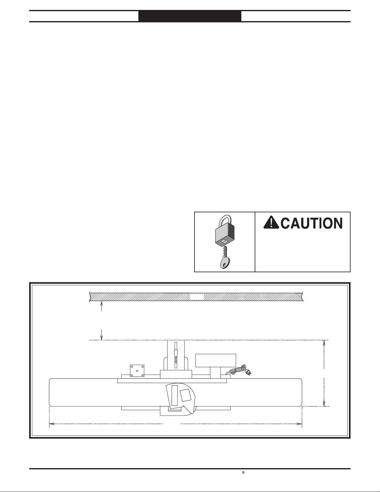
Min. 30"
for Maintenance
Figure 12. Minimum working clearances. Minimum working clearances.
Children or untrained
people may be seriously
87½"
Wall
injured by this machine.
Only install in an access
restricted location.
39"
-17-

South Bend Tools
Model SB1113
PREPARATION
Assembly
The machine must be fully assembled before it
can be operated. Before beginning the assembly
process, refer to Required for Setup on
Page 12 and gather all listed items. To ensure
the assembly process goes smoothly, first clean
any parts that are covered or coated in heavyduty rust preventative (if applicable).
This machine and its
parts are heavy! Serious
personal injury may occur
if safe moving methods are
not used. To reduce the
risk of a lifting or dropping
injury, ask others for help
and use power equipment.
For Machines Mfd. Since 05/23
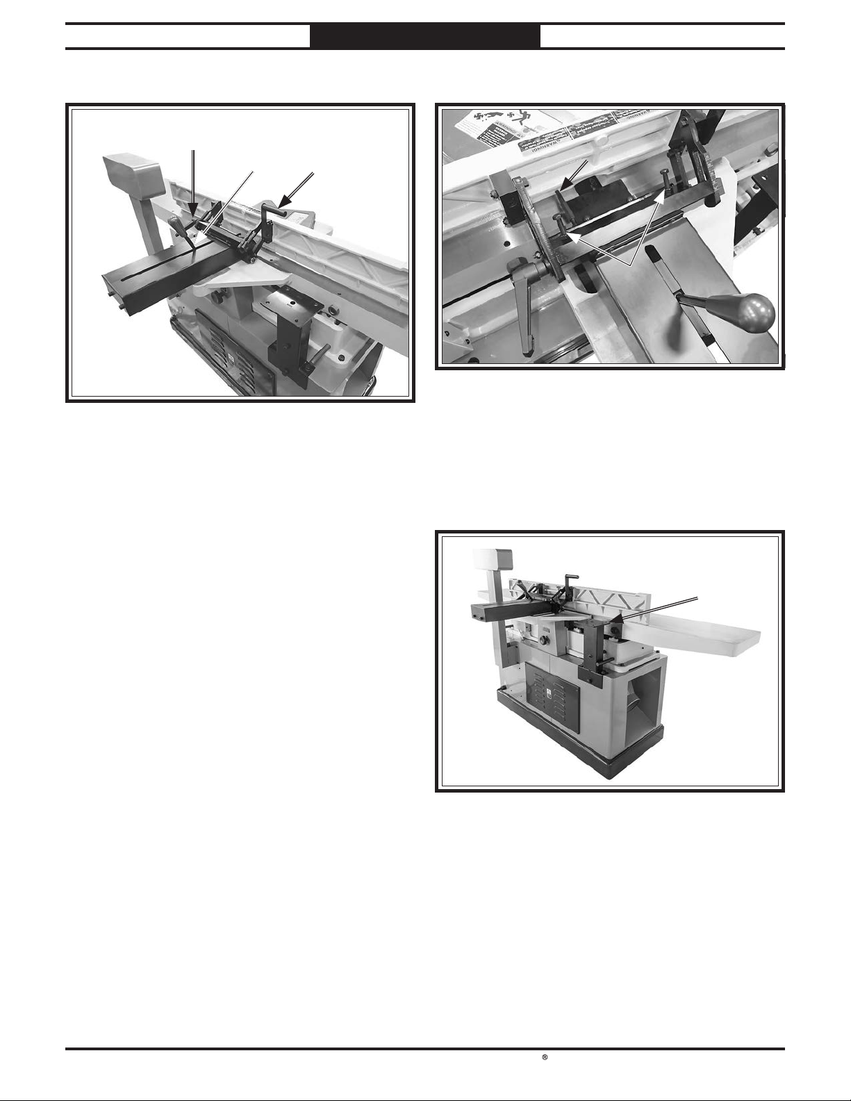
5. Remove (4) cap screws, flat washers, and lock
washers securing control panel column, rotate
column vertically, then re-install fasteners
(see Figure 13).
Note: Be careful not to damage control panel
cord during installation.
Control PanelControl Panel
ColumnColumn
DO NOT lift this jointer by the tables. Doing so
may affect factory-set table parallelism. Attach
lifting straps to lifting bars.
The Model SB1113 requires the use of lifting
equipment such as a forklift, engine hoist, or
boom crane. DO NOT attempt to lift or move
jointer without necessary assistance from other
people. Each piece of lifting equipment must be
rated for at least 1200 lbs. to support dynamic
loads that may be applied while lifting.
Review Power Supply Requirements on
Page 13, then prepare a permanent location
for the jointer.
To assemble jointer:
1. Move jointer to desired location.
2. Remove crate top and sides, then remove any
blocks around machine base.
3. Remove any plastic wrap around machine
and components.
x 4
Figure 13. Rotating control panel column. Rotating control panel column.
Unbolt jointer from pallet.
6.
7. Wrap lifting straps around lifting bars, as
shown in Figure 14.
Lifting BarsLifting Bars
Figure 14. Example of jointer supported evenly at Example of jointer supported evenly at
lifting bars by lifting straps.lifting bars by lifting straps.
With lifting straps positioned evenly on forks
8.
or crane, lift jointer off of pallet and place it
in desired location.
4. Set fence to 90° and move it all the way
forward.
-18 -
Verify all indexable inserts are securely
9.
tightened on cutterhead.

South Bend Tools
For Machines Mfd. Since 05/23 Model SB1113
10.
Verify outfeed table height is set correctly
with inserts at top dead center (TDC) as
shown in Setting Outfeed Table Height
on Page 40.
PREPARATION
Dust Collection
Set fence to 90° and move it all the way back.
11.
Loosen shaft lock and insert guard shaft into
12.
mounting hole, positioned so guard rests
against fence (see Figure 15).
FenceFence
Shaft LockShaft Lock
CutterheadCutterhead
GuardGuard
Figure 15. Installing cutterhead guard. Installing cutterhead guard.
Position guard height as low as possible
13.
without dragging on infeed table/rabbeting
ledge (approximately
then tighten shaft lock.
1
⁄16" above infeed table),
DO NOT operate the Model SB1113 without
an adequate dust collection system. This
jointer creates substantial amounts of wood
dust while operating. Failure to use a dust
collection system can result in short and longterm respiratory illness.
Recommended CFM at Dust Port: 850 CFM
Do not confuse this CFM recommendation with
the rating of the dust collector. To determine
the CFM at the dust port, you must consider
these variables: (1) CFM rating of the dust
collector, (2) hose type and length between the
dust collector and the machine, (3) number of
branches or wyes, and (4) amount of other open
lines throughout the system. Explaining how to
calculate these variables is beyond the scope of
this manual. Consult an expert or purchase a
good dust collection "how-to" book.
To connect machine to a dust collector:
1. Fit a 6" dust hose that is connected to a dust
collector over dust port, and secure in place
with a hose clamp (see Figure 16).
The cutterhead guard is a critical safety
feature of this jointer. You MUST verify its
operation before using the jointer! Failure to
properly install this guard will greatly increase
risk of serious personal injury.
Verify proper operation of cutterhead guard
14.
by setting fence to 90°, moving fence to
rear of table, then pulling cutterhead guard
back and letting it go. It should spring back
over cutterhead and contact fence without
dragging across outfeed table.
— If cutterhead guard DOES NOT spring
back over cutterhead and contact fence,
or if it drags across outfeed table, then
it must be adjusted (refer to Checking/
Adjusting Cutterhead Guard on
Page 41 for instructions).
Figure 16. Example of Example of dust hose attached to dust port.dust hose attached to dust port.
2.
Tug hose to make sure it does not come off.
Note: A tight fit is necessary and ensures
proper performance during operation.
-19 -

South Bend Tools
Model SB1113
PREPARATION
For Machines Mfd. Since 05/23
Digital Readout Batteries
You must install two AAA batteries in the
battery compartment for the digital readout
(DRO) to function.
To install AAA batteries in digital readout:
1. Remove cover on battery compartment (see
Figure 17).
Battery CompartmentBattery Compartment
Test Run
After all preparation steps have been completed,
the machine and its safety features must be
tested to ensure correct operation. If you discover
a problem with the operation of the machine or
its safety components, do not operate it further
until you have resolved the problem.
Note: Refer to Troubleshooting on Page 46
for solutions to common problems that occur with
all jointers. If you need additional help, contact
our Tech Support at (360) 734-1540.
The test run consists of verifying the following:
• Motor powers up and runs correctly.
• Emergency Stop and Knee Stop buttons work
correctly.
Serious injury or death can result from using
this machine BEFORE understanding its
controls and related safety information. DO
NOT operate, or allow others to operate,
machine until the information is understood.
Figure 17. Digital readout battery compartment. Digital readout battery compartment.
Insert included AAA batteries, then re-
2.
install cover.
DO NOT start machine until all preceding
setup instructions have been performed.
Operating an improperly set up machine may
result in malfunction or unexpected results
that can lead to serious injury, death, or
machine/property damage.
To test run machine:
1. Clear away all tools and objects used during
assembly and preparation.
Connect machine to power source. POWER
2.
light should illuminate,
— If light does not illuminate, check power
connection.
-20-

South Bend Tools
For Machines Mfd. Since 05/23 Model SB1113
PREPARATION
3. Push EMERGENCY STOP button in, then
twist it clockwise so it pops out. When
EMERGENCY STOP button pops out,
button is reset and ready for operation (see
Figure 18).
I
S
W
T
T
EMERGENCY
STOP
EMERGENCY STOP
Button
Figure 18. Resetting EMERGENCY STOP button.Resetting EMERGENCY STOP button.
Push START button to turn machine ON.
4.
Verify machine operates smoothly without
unusual problems or noises.
— When operating correctly, machine runs
smoothly with little or no vibration or
rubbing noises.
— Investigate and correct strange or
unusual noises or vibrations before
operating machine further. ALWAYS
disconnect machine from power when
investigating or correcting potential
problems.
Press EMERGENCY STOP button to stop
5.
machine.
WITHOUT resetting EMERGENCY STOP
6.
button, press START button. Machine should
not start.
Reset EMERGENCY STOP button, and push
7.
START button.
Press Knee Stop button to stop machine.
8.
— If machine does stop, Knee Stop button
safety feature is working correctly.
— If machine does not stop, (with Knee Stop
button pushed in), immediately disconnect
power to machine. The Knee Stop button
safety feature is not working correctly.
This safety feature must work properly
before proceeding with regular operations.
Call Tech Support for help.
Inspections & Adjustments
The following list of adjustments were performed
at the factory before your machine was shipped:
• Table Parallelism.........................(Page 35)
• Calibrating Depth Scale.............(Page 39)
• Outfeed Table Adjustment ........(Page 40)
• Fence Stop Settings ....................(Page 42)
• V-Belt Tension Adjustment .......(Page 44)
Be aware that machine components can shift
during the shipping process. Pay careful
attention to these adjustments as you test run
your machine. If you find that the adjustments
are not set according to the procedures in this
manual or your personal preferences, re-adjust
them.
— If machine does not start, EMERGENCY
STOP button safety feature is working
correctly.
— If machine does start (with EMERGENCY
STOP button pushed in), immediately
disconnect power to machine. The
EMERGENCY STOP button safety
feature is not working correctly. This
safety feature must work properly before
proceeding with regular operations. Call
Tech Support for help.
-21-

The purpose of this overview is to provide
the novice machine operator with a basic
understanding of how the machine is used during
operation, so they can more easily understand
the controls discussed later in this manual.
Note:
it is not intended to be an instructional guide
for performing actual machine operations.
To learn more about specific operations and
machining techniques, seek training from people
experienced with this type of machine, and do
additional research outside of this manual by
reading "how-to" books, trade magazines, or
websites.
South Bend Tools
Model SB1113
OPERATION
For Machines Mfd. Since 05/23
Operation Overview
Due to the generic nature of this overview,
To reduce the risk of
serious injury when using
this machine, read and
understand this entire
manual before beginning
any operations.
To complete a typical operation, the operator
does the following:
1. Examines workpiece to verify it is safe and
suitable for cutting.
Adjusts fence for width of workpiece and
2.
locks it in place.
Adjusts fence tilt, if necessary.
3.
Adjusts infeed table height to set depth of
4.
cut per pass.
Puts on safety glasses, respirator, and any
5.
other required protective equipment.
Starts jointer.
6.
Using push blocks as needed, holds
7.
workpiece firmly against infeed table and
fence, and feeds workpiece into cutterhead
at a steady and controlled rate until entire
length of workpiece has been cut and it
clears the cutterhead on the outfeed table
side.
Repeats cutting process described above
8.
until desired results are achieved.
To reduce risk of eye injury
from flying chips or lung
damage from breathing dust,
always wear safety glasses
and a respirator when
operating this machine.
Stops jointer.
9.
-22-

South Bend Tools
For Machines Mfd. Since 05/23 Model SB1113
Stock Inspection & Requirements
OPERATION
• Scrape all glue off the workpiece before
jointing. Glue deposits on the workpiece,
hard or soft, will gum up the cutterhead and
produce poor results.
Follow these rules when choosing and
jointing stock:
• DO NOT joint or surface plane stock that
contains large or loose knots. Injury to the
operator or damage to the workpiece can
occur if a knot becomes dislodged during the
cutting operation.
• DO NOT joint or surface plane against the
grain direction. Cutting against the grain
increases the likelihood of kickback, as well
as tear-out on the workpiece.
• Jointing and surface planing with the grain
produces a better finish and is safer for the
operator. Cutting with the grain is described
as feeding the stock on the jointer so the grain
points down and toward you as viewed on the
edge of the stock (see Figure 19).
Note: If the grain changes direction along the
edge of the board, decrease the cutting depth
and make additional passes.
CORRECT
ROTATION
OUTFEED TABLE
FEED DIRECTION
INFEED TABLE
• Remove foreign objects from the workpiece.
Make sure that any stock you process with
the jointer is clean and free of dirt, nails,
staples, tiny rocks or any other foreign
objects that could damage the cutterhead.
These particles could also cause a spark as
they strike the cutterhead and create a fire
hazard.
IMPORTANT: Wood stacked on a concrete or
dirt surface can have small pieces of concrete
or stone pressed into the surface.
• Make sure all stock is sufficiently dried
before jointing. Wood with a moisture
content over 20% will cause unnecessary
wear on the cutters and poor cutting results.
Excess moisture can also hasten rust and
corrosion.
Make sure your workpiece exceeds the
minimum dimension requirements shown
below before processing it through the jointer,
or the workpiece may break or kick back
during the operation.
With Grain
INCORRECT
ROTATION
OUTFEED TABLE
Figure 19. Proper grain alignment with cutterhead. Proper grain alignment with cutterhead.
• Only cut natural wood. This jointer is only
designed for cutting natural wood stock.
Never use it to cut MDF, particle board,
plywood, laminates, drywall, backer board,
metals, glass, stone, tile, products with leadbased paint, or products that contain asbestos.
Cutting these may lead to injury or machine
damage.
FEED DIRECTION
INFEED TABLE
Against Grain
Edge Jointing
¾" Min.
¼" Min.
Surface Planing
½" Min.
Figure 20. Minimum stock dimensions for jointer.Minimum stock dimensions for jointer.
10" Min.
10" Min.
¾" Min.
-23-
South Bend Tools
Model SB1113
OPERATION
Squaring Stock
Squaring stock means making it flat and parallel
along both length and width, and making the
length and width perpendicular to one another.
The purpose of squaring stock is to prepare it for
accurate cuts and construction later on.
A properly "squared up" workpiece is essential
for tasks such as accurate table saw cuts, glueups/laminations, cutting accurate bevels on a
bandsaw, and many other applications where
one surface of a workpiece is used to reference
another.
Items Needed Qty
Table Saw .............................................................. 1
Jointer
Planer
....................................................................1
....................................................................1
For Machines Mfd. Since 05/23
Surface Plane on a Thickness Planer—
2.
Opposite face of workpiece is surface planed
flat with a thickness planer.
Previously Surface
Planed Face
3. Edge Joint on Jointer—Concave edge of
workpiece is jointed flat with jointer.
Squaring stock involves four steps
performed in the order below:
1. Surface Plane on Jointer—Concave face of
workpiece is surface planed flat with jointer.
Rip Cut on a Table Saw—Jointed edge of
4.
workpiece is placed against a table saw fence
and opposite edge cut off.
Previously
Jointed
45
30
15
Edge
-24-

South Bend Tools
For Machines Mfd. Since 05/23 Model SB1113
OPERATION
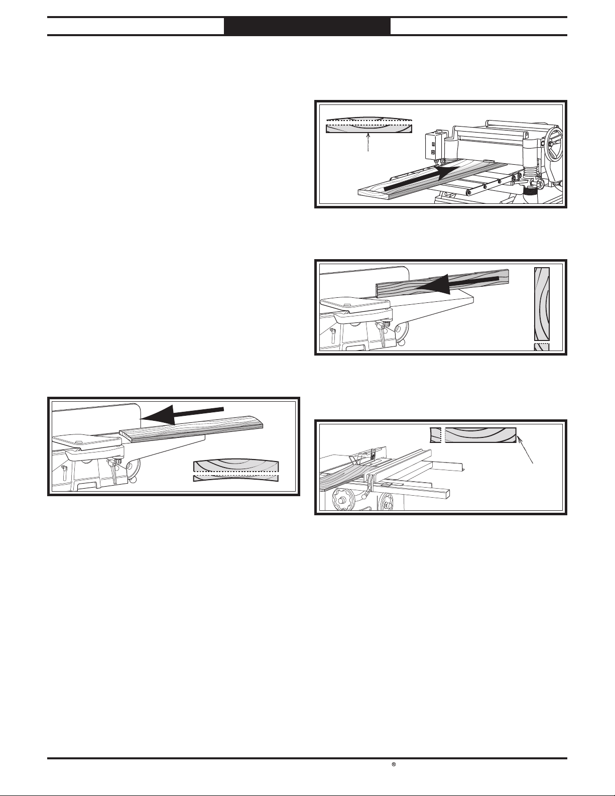
Surface Planing
The purpose of surface planing (see example
Figures below) on the jointer is to make one flat
face on a piece of stock to prepare it for thickness
planing on a planer
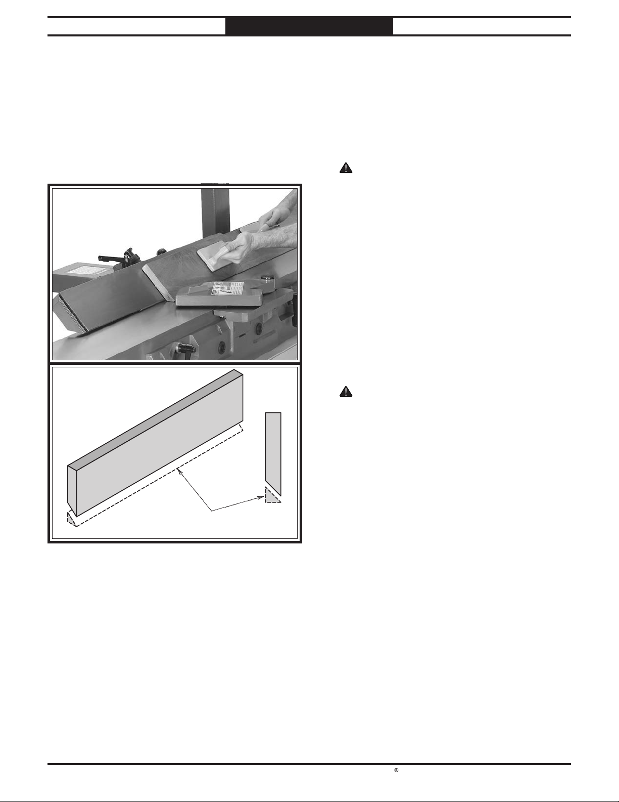
Failure to use push blocks when surface
planing could result in your hands contacting
rotating cutterhead, which will cause serious
personal injury. Always use push blocks when
surface planing on jointer!
.
To surface plane on jointer:
1. Inspect stock to ensure it is safe and suitable
for the operation (see Stock Inspection &
Requirements on Page 23).
Set infeed table height to desired cutting
2.
depth for each pass.
CAUTION: To minimize risk of kickback,
do not exceed a cutting depth of
when surface planing.
Set fence to 90°.
3.
Start jointer.
4.
5. Place workpiece firmly against fence and
infeed table.
CAUTION: To ensure workpiece remains
stable during cut, concave sides of workpiece
must face toward table and fence.
1
⁄16" per pass
Removed
Surface
Figure 21. Example of a surface planing operation.Example of a surface planing operation.
Feed workpiece completely across cutterhead
6.
while keeping it firmly against fence and
tables during the entire cut.
CAUTION: Keep hands at least 4"
away from cutterhead during the entire
cut. Instead of allowing a hand to pass
directly over cutterhead, lift it up and
over cutterhead, and safely reposition it
on the outfeed side to continue supporting
workpiece. Use push blocks whenever
practical to further reduce risk of accidental
hand contact with cutterhead.
Repeat Step 6 until entire surface is flat.
7.
Tip: When squaring up stock, cut opposite
side of workpiece with a planer instead of the
jointer to ensure both sides are parallel.
-25-

South Bend Tools
Model SB1113
OPERATION
For Machines Mfd. Since 05/23
Edge Jointing
Edge jointing (see example Figures below)
produces a flat and true surface along the side of
a workpiece by removing uneven areas. It is an
essential step for squaring up warped or rough
stock and when preparing a workpiece for joinery
or finishing.
To edge joint on jointer:
1. Inspect stock to ensure it is safe and suitable
for the operation (see Stock Inspection &
Requirements on Page 23).
Set infeed table height to desired cutting
2.
depth for each pass.
CAUTION: To minimize risk of kickback,
do not exceed a cutting depth of
Set fence to 90°.
3.
Start jointer.
4.
5. Place workpiece firmly against fence and
infeed table.
CAUTION: To ensure workpiece remains
stable during cut, concave sides of workpiece
must face toward table and fence.
Feed workpiece completely across cutterhead
6.
while keeping it firmly against fence and
tables during the entire cut.
1
⁄8" per pass.
Removed
Surface
Figure 22. Example of an edge jointing operation.Example of an edge jointing operation.
CAUTION: Keep hands at least 4"
away from cutterhead during the entire
cut. Instead of allowing a hand to pass
directly over cutterhead, lift it up and
over cutterhead, and safely reposition it
on the outfeed side to continue supporting
workpiece. Use push blocks whenever
practical to further reduce risk of accidental
hand contact with cutterhead.
Repeat Step 6 until the entire edge is flat.
7.
Tip: When squaring up stock, cut opposite
edge of workpiece with a table saw instead
of the jointer—otherwise, both edges of
workpiece will not be parallel with each
other.
-26-
South Bend Tools
For Machines Mfd. Since 05/23 Model SB1113
OPERATION
Bevel Cutting
Bevel cuts (see example Figures below) can be
made by setting the fence at the desired angle
and feeding the workpiece firmly along the fence
face, with the bottom inside corner firmly against
the table. The cutting process typically requires
multiple passes or cuts to bevel the entire edge of
a workpiece.
To bevel cut on jointer:
1. Inspect stock to ensure it is safe and suitable
for the operation (see Stock Inspection &
Requirements on Page 23).
Set infeed table height to cutting depth
2.
desired for each pass.
CAUTION: Cutting depth for bevel cuts is
typically between
hardness and width of stock.
Set fence tilt to desired angle of cut.
3.
Place workpiece against fence and infeed
4.
table with concave side face down.
Start jointer.
5.
6. With a push block in your leading hand,
press workpiece against table and fence
with firm pressure, and feed workpiece over
cutterhead with a push block in your trailing
hand.
1
⁄16" and 1⁄8", depending on
Removed
Surface
Figure 23. Example of fence set up for a bevel cut of Example of fence set up for a bevel cut of
45° outward (135º).45° outward (135º).
CAUTION: When your leading hand gets
within 4" of the cutterhead, lift it up and
over cutterhead, and place push block on
portion of the workpiece once it is 4" past
cutterhead. Now, focus your pressure on
outfeed end of the workpiece while feeding,
and repeat same action with your trailing
hand when it gets within 4" of cutterhead. To
help keep your hands safe, DO NOT let them
get closer than 4" from moving cutterhead at
any time during operation!
Repeat cutting process, as necessary, until
7.
you are satisfied with the results.
-27-
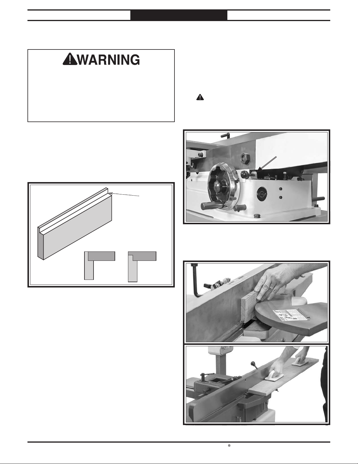
South Bend Tools
Model SB1113
OPERATION
For Machines Mfd. Since 05/23
Rabbet Cutting
When cutterhead guard is removed,
attempting any other cut besides a rabbet
directly exposes operator to moving
cutterhead. To minimize risk of injury, always
keep cutterhead guard installed when
possible, and ALWAYS immediately replace it
after performing rabbet cuts.
A rabbet cut removes a portion of a workpiece
edge, so it fits together with an opposing, equally
sized rabbet cut on another workpiece (see
example Figure below). This is a classic method
of joining two workpieces that is simple, yet
strong.
Removed
Surface
To rabbet cut on jointer:
1. Inspect stock to ensure it is safe and suitable
for the operation (see Stock Inspection &
Requirements on Page 23).
Set infeed table height to desired cutting
2.
depth for each pass.
CAUTION: Infeed table depth stop
restricts infeed table maximum depth-of-cut
1
⁄8". Pull knob (see Figure 24) to set infeed
to
table depth-of-cut between
1
⁄8"–3⁄4".
Infeed TableInfeed Table
Depth StopDepth Stop
Rabbet Joints
This jointer can be used to make high-quality
rabbet cuts, but there are some situations—
whether it is due to an excessively large/small
workpiece size or rabbet cutting width/depth—
when it will not be safe or appropriate for
making the rabbet cut on this jointer. In these
cases, you need to use another tool or method for
rabbet cutting that will be a safer alternative.
Typically, rabbet cutting with a jointer requires
the cutterhead guard to be removed first, so
the workpiece can slide along the rabbeting
ledge during the cut. However, it is possible to
make rabbet cuts with workpieces up to 1" thick
without removing the cutterhead guard. This
is done by performing the rabbet cut with the
workpiece on end (similar to when you are edge
jointing).
Figure 24. Location of infeed table depth stop. Location of infeed table depth stop.
3.
Remove cutterhead guard if necessary to
perform operation (see Figure 25).
Guard InstalledGuard Installed
Guard RemovedGuard Removed
Figure 25. Example of rabbet cutting operations.Example of rabbet cutting operations.
-28-

South Bend Tools
For Machines Mfd. Since 05/23 Model SB1113
Set fence to 90° and near front of jointer,
4.
so amount of exposed cutterhead in front of
fence matches size of desired rabbet.
Start jointer.
5.
OPERATION
Setting Depth of Cut
The depth of cut on a jointer affects the amount
of material removed from the bottom of the
workpiece as it passes over the cutterhead.
6. Place workpiece firmly against fence and
infeed table.
CAUTION: To ensure workpiece remains
stable during cut, concave sides of workpiece
must face toward table and fence.
Feed workpiece completely across cutterhead
7.
while keeping it firmly against fence and
tables during entire cut.
CAUTION: Keep hands at least 4"
away from cutterhead during the entire
cut. Instead of allowing a hand to pass
directly over cutterhead, lift it up and
over cutterhead, and safely reposition it
on the outfeed side to continue supporting
workpiece. Use push blocks whenever
practical to further reduce risk of accidental
hand contact with cutterhead.
Repeat Step 7 until rabbet is cut to depth.
8.
The depth of cut is set by adjusting the height of
the infeed table relative to the outfeed table and
cutterhead inserts at top dead center (TDC).
DO NOT exceed 1⁄8 " cut per pass on this
machine or the risk of kickback and serious
injury will be greatly increased!
To set depth of cut on jointer:
1. Loosen infeed table lock and rotate
handwheel until depth scale on front of
jointer (see Figure 26) indicates desired
depth of cut.
Note: The depth scale can be calibrated
or "zeroed" if it is not accurate (refer to
Calibrating Infeed Table Depth Scale on
Page 39).
Re-install cutterhead guard if removed in
9.
Step 3.
Figure 26. Model SB1113 depth scale. Model SB1113 depth scale.
Set infeed table positive stops (refer to
2.
Setting Infeed Table Positive Stops on
Page 39).
Tighten infeed table lock before beginning
3.
jointer operations.
-29-

order online at www.grizzly.com or call 1-800-523-4777
South Bend Tools
Model SB1113
ACCESSORIES
Accessories
This section includes the most common
accessories available for your machine, which
are available through our exclusive dealer,
Grizzly Industrial, Inc., at grizzly.com.
Installing unapproved accessories may
cause machine to malfunction, resulting in
serious personal injury or machine damage.
To reduce this risk, only install accessories
recommended by South Bend or Grizzly.
Refer to Grizzly's website or latest catalog for
additional recommended accessories.
For Machines Mfd. Since 05/23
W1036—Clear Flexible Hose 6" x 10'
H7217—Rigid Flex Industrial Hose 6" x 5'
G7367—45° Industrial Elbow 6"
G7369—90° Industrial Elbow 6"
H5297—6" Industrial Dust Collection Starter Kit
T26508—6" Industrial Joist Hanger
W1319—Wire Hose Clamp 6"
W1009—Plastic Blast Gate 6"
G7358—Industrial Blast Gate 6"
W1053—Anti-Static Grounding Kit
We've hand picked a selection of commonly used
dust collection components for machines with 6"
dust ports.
H7217H7217
T28206—GRR-RIP Block Smart Pushblock
The GRR-RIP Block features auto-retracting
heel technology that hooks to the tail end of
your board. The green GRR-RIP provides an
unparalleled hold on your work piece. The
ergonomic handle exerts directional pressure
against the fence, so it stays right where you
need it to.
W1036W1036
G7369G7369 W1053W1053
Figure 28. Dust collection accessories.
H9893—10 Pk. Carbide Inserts 15 x 15 x 2.5mm
G7358G7358
G7367G7367
Figure 27. Model T28206 GRR-RIP Block.Model T28206 GRR-RIP Block.
Figure 29. H9893 Replacement Carbide Inserts. H9893 Replacement Carbide Inserts.
-30-

order online at www.grizzly.com or call 1-800-523-4777
South Bend Tools
For Machines Mfd. Since 05/23 Model SB1113
ACCESSORIES
T30024—Powered Respirator Kit
Breathing wood dust could cause severe
respiratory illnesses. This kit is a lightweight,
comfortable, and easy-to-carry device for
protecting the airway from small particulates.
Figure 30. T30024 Powered Respirator Kit.T30024 Powered Respirator Kit.
T23246—The Missing Shop Manual: Jointer
Dedicated to providing integral information
about woodworking tools and techniques that
other manuals overlook, the books in this series
contain safety facts, explanations about basic
project set-up, and tips for best performance.
T32323—Woodturners Face Shield
T32401—EDGE Brazeau Safety Glasses, Clear
T32402—EDGE Khor G2 Safety Glasses, Tint
T32404—EDGE Mazeno Safety Glasses, Clear
T32301T32301T32323T32323
T32402T32402
Figure 32. Assortment of basic eye protection.
W1050—Dust Collection Basics Book
This incisive book skillfully guides the
woodworker through all the steps necessary in
the design and construction of an efficient central
dust collection system and tells you what you
need to know for easy installation. The text offers
practical hints and techniques and takes the
mystery, misery and hype away from a subject
that should be as clear as the air you breathe. 64
pages of concise, carefully illustrated text.
T32404T32404
Figure 31. T23246 Missing Shop Manual.T23246 Missing Shop Manual.
Figure 33. W1050 Dust Collection Basics.W1050 Dust Collection Basics.
-31-

order online at www.grizzly.com or call 1-800-523-4777
South Bend Tools
Model SB1113
ACCESSORIES
For Machines Mfd. Since 05/23
SB1365—South Bend Way Oil-ISO 68
Engineered for the high pressure exerted on
horizontal or vertical ways and slides. Protects
against rust and corrosion. Ensures stick-free,
smooth motion which maximizes finishes and
extends the life of your machine. Won’t gum up!
12 oz. AMGA#2 (ISO 68 Equivalent).
Figure 34. SB1365 Way Oil. SB1365 Way Oil.
SB1099—3 HP Cyclone Dust Collector
The Model SB1099 features a 3 HP motor, a
whopping 1860 CFM of airflow capacity, and
a 52-gallon collection capacity. It's packed
with features like a built-in sound muffler, an
automatic filter paddle brush for easy cleaning, a
remote-controlled magnetic switch, and a quickrelease lift handle for easy sawdust disposal.
G0826—Easy Feeder Power Feeder
This all-purpose, heavy-duty power feeder is
perfect for use with jointers and shapers, and
has a
efficiency, high-torque, and variable-speed feed
control from a single-phase power supply.
2
⁄3 HP BLDC motor that provides energy-
Figure 35. Model G0826 Power Feeder. Model G0826 Power Feeder.
Figure 36. Model SB1099 3 HP Cyclone Dust Model SB1099 3 HP Cyclone Dust
Collector.Collector.
-32-

!
South Bend Tools
For Machines Mfd. Since 05/23 Model SB1113
MAINTENANCE
Maintenance Schedule
Always disconnect
machine from power before
performing maintenance or
serious personal injury may
result.
For optimum performance from your machine,
follow this maintenance schedule and refer to
any specific instructions given in this section.
To minimize your risk of injury and maintain
proper machine operation, shut down the
machine immediately if you ever observe any
of the items below, and fix the problem before
continuing operations:
Ongoing
• Check/correct loose mounting bolts.
• Check/correct damaged or dull cutterhead
inserts.
• Check/correct worn or damaged wires.
• Check/correct proper height adjustment and
function of cutterhead guard.
• Clean/protect unprotected cast-iron surfaces.
• Clean dust or debris around machine.
• Correct any other unsafe condition.
Monthly
• Clean and lubricate fence pivot points.
V-belt tension, damage, or wear.
•
Clean/vacuum dust buildup from inside
•
stand and off of motor.
Replace batteries in control panel digital
•
readout as needed.
Unpainted Cast Iron
Protect the unpainted cast iron surfaces on the
table by wiping the table clean after every use—
this ensures moisture from wood dust does not
remain on bare metal surfaces. Keep tables rustfree with regular applications of products like
South Bend SB1365 Way Oil (see Page 32).
Bare metal surfaces can quickly develop surface
rust if not coated. Machinery stored near
windows in direct sunlight or where paints,
thinners, or certain gasses are open to the air
can experience bleaching, discoloring of paint or
yellowing of clear plastic guards.
Lubrication
Since all bearings on the Model SB1113 are
sealed and permanently lubricated, simply leave
them alone until they need to be replaced. DO
NOT lubricate them.
Below is a list of components that require
periodic lubrication. Be careful not to overlubricate these components. Large amounts of
lubricant will attract sawdust, causing the metal
components to gum up and bind.
Fence: Place 1–2 drops of light machine oil on the
fence pivot points (see Figure 37) as needed.
Cleaning
Cleaning the Model SB1113 is relatively easy.
Vacuum excess wood chips and sawdust, and
wipe off the remaining dust with a dry cloth. If
any resin has built up, use a resin dissolving
cleaner to remove it. Treat all unpainted cast
iron and steel with a non-staining lubricant after
cleaning.
Figure 37. Fence lubrication locations.Fence lubrication locations.
-33-

South Bend Tools
Model SB1113
Fence Pistons: Place 1–2 drops of light machine
oil on a clean, cloth rag, then wipe exposed
surface of fence pistons (see Figure 38). Unlock
fence and move back-and-forth through entire
range of motion as needed.
Figure 38. Fence pistons lubrication locations.Fence pistons lubrication locations.
Gears: Use a small brush to apply multi-purpose
grease to handwheel worm gear shafts and gears.
MAINTENANCE
For Machines Mfd. Since 05/23
Machine Storage
All machinery will develop serious rust problems
and corrosion damage if it is not properly
prepared for storage. If decommissioning this
machine, use the steps in this section to ensure
that it remains in good condition.
To prepare your machine for storage or
decommission it from service:
1. DISCONNECT MACHINE FROM POWER!
2. Thoroughly clean all unpainted, bare metal
surfaces, then coat them with a lightweight
grease or rust preventative. Take care to
ensure these surfaces are completely covered
but that the grease or rust preventative is
kept off of painted surfaces.
Note: If the machine will be out of service for
only a short period of time, use way oil or a
good grade of medium-weight machine oil
(not auto engine oil) in place of the grease or
rust preventative.
If the machine has belts, loosen or remove
3.
them so they do not become stretched while
the machine is not in use.
Completely cover the machine with a tarp
4.
or plastic sheet that will keep out dust and
resist liquid or moisture. If machine will be
stored in/near direct sunlight, use a cover
that will block the sun's rays.
-34-

!
South Bend Tools
For Machines Mfd. Since 05/23 Model SB1113
Checking/Adjusting Table Parallelism
If the tables are not parallel with the cutterhead
or each other, then poor cutting results and
kickback can occur.
Tools Needed: Qty
Heavy Leather Gloves ...................................1 Pair
Straightedge 36"
Wrench or Socket 12mm
Wrench or Socket 32mm
Adjustable Wrench 10"
Hex Wrench 4mm
Duct Tape
Electrical Parts Cleaner
..............................................................1
....................................................1
...................................... 1
....................................... 1
.........................................1
.................................................1
.......................................1
SERVICE
5. Place straightedge on outfeed table so it
hangs over cutterhead, then lower outfeed
table until straightedge just touches
cutterhead body, as shown in Figure 40
(rotate cutterhead if necessary).
Straightedge
Outfeed Table
Figure 40. Adjusting outfeed table even with Adjusting outfeed table even with
cutterhead body.cutterhead body.
Checking Outfeed Table
Place straightedge in positions shown in
1. DISCONNECT MACHINE FROM POWER!
2. Put on heavy leather gloves.
6.
Figure 41. In each position, straightedge
should touch cutterhead body and sit flat on
outfeed table.
3. Remove cutterhead guard and fence.
4. Loosen outfeed table lock located at front of
machine, then loosen jam nuts and positive
stop bolts located under outfeed table (see
Figure 39).
Stop BoltsStop Bolts
Jam NutJam Nut
Jam NutJam Nut
Figure 39. Outfeed table positive stop bolts.Outfeed table positive stop bolts.
Black Lines Represent
Straightedge Positions
From Overhead View
Figure 41. Straightedge positions for verifying if Straightedge positions for verifying if
outfeed table is parallel with cutterhead.outfeed table is parallel with cutterhead.
— If straightedge touches cutterhead and
sits flat across outfeed table in each
position, then outfeed table is already
parallel with cutterhead. Check infeed
table to make sure that it is parallel with
outfeed table.
— If straightedge does not touch cutterhead
and sit flat on outfeed table in any
positions, then outfeed table is not
parallel with cutterhead. Correct outfeed
table parallelism, then correct infeed table
parallelism.
-35-

South Bend Tools
Model SB1113
SERVICE
For Machines Mfd. Since 05/23
Checking Infeed Table
1. Follow all steps for checking outfeed table
parallelism to make sure that outfeed table
is parallel with cutterhead.
Raise outfeed table higher than cutterhead.
2.
3. Loosen infeed table jam nuts and positive
stop bolts shown in Figure 42.
Stop BoltsStop Bolts
Jam NutsJam Nuts
Figure 42. Infeed table positive stop bolts.Infeed table positive stop bolts.
Black Lines Represent
Straightedge Positions
from Overhead View
Figure 44. Straightedge positions for checking infeed/Straightedge positions for checking infeed/
outfeed table parallelism.outfeed table parallelism.
— If straightedge sits flat against both
infeed and outfeed table in each positions,
then tables are parallel. Set both table
heights (Pages 39–40) and replace
cutterhead guard.
— If straightedge does not sit flat against
both infeed and outfeed table in any
positions, then follow Adjusting Table
Parallelism.
Place straightedge halfway across infeed
4.
table and halfway over outfeed table, and
adjust infeed table even with outfeed table,
as shown in Figure 43.
Straightedge
Outfeed Table Infeed Table
Figure 43. Infeed and outfeed tables set evenly.Infeed and outfeed tables set evenly.
Place straightedge in positions shown in
5.
Figure 44. In each position, straightedge
should sit flat against both outfeed table and
infeed table.
Adjusting Table Parallelism
For safe and proper cutting results, tables must
be parallel to cutterhead. Adjusting them to be
parallel is a task of precision and patience, and
may take up to one hour to complete. This is a
permanent adjustment and should not need to be
repeated for the life of the machine.
Due to the complex nature of this task, we
recommend that you double check current table
positions to verify that they need to be adjusted
before starting.
The tables have four eccentric bushings under
each corner that allow the tables to be adjusted
parallel. These eccentric bushings are locked in
place by set screws and adjust when rotated.
The correct order for adjusting the table
parallelism is to first adjust the outfeed table
parallel with the cutterhead to within 0.010"-
0.012", then adjust the infeed table parallel with
the outfeed table.
-36-
When setting the outfeed table, all
measurements must be made from the
cutterhead body—NOT the inserts.

South Bend Tools
For Machines Mfd. Since 05/23 Model SB1113
IMPORTANT: The steps below are intended to be
performed in succession with the steps involved
in checking the outfeed table. DO NOT proceed
until those steps are followed.
SERVICE
To adjust table parallelism:
1. Place straightedge on outfeed table so it
hangs over cutterhead, then lower outfeed
table until straightedge just touches
cutterhead body, as shown in Figure 40 on
Page 35 (rotate cutterhead if necessary).
Figure 46. Front eccentric bushings.Front eccentric bushings.
Remove screw cover (see Figure 45)
2.
covering each set screw on outfeed table.
Note: It may help to clean screw covers with
electrical parts cleaner. Push duct tape firmly
against cover, then pull straight up.
Loosen each set screw (see Figure 45) two
3.
turns.
Set ScrewSet Screw
(Out of View)(Out of View)
Screw CoverScrew Cover
Figure 45. Screw cover and set screw location.Screw cover and set screw location.
4. Place straightedge in one of the positions
shown in Figure 44 on Page 36, and
adjust table by turning eccentric bushings
(Figures 46–47) as needed with an
adjustable wrench so that straightedge
touches cutterhead while lying flat across
outfeed table. Repeat this step with each
remaining straightedge positions as many
times as necessary until outfeed table is
parallel with cutterhead to within 0.010"-
0.012".
Figure 47. Rear eccentric bushings.Rear eccentric bushings.
Tighten set screws and re-install screw
5.
covers on outfeed table.
Remove (4) screw covers on infeed table, and
6.
loosen set screws underneath two turns.
Place straightedge halfway across infeed
7.
table and halfway over outfeed table, then
adjust infeed table even with outfeed table,
as shown in Figure 48.
Straightedge
Outfeed Table Infeed Table
Note: Setting the outfeed table parallel to the
cutterhead within 0.010"-0.012" will produce
high quality results. Going lower than this
number will produce minimal gain.
Figure 48. Infeed and outfeed tables set evenly.Infeed and outfeed tables set evenly.
-37-

!
South Bend Tools
Model SB1113
Place straightedge in one of the positions
8.
shown in Figure 44 on Page 36, and
adjust eccentric bushings under infeed
table so straightedge lies flat against both
tables. Repeat this step with each remaining
straightedge position as many times as
necessary until infeed table is parallel with
outfeed table.
Tighten set screws and re-install covers on
9.
infeed table.
Set outfeed table height (refer to Setting
10.
Outfeed Table Height on Page 40).
Install fence and move it all the way back.
11.
12. Install cutterhead guard, tighten shaft
lock, then refer to Checking/Adjusting
Cutterhead Guard on Page 41.
SERVICE
The indexable inserts are very sharp and can
easily cut your hands. ALWAYS use caution
when handling these parts to reduce risk of
personal injury.
Item(s) Needed: Qty
Heavy Leather Gloves ...................................1 Pair
Indexable Inserts 15 x 15 x 2.5mm
Torx Head Screws T-25 #10-32 x
T-Handle Torx Driver T-25
Light Machine Oil
Clean Shop Rags
To rotate or change a carbide insert:
1. DISCONNECT MACHINE FROM POWER!
2. Set fence to 90° and move it all the way back.
For Machines Mfd. Since 05/23
...... As Needed
1
⁄2" .... As Needed
...................................1
................................. As Needed
................................... As Needed
Replacing Indexable Inserts
The helical-style cutterhead is equipped with
4-sided indexable carbide inserts. Each insert
can be removed, rotated, and re-installed to use
either of its four cutting edges. If one cutting edge
becomes dull or damaged, simply rotate it 90º (see
Figure 49) to use a sharp cutting edge.
The inserts have a reference dot on one corner.
The position of the reference dot on installed
inserts can be used to track which edges are
sharp/unused and which edges are dull or damaged. Replace inserts once the reference dot has
been rotated back to its original position.
Reference DotReference Dot
3. Loosen cutterhead guard shaft lock and
remove cutterhead guard.
Remove any sawdust from head of insert
4.
Torx screw.
Remove Torx screw and insert.
5.
6. Clean all dust and dirt off insert and
cutterhead pocket from which insert was
removed, and replace insert so a fresh, sharp
edge is facing outward.
Note: Proper cleaning is critical to achieving
a smooth finish. Dirt or dust trapped between
the insert and cutterhead will slightly raise
the insert, and make noticeable marks on
your workpieces the next time you cut.
Lubricate Torx screw threads with a light
7.
machine oil, wipe excess oil off threads, and
torque Torx screw to 48–50 in.-lbs.
Figure 49. Insert rotating sequence. Insert rotating sequence.
-38-
Note: Excess oil may squeeze between the
insert and cutterhead or in the screw hole,
thereby lifting the insert or screw slightly and
affecting workpiece finishes.
8. Install cutterhead guard, tighten shaft
lock, then refer to Checking/Adjusting
Cutterhead Guard on Page 41.

South Bend Tools
For Machines Mfd. Since 05/23 Model SB1113
SERVICE
Setting Infeed/Outfeed Table Positive Stops
The infeed and outfeed tables on the Model
SB1113 have positive stop bolts that, when
properly set up, allow the operator to quickly
adjust table height between finish/final cuts and
shaping/heavy cuts.
We recommend setting the minimum depth of
cut to
for most operations.
Each positive stop bolt (see Figure 50) controls
the top or bottom range of the table movement.
The jam nuts lock the positive stop bolts in
position so they won't move during operation.
1
⁄32" and the maximum depth of cut to 1⁄8 "
DO NOT exceed 1⁄8 " cut per pass on this
machine or the risk of kickback and serious
injury will be greatly increased!
Calibrating Infeed Table Depth Scale
The depth scale on the infeed table can be
calibrated or "zeroed" if it is not correct.
Tools Needed: Qty
Straightedge 36" ....................................................1
To calibrate depth scale on infeed table:
1. Set outfeed table height (refer to Setting
Outfeed Table Height on Page 40).
Move cutterhead guard out of the way.
2.
Place a straightedge across infeed and
3.
outfeed tables.
Adjust infeed table until it is level with
4.
outfeed table, as illustrated in Figure 51.
Top HeightTop Height
BottomBottom
HeightHeight
Jam NutsJam Nuts
Figure 50. Infeed/outfeed table positive stop bolts.Infeed/outfeed table positive stop bolts.
Straightedge
Outfeed Table Infeed Table
Figure 51. Infeed and outfeed tables set evenly. Infeed and outfeed tables set evenly.
-39-

!
South Bend Tools
Model SB1113
SERVICE
For Machines Mfd. Since 05/23
Setting Outfeed Table Height
The outfeed table height MUST be level with the
carbide inserts when they are at top-dead-center.
If the outfeed table is set too low, the workpiece
will be tapered from front to back. If the outfeed
table is set too high, the workpiece will hit
the edge of the outfeed table during operation,
increasing the chance of kickback.
To set outfeed table height:
1. DISCONNECT MACHINE FROM POWER!
2. Move cutterhead guard out of the way or
remove it, then remove belt guard.
Place a straightedge on outfeed table so
3.
it extends over cutterhead, and rotate
cutterhead pulley until one of the carbide
inserts is at top-dead-center (TDC), as shown
in Figure 52.
When correctly set, carbide insert will just
4.
touch straightedge when insert is at its
highest point of rotation (see Figure 52).
— If your outfeed table is correctly set, no
adjustments are necessary.
Tip: Some advanced woodworkers have found
that they can virtually eliminate snipe by
setting the outfeed table in the following
manner: Repeat Steps 1–4 using a freshly
exposed insert. Then lower the outfeed table
slightly so the insert lifts the straightedge off
the table. Place a ruler next to the straightedge
and rotate the cutterhead, watching how far
the carbide insert pulls the straightedge. Adjust
outfeed table and recheck until the straightedge
only moves
Lock outfeed table, lock outfeed table
5.
positive stop bolts, and re-install the
cutterhead guard and V-belt guards.
Verify proper operation of cutterhead
6.
guard by moving fence to rear of table, then
pulling cutterhead guard back and letting
it go. It should spring back over cutterhead
and contact fence without dragging across
outfeed table.
— If cutterhead guard does not spring back
5
⁄32".
over cutterhead and contact fence, or it
drags across outfeed table, then it must be
adjusted (refer to Checking/Adjusting
Cutterhead Guard on Page 41 for
instructions).
— If insert lifts straightedge off table, or
table is below straightedge, loosen outfeed
table lock and outfeed table positive stop
bolts and jam nuts, and adjust outfeed
table height.
Straightedge
Outfeed Infeed
Figure 52. Cutterhead insert at top-dead-center.Cutterhead insert at top-dead-center.
-40-
The cutterhead guard is a critical safety
feature of this jointer. You MUST verify its
operation before using the jointer! Failure to
properly install this guard will greatly increase
risk of serious personal injury.
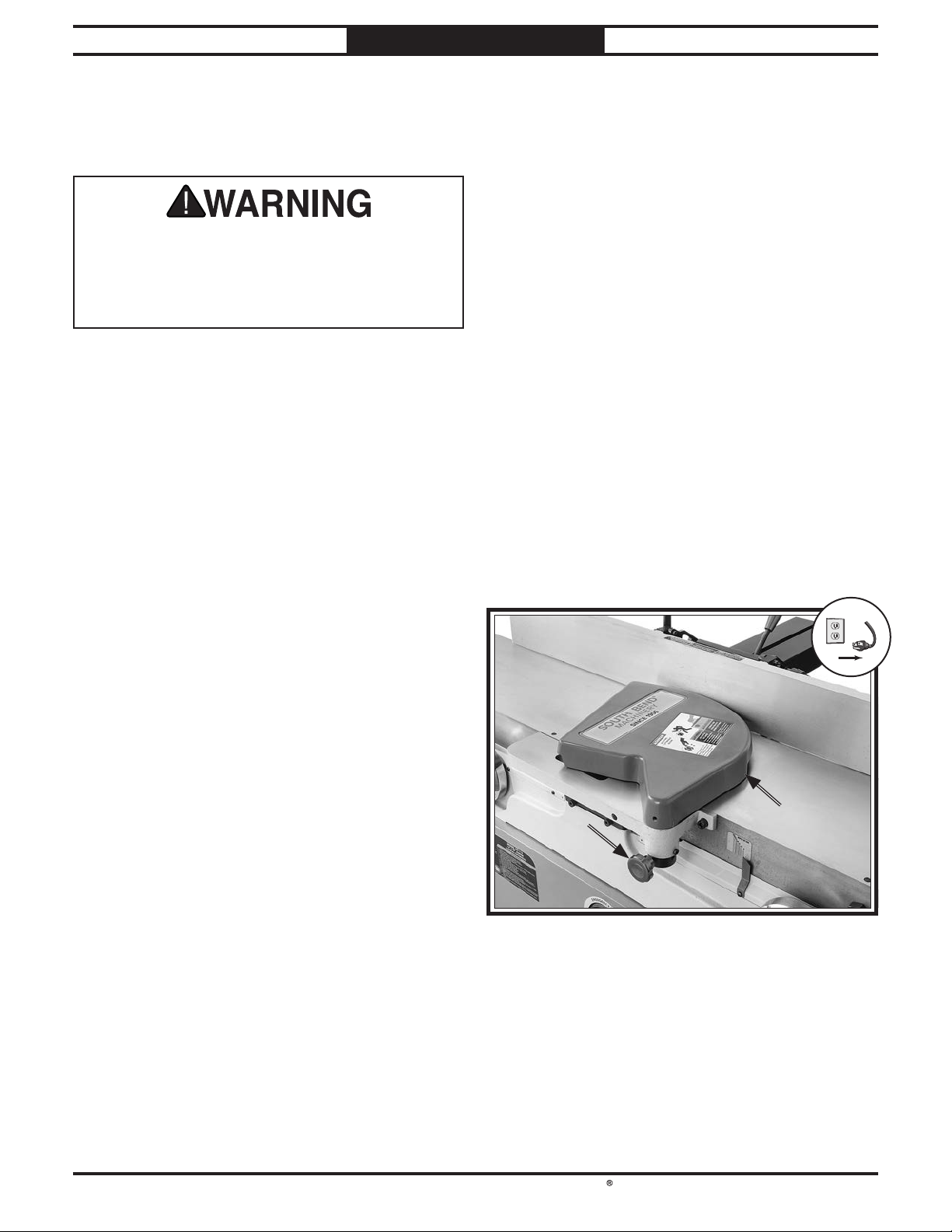
!
South Bend Tools
For Machines Mfd. Since 05/23 Model SB1113
SERVICE
Checking/Adjusting Cutterhead Guard
The cutterhead guard is a critical safety
feature of this jointer. You MUST verify its
operation before using the jointer! Failure to
properly install this guard will greatly increase
risk of serious personal injury.
The cutterhead guard is designed to reduce the
risk of accidental contact with hands or fingers
with the spinning cutterhead. When properly
installed and functioning correctly, the guard
automatically rotates clear of the cutterhead
during the cutting operation and then springs
back over the cutterhead as soon as the operation
is complete.
To check/adjust cutterhead guard for proper
operation:
1. DISCONNECT MACHINE FROM POWER!
2. Set fence to 90° and move it all the way back,
then pull cutterhead guard (see Figure 53)
and let it go.
— If cutterhead guard springs back over
cutterhead, contacts fence, and does
not drag across infeed table, then it is
properly adjusted.
— If cutterhead guard does not spring back
over cutterhead, does contact fence, or
drags across infeed table, then proceed to
Step 3.
Loosen shaft lock (see Figure 53), then
3.
move guard so it is resting against fence, and
1
⁄16" above infeed table.
In order to function as intended, the guard must
be installed as low as possible over the infeed
table without actually touching it (approximately
1
⁄16" above infeed table), and it must have enough
spring tension at the mounting shaft to quickly
reposition itself against the fence after it is
rotated away from the cutterhead and released.
Before performing rabbeting operations, adjust
guard height to just clear outfeed table.
Holding guard height in place, rotate shaft
4.
lock clockwise until knob is centered (see
Figure 53), and tighten to secure setting.
Shaft LockShaft Lock
Figure 53. Cutterhead guard components.
Repeat Step 2 and, if necessary, repeat
5.
Steps 3–4 until cutterhead guard is properly
adjusted.
CutterheadCutterhead
GuardGuard
-41-
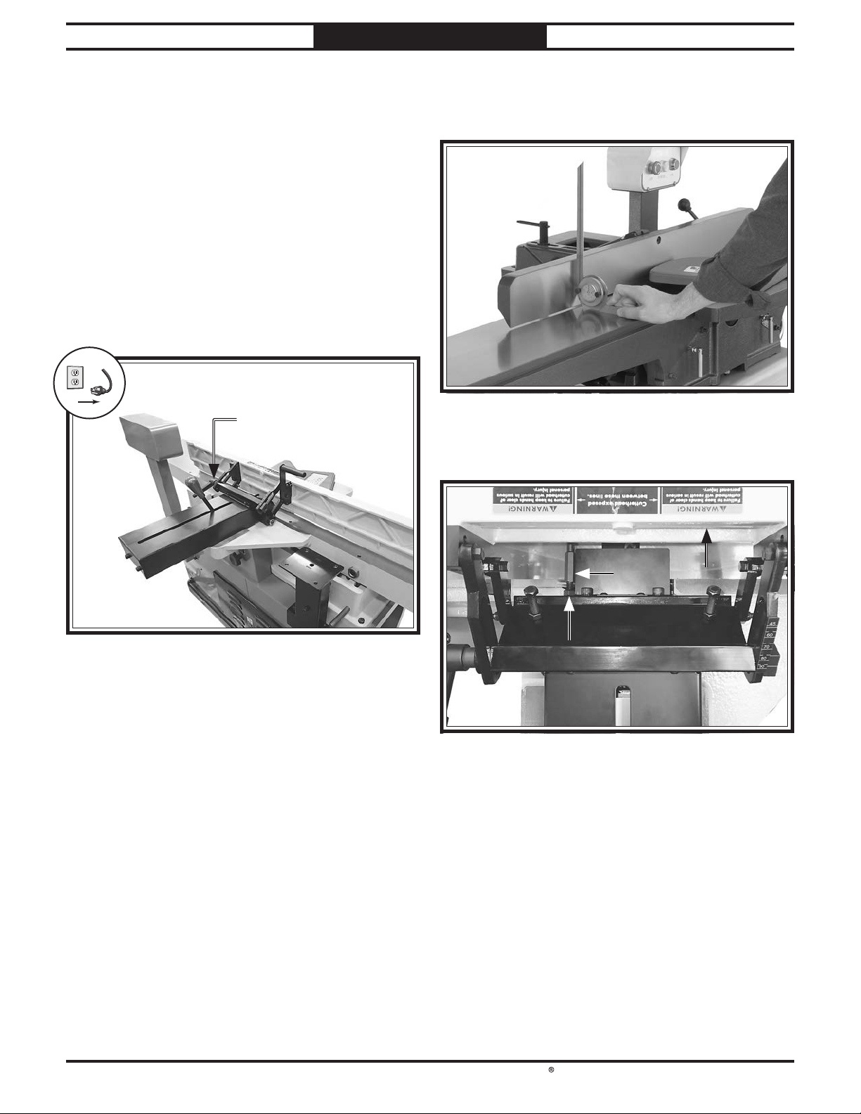
!
South Bend Tools
Model SB1113
SERVICE
Setting Fence Stops
The fence stops simplify the task of adjusting the
fence to 90˚ and 45˚ outward (135˚).
Tools Needed: Qty
Square 90° .............................................................1
Sliding Bevel
Open-End Wrenches 10, 13mm
Setting 90˚ Stop
1. DISCONNECT MACHINE FROM POWER!
2. Loosen fence tilt lock (see Figure 54).
.........................................................1
..................... 1 Ea.
Fence Tilt LockFence Tilt Lock
For Machines Mfd. Since 05/23
3.
Using a 90˚ square, adjust fence to 90˚
position (see Figure 55), then tighten fence
tilt lock.
Figure 55. Example of adjusting fence to 90˚. Example of adjusting fence to 90˚.
4.
Loosen jam nut on 90˚ fence stop (see
Figure 56).
Figure 54. Fence tilt lock location.Fence tilt lock location.
90º Fence90º Fence
StopStop
Jam NutJam Nut
Figure 56. 90˚ fence stop engaged. 90˚ fence stop engaged.
5. Adjust 90˚ fence stop until it makes contact
with fence.
Tighten jam nut loosened in Step 4.
6.
FenceFence
-42-
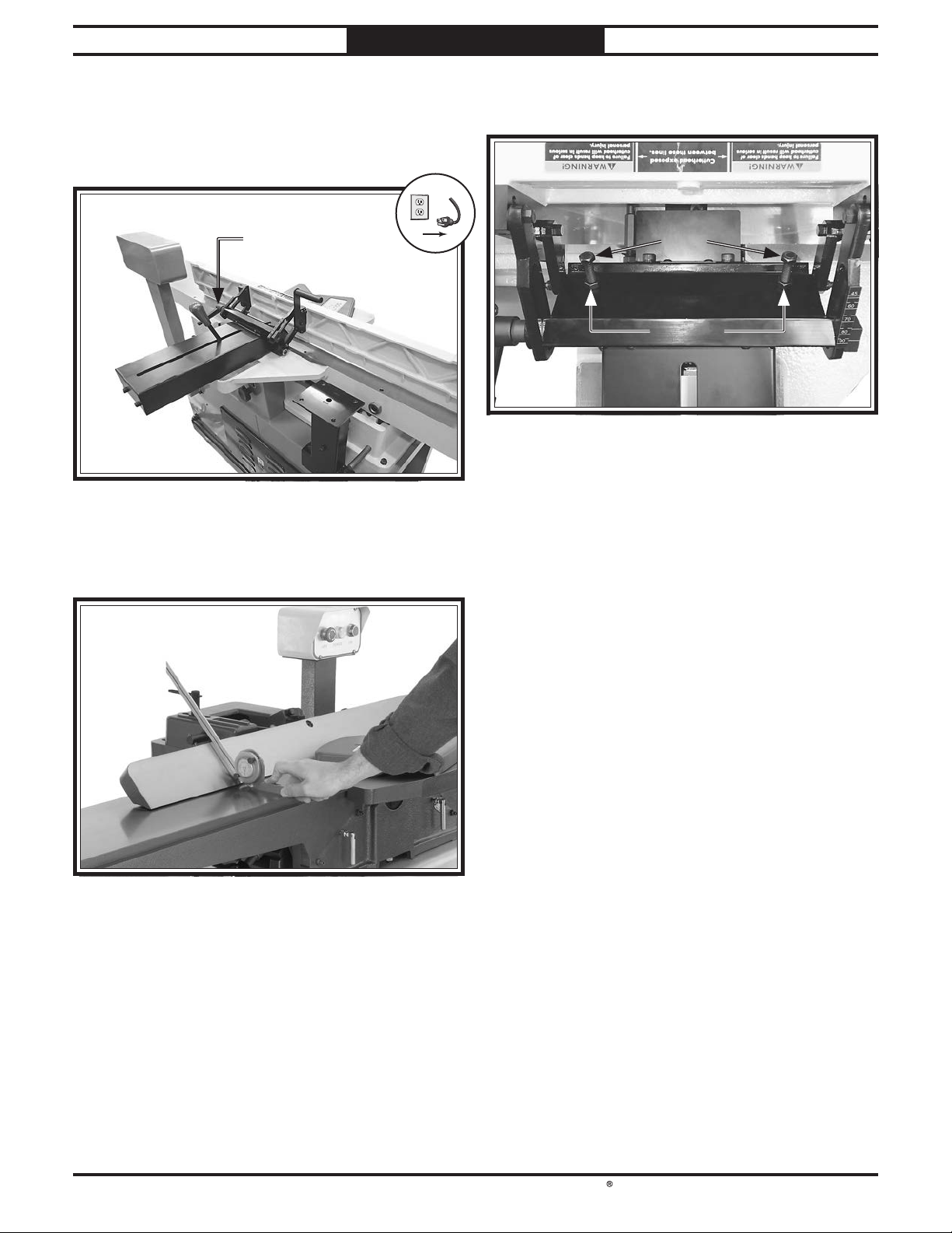
!
South Bend Tools
For Machines Mfd. Since 05/23 Model SB1113
Setting 45˚ Outward (135º) Stop
1. DISCONNECT MACHINE FROM POWER!
2. Loosen fence tilt lock (see Figure 57).
Fence Tilt LockFence Tilt Lock
Figure 57. Fence tilt lock location.Fence tilt lock location.
SERVICE
4.
Loosen jam nuts on 45˚ outward fence stop
bolts (see Figure 59).
Figure 59. 45˚ outward fence stop components. 45˚ outward fence stop components.
5.
Adjust 45˚ outward fence stop bolts until
they make contact with back of fence.
45º Fence Stop 45º Fence Stop
BoltsBolts
Jam NutsJam Nuts
Using a sliding bevel set to 135˚, adjust the
3.
fence to 135˚ (45˚ outward) position (see
Figure 58), then tighten fence tilt lock.
Figure 58. Example of adjusting fence 45˚ outward. Example of adjusting fence 45˚ outward.
Tighten jam nuts loosened in Step 4.
6.
-43-

!
South Bend Tools
Model SB1113
SERVICE
For Machines Mfd. Since 05/23
Replacing/Tensioning V-Belt
To ensure optimum power transmission from the
motor to the cutterhead, the belt must be in good
condition (free from cracks, fraying, and wear)
and properly tensioned.
Item(s) Needed: Qty
Replacement V-Belt (PSB1113172) ......................1
Open-End Wrench 17/19mm
Phillips Head Screwdriver #2
Replacing V-Belt
1. DISCONNECT MACHINE FROM POWER!
2. Remove rear access panel and belt guard.
3. Loosen adjustment nuts on tension rod (see
Figure 60) to allow motor to raise or lower.
................................1
...............................1
Tensioning V-Belt
1. DISCONNECT MACHINE FROM POWER!
2. Perform Steps 2–3 in Replacing V-Belt.
3. Lower motor and adjust belt tension with
tension rod adjustment nuts so there is
approximately
pushed with moderate pressure, as shown in
Figure 61.
Rotate adjustment nuts clockwise to allow
—
motor to drop and apply tension to belt.
Rotate adjustment nuts counterclockwise
—
to raise motor and release belt tension.
1
/2" deflection when belt is
Pulley
Tension RodTension Rod
(1 of 2)(1 of 2)
Adjustment Adjustment
NutsNuts
(2 of 4)(2 of 4)
Figure 60. V-belt tension adjustment components.
4.
Lift motor up, slide belt off motor and
cutterhead pulleys, and replace with a new
one.
5. Proceed to Step 3 of Tensioning V-Belt.
½" Deflection
Pulley
Figure 61. Checking V-belt tension.Checking V-belt tension.
4.
Replace rear access panel and belt guard
removed in Step 2 of Replacing V-Belt.
-44-

!
South Bend Tools
For Machines Mfd. Since 05/23 Model SB1113
SERVICE
Pulley Alignment
Pulley alignment is another important factor in
power transmission and belt life. The pulleys
should be parallel to each other and in the same
plane (coplaner) for optimum performance.
The motor pulley can be adjusted by loosening
the motor mount adjustment nuts, sliding the
motor in or out, and retightening the adjustment
nuts to lock the motor in place.
Tools Needed: Qty
Straightedge 48" ...................................................1
Open-End Wrench 17/19mm
Phillips Head Screwdriver #2
................................1
...............................1
To align pulleys:
1. DISCONNECT MACHINE FROM POWER!
2. Remove rear access cover, V-belt guard, and
fence assembly.
Place a straightedge against both pulleys
3.
(see Figure 62) and check to make sure they
are aligned and that V-belt is straight up
and down (see Figure 63).
Cutterhead
Pulley
Alignment
Motor
Pulley
Figure 63. Example of V-belt aligned with pulleys. Example of V-belt aligned with pulleys.
— If pulleys are aligned, go to Step 7.
— If pulleys are NOT aligned, perform
Steps 4–7.
Loosen motor mount adjustment nuts shown
4.
in Figure 64.
Adjustment Nuts Adjustment Nuts
(2 of 4)(2 of 4)
StraightedgeStraightedge
Figure 62. Example of checking belt alignment. Example of checking belt alignment.
Figure 64. Motor mount adjustment nuts.Motor mount adjustment nuts.
Shift motor horizontally as needed to align
5.
motor pulley with cutterhead pulley.
Tighten motor mount adjustment nuts.
6.
V-belt should be parallel and aligned as
shown in Figure 63.
Re-install fence assembly, rear access panel,
7.
and V-belt guard.
-45-

South Bend Tools
Model SB1113
TROUBLESHOOTING
For Machines Mfd. Since 05/23
If you need replacement parts, or if you are unsure how to do any of the solutions given here, feel free
to call us at (360) 734-1540.
Symptom Possible Cause Possible Solution
Machine does not
start, or power
supply breaker
trips immediately
after startup.
Machine stalls or is
underpowered.
1.
Emergency Stop button depressed/
at fault.
2.
Knee Stop button is engaged/at
fault.
3.
Incorrect power supply voltage or
circuit size.
4.
Power supply circuit breaker
tripped or fuse blown.
5.
Motor wires connected incorrectly.
6.
Thermal overload relay has tripped/
at fault.
7.
Start capacitor is at fault.
8.
Centrifugal switch adjustment/
contact points at fault.
9.
Contactor not energized/at fault.
10.
Wiring broken, disconnected, or
corroded.
11.
START switch at fault.
12.
Motor or motor bearings at fault.
1.
Workpiece material unsuitable for
machine.
2.
Feed rate/cutting speed too fast.
3.
Excessive depth of cut.
4.
Dust collection ducting problem.
5.
Machine undersized for task.
6.
Inserts dull or wrong inserts
installed.
7.
Belt(s) slipping/pulleys misaligned.
8.
Motor wired incorrectly.
9.
Pulley/sprocket slipping on shaft.
10.
Motor overheated.
11.
Run capacitor at fault.
12.
Extension cord too long.
13.
Contactor not energized/at fault.
14.
Centrifugal switch/contact points
at fault.
15.
Motor or motor bearings at fault.
1.
Rotate Emergency Stop Button head to reset.
Replace if at fault.
2.
Cycle machine power/replace knee stop button if at
fault.
3.
Ensure correct power supply voltage and circuit
size.
4.
Ensure circuit is free of shorts. Reset circuit breaker
or replace fuse.
5.
Correct motor wiring connections (Page 50).
6.
Reset. Adjust or replace if at fault.
7.
Test/replace if at fault.
8.
Adjust centrifugal switch/clean contact points.
Replace either if at fault.
9.
Test all legs for power; replace if necessary.
10.
Fix broken wires or disconnected/corroded
connections (Page 50).
11.
Replace switch.
12.
Replace motor.
1.
Only cut wood/ensure moisture content is below
20% (Page 23).
2.
Decrease feed rate/cutting speed.
3.
Decrease depth of cut (Page 29).
4.
Clear blockages, seal leaks, use smooth wall duct,
eliminate bends, close other branches.
5.
Use correct/sharp inserts (Page 38). Reduce feed
rate or depth of cut (Page 29).
6.
Use correct/sharp inserts (Page 38).
7.
Clean/tension/replace belt(s); ensure pulleys are
aligned (Page 45).
8.
Wire motor correctly.
9.
Tighten/replace loose pulley/shaft.
10.
Clean motor, let cool, and reduce workload.
11.
Test/repair/replace.
12.
Move machine closer to power supply; use shorter
extension cord.
13.
Test all legs for power; repair/replace if at fault.
14.
Adjust centrifugal switch/clean contact points.
Replace either if at fault.
15.
Replace motor.
-46-

South Bend Tools
For Machines Mfd. Since 05/23 Model SB1113
TROUBLESHOOTING
Symptom Possible Cause Possible Solution
Machine has
vibration or noisy
operation.
Table is hard to
adjust.
Excessive snipe
(gouge in end
of board that
is uneven with
rest of cut); back
of workpiece is
concave.
1.
Motor or component is loose.
2.
Stand feet not adjusted properly.
3.
V-belt(s) worn, loose, pulleys
misaligned or belt slapping cover.
4.
Insert(s) are at fault.
5.
Pulley loose.
6.
Motor mount loose/broken.
7.
Motor fan rubbing on fan cover.
8.
Cutterhead bearings at fault.
9.
Centrifugal switch.
10.
Motor bearings at fault.
1.
Table lock engaged/partially
engaged.
2.
Table stop blocking movement.
1.
Outfeed table set too low.
2.
Operator pushing down on trailing
end (infeed side) of workpiece as it
leaves cutterhead.
1.
Replace damaged or missing bolts/nuts or tighten if
loose.
2.
Adjust stand feet to stabilize machine.
3.
Inspect/replace belts with a new matched set.
Realign pulleys if necessary (Page 44).
4.
Replace/rotate insert(s) (Page 38).
5.
Secure pulley on shaft.
6.
Tighten/replace.
7.
Fix/replace fan cover; replace loose/damaged fan.
8.
Replace bearing(s)/realign cutterhead.
9.
Replace.
10.
Test by rotating shaft; rotational grinding/loose
shaft requires bearing replacement.
1.
Completely loosen table lock.
2.
Loosen/reset table positive stop (Page 39).
1.
Align outfeed table with cutterhead inserts at top
dead center (Page 40).
2.
Focus most of the workpiece pressure against
outfeed table while cutting.
Workpiece stops in
middle of cut; front
of workpiece is
concave.
Workpiece
chipping, tear-out,
indentations, or
overall rough cuts.
1.
Outfeed table set too high.
1.
Workpiece rough or has loose knots/
surface flaws; not suitable for
jointing.
2.
Not feeding workpiece to cut "with"
the grain.
3.
Dull/nicked/chipped insert(s).
4.
Feeding workpiece too fast.
5.
Excessive depth of cut.
6.
Lack of proper dust collection or
clogged dust port.
1.
Align outfeed table with cutterhead inserts at top
dead center (Page 40).
1.
Inspect workpiece (Page 23). Use smooth stock
without loose knots/surface flaws.
2.
Flip workpiece 180° before feeding again.
3.
Rotate/replace insert(s) (Page 38).
4.
Reduce feed rate.
5.
Reduce depth of cut (Page 29).
6.
Clear blockages, ensure dust collection is operating
efficiently; upgrade dust collector.
-47-

South Bend Tools
Model SB1113
TROUBLESHOOTING
For Machines Mfd. Since 05/23
Symptom Possible Cause Possible Solution
Fuzzy grain left in
workpiece.
Long lines or ridges
that run along the
length of the board.
Uneven cutter
marks, wavy
surface, or chatter
marks across face
of workpiece.
Glossy surface;
scorching or
burn marks on
workpiece.
Workpiece is
concave or convex
along its length
after jointing.
1.
Wood has high moisture content.
2.
Dull insert(s).
1.
Nicked or chipped insert(s).
Loose or incorrectly installed
insert(s).
Dirt or debris under carbide
insert(s).
1.
Feeding workpiece too fast.
2.
Insert(s) not adjusted at even
heights in cutterhead.
1.
Dull insert(s).
2.
Feed rate too slow.
1.
Workpiece not held with even
pressure against outfeed table
during cut.
2.
Workpiece too uneven at start of
operation.
3.
Tables not parallel with cutterhead
and each other.
1.
Ensure wood moisture content is less than 20%.
Allow to dry if necessary.
2.
Replace/rotate insert(s) (Page 38).
1.
Replace/rotate insert(s) (Page 38).
Remove/replace insert(s) and re-install
(Page 38).
Remove insert(s), clean bottom of insert/cutterhead
mounting pocket and re-install (Page 38).
1.
Reduce feed rate.
2.
Remove, clean, and re-install any inserts that are
"raised" in cutterhead (Page 38).
1.
Replace/rotate insert(s) (Page 38).
2.
Increase feed rate.
1.
Apply even downward pressure against workpiece
throughout entire travel along outfeed side during
cut.
2.
Take partial cuts to remove extreme high spots
before doing a full pass.
3.
Check/adjust table parallelism (Page 35).
Workpiece edges
not square; tapered
cut produced.
1.
Fence not square to table(s); fence
tilt unlocked.
2.
Warped infeed or outfeed table.
3.
Insert(s) not at even heights.
1.
Square fence to table(s); lock fence.
2.
Regrind/replace table.
3.
Remove, clean, and re-install any insert(s) any
inserts that are "raised" in cutterhead (Page 38).
-48-

South Bend Tools
For Machines Mfd. Since 05/23 Model SB1113
Shock Hazard: It is extremely dangerous to
Wire Connections:
Modifications:
Motor Wiring:
junction box.
Circuit Requirements: Connecting the machine
power inverters store an electrical charge for
our Technical Support at (360) 734-1540.
ELECTRICAL
Electrical Safety Instructions
These pages are accurate at the time of printing. In the constant effort to improve, however, we may
make changes to the electrical systems of future machines. Study this section carefully. If you see
differences between your machine and what is shown in this section, call Technical Support at (360)
734-1540 for assistance BEFORE making any changes to the wiring on your machine.
perform electrical or wiring tasks while the
machine is connected to the power source.
Touching electrified parts will result in
personal injury including but not limited to
severe burns, electrocution, or death. For
your own safety, disconnect machine from
the power source before servicing electrical
components or performing any wiring tasks!
All connections must be
tight to prevent wires from loosening during
machine operation. Double-check all wires
disconnected or connected during any wiring
task to ensure tight connections.
Using aftermarket parts or
modifying the wiring beyond what is shown
in the diagram may lead to unpredictable
results, including serious injury or fire.
The motor wiring shown in these
diagrams is current at the time of printing,
but it may not match your machine. Always
use the wiring diagram inside the motor
to an improperly sized circuit will greatly
increase the risk of fire. To minimize
this risk, only connect the machine to a
power circuit that meets the minimum
requirements given in this manual.
Capacitors/Inverters: Some capacitors and
up to 10 minutes after being disconnected
from the power source. To reduce the risk of
being shocked, wait at least this long before
working on capacitors.
Wire/Component Damage: Damaged wires
or components increase the risk of serious
personal injury, fire, or machine damage. If
you notice that any wires or components are
damaged while performing a wiring task,
replace those wires or components before
completing the task.
Experiencing Difficulties: If you are
experiencing difficulties understanding the
information included in this section, contact
BLACK
BLUE
BROWN
NOTICE:
WIRING DIAGRAM COLOR KEY
BLUE
WHITE
GREEN
G R AY
The photos and diagrams included in this section are best viewed in color. You can
see them in color at www.southbendtools.com.
RED
LIGHT
BLUE
ORANGE
PINK
PURPLE
TURQUIOSE
WHITE
YEL LOW
GREEN
YEL LOW
-49-

South Bend Tools
Model SB1113
Wiring Diagram
CONTROL PANEL
ELECTRICAL
For Machines Mfd. Since 05/23
Ground
X1 X2
POWER
K
E
-
2
2
2
D
S
M
M
2
A
R/ 1/L1
U/2 /T1 W/6/T3
1/2
NC
EMERGENCY
STOP
R
E
N
S/3/L2
SDE
MA-30
V/4/T2
3/4
NO C
Y
2
2
T/5/ L3
NO
13
M
M
YK A600 22MM
21
START
NC
14
DIGITAL
READOUT
22
WR5502CT
(2 AA A Batteries)
DRO
SENSOR
WR 55 01
KNEE STOP
BUTTON
5/6
NC 21
NO 13
NO 14
NC22
RA-30
B
Ground
AMP
RESET
OFF
18
26
22
98
96
95
NC
COM
250VAC
400MFD
Start Capacitor
Run Capacitor
35uF 450VAC
MOTOR
230V
-50-
MAGNETIC SWITCH MPE-30
Ground
MOTOR JUNCTION BOX
Ground
Hot
Hot
X
G
Y
230 VAC
L6-30 PLUG

South Bend Tools
For Machines Mfd. Since 05/23 Model SB1113
ELECTRICAL
Electrical Components
Figure 65. Control panel overview. Control panel overview.
Figure 66. Magnetic switch cover. Magnetic switch cover. Figure 67. Magnetic switch wiring. Magnetic switch wiring.
-51-
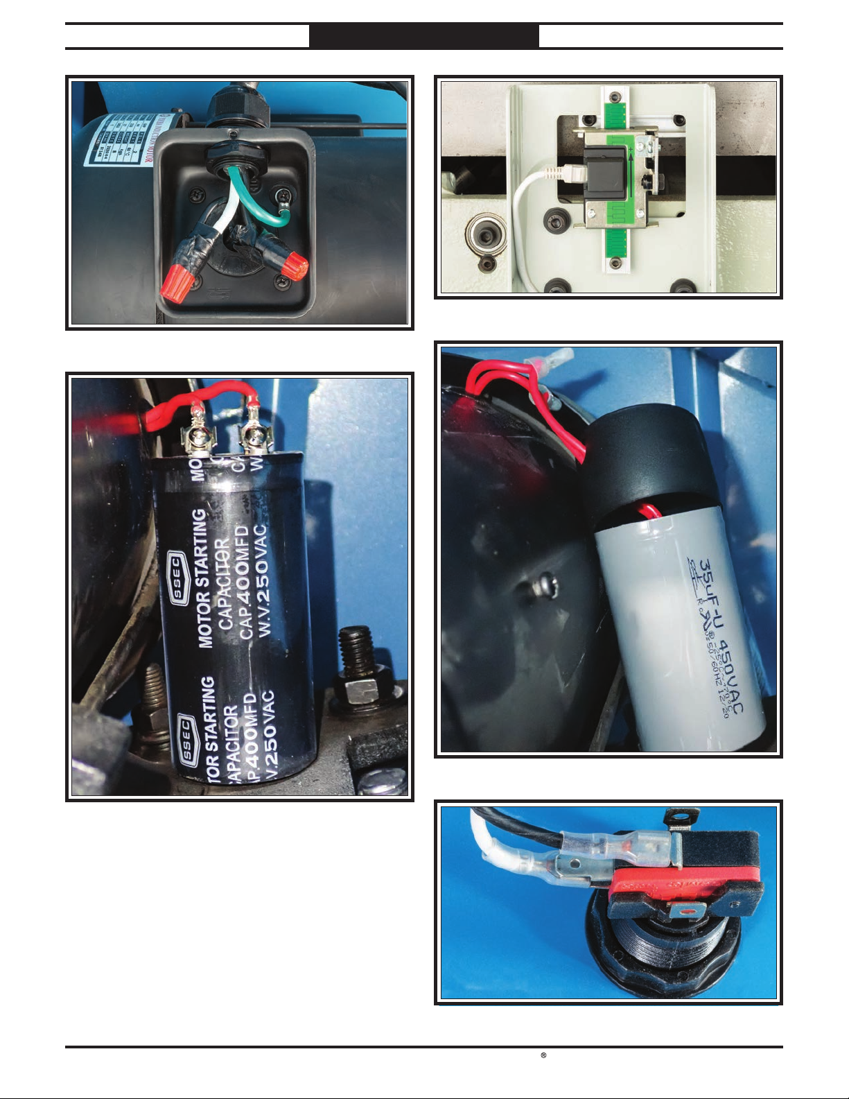
South Bend Tools
Model SB1113
Figure 68. Motor junction box wiring. Motor junction box wiring.
ELECTRICAL
For Machines Mfd. Since 05/23
Figure 70. DRO Sensor WR5501. DRO Sensor WR5501.
Figure 69. Start Capacitor 400MFD 250VAC. Start Capacitor 400MFD 250VAC.
-52-
Figure 71. Run Capacitor 35μF 450VAC. Run Capacitor 35μF 450VAC.
Figure 72. Knee Stop Button 100mm. Knee Stop Button 100mm.

C1
3
30
33
South Bend Tools
For Machines Mfd. Since 05/23 Model SB1113
PARTS
Fence
35
19
36
49
C2
31
C2
9
9
32
5
6
45
40V2
41
23
19
18
A
34
9
43
9
7
11
21
28V2
33
8
9
10
20
4
B
26
41
42
34
212V2
36
37
9
37
36
43
C1
42
34
33
32
44
34
41
38
46
45
39
22
192
41
38
2
47
218
4
4
2
1
A
12
13
15
14
16
17
29
-53-

REF PART # DE SCR IPTION REF PART # DE SCR IPTION
South Bend Tools
Model SB1113
PARTS
For Machines Mfd. Since 05/23
Fence Parts List
1 PSB1113001 CAP SCREW M8-1.25 X 16 28 V2 PSB1113028V2 LOCKING COLLAR V2.05.23
2 PSB1113002 LOCK WASHER 8MM 29 PSB1113029 LEVER HANDLE 1/2-13 X 7/8, 10-1/4
3 PSB1113003 FENCE PISTON COVER 30 PSB1113030 FIX ED H AN DLE 18 X 90 , M8-1.2 5
4 PSB1113004 BUTTON HD CAP SCR M5-.8 X 8 31 PSB1113031 FENCE TILT HANDLE BRACKET
5 PSB1113005 KNOB 3/8-16, D36, TAPERED 32 PSB1113032 BUTTON HD CAP SCR M8-1.25 X 20
6 PSB1113006 STUD-UDE M6-1 X 110, 12, 3/8-16 X 15 33 PSB1113033 CAP SCREW M6-1 X 35
7 PSB1113007 FENCE HANDLE SHAFT 34 PSB1113034 FLAT WASHER 6.8 X 14 X 0.3MM
8 PSB1113008 ROLL PIN 5 X 25 35 PSB1113035 CAP SCREW M6-1 X 25
9 PSB1113009 LOC K N UT M6-1 36 PSB1113036 FLAT WASHER 6MM
10 PSB1113010 DOWEL PIN 10 X 20 BR 37 PSB1113037 FEN CE TILT HA NDLE SUPPORT BLOCK
11 PSB1113011 PISTON SUPPORT PLA TE 38 PSB1113038 FLAT WASHER 8MM
12 PSB1113012 FEN CE PISTON 39 PSB1113039 BA LL BEARING 608 ZZ
13 PSB1113013 CAP SCREW M4-.7 X 8 40V2 PSB1113040V2 FEN CE SUPPORT BRA CKET V2.05.23
14 PSB1113014 ROLL PIN 4 X 16 41 PSB1113041 HEX BOLT M10-1.5 X 30
15 PSB1113015 FEN CE HANDLE SHAFT BRACKET 42 PSB1113042 STANDOFF-ROUND MM M6-1
16 PSB1113016 LOCK WASHER 5MM 43 PSB1113043 F EN CE TILT SUPPORT BRACKET
17 PSB1113017 CAP SCREW M5-.8 X 10 44 PSB1113044 HEX BOLT M8-1.25 X 40
18 PSB1113018 CAP SCREW M6-1 X 20 45 PSB1113045 HEX NUT M8-1.25
19 PSB1113019 LOCK WASHER 6MM 46 PSB1113046 FEN CE SUPPORT GUARD PLATE
20 PSB1113020 FLAT WASHER 5MM 47 PSB1113047 CAP SCREW M8-1.25 X 30
21 PSB1113021 FENCE PISTON SUPPORT 49 PSB1113049 FENCE
22 PSB1113022 T-SLOT NUT 1/2", 1 /2-13 1 92 PSB1113192 FEN CE ANGLE SCALE
23 PSB1113023 TILT SLIDE BLOCK 212V2 PSB1113212V2 TILT SLIDE B LOCK V2.05.23
24 PSB1113024 HEX N UT M5-.8 218 PSB1113218 STANDOFF-HEX MALE M8-1.25 X 28, 90
26 PSB1113026 LINEA R BEARING LM20UU
-54-

71
135
South Bend Tools
For Machines Mfd. Since 05/23 Model SB1113
PARTS
Base
109
136
137
147
112
111
114V2
D
133
127
134
127
24
138
146
I
97
94
151
139
98
45
90
9
150
115
116
99
89
113
102
140
127
F
100
101
C
104
52
51
93
92
91
88
87
91
118
123
92
87
93
122
88
120
121
89
94
123
117
105
98
122
99
90
119
121
143
141
144
101
45
126
118
148
104
I
52
51
106
105
128
127
117
130
129
101
E
100
103
102
45
97
124
4
120
105
4
125
119
141
142
145
146
147
F
149
107
110
109
108
C
132
131
209
C
D
-55-

REF PART # DE SCR IPTION REF PART # DE SCR IPTION
South Bend Tools
Model SB1113
PARTS
Base Parts List
4 PSB1113004 BUTTON HD CAP SC R M5-.8 X 8 118 PSB1113118 EXT RETAIN IN G RING 17MM
9 PSB1113009 LOCK N UT M6-1 119 PSB1113119 HANDWHEEL SHAFT
24 PSB1113024 HEX N UT M5-.8 120 PSB1113120 KEY 5 X 5 X 10
45 PSB1113045 HEX N UT M8 -1.25 121 PSB1113121 B USH ING 15ID X 32 OD X 7L
51 PSB1113051 FLAT WASHER 10MM 122 PSB1113122 HANDWHEEL TYPE-13 160D X 12B-K X M6-1
52 PSB1113052 LOCK WASHER 10MM 123 PSB1113123 KNOB 5/16-18, D46, 6-LOBE
71 PSB1113071 TA P S CREW M5 X 8 124 PSB1113124 TABLE GUARD (LEFT)
87 PSB1113087 CAP SCREW 10-24 X 1/2 125 PSB1113125 TABLE GUARD (RIGHT)
88 PSB1113088 BALL BEARING 6000ZZ 126 PSB1113126 B UTTON HD CAP SCR M5-.8 X 1 0
89 PSB1113089 BEARING COVER 127 PSB1113127 FLAT WASHER 5MM
90 PSB1113090 PINION GEAR 128 PSB1113128 DEPTH SCALE POINTER
91 PSB1113091 FEN DER WASHER 5MM 129 PSB1113129 KNOB 1/4-20, D25, BALL
92 PSB1113092 B UTTON HD CAP SCR M5-.8 X 16 130 PSB1113130 S TUD-DE 1/ 4-20 X 50, 1 2
93 PSB1113093 ROLL PIN 4 X 25 131 PSB1113131 LOCK NUT 1/4-20
94 PSB1113094 BASE SHAFT 132 PSB1113132 FLAN GE SCREW M5-.8 X 6
97 PSB1113097 CAP SCREW M6-1 X 15 133 PSB1113133 CAP SCREW M5-.8 X 20
98 PSB1113098 LOCK NUT M8-1.25 134 PSB1113134 COMPRESSION SPRING 0.6 X 7.6 X 10.4
99 PSB1113099 STRUT BRA CKET 1 35 PSB1113135 HEX B OLT M6-1 X 12
100 PSB1113100 TAB LE STRUT 136 PSB1113136 BEARING BRACKET
101 PSB1113101 CAP SCREW M8-1.25 X 20 137 PSB1113137 LOC K N UT M3-.5
102 PSB1113102 HEX BOLT M8-1.25 X 50 138 PSB1113138 ANGLE BRACKET
103 PSB1113103 HEX BOLT M8-1.25 X 30 139 PSB1113139 PHLP HD SCR M5-.8 X 6
104 PSB1113104 HEX BOLT M10-1.5 X 45 140 PSB1113140 DRO S EN SOR COVER
105 PSB1113105 BA LL BEARING 600 2Z Z 141 PSB1113141 FLAT WASHER 3MM
106 PSB1113106 FLAT WASHER 8MM 142 PSB1113142 BUSHIN G 3ID x 6OD x 6L
107 PSB1113107 CAP SCREW M8-1.25 X 20 143 PSB1113143 BALL B EARING 606 ZZ
108 PSB1113108 STANDOFF-HEX MF M10-1.5 X 10, M8-1.25 144 PSB1113144 PHLP HD SCR M3-.5 X 15
109 PSB1113109 FLAT WASHER 6MM 1 45 PSB1113145 DIGITAL SEN SOR WR5501
110 PSB1113110 B UTTON HD CAP SCR M6-1 X 1 0 146 PSB1113146 FEN DER WASHER 5MM
111 PSB1113111 STANDOFF-HEX MM M10-1.5 X 98, 10 147 PSB1113147 FLAT WASHER 5MM
112 PSB1113112 V-B ELT C OVER 148 PSB1113148 FLAT WASHER 8MM
113 PSB1113113 KNOB M10-1.5, 6-LOBE, D62 149 PSB1113149 DRO SENSOR B RACKET
114V2 PSB1113114V2 TABLE BASE V2.05.22 150 PSB1113150 CAP SCREW M5-.8 X 12
115 PSB1113115 PHLP HD SCR M3-.5 X 12 151 PSB1113151 MAGNETIC SCALE
116 PSB1113116 N YLON CLAMP TIE ALC-110S 209 PSB1113209 POS ITION PLATE
117 PSB1113117 LIFTING BAR
For Machines Mfd. Since 05/23
-56-
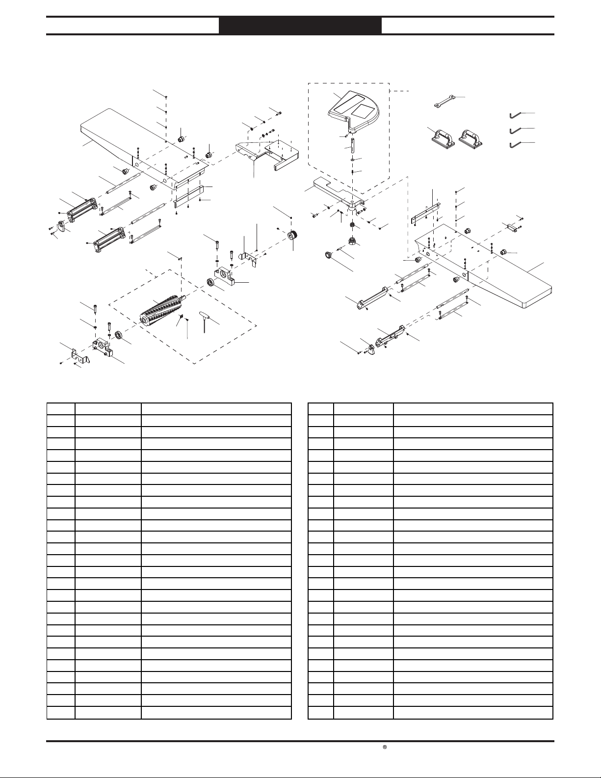
4
72
REF PAR T # DESCRIPT ION REF PAR T # DE SCR IPTION
South Bend Tools
For Machines Mfd. Since 05/23 Model SB1113
PARTS
Table & Accessories
82
54
84
81
85
86
55
52
78
79
75
80
56
58
57
73
74
32
58-1
59
58-3
75
58-2
55
75
70
71
51
57
58-4
54
52
50
4
56
53
60
B
61
63
53
62-1
62-2
52
64
62-3
65
79
84
83
68
69
62-4
62-5
66
67
82
65
78
64
75
81
62
197
81
70
80
32
243
240
241
242
72
73
32
76
18
75
77
74
71
80
4 PSB1113004 BUTTON HD CA P S CR M5-.8 X 8 65 PSB1113065 SET S CREW 1/4-20 X 3/4
18 PSB1113018 CAP SCREW M6-1 X 20 66 PSB1113066 TORSION SPRING 2.6 X 30 X 47.5
32 PSB1113032 BUTTON HD CAP SCR M8-1.25 X 20 67 PSB1113067 B US HING 19ID X 50 OD X 44L
50 PSB1113050 FENCE B RACKET 68 PSB1113068 SET SCREW M8 -1.25 X 40
51 PSB1113051 FLAT WASHER 10MM 69 PSB1113069 KNOB M8-1.25, 6-LOBE, D50
52 PSB1113052 LOCK WASHER 10MM 70 PSB1113070 CHIP BREAKER
53 PSB1113053 CAP SCREW M10-1.5 X 30 71 PSB1113071 TAP S CREW M5 X 8
54 PSB1113054 CUTTERH EAD BEA RIN G COVER 72 PSB1113072 SCREW COVER
55 PSB1113055 CAP SCREW M10 -1.5 X 50 73 PSB1113073 SET SCREW M8-1 .25 X 10
56 PSB1113056 B EARIN G SUPPORT BLOCK 74 PSB1113074 B US H ING 6ID x 8OD x 8 L
57 PSB1113057 BALL BEA RIN G 6205-2NSE 75 PSB1113075 ECCENTRIC BUSHING
58 PSB1113058 HELICAL CUTTERHEAD ASSEMBLY 76 PSB1113076 SENSOR MOUNT B LOCK
58-1 PSB1113058-1 HELICAL CUTTERHEAD 12" 77 PSB1113077 IN FEED TABLE
58-2 PSB1113058-2 FLAT H D TORX SCR 10 -32 X 1/2 78 PSB1113078 TILT SH AFT
58-3 PSB1113058-3 INSERT 15 X 15 X 2.5MM 79 PSB1113079 TILT B RACKET
58-4 PSB1113058-4 T-HA NDLE TORX DRIVER T-25 80 PSB1113080 TILT B RACKET MOUNT
59 PSB1113059 KEY 6 X 6 X 30 RE 81 PSB1113081 SET SCREW M8-1 .25 X 10
60 PSB1113060 SET SCREW M8-1.25 X 20 82 PSB1113082 POSITIVE STOP B RACKET
61 PSB1113061 CUTTERHEAD PULLEY 83 PSB1113083 ELEVATION BRACKET (RIGHT)
62 PSB1113062 CUTTERHEAD GUARD AS SEMB LY 84 PSB1113084 CAP SCREW M6-1 X 12
62-1 PSB1113062-1 CUTTERHEAD GUARD COVER 85 PSB1113085 OUTFEED TAB LE
62-2 PSB1113062-2 SET SCREW M8-1.25 X 20 86 PSB1113086 ELEVATION BRACKET (LEFT)
62-3 PSB1113062-3 CUTTERHEA D GUARD SHAF T 197 PSB1113197 SAFETY PUSH BLOCK
62-4 PSB1113062-4 FEN DER WASHER 6MM 240 PSB1113240 HEX WRENCH 5MM
62-5 PSB1113062-5 CAP SCREW M6-1 X 15 241 PSB1113241 HEX WRENCH 6MM
63 PSB1113063 RA BBETING TAB LE 242 PSB1113242 HEX WRENCH 8MM
64 PSB1113064 HEX NUT 1/4-20 243 PSB1113243 WRENCH 17 X 19MM OPEN-ENDS
-57-

176
71
South Bend Tools
Model SB1113
Stand & Motor
PARTS
For Machines Mfd. Since 05/23
174
175
177
51
175
174
60
173
179
181
182
183
110
60
171-14
171
178
60
51
52
180
171-16
171-15
60
177
184
171-10
179
106
183
187
2
171-1
171-3
171-7
185
182
171-13
171-12
171-9
181
171-2
171-4
171-11
171-6
171-8
171-5
172
158
157
4
188
156
155
154
170
153
162
161-1
160
161-2
163
164V2
127
165
167
159
J
152
161
168
169
127
165
166
2
106
191
106
193
186
2
190-1V2
G
167
H
190-2
187
189
195
196-5
J
196-11
196-10
196
190V2
106
2
193
196-7
196-9
196-1
196-2
196-3
196-4
196-7
196-8
G
196-6
196-3
H
-58-
194

REF PAR T # DESCR IPT ION REF PART # DE SCRIPT ION
South Bend Tools
For Machines Mfd. Since 05/23 Model SB1113
PARTS
Stand & Motor Parts List
2 PSB1113002 LOCK WASHER 8MM 171-12 PSB1113171-12 WIRE NUT SW-P 4
4 PSB1113004 BUTTON HD CA P S CR M5-.8 X 8 171-13 PSB1113171-13 STRA IN RELIEF TYPE-3 M25-1.5
51 PSB1113051 FLAT WASHER 10MM 171-14 PSB1113171-14 KEY 6 X 6 X 40 RE
52 PSB1113052 LOCK WASHER 10MM 171-15 PSB1113171-15 M OTOR P ULLEY
60 PSB1113060 SET SCREW M8-1.25 X 20 171-16 PSB1113171-16 SET SCREW M8-1.25 X 25
71 PSB1113071 TA P SCREW M5 X 8 172 PSB1113172 V-B ELT 480-J9
106 PSB1113106 FLAT WASHER 8MM 173 PSB1113173 HEX NUT M10-1.5
109 PSB1113109 FLAT WASHER 6MM 174 PSB1113174 FLAT WASHER 13MM
110 PSB1113110 B UTTON HD CAP SCR M6-1 X 10 175 PSB1113175 HEX NUT M12-1.75
127 PSB1113127 FLAT WASHER 5MM 176 PSB1113176 ADJUSTMENT ROD
152 PSB1113152 CONTROL PAN EL HOUSIN G 177 PSB1113177 PLATE CONN ECTING ROD
153 PSB1113153 DRO CORD 1 8G 1W 6" 1 78 PSB1113178 MOTOR PLATE
154 PSB1113154 BUTTON SWITCH YK A600 22MM GREEN 179 PSB1113179 CONNECTIN G ROD COLLAR
155 PSB1113155 E-STOP BUTTON REN Y 22MM 250 V 180 PSB1113180 CAP SCREW M10-1.5 X 40
156 PSB1113156 POWER LIGHT KE-22DS 22MM 230V 181 PSB1113181 HEX BOLT M12-1.75 X 30
157 PSB1113157 CONTROL PANEL FACEPLATE 182 PSB1113182 LOCK WASHER 12MM
158 PSB1113158 BUTTON HD CAP SCR M4-.7 X 6 183 PSB1113183 FLAT WASHER 12MM
159 PSB1113159 TA P S CREW M 3 X 8 184 PSB1113184 ACCESSORY COLUMN
160 PSB1113160 DRO MOUNTING B RAC KET 185 PSB1113185 CAP SCREW M8-1.25 X 70
161 PSB1113161 DIGITA L READOUT ASS EMB LY 186 PSB1113186 DUS T PORT 6"
161-1 PSB1113161-1 DIGITAL READOUT 187 PSB1113187 DUST SEAL
161-2 PSB1113161-2 B ATTERY COVER 188 PSB1113188 REAR ACCESS PANEL
162 PSB1113162 BATTERY AAA 189 PSB1113189 FLAT HD SCR M6-1 X 20
163 PSB1113163 SNAP BUSHING 24ID X 34OD X 12L 190V2 PSB1113190V2 STAND ASSEMBLY V2.05.22
164V2 PSB1113164V2 CONTROL PANEL COLUMN V2.05.22 190-1V2 PSB1113190-1V2 S TAN D BODY V2.0 5.2 2
165 PSB1113165 CAP SCREW M5-.8 X 8 1 90 -2 PSB1113190-2 STAND BASE
166 PSB1113166 CAP SCREW M8-1.25 X 20 191 PSB1113191 KN EE S TOP BUTTON 1 00MM
167 PSB1113167 SNAP BUSHING 19ID X 25OD X 11L 193 PSB1113193 HEX BOLT M8-1.25 X 20
168 PSB1113168 PHLP HD SCR M4-.7 X 8 194 PSB1113194 THREA DED FOOT M12-1 .75 X 50
169 PSB1113169 EXT TOOTH WA SHER 4M M 195 PSB1113195 PHLP HD SCR M6-1 X 8
170 PSB1113170 ETHERN ET CAB LE CA T 5E RJ-45-CT-A 72" 1 96 PSB1113196 MAGNETIC SWITCH ASSEMBLY
171 PSB1113171 MOTOR 5HP 230V 1-P H 196-1 PSB1113196-1 MAG SWITCH MPE-30
171-1 PSB1113171-1 S CAP 8 00M 250 V 1 -3/4 X 3-3/8 196-2 PSB1113196-2 PHLP HD SCR M5-.8 X 10
171-2 PSB1113171-2 R CA P 50M 250V 1-3/4 X 3-3/8 196 -3 PSB1113196-3 STRA IN RELIEF TYPE-3 1
171-3 PSB1113171-3 S CAPACITOR COVER 196 -4 PSB1113196-4 M OTOR CORD 12G 3W 37"
171-4 PSB1113171-4 R CAPACITOR COVER 196 -5 PSB1113196-5 POWER CORD 12G 3W 1 46 " L6-30P
171-5 PSB1113171-5 CENTRIFUGAL SWITCH 196 -6 PSB1113196-6 S WITCH PLATE
171-6 PSB1113171-6 CONTACT PLATE 196 -7 PSB1113196-7 S TRAIN RELIEF TYPE-3 1
171-7 PSB1113171-7 FAN 196 -8 PSB1113196-8 CON TROL PA N EL C ORD 16G 5W 50 "
171-8 PSB1113171-8 FAN COVER 196 -9 PSB1113196-9 KN EE STOP CORD 18G 2W 35"
171-9 PSB1113171-9 JUN CTION BOX C OVER 196-10 PSB1113196-10 CORD FI XED PLA TE
171-10 PSB1113171-10 J UN CTION B OX B ASE 196-11 PSB1113196-11 STRA IN RELIEF TYPE-3 3/4
171-11 PSB1113171-11 PHLP HD SCR 10-24 X 3/8
-59-

REF PAR T # DESCRIPT ION REF PAR T # DE SCRIPT ION
South Bend Tools
Model SB1113
Machine Labels
301
PARTS
302
For Machines Mfd. Since 05/23
300
312
311
310
303
306
304
305
SB1491
307
303
309
300 PSB1113300 MACHINE ID LABEL 307 PSB1113307 DO N OT OPEN COVER LA B EL
301 PSB1113301 SOUTH B EN D CUTTERHEAD NAMEPLATE 308 PSB1113308 DO N OT OP EN PAN EL LABEL
302 PSB1113302 FENCE/CUTTERHEAD LABEL 309 PSB1113309 TOUCH-UP PAINT, SB DARK BLUE
303 PSB1113303 ELECTRICITY LABEL 310 PSB1113310 TOUCH-UP PAINT, S B LIGHT BLUE
304 PSB1113304 CUTTERH EAD GUARD LABEL 31 1 PSB1113311 MODEL NUMBER LABEL
305 PSB1113305 COM B O WARN IN G LAB EL 31 2 PSB1113312 EMERGEN CY STOP RING LABEL
306 PSB1113306 SOUTH BEN D NAMEPLATE 203MM
The safety labels provided with your machine are used to make the operator aware of the
machine hazards and ways to prevent injury. The owner of this machine MUST maintain the
original location and readability of these safety labels. If any label is removed or becomes
unreadable, REPLACE that label before using the machine again. Contact South Bend Tools at
(360) 734-1540 or www.southbendtools.com to order new labels.
-60-
308

This quality product is warranted by South Bend Tools to the original buyer for 2 years from the
date of purchase. This warranty does not apply to consumable parts, or defects due to any kind of
misuse, abuse, negligence, accidents, repairs, alterations or lack of maintenance. We do not reimburse
for third party repairs. In no event shall we be liable for death, injuries to persons or property, or for
incidental, contingent, special or consequential damages arising from the use of our products.
We do not warrant or represent that this machine complies with the provisions of any law, act,
code, regulation, or standard of any domestic or foreign government, industry, or authority. In no
event shall South Bend’s liability under this warranty exceed the original purchase price paid for
this machine. Any legal actions brought against South Bend Tools shall be tried in the State of
Washington, County of Whatcom.
This is the sole written warranty for this machine. Any and all warranties that may be implied by
law, including any merchantability or fitness, for any purpose, are hereby limited to the duration of
this warranty.
Thank you for your business and continued support.
To take advantage of this warranty, register at
can scan the QR code below to be automatically directed to our warranty registration page. Enter all
applicable information for the product.
Warranty
https://www.grizzly.com/forms/warranty, or you
WARRANT Y
southbendtools.com

southbendtools.com
Printed In Taiwan #KS21693
 Loading...