

Page 1

5" x 6" HORIZONTAL/VERTICAL
BANDSAW
MODEL SB1017
OWNER'S MANUAL
Hundreds of Thousands of Lathes Sold With a Tradition of Quality Since 1906!
Copyright © May, 2010 Revised February, 2011 (JB) For Machines Mfg. Since 8/09
Page 2

For your convenience, any updates to this manual will be available to download free of charge
through our website at:
www.southbendlathe.com
Scope of Manual
This manual helps the reader understand the machine, how to prepare it for operation, how to control
it during operation, and how to keep it in good working condition. We assume the reader has a basic
understanding of how to operate this type of machine, but that the reader is not familiar with the
controls and adjustments of this specific model. As with all machinery of this nature, learning the
nuances of operation is a process that happens through training and experience. If you are not an
experienced operator of this type of machinery, read through this entire manual, then learn more
from an experienced operator, schooling, or research before attempting operations. Following this
advice will help you avoid serious personal injury and get the best results from your work.
We've made every effort to be accurate when documenting this machine. However, errors sometimes
happen or the machine design changes after the documentation process—so the manual may not
exactly match your machine. If a difference between the manual and machine leaves you in doubt,
contact our customer service for clarification.
We highly value customer feedback on our manuals. If you have a moment, please share your
experience using this manual. What did you like about it? Is there anything you would change to
make it better? Did it meet your expectations for clarity, professionalism, and ease-of-use?
South Bend Lathe, Inc.
C
/O Technical Documentation Manager
P.O. Box 2027
Bellingham, WA 98227
Email: manuals@southbendlathe.com
Manual Feedback
Updates
Customer Service
We stand behind our machines. If you have any service questions, parts requests or general questions
about the machine, feel free to contact us.
South Bend Lathe Co.
P.O. Box 2027
Bellingham, WA 98227
Phone: (360) 734-1540
Parts Department: (417) 886-2954
Fax: (360) 676-1075 (International)
Fax: (360) 734-1639 (USA Only)
Email: cs@southbendlathe.com
Page 3

Table of Contents
INTRODUCTION ...............................................................2
About This Machine .............................................2
Capabilities ......................................................... 2
Features .............................................................. 2
Identification ........................................................3
Machine Specifications ........................................ 4
SAFETY ................................................................................6
Understanding Risks of Machinery .................... 6
Basic Machine Safety ..........................................6
Additional Metal Bandsaw Safety ...................... 8
PREPARATION .................................................................9
Preparation Overview ..........................................9
Required for Setup ............................................... 9
Power Supply Requirements ............................... 9
Availability ..........................................................9
Full-Load Current Rating .................................... 9
Circuit Information ............................................10
Circuit Requirements for 110V ...........................10
Circuit Requirements for 220V ...........................10
Grounding Requirements ................................... 10
Extension Cords ................................................11
Unpacking .......................................................... 12
Inventory ............................................................12
Assembly ............................................................13
Cleaning & Protecting ....................................... 16
Location ..............................................................17
Physical Environment ........................................17
Electrical Installation ........................................ 17
Lighting ............................................................17
Weight Load ......................................................17
Space Allocation ................................................17
Power Connection ..............................................18
Test Run ............................................................. 18
Inspections & Adjustments ............................... 18
OPERATION ....................................................................19
Operation Overview ........................................... 19
Controls .............................................................. 20
Blade Selection ...................................................21
Blade Terminology .............................................21
Blade Length ..................................................... 21
Blade Width ......................................................21
Tooth Set ...........................................................22
Tooth Type ........................................................ 22
Blade Pitch (TPI) ...............................................23
Blade Changes ...................................................24
Blade Tension .....................................................25
Blade Breakage .................................................. 25
Blade Care & Break-In ...................................... 26
Blade Care ........................................................26
Blade Break-In ..................................................26
Blade Speed ........................................................ 26
Blade Speed Chart .............................................27
Chip Inspection Chart .......................................27
Downfeed Pressure ............................................ 28
Downfeed Rate ................................................... 28
Work Stop ........................................................... 28
Vise ..................................................................... 29
Blade Guide ........................................................ 30
Vertical Cutting ................................................. 30
Operation Tips ................................................... 31
Horizontal Cutting.............................................31
Vertical Cutting .................................................31
ACCESSORIES ..............................................................32
Accessories .........................................................32
MAINTENANCE ............................................................. 33
Maintenance Schedule .......................................33
Cleaning .............................................................33
Lubrication ......................................................... 33
Gearbox .............................................................33
V-Belt Replacement ........................................... 34
Machine Storage ................................................ 34
Downfeed Stop Bolt ...........................................35
Blade Tracking ................................................... 35
Blade Guide Bearings ........................................ 36
Squaring Blade ..................................................37
Auto-OFF Tab .................................................... 37
TROUBLESHOOTING .................................................38
ELECTRICAL ................................................................... 41
Electrical Safety Instructions ...........................41
220V Conversion ................................................42
Wiring Diagram ................................................. 43
PARTS................................................................................44
Table ...................................................................44
Cabinet Stand .................................................... 45
Head ...................................................................46
Motor & Blade Guides ....................................... 48
Switch .................................................................50
Machine Labels ..................................................51
WARRANTY & RETURNS .......................................... 53
Page 4

Model SB1017
INTRODUCTION
INTRODUCTION
About This Machine
For Machines Mfg. Since 8 /09
Capabilities
This metal cutting bandsaw uses a gravity-fed
blade to make straight cuts through workpieces
that are clamped in a vise. Since the workpiece is
secured and remains stationary while the blade
feeds automatically, accuracy and operator safety
are maximized.
The vise on the Model SB1017 is capable of
holding rectangular stock up to 5" x 6" and round
stock up to 5".
After a cut is complete, the OFF switch is
triggered and the motor automatically turns off.
Features
In addition to its capabilities, the Model SB1017
has several features to increase versatility and
efficiency.
The vise can be rotated to perform angled cuts up
to 45° while three blade speeds ensure that the
proper cutting rate is available for a variety of
workpiece sizes and materials.
Both the downfeed rate and pressure are
adjustable for fine-tuning each cutting operation
and an adjustable auto-OFF power switch
maximizes safety and minimizes energy use by
turning the machine off at the end of every cut.
A storage compartment in the cabinet base
provides a convenient location for keeping spare
blades or other accessories and the transport
handle makes moving the machine easy.
Finally, the cast-aluminum knobs and belt cover
proudly bear the legendary South Bend name.
-2-
Page 5
For Machines Mfg. Since 8 /09 Model SB1017
INTRODUCTION
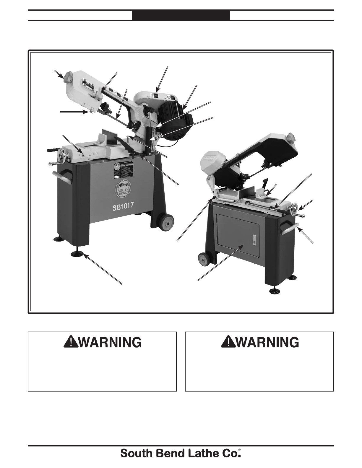
Identification
Blade Tension
Knob
Switch
Auto-Off
Tab
ON/OFF
Switch
Guide Post
Knob
Blade
Belt Cover
Downfeed
Stop Bolt
Work Stop
Motor
Downfeed
Rate Adjust
Knob
Downfeed
Ram
Vise
Jaw
Feed
Pressure
Handle
Vise Jaw
Handwheel
Front View
Locking Pin
Leveling Foot
Figure 1. Identification.
Serious personal injury could occur if
you connect the machine to power before
completing the setup process. DO NOT
connect power until instructed to do so later
in this manual.
Head
Cabinet Access
Door
Untrained users have an increased risk
of seriously injuring themselves with this
machine. Do not operate this machine until
you have understood this entire manual and
received proper training.
Transport
Handle
Rear View
-3-
Page 6

Model SB1017
Model SB1017
5" x 6" Horizontal/Vertical Bandsaw
Product Dimensions:
Weight .......................................................................................................................................................................... 166 lbs.
Length/Width/Height ............................................................................................................................. 38
3
⁄4" x 173⁄4" x 391⁄2"
Foot Print (Length/Width) ...................................................................................................................................38
3
⁄4" x 173⁄4"
Space Required for Full Range of Movement (Length/Width/Height) .......................................................... 80" x 55" x 78"
Shipping Dimensions:
Machine
Type ...................................................................................................................................................................... Carton
Weight ..................................................................................................................................................................170 lbs.
Length/Width/Height .............................................................................................................................. 42" x 17" x 16"
Stand
Type ...................................................................................................................................................................... Carton
Weight ....................................................................................................................................................................47 lbs.
Length/Width/Height .............................................................................................................................. 17" x 13" x 23"
Electrical:
Required Power Source .......................................................................................................110V/220V, Single-Phase, 60 Hz
Switch .................................................................................................................................................. Toggle ON/OFF Switch
Switch Voltage .................................................................................................................................................................. 110V
Cord Length ........................................................................................................................................................................ 6 ft.
Cord Gauge .................................................................................................................................................................18 gauge
Recommended Circuit Size ..........................................................................................................................................15 Amp
Plug Included .......................................................................................................................................................................Yes
Motors:
Main
Type ............................................................................................................................TEFC Capacitor Start Induction
Horsepower .............................................................................................................................................................
1
⁄2 HP
Voltage ............................................................................................................................................................110V/220V
Phase .......................................................................................................................................................... Single-Phase
Amps ................................................................................................................................................................... 8.6/4.3A
Speed ............................................................................................................................................................... 1725 RPM
Cycle .......................................................................................................................................................................60 Hz
Number Of Speeds ......................................................................................................................................................... 1
Pre-Wired ................................................................................................................................................................ 110V
Power Transfer .........................................................................................................................................V-Belt & Gear
Bearings ................................................................................................................... Shielded and Permanently Sealed
P.O. Box 2027, Bellingham, WA 98227 U.S.A.
PHONE: (360) 734-1540 • © South Bend Lathe Co.
www.southbendlathe.com
Machine Specifications
INTRODUCTION
For Machines Mfg. Since 8 /09
Machine Specifications
-4-
Page 7

For Machines Mfg. Since 8 /09 Model SB1017
Main Specifications:
Operation Information
Head Swivel..........................................................................................................................................................45 deg.
Blade Speeds ...................................................................................................................................... 80, 120, 200 FPM
Std. Blade Length ....................................................................................................................................................64
1
⁄2"
Blade Size Range .........................................................................................................................................................
1
⁄2"
Cutting Capacities
Angle Cuts ............................................................................................................................................................ 45 deg.
Vise Jaw Depth ......................................................................................................................................................... 6
5
⁄8"
Vise Jaw Height ........................................................................................................................................................ 2
5
⁄8"
Max. Capacity Rect. Height At 90D ........................................................................................................................... 5"
Max. Capacity Rect. Width At 90D ............................................................................................................................ 6"
Max. Capacity Rnd. At 90D ........................................................................................................................................ 5"
Max. Capacity Rect. Height At 45D ........................................................................................................................... 3"
Max. Capacity Rect. Width At 45D ......................................................................................................................... 4
1
⁄2"
Max. Capacity Rnd. At 45D ........................................................................................................................................ 3"
Construction
Wheel Construction Upper .............................................................................................................................. Cast Iron
Wheel Construction Lower .............................................................................................................................. Cast Iron
Body Construction ...........................................................................................................................................Cast Iron
Base Construction ............................................................................................................................................Cast Iron
Stand Construction ................................................................................................................................................. Steel
Tire Material .......................................................................................................................................Rubber and Steel
Other
Wheel Size .................................................................................................................................................................... 5"
Blade Guides Upper ...................................................................................................................................................Yes
Blade Guides Lower ...................................................................................................................................................Yes
Table Info
Floor to Cutting Area Height ................................................................................................................................. 25
1
⁄2"
Other Specifications:
ISO Factory ................................................................................................................................................................ ISO 9001
Country Of Origin ........................................................................................................................................................ Taiwan
Warranty .........................................................................................................................................................................1 Year
Serial Number Location .................................................................................................................. ID Label on Body Frame
Customer Setup and Cleaning Time .................................................................................................. Approximately 1 Hour
Features:
Heavy-Duty One-Piece Steel Stand
Conveniently Located ON/OFF Toggle Switch
Adjustable Hydraulic Down Feed
Cast Iron Handwheel with Chromed Handle
Die Cast South Bend Star Knobs
Die Cast South Bend Belt Guard
Built-In Storage Cabinet
Leveling Feet and Wheels to Ease Mobility
Work Stop for Horizontal Cuts
Satin Chromed Handle Bar
INTRODUCTION
-5-
Page 8

Model SB1017
Operating all machinery and machining equipment can be dangerous or relatively safe depending
on how it is installed and maintained, and the operator's experience, common sense, risk awareness,
working conditions, and use of personal protective equipment (safety glasses, respirators, etc.).
The owner of this machinery or equipment is ultimately responsible for its safe use. This
responsibility includes proper installation in a safe environment, personnel training and usage
authorization, regular inspection and maintenance, manual availability and comprehension,
application of safety devices, integrity of cutting tools or accessories, and the usage of approved
personal protective equipment by all operators and bystanders.
The manufacturer of this machinery or equipment will not be held liable for injury or property
damage from negligence, improper training, machine modifications, or misuse. Failure to read,
understand, and follow the manual and safety labels may result in serious personal injury, including
amputation, broken bones, electrocution, or death.
The signals used in this manual to identify hazard levels are defined as follows:
Death or catastrophic
harm WILL occur.
Moderate injury or fire
MAY occur.
Death or catastrophic
harm COULD occur.
Machine or property
damage may occur.
1. Owner’s Manual: All machinery and
machining equipment presents serious
injury hazards to untrained users. To
reduce the risk of injury, anyone who uses
THIS item MUST read and understand
this entire manual before starting.
2. Personal Protective Equipment:
Operating
or servicing this item may expose the user
to flying debris, dust, smoke, dangerous
chemicals, or loud noises. These hazards
can result in eye injury, blindness, longterm respiratory damage, poisoning,
cancer, reproductive harm or hearing loss.
Reduce your risks from these hazards
by wearing approved eye protection,
respirator, gloves, or hearing protection.
3. Trained/Supervised Operators Only:
Untrained users can seriously injure
themselves or bystanders. Only allow
trained and properly supervised personnel
to operate this item. Make sure safe
operation instructions are clearly
understood. If electrically powered, use
padlocks and master switches, and remove
start switch keys to prevent unauthorized
use or accidental starting.
4. Guards/Covers:
Accidental contact with
moving parts during operation may cause
severe entanglement, impact, cutting,
or crushing injuries. Reduce this risk by
keeping any included guards/covers/doors
installed, fully functional, and positioned
for maximum protection.
SAFETY
SAFETY
For Machines Mfg. Since 8 /09
Understanding Risks of Machinery
Basic Machine Safety
-6-
Page 9

For Machines Mfg. Since 8 /09 Model SB1017
5. Entanglement: Loose clothing, gloves,
neckties, jewelry or long hair may
get caught in moving parts, causing
entanglement, amputation, crushing,
or strangulation. Reduce this risk by
removing/securing these items so they
cannot contact moving parts.
6. Mental Alertness: Operating this item
with reduced mental alertness increases
the risk of accidental injury. Do not let a
temporary influence or distraction lead to a
permanent disability! Never operate when
under the influence of drugs/alcohol, when
tired, or otherwise distracted.
7. Safe Environment:
Operating electrically
powered equipment in a wet environment
may result in electrocution; operating near
highly flammable materials may result in a
fire or explosion. Only operate this item in
a dry location that is free from flammable
materials.
8. Electrical Connection: With electically
powered equipment, improper connections
to the power source may result in
electrocution or fire. Always adhere to all
electrical requirements and applicable
codes when connecting to the power source.
Have all work inspected by a qualified
electrician to minimize risk.
9. Disconnect Power: Adjusting or servicing
electrically powered equipment while it
is connected to the power source greatly
increases the risk of injury from accidental
startup. Always disconnect power
BEFORE any service or adjustments,
including changing blades or other tooling.
10. Secure Workpiece/Tooling:
Loose
workpieces, cutting tools, or rotating
spindles can become dangerous projectiles
if not secured or if they hit another object
during operation. Reduce the risk of this
hazard by verifying that all fastening
devices are properly secured and items
attached to spindles have enough clearance
to safely rotate.
11. Chuck Keys or Adjusting Tools:
Tools used
to adjust spindles, chucks, or any moving/
rotating parts will become dangerous
projectiles if left in place when the machine
is started. Reduce this risk by developing
the habit of always removing these tools
immediately after using them.
12. Work Area:
Clutter and dark shadows
increase the risks of accidental injury.
Only operate this item in a clean, nonglaring, and well-lighted work area.
13. Properly Functioning Equipment:
Poorly
maintained, damaged, or malfunctioning
equipment has higher risks of causing
serious personal injury compared to
those that are properly maintained.
To reduce this risk, always maintain
this item to the highest standards and
promptly repair/service a damaged or
malfunctioning component. Always follow
the maintenance instructions included in
this documentation.
14. Unattended Operation:
Electrically
powered equipment that is left unattended
while running cannot be controlled and is
dangerous to bystanders. Always turn the
power OFF before walking away.
15. Health Hazards: Certain cutting fluids
and lubricants, or dust/smoke created
when cutting, may contain chemicals
known to the State of California to cause
cancer, respiratory problems, birth defects,
or other reproductive harm. Minimize
exposure to these chemicals by wearing
approved personal protective equipment
and operating in a well ventilated area.
16. Difficult Operations:
Attempting
difficult operations with which you are
unfamiliar increases the risk of injury.
If you experience difficulties performing
the intended operation, STOP! Seek an
alternative method to accomplish the
same task, ask a qualified expert how the
operation should be performed, or contact
our Technical Support for assistance.
SAFETY
-7-
Page 10

Model SB1017
SAFETY
Additional Metal Bandsaw Safety
For Machines Mfg. Since 8 /09
1. Blade Condition. A dull or damaged
blade can break apart during operation,
increasing the risk of operator injury. Do
not operate with a dull, cracked or badly
worn blade. Inspect the blade for cracks
or missing teeth before each use.
2. Hand Placement. Hands could be cut
by the blade or crushed when lowering
the headstock. Never position fingers or
thumbs in line with the cut or under the
headstock while it is moving.
3. Blade Guard. Hands and fingers can
easily be cut by the bandsaw blade. To
reduce the risk of laceration injuries, do
not operate this bandsaw without the
blade guard in place.
4. Starting Position. To reduce the
likelihood of blade breakage and possible
entanglement, never turn the saw ON
with the blade resting on the workpiece.
5. Blade Replacement. The blade can
only make a safe and efficient cut if the
teeth are facing the workpiece. When
replacing blades, make sure the teeth
face toward the workpiece. Wear gloves
to protect hands and safety glasses to
protect eyes.
6. Workpiece Handling. A shifting workpiece
can result in impact or laceration injuries.
To reduce the risk of injury, always securely
clamp the workpiece in the vise and use
additional support fixtures if needed. Never
hold the workpiece with your hands during
a cut. Flag long pieces to reduce the risk of
tripping over them.
7. Power Interruption. Unplug the machine
and turn the power switch OFF after a
power interruption. If left plugged in and
turned ON, this machine will start up when
power is restored, resulting in possible
entanglement, laceration, or amputation
hazards.
8. Hot Surfaces/Sharp Edges. Due to the
cutting process, a freshly cut workpiece,
chips, and some machine components
can be hot enough to burn you and sharp
enough to cut you. Allow components to cool
and use safe handling methods to reduce
the risk of these injuries.
9. Moving Blade. A moving bandsaw blade
presents a serious risk for laceration or
amputation injuries. Always allow the blade
to come to a complete stop before mounting
or repositioning a workpiece in the vise.
Never touch a moving blade.
-8-
Page 11

For Machines Mfg. Since 8 /09 Model SB1017
Before installing the machine, consider the
availability and proximity of the required power
supply circuit. If an existing circuit does not meet
the requirements for this machine, a new circuit
must be installed.
To minimize the risk of electrocution, fire,
or equipment damage, installation work and
electrical wiring must be done by a qualified
electrician in accordance with all applicable
codes and standards.
The full-load current rating is the amperage
a machine draws at 100% of the rated output
power. On machines with multiple motors, this is
the amperage drawn by the largest motor or sum
of all motors and electrical devices that might
operate at one time during normal operations.
The full-load current is not the maximum
amount of amps that the machine will draw. If
the machine is overloaded, it will draw additional
amps beyond the full-load rating.
If the machine is overloaded for a sufficient
length of time, damage, overheating, or fire may
result—especially if connected to an undersized
circuit. To reduce the risk of these hazards,
avoid overloading the machine during operation
and make sure it is connected to a power supply
circuit that meets the requirements in the
following section.
PREPARATION
Preparation Overview
PREPARATION
Power Supply
The purpose of the preparation section is to help
you prepare your machine for operation. The
list below outlines the basic process to follow
to prepare your machine for operation. Specific
steps for each of these points will be covered in
detail later in this section.
The typical preparation process is as follows:
1. Unpack the machine and inventory the
contents of the carton.
2. Clean the machine and its components.
3. Make any necessary adjustments or
inspections to ensure the machine is ready
for operation.
4. Connect the machine to the power source.
5. Test run the machine to make sure it
functions properly and is ready for operation.
Required for Setup
The items listed below are required to
successfully set up and prepare this machine for
operation.
Requirements
Availability
Electrocution or fire may
occur if machine is not
correctly grounded and
attached to the power
supply. Use a qualified
electrician to ensure a safe
power connection.
Full-Load Current Rating
For Power Connection
• Apowersourcethatmeetstheminimum
circuit requirements for this machine. (Refer
to the Power Supply Requirements
section for details.)
• Aqualifiedelectriciantoensureasafeand
code-compliant connection to the power
source.
Full-Load Rating at 110V .................. 8.6 Amps
Full-Load Rating at 220V .................. 4.3 Amps
-9-
Page 12
Model SB1017
This machine is prewired to operate on a 110V
power supply circuit that has a verified ground
and meets the following requirements:
For your own safety and protection of property,
consult a qualified electrician if you are unsure
about wiring practices or electrical codes in
your area.
Note: The circuit requirements listed in this
manual apply to a dedicated circuit—where only
one machine will be running at a time. If this
machine will be connected to a shared circuit
where multiple machines will be running at
the same time, consult a qualified electrician to
ensure that the circuit is properly sized for safe
operation.
A power supply circuit includes all electrical
equipment between the main breaker box or fuse
panel in your building and the incoming power
connections inside the machine. This circuit must
be safely sized to handle the full-load current
that may be drawn from the machine for an
extended period of time.
This machine can be converted to operate on
a 220V power supply. To do this, follow the
Voltage Conversion instructions included in
this manual. The intended 220V circuit must
have a verified ground and meet the following
requirements:
In the event of certain types of malfunctions or
breakdowns, grounding provides a path of least
resistance for electric current—in order to reduce
the risk of electric shock.
Grounding Prong
Current Carrying Prongs
5-15 PLUG
GROUNDED
5-15 RECEPTACLE
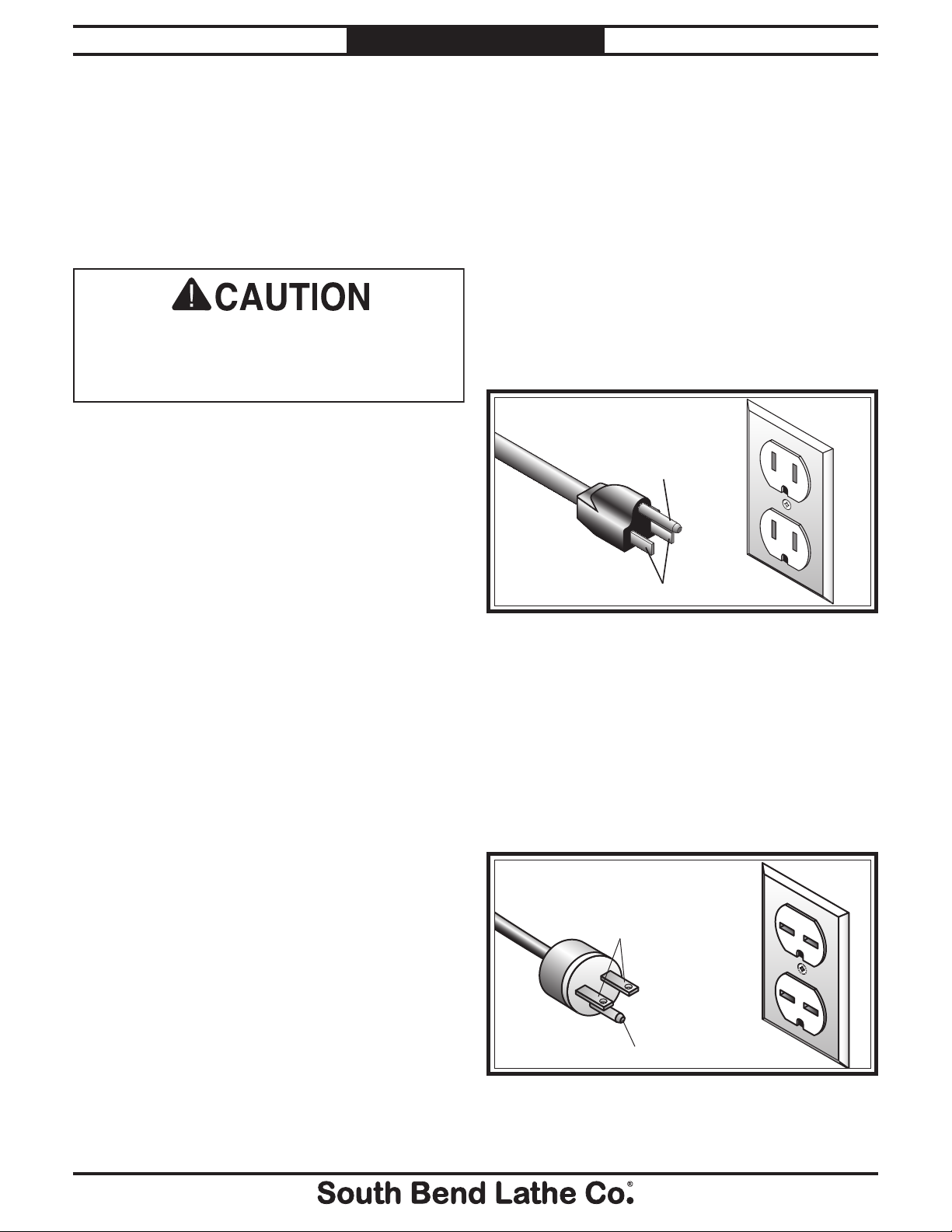
This machine is equipped with a power cord
that has an equipment-grounding wire and a
grounding plug (similar to the figure below).
The plug must only be inserted into a matching
receptacle (outlet) that is properly installed and
grounded in accordance with all local codes and
ordinances.
Use the plug type listed in the Circuit
Requirements for this voltage. The listed plug
(similar to the figure below) has an equipmentgrounding wire to safely ground the machine.
The plug must only be inserted into a matching
receptacle (outlet) that is properly installed and
grounded in accordance with all local codes and
ordinances.
Grounding Prong
Current Carrying Prongs
6-15 PLUG
GROUNDED
6-15 RECEPTACLE
PREPARATION
For Machines Mfg. Since 8 /09
Circuit Information
Grounding Requirements
For 110V Connection (Prewired)
Circuit Requirements for 110V
Nominal Voltage ...............................110V/120V
Cycle .............................................................60 Hz
Phase .............................................. Single-Phase
Circuit Rating....................................... 15 Amps
Plug/Receptacle (included) ...........NEMA 5-15
Circuit Requirements for 220V
Nominal Voltage ...............................220V/240V
Cycle .............................................................60 Hz
Phase .............................................. Single-Phase
Circuit Rating....................................... 15 Amps
Plug/Receptacle ...............................NEMA 6-15
-10-
Figure 2. NEMA 5-15 plug and receptacle.
For 220V Connection
Figure 3. NEMA 6-15 plug and receptacle.
Page 13

For Machines Mfg. Since 8 /09 Model SB1017
Serious injury could occur if you connect
the machine to power before completing the
setup process. DO NOT connect to power until
instructed later in this manual.
Improper connection of the equipment-grounding
wire can result in a risk of electric shock. The
wire with green insulation (with or without
yellow stripes) is the equipment-grounding wire.
If repair or replacement of the power cord or
plug is necessary, do not connect the equipmentgrounding wire to a live (current carrying)
terminal.
Check with a qualified electrician or service
personnel if you do not understand these
grounding requirements, or if you are in doubt
about whether the tool is properly grounded.
If you ever notice that a cord or plug is
damaged or worn, disconnect it from power, and
immediately replace it with a new one.
We do not recommend using an extension cord
with this machine. If you must use one, only
use it if absolutely necessary and only on a
temporary basis.
Extension cords cause voltage drop, which may
damage electrical components and shorten motor
life. Voltage drop increases as the extension cord
size gets longer and the gauge size gets smaller
(higher gauge numbers indicate smaller sizes).
Any extension cord used with this machine
must contain a ground wire, match the required
plug and receptacle listed in the Circuit
Requirements for the applicable voltage, and
meet the following requirements:
PREPARATION
Extension Cords
Minimum Gauge Size ............................16 AWG
Maximum Length (Shorter is Better) .... 50 ft.
-11-
Page 14
Model SB1017
This item was carefully packaged to prevent
damage during transport. If you discover any
damage, please immediately call Customer
Service at (360) 734-1540 for advice. You may
need to file a freight claim, so save the containers
and all packing materials for possible inspection
by the carrier or its agent.
PREPARATION
For Machines Mfg. Since 8 /09
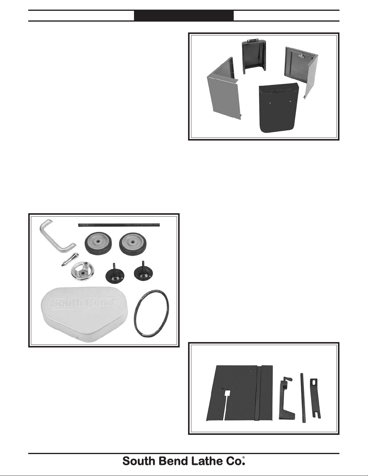
Unpacking
Inventory
Description (Figure 4) Qty
A. Handle ............................................................1
B. Axle ................................................................. 1
C. Wheels ............................................................2
D. Leveling Feet ..................................................2
E. Handwheel .....................................................1
F Handwheel Handle ........................................1
G. Pulley Cover ................................................... 1
H. V-Belt ..............................................................1
A
B
C
J
I
K
L
Figure 5. Stand components.
Hardware (Not Shown) Qty
• Hex Nut
• Flat Head Screw
(Vertical Operation) .......................................1
• Hex Wrench 4mm .......................................... 1
• HexBoltM8-1.25 x 15 .................................21
• HexNutM8-1.25 .......................................... 19
• Flat Washer 8mm ........................................40
• HexBoltM12-1.75 x 25 ................................4
• Flat Washer 12mm ........................................5
• KnobM6-1x15 ..............................................1
• CotterPins ..................................................... 2
1
⁄4"-20 (Vertical Operation) ............. 1
1
⁄4"-20 x 1⁄2"
F
G
Figure 4. Small components.
Description (Figure 5) Qty
I. Rear Panel ......................................................1
J. Right Side Panel ............................................ 1
K. Front Panel .....................................................1
L. Left Side Panel ...............................................1
-12-
E
D
The items listed below are optional components
and are not required for bandsaw operations.
Their installation and use is covered in
Operation, beginning on Page 19. Parts A and
D are required for Vertical Cutting (Page 30).
H
Description Qty
M. Table (Vertical Operation) .............................1
N. Work Stop ....................................................... 1
O. Work Stop Rod ...............................................1
P. Table Support (Vertical Operation) .............. 1
M
O
P
N
Figure 6. Optional components.
Page 15
For Machines Mfg. Since 8 /09 Model SB1017
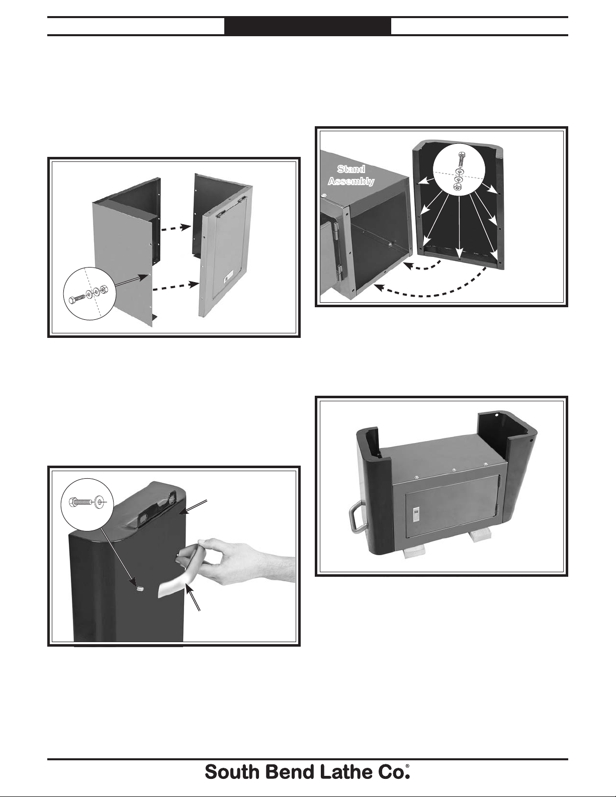
Assembly
To assemble the bandsaw:
1. Attach the front and rear panels of the stand
together as shown in Figure 7 with (6) M8-
1.25 x 15 hex bolts, (6) M8-1.25 hex nuts hex
nuts, and (12) 8mm flat washers.
Rear Panel
PREPARATION
4. Attach the right side panel (the side without
the handle) to the stand assembly as shown
in Figure 9 with (7) M8-1.25 x 15 hex bolts,
(7) M8-1.25 hex nuts, and (14) 8mm flat
washers.
Stand
Assembly
x7
Right Side
Panel
x6
Figure 7. Front and rear panel assembly.
2. Place the assembly upside down on wood
blocks to avoid scratching it or damaging the
mounting tabs.
3. Attach the handle to the left side panel as
shown in Figure 8 with two M8-1.25 x 15
hex bolts and 8mm flat washers.
x2
Front Panel
Left Side Panel
Figure 9. Left side panel assembly.
5. Repeat the above step for the right side
panel using (6) M8-1.25 x 15 hex bolts,
(6) M8-1.25 hex nuts, and (12) 8mm flat
washers (see Figure 10 for assembled view).
Figure 10. Stand assembly.
Handle
Figure 8. Handle installation.
-13 -
Page 16
Model SB1017
PREPARATION
For Machines Mfg. Since 8 /09
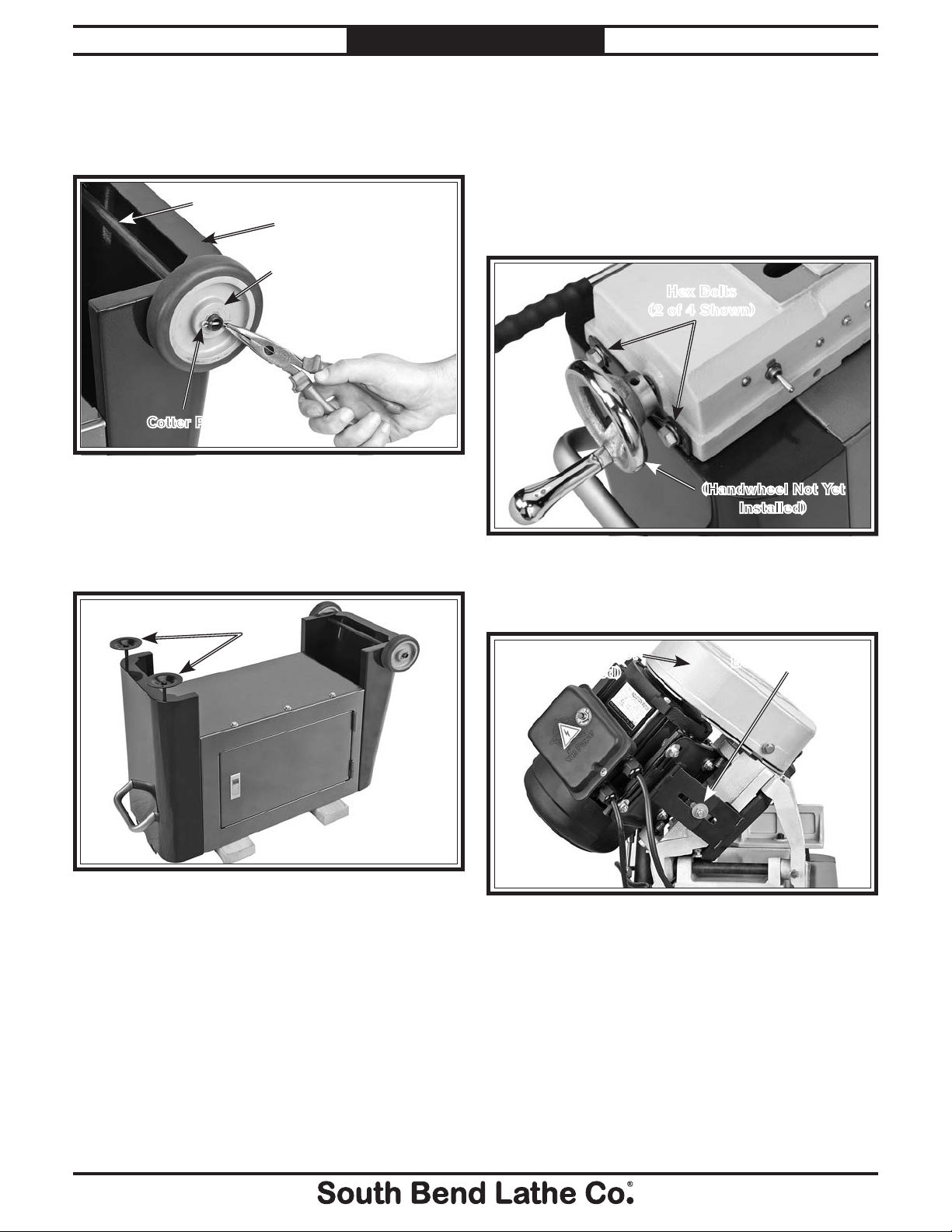
6. Insert the axle through the holes in the base
assembly, then slide the wheels over the axle
and secure each with a cotter pin, as shown
in Figure 11.
Axle
Base
Wheel
Cotter Pin
Figure 11. Wheel assembly.
7. Thread the leveling feet into the stand
assembly, as shown in Figure 12. You can
adjust these later as needed to level the
bandsaw.
Leveling
Feet
8. With the help of another person, flip the
stand assembly right-side up, then lift the
bandsaw assembly and place it onto the
stand assembly.
9. Secure the bandsaw to the stand with four
M12-1.75 x 25 hex bolts and 12mm flat
washers, as shown in Figure 13.
Hex Bolts
(2 of 4 Shown)
(Handwheel Not Yet
Installed)
Figure 13. Mounting bandsaw to stand.
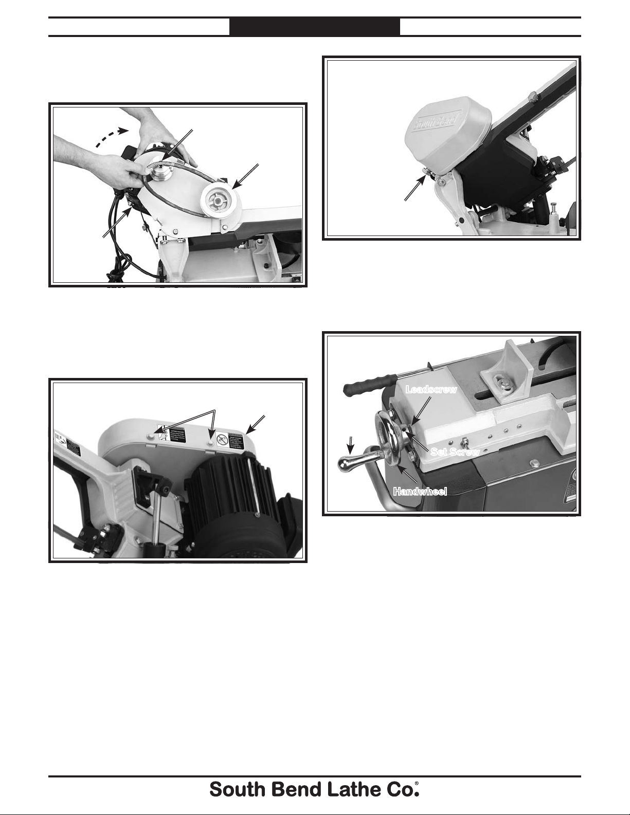
10. Loosen the belt tension bolt shown in Figure
14.
(Pulley Cover Not
Yet Installed)
Belt Tension Bolt
-14-
Figure 12. Leveling feet.
Figure 14. Belt tension bolt location.
Page 17
For Machines Mfg. Since 8 /09 Model SB1017
PREPARATION
11. Pivot the motor assembly upward, then place
the belt over the gearbox and motor pulleys,
as shown in Figure 15.
Motor Pulley
Gearbox
Pulley
Knob Location
Motor
Assembly
Figure 17. Pulley cover knob.
13. Slide the vise handwheel onto the leadscrew
Figure 15. Installing belt.
12. Install the pulley cover (Figure 16) with two
and tighten the set screw shown in Figure
18. Thread the handle into the handwheel
and tighten it.
M6-1 x 12 hex bolts, three 6mm flat washers,
and the South Bend cast aluminum knob
(see Figure 17).
Hex Bolts
Figure 16. Pulley cover.
Belt
Cover
Leadscrew
Handle
Set Screw
Handwheel
Figure 18. Vise handwheel.
-15 -
Page 18

Model SB1017
The unpainted surfaces are coated at the factory
with a heavy-duty rust preventative that
prevents corrosion during shipment and storage.
The benefit of this rust preventative is that it
works very well. The downside is that it can be
time-consuming to thoroughly remove.
Be patient and do a careful job when cleaning
and removing the rust preventative. The time
you spend doing this will reward you with
smooth-sliding parts and a better appreciation
for the proper care of the unpainted surfaces.
Although there are many ways to successfully
remove the rust preventative, we have cleaned
thousands of machines and found the following
process to be the best balance between efficiency
and minimized exposure to toxic fumes or
chemicals.
Before cleaning, gather the following:
• Disposablerags
• Cleaner/degreaser (certain citrus-based
degreasers work extremely well and they
have non-toxic fumes)
• Safetyglasses&disposablegloves
Note: Automotive degreasers, mineral spirits, or
WD•40canbeusedtoremoverustpreventative.
Before using these products, though, test them
on an inconspicuous area of a painted area to
make sure they will not damage it.
Basic steps for removing rust preventative:
1. Put on safety glasses and disposable gloves.
2. Coatallsurfacesthathaverustpreventative
with a liberal amount of your cleaner or
degreaser and let them soak for a few
minutes.
3. Wipe off the surfaces. If your cleaner or
degreaser is effective, the rust preventative
will wipe off easily.
Note: To clean off thick coats of rust preventative
on flat surfaces, such as beds or tables, use
aPLASTICpaintscrapertoscrapeoffthe
majority of the coating before wiping it off
withyourrag.(Donotuseametalscraperor
it may scratch the surface.)
4. Repeat Steps 2–3 as necessary until clean,
then coat all unpainted surfaces with a
quality metal protectant or light oil to
prevent rust.
GAS
Gasoline and petroleum
products have low flash
points and can explode
or cause fire if used for
cleaning. Avoid using these
products to remove rust
preventative.
Many cleaning solvents are
toxic if inhaled. Minimize
your risk by only using
these products in a well
ventilated area.
Avoid chlorine-based solvents, such as
acetone or brake parts cleaner that may
damage painted surfaces. Always follow the
manufacturer’s instructions when using any
type of cleaning product.
PREPARATION
Cleaning & Protecting
For Machines Mfg. Since 8 /09
-16 -
Page 19

For Machines Mfg. Since 8 /09 Model SB1017
Power
Connection
38"6" Min.
19"
16¾"
35¾"
Wall
(Drawing Not to Scale)
Weight Load
Refer to the Machine Specifications for the
weight of your machine. Make sure that the
surface upon which the machine is placed will
bear the weight of the machine, additional
equipment that may be installed on the machine,
and the heaviest workpiece that will be used.
Additionally, consider the weight of the operator
and any dynamic loading that may occur when
operating the machine.
Space Allocation
Consider the largest size of workpiece that will
be processed through this machine and provide
enough space around the machine for adequate
operator material handling or the installation
of auxiliary equipment. With permanent
installations, leave enough space around
the machine to open or remove doors/covers
as required by the maintenance and service
described in this manual.
Physical Environment
The physical environment where your machine
is operated is important for safe operation and
longevity of parts. For best results, operate this
machine in a dry environment that is free from
excessive moisture, hazardous or flammable
chemicals, airborne abrasives, or extreme
conditions. Extreme conditions for this type
of machinery are generally those where the
ambient temperature is outside the range of 41°–
104°F; the relative humidity is outside the range
of 20–95% (non-condensing); or the environment
is subject to vibration, shocks, or bumps.
Electrical Installation
Place this machine near an existing power
source. Make sure all power cords are protected
from traffic, material handling, moisture,
chemicals, or other hazards. Make sure to leave
access to a means of disconnecting the power
source or engaging a lockout/tagout device.
Lighting
Lighting around the machine must be adequate
enough that operations can be performed
safely. Shadows, glare, or strobe effects that
may distract or impede the operator must be
eliminated.
Children or untrained
people may be seriously
injured by this machine.
Only install in an access
restricted location.
PREPARATION
Location
Physical Environment
Electrical Installation
Lighting
Weight Load
Space Allocation
Figure 19. Clearances.
-17-
Page 20

Model SB1017
PREPARATION
Power Connection
Electrocution or fire
may occur if machine is
ungrounded, incorrectly
connected to power, or
connected to an undersized
circuit. Use a qualified
electrician to ensure a safe
power connection.
Once your machine is set up and assembled as
previously described in this manual, it is ready to
be connected to the power source.
• Ifyouplantousethemachineat110V,
simply plug it into a receptacle on a 110V
circuit that meets the requirements listed on
Page 10.
• Ifyouplantousethemachineat220V,you
will have to convert the machine for 220V.
Refer to Electrical, beginning on Page 41.
For Machines Mfg. Since 8 /09
3. Open the downfeed valve and allow the
saw to travel all the way down. If the blade
contacts the machine base or the autoOFF tab rests on the toggle switch, adjust
the downfeed stop bolt as described in
Downfeed Stop Bolt, on Page 35.
4. Connect the machine to the power source.
5. Put on safety glasses and secure loose
clothing or long hair.
6. Lift the bandsaw by the handle. Close the
downfeed valve to prevent it from lowering.
7. Start the bandsaw while keeping your finger
near the ON/OFF toggle switch at all times
during the test run. The bandsaw should run
smoothly with little or no vibration.
— If you suspect any problems, immediately
turn the bandsaw OFF, disconnect it from
power, and correct the problem before
continuing.
— If you need any help with your bandsaw
call our Tech Support at (360) 734-1540.
Test Run
After all preparation steps have been completed,
the machine and its safety features must be
tested to ensure correct operation. If you discover
a problem with the operation of the machine or
its safety components, do not operate it further
until you have resolved the problem.
Note: Refer to Troubleshooting on Page 38 for
solutions to common problems that occur with
metal-cutting bandsaws. If you need additional
help, contact our Tech Support at (360) 734-1540.
To test run your machine:
1. Read and follow the safety instructions at
the beginning of the manual, take required
safety precautions, and make sure the
machine is set up and adjusted properly
2. Clear away all tools and objects used during
assembly and preparation.
8. Open the downfeed valve to lower the saw
through its full range of motion. When it
reaches the bottom of its travel, it should
turn OFF. If it does not, manually turn it
OFF, disconnect it from power, then proceed
immediately to Auto-Off Tab, on Page 37.
Inspections &
Adjustments
The following list of adjustments were performed
at the factory before your machine was shipped.
If you find that the adjustments are not set
according to the procedures in this manual or
your personal preferences, re-adjust them.
• Blade Tracking .................................Page 35.
• Squaring the Blade ..........................Page 37.
• BladeGuideBearings ......................Page 36.
-18 -
Page 21

For Machines Mfg. Since 8 /09 Model SB1017
To reduce the risk of
serious injury when using
this machine, read and
understand this entire
manual before beginning
any operations.
The purpose of this overview is to provide
the novice machine operator with a basic
understanding of how the machine is used during
operation, so they can more easily understand
the controls discussed later in this manual.
Note: Due to the generic nature of this overview,
it is not intended to be an instructional guide
for performing actual machine operations.
To learn more about specific operations and
machining techniques, seek training from people
experienced with this type of machine, and do
additional research outside of this manual by
reading "how-to" books, trade magazines, or
websites.
OPERATION
OPERATION
Operation Overview
To complete a typical operation, the operator
does the following:
1. Examines the workpiece to make sure it is
suitable for cutting.
2. Checks/adjusts the V-belt position on the
pulleys to ensure the correct cutting speed
for the workpiece.
3. Raises the head, then closes the downfeed
valve.
4. Adjusts the vise angle for the operation, then
securely clamps the workpiece in the vise.
5. Lowers the saw bow close to the workpiece,
then adjusts the guide post to within 1" of
the workpiece, and verifies that the blade is
properly tensioned.
6. Adjusts the guide post so the opening
between the two blade guides is
approximately
the workpiece.
1
⁄4" larger than the width of
Loose hair, clothing, or
jewelry could get caught
in machinery and cause
serious personal injury.
Keep these items away
from moving parts at all
times to reduce this risk.
During operation, small
metal chips may become
airborne, leading to serious
eye injury. Wear safety
glasses to reduce this risk.
7. Makes sure the workpiece and bandsaw are
stable and that there are no obstructions in
the way of the cut.
8. Puts on safety glasses.
9. Starts the bandsaw and waits for the blade
to reach full speed.
10. Opens the downfeed valve to lower the head
and blade into the workpiece, then allows
the bandsaw to complete the cut.
11. Once the bandsaw has stopped, raises the
head, and removes the workpieces.
-19 -
Page 22

Model SB1017
OPERATION
For Machines Mfg. Since 8 /09
Controls
Refer to Figures 20–21 and the following
descriptions to become familiar with the basic
controls of this machine.
Blade Tension Knob: Adjusts the position
A.
of the upper blade wheel to apply or release
blade tension.
Guide Post Knob: Locks the guide post in
B.
the position set by the operator.
Downfeed Rate Adjust Knob: Controls
C.
the speed at which the blade lowers into the
workpiece.
Downfeed Valve: Controls the starting and
D.
stopping of the headstock downfeed.
Work Stop Lock Knob: Locks the work stop
E.
in the position set by the operator.
I. He
J. V
K. F
L. Transport Handle: Provides a solid control
M.
N. Vi
ad Locking Pin: Can be inserted into one
of three holes to lock the head in the down,
up, or vertical positions.
ise Jaw Lock Bolt: Locks the vise jaw at
the angle set by the operator.
eed Pressure Handle: Controls the feed
pressure by increasing or decreasing preload
on the feed pressure spring.
point for moving the machine.
Fence Scale: Indicates the angle of the vise
fence.
se Fence Bolts (behind fence): Lock the
fence at the angle set by the operator.
J
K
ON/OFF Toggle Switch: Turns the saw
F.
motor ON or OFF.
ise Jaw Handwheel: Controls the vise jaw
G. V
movement.
ownfeed Stop Bolt: Adjusts to determine
H. D
the absolute bottom limit of blade travel.
B
A
G
F
H
I
N
C
D
E
Figure 21. Rear Identification.
M
L
-20-
Figure 20. Front Identification.
Page 23

For Machines Mfg. Since 8 /09 Model SB1017
A
B
C
D
E
F
G
H
I
Blade Selection
Selecting the right blade for the cut requires a
knowledge of various blade characteristics. This
section breaks down blade characteristics to help
the reader make an informed decision about
what blade to use for a given operation.
OPERATION
E. T
ooth Rake: The angle of the tooth face
from a line perpendicular to the length of the
blade.
ullet Depth: The distance from the tooth
F. G
tip to the bottom of the curved area (gullet).
Tooth Pitch: The distance between tooth
G.
tips.
Blade Terminology
Blade Back: The distance between the
H.
bottom of the gullet and the back edge of the
blade.
lade Pitch or TPI: The number of teeth per
I. B
inch measured from gullet to gullet.
Blade Length
Measured by the blade circumference, blade
lengths are usually unique to the brand of your
bandsaw and the distance between the wheels.
Figure 22. Bandsaw blade terminology.
A. Kerf: The width of the cut made during
operation.
B. Too
C. G
D. Bl
th Set: The distance each tooth is bent
left or right from the blade.
auge: The thickness of the blade.
ade Width: The widest point of the blade
measured from the tip of the tooth to the
back edge of the blade.
Model Blade Length
SB1017 .............................................................64
1
⁄2"
Blade Width
Measured from the back of the blade to the tip
of the blade tooth (the widest point), blade width
is often the first consideration given to blade
selection. Blade width dictates the largest and
smallest curve that can be cut, as well as how
accurately it can cut a straight line—generally
the wider the blade, the straighter it will cut.
Model Blade Width
SB1017 .................................................................
Curve Cutting: Curve cutting can only be
performed while the machine is in the vertical
position. See Vertical Operation on Page 30
for more information on vertical cutting. The
smallest radius curve that can accurately be cut
with a
1
⁄2" blade width is approximately 2 1⁄2".
1
⁄2"
-21-
Page 24

Model SB1017
Standard (or Raker)
Variable Pitch (VP)
Variable Pitch Positive Rake
Hook (or Claw)
Skip (or Skip Tooth)
Alternate
Wavy
Raker
OPERATION
Tooth Set
Three common tooth sets are alternate, wavy,
and raker (see Figure 23). Each removes
material in a different manner when cutting the
workpiece.
For Machines Mfg. Since 8 /09
Figure 23. Bandsaw blade tooth sets.
Alternate: An all-purpose arrangement of
bending the teeth evenly left and right of the
blade. Generally used for milder metals.
Wavy: Generally three or more teeth in a group
that are bent one way, followed by a non-set
tooth, and then a group bent the other way.
Recommended for straight cuts in thin metals or
thin-wall tubing.
Raker: Three teeth in a recurring group—one
bent left, next one bent right, and then a nonset tooth. The raker set is ideal for most contour
cuts.
Tooth Type
The most common tooth types are described
below and illustrated in Figure 24.
Standard or Raker: Equally spaced teeth set at
a "0" rake angle. Recommended for all purpose
use.
Figure 24. Bandsaw blade tooth types.
Variable Pitch (VP): Varying gullet depth and
tooth spacing, a "0" rake angle, excellent chip
removing capacity, and smooth cutting.
Variable Pitch with Positive Rake: Varying
gullet depth and tooth spacing, a positive rake
angle, better chip formation, and aggressive
cutting.
Hook or Claw: Wide gullets (round or flat),
equally spaced teeth, positive rake angle, and
fast cut with good surface finish.
Skip or Skip Tooth: Wide, flat gullets, a "0" rake
angle, equally spaced teeth, and recommended
for non-ferrous materials.
-22-
Page 25

For Machines Mfg. Since 8 /09 Model SB1017
TOOTH SELECTION
50
2 3 4 5 6 7 8 9 10 11 12 13 14 15 16 17 18 192½ 3½
75 100 150 200 250 300 350 400
2/3
2/3
2/3 1.4/2.5
1.4/2.5
1.5/.8
1.5/.8
3/4
3/4
3/4
4/6
4/6
5/8
450
mm
inch
OPERATION
Blade Pitch (TPI)
The chart below is a basic starting point for
choosing teeth per inch (TPI) for variable pitch
blades and standard raker set bi-metal blades/
HSS blades. However, for exact specifications
of bandsaw blades that are correct for your
operation, contact the blade manufacturer.
To select the correct blade pitch:
1. Measure the material thickness. This
measurement is the distance from where
each tooth enters the workpiece to where it
exits the workpiece.
Material Width/Diameter
Material Shapes
2. Refer to the "Material Width/Diameter"
row of the blade selection chart in Figure
25, and read across to find the workpiece
thickness you need to cut.
3. Refer to the "Material Shapes" row and find
the shape of the material to be cut.
4. In the applicable row, read across to the
right and find the box where the row and
column intersect. Listed in the box is the
minimum TPI recommended for the variable
tooth pitch blades.
Teeth Per Inch (TPI) for Bandsaw Blades
Figure 25. General guidelines for blade selection and speed chart.
-23-
Page 26

Model SB1017
!
Blade Travel
!
OPERATION
Blade Changes
Change blades when they become dull, damaged,
or if the operation requires a different type of
blade.
To change the blade on the bandsaw:
1. DISCONNECT BANDSAW FROM POWER!
2. Raise the head of the bandsaw to the vertical
position, use the head locking pin to hold it
in place, then remove the wheel access cover.
For Machines Mfg. Since 8 /09
3. Loosen the tension knob and slip the blade
off of the wheels.
4. Install the new blade through both blade
guide bearings, as shown in Figure 26, and
around the bottom wheel.
Blade
Guide
Bearings
Figure 26. Installing blade.
Figure 27. Blade cutting direction.
6. When the blade is around both wheels,
adjust the position so the back of the blade is
against the shoulder of the wheels as shown
in Figure 28.
Wheel Shoulder
Figure 28. Installing blade around wheel.
5. Hold the blade around the bottom wheel with
one hand and slip it around the top wheel with
the other hand, keeping the blade between the
blade guide bearings.
Note: It is sometimes possible to flip the
blade inside out, in which case the blade will
be installed in the wrong direction. Check to
make sure the blade teeth are facing toward
the workpiece, as shown in Figure 27, after
mounting to the bandsaw. Some blades will
have a directional arrow as a guide.
-24-
7. Tighten the tension knob so the blade will
not slip on the wheels upon startup.
8. Connect the bandsaw to the power source.
9. Briefly turn the bandsaw ON then OFF to
position the blade and resume the previous
tracking.
— If the tracking needs to be adjusted, see
Blade Tracking on Page 35.
— If the tracking is fine, proceed to Blade
Tension on Page 25.
Page 27

For Machines Mfg. Since 8 /09 Model SB1017
!
OPERATION
blade selection
Blade Tension
Proper tension is essential to avoid vibration,
twist, or`slippage on the wheels. A correctly
tensioned blade provides long life, straight cuts,
and efficient cutting times.
The three major signs of incorrect tension are:
1) The blade stalls in the cut and slips on the
wheels, 2) the blade frequently breaks, and 3) the
cuts are not straight.
To tension the blade on the bandsaw:
1. Make sure the blade is tracking properly
(refer to Blade Tracking on Page 35).
2. DISCONNECT BANDSAW FROM POWER!
3. Loosen and slide the blade guide as far out
as it will go, then tighten it down again.
4. Turn the tension knob in Figure 29
clockwise to tighten the blade or clockwise to
loosen the blade.
Blade
Tension
Knob
Blade Breakage
Many conditions may cause a bandsaw blade to
break. Some of these conditions are unavoidable
and are the natural result of the stresses to
which bandsaw blades are subjected. Other
causes of blade breakage are avoidable.
The most common causes of avoidable blade
breakage are:
• Faulty alignment or adjustment of the blade
guides.
• Forcing or twisting a wide blade around a
tight radius.
• Feeding the workpiece too fast.
• Dull or damaged teeth.
• Over-tensioned blade.
• Top blade guide assembly set too high above
the workpiece. Adjust the top blade guide
assembly so that there is approximately
between the bottom of the assembly and the
workpiece. Understand that with smaller
workpieces, this may not be possible. In
these cases, simply adjust the blade guide as
far down as possible.
1
⁄4"
Figure 29. Adjusting blade tension.
5. Using moderate finger pressure, push
against the side of the blade. If the blade
flexes more than
tension knob further, then repeat this step.
1
⁄8", tighten the blade
• Using a blade with a lumpy or improperly
finished braze or weld.
• Continuously running the bandsaw when not
in use.
• Leaving the blade tensioned when not in use.
• Using the wrong blade pitch (TPI) for the
workpiece thickness. The general rule of
thumb is to have no fewer than three teeth
in contact with the workpiece when cutting.
-25-
Page 28

Model SB1017
Gearbox Pulley Motor Pulley
80 FPM
120 FPM
200 FPM
OPERATION
For Machines Mfg. Since 8 /09
Blade Care & Break-In
Blade Care
To prolong blade life, always use a blade with
the proper width, set, type, and pitch for each
application. Maintain the appropriate feed
rate,feedpressure,andbladespeed.Keepyour
blades clean, since dirty or gummed up blades
pass through the cutting material with much
more resistance than clean blades, causing
unnecessary heat.
Blade Break-In
The tips and edges of a new blade are extremely
sharp. Cutting at too fast of a feed rate or too
slow of a blade speed can fracture these tips and
edges, causing the blade to quickly become dull.
Properly breaking-in a blade allows these sharp
edges to wear without fracturing, thus keeping
the blade sharp longer.
Use the Chip Inspection Chart on Page 27
to ensure that the optimal blade speed and feed
rate are being used.
To properly break-in a new blade:
1. Choose the correct speed for the blade and
material of the operation.
2. Reduce the feed pressure by half for the first
50–100 in
2
of material cut.
Blade Speed
The bandsaw is capable of operating at 80,
120, or 200 FPM (Feet Per Minute). The speed
can easily be adjusted by changing the V-belt
placement. Figure 30 shows the pulley positions
required for each speed. The charts on the
following page provide guidelines for determining
which speed to use for a cutting operation
Figure 30. Pulley & V-belt configuration.
To change the blade speeds:
1. DISCONNECT BANDSAW FROM POWER!
2. Open the belt cover, then loosen the belt
tension bolt shown in Figure 31 to allow the
motor to pivot.
Belt Tension Bolt
3. To avoid twisting the blade when cutting,
wait until the total width of the blade is in
the cut before adjusting the feed pressure.
-26-
Figure 31. Motor tension bolt.
3. Lift the motor to relieve the belt tension
and position the belt in the desired pulley
alignment.
4. Release the motor and let its weight tension
the belt.
5. Re-tighten the belt tension bolt and close the
belt cover.
Page 29

For Machines Mfg. Since 8 /09 Model SB1017
Copper
Alloy
229~482
(70) (147)
203~213
(62) (65)
85-203
(26) (62)
220
(67)
220~534
(67) (163)
203
(62)
85
(26)
321
(98)
180~220
(54) (67)
95~213
(29) (65)
242
(75)
65~85
(20) (26)
180~220
(54) (67)
75~118
(25) (36)
246
(75)
108~225
(33) (75)
196~354
(60) (108)
203
(62)
111~321
(34) (98)
150~203
(46) (62)
Aluminum
Alloy
Thin
Tube
Angle
Steel
Carbon
Steel
Speed FPM
(M/Min)
Speed FPM
(M/Min)
Speed FPM
(M/Min)
Speed FPM
(M/Min)
Material Material Material Material
Tool Steel
Mold Steel
High-Speed
Tool Steel
Alloy
Steel
Water
Hardened
Tool Steel
Stainless
Steel
CR Stainless
Steel
Free Machining
Stainless Steel
Gray
Cast Iron
Ductile
Austenitic
Cast Iron
Malleable
Cast Iron
Plastics
Cold-Work
Tool Steel
Hot-Work
Tool Steel
Oil-Hardened
Tool Steel
CUTTING SPEED RATE RECOMMENDATION
thin & curled
thin & curled
short, hard & thick
thin & curled
short, hard & thick
thick, hard & strong
thin & curled
short, hard & thick
thick, hard & strong
thick, hard & strong
thin & curled
short, hard & thick
thick, hard & strong
thick, hard & strong
hard & thin
thin & curled
short, hard & thick
thick, hard & strong
thick, hard & strong
thin & straight
hard & thin
thin & curled
short, hard & thick
thick, hard & strong
thick, hard & strong
thin & straight
powdery
hard & thin
thin & curled
short, hard & thick
thick, hard & strong
thick, hard & strong
thin & straight
powdery
thin & curled tightly
hard & thin
OPERATION
Blade Speed Chart
The blade speed chart in Figure 32 offers guidelines for various metals, given in feet per minute
(FPM). Choose the closest available machine blade speed to the number shown in the chart. Refer to
the Chip Inspection Chart that follows for recommendations on adjusting your operation based on
the appearance of the chips produced
Figure 32. Dry cutting blade speed chart.
Chip Inspection Chart
The best method for choosing the cutting speed and feed rate for a cutting operation is to inspect the
chips created by the cut. These chips will be indicators of what is commonly referred to as the "chip
load". Refer to the chip inspection chart below to evaluate chip characteristics and determine whether
to adjust feed rate/pressure, blade speed, or both.
Chip
Appearance
Hard, Coiled & Thin Silver Increase Decrease
Chip
Description
Chip
Color
Blade
Speed
Feed Rate/
Pressure
Thin & Curled Silver Good Good
Hard, Thick &
Short
Hard, Strong &
Thick
Hard, Strong,
Curled & Thick
Brown or Blue Increase Decrease
Brown or Blue Increase Decrease
Silver or Light
Brown
Good
Decrease
Slightly
Straight & Thin Silver Good Increase
Powdery Silver Decrease Increase
Coiled, Tight &
Thin
Figure 33. Chip inspection chart.
Silver Good Decrease
Actions
Check Blade
Check Blade
Check Blade
Other
Pitch
Pitch
Pitch
-27-
Page 30

Model SB1017
OPERATION
For Machines Mfg. Since 8 /09
Downfeed Pressure Work Stop
The downfeed pressure is controlled by the
spring and handle shown in Figure 34.
To decrease downfeed pressure, twist the handle
clockwise to increase spring tension.
To increase downfeed pressure, twist the handle
counterclockwise to release spring tension.
Handle
Spring
Figure 34. Downfeed rate controls.
The work stop can be used to make uniformlength cuts on multiple workpieces.
To install and use the work stop:
1. Insert the work stop rod into the machine
base (as shown in Figure 36), then tighten
the set screw to secure it.
Set Screw
Work Stop
Rod
Work Stop
Work Stop
Set Screw
Figure 36. Downfeed rate controls.
Downfeed Rate
The downfeed valve starts and stops headstock
downfeed.
The downfeed rate is adjusted by turning the
downfeed rate adjust knob (Figure 35). Turning
the knob clockwise decreases the downfeed rate
and turning the knob counterclockwise increases
the downfeed rate.
Downfeed Rate
Adjust Knob
2. Slide the work stop onto the work stop rod,
adjust it as needed to provide a stop for the
workpiece, then tighten the work stop set
screw.
-28-
Downfeed
Valve
Figure 35. Downfeed pressure.
Page 31

For Machines Mfg. Since 8 /09 Model SB1017
NOT
RECOMMENDED
RECOMMENDED
Vise
Always turn the saw OFF and allow the blade
to come to a complete stop before using the
vise! Failure to follow this caution may lead to
injury.
The vise can hold material up to six inches wide
and be set to cut angles from 0° to 45°.
OPERATION
2. Use the scale as a guide to set your angle or
use a machinist square to set the angle of the
vise fence, as shown in Figure 38.
Tools Needed Qty
Wrench or Socket 12mm ....................................... 1
Machinist Square ..................................................1
To use the vise:
1. Loosen the two hex bolts shown in Figure
37.
Hex Bolts
Figure 37. Vise hex bolts.
Scale
Figure 38. Squaring vise to blade.
3. Tighten the hex bolts.
4. Loosen the hex bolt on the vise jaw so the
jaw can float, then match the angle of the
workpiece and re-tighten the hex bolt.
5. Tighten the vise against the workpiece.
Figure 39 shows the correct methods for
holding different workpiece shapes.
Figure 39. Workholding options by material shape.
-29-
Page 32

Model SB1017
!
!
OPERATION
Blade Guide
The upper blade guide should be positioned as
close to the workpiece as possible for all cutting
operations. The support provided by keeping
the blade guides close ensures straight cuts by
keeping the blade from twisting and drifting off
the cut line.
To adjust the blade guide:
1. DISCONNECT BANDSAW FROM POWER!
2. Loosen the knob shown in Figure 40 and
slide the blade guide to within
workpiece, then re-tighten the knob.
Blade Guide
1
⁄4" of the
For Machines Mfg. Since 8 /09
Downfeed Ram
Cap Screw
Figure 41. Downfeed ram cap screw location.
4. Remove the two flat head screws and the
blade guide cover shown in Figure 42.
Flat
Blade
Guide
Cover
Head
Screws
Knob
Figure 40. Blade guides.
Vertical Cutting
The Model SB1017 can easily be set up for
vertical cutting operations.
To convert the saw for vertical cutting:
1. DISCONNECT BANDSAW FROM POWER!
2. Open the downfeed valve and allow the saw
to lower fully.
3. Unthread and remove the downfeed ram cap
screw shown in Figure 41, then pivot the
saw bow up into the vertical position. Push
the head locking pin (Figure 1) inward to
lock the saw in the upright position.
Figure 42. Blade guide cover.
5. Install the table with the two screws
removed in Step 2.
6. Install the table bracket with the pre-
installed hex bolt, the M6-1 x 12 flat head
screw, and the M6-1 hex nut, as shown in
Figure 43.
Table
Table Bracket
Pre-installed Hex Bolt
Figure 43. Table installed.
-30-
Page 33

For Machines Mfg. Since 8 /09 Model SB1017
7. Place a level on the table, as shown in
Figure 44, then use the vertical stop bolt
shown in Figure 45 along with the slotted
table mount bracket to level the table.
OPERATION
Operation Tips
The following tips will help you safely and
effectively operate your bandsaw and help you
get the maximum life out of your saw blades.
Horizontal Cutting
• Usetheworkstoptoquicklyandaccurately
cut multiple pieces of stock to the same
length.
• Clampthematerialrmlyinthevisejawsto
ensure a straight cut through the material.
• Letthebladereachfullspeedbefore
engaging the workpiece. Never start a cut
with the blade in contact with the workpiece.
Figure 44. Leveling vertical setup.
Vertical
Stop Bolt
Figure 45. Vertical stop bolt (blade cover removed for
clarity).
• Payattentiontothechipsproducedbythe
cutting operation and use their appearance
to fine-tune the blade speed, feed speed,
and pressure (refer to the Chip Inspection
Chart on Page 27).
• Waituntilthebladehascompletelystopped
before removing the workpiece from the vise,
and avoid touching the cut end—it could be
very hot!
Vertical Cutting
• Donotcutworkpiecesthatcannotbe
properly supported or stabilized without
a vise in the vertical position. Examples
are chains, cables, round or oblong-shaped
workpieces, workpieces with internal or
built-in moving or rotating parts, etc.
• Makesurethattheverticaltableassemblyis
securely fastened to the bandsaw frame so it
will adequately support the workpiece.
• Adjuststheguidepostsotheopening
between the two blade guides is
approximately
the workpiece.
Release blade tension at the end of each use
to prolong blade life.
1
⁄4" larger than the width of
-31-
Page 34

Model SB1017
ACCESSORIES
ACCESSORIES
Accessories
This South Bend merchandise may be available
through your local South Bend Lathe Co. dealer.
If you do not have a dealer in your area, please
call us at (360) 734-1540 or email us at
cs@southbendlathe.com.
SB1298—SBL Bench Lathe Shop Clock
SB1299—SBL Toolroom Lathe Shop Clock
SB1300—SBL Lathe with Man
These fine traditional shop clocks are constructed
with a metal antique-finished frame. They are
easy to read from a distance and measure 14"
in diameter. Pictures just don't do them justice.
They are very nice quality clocks and perfect for
the South Bend Lathe aficionado.
For Machines Mfg. Since 8 /09
SBL Gearhead T-Shirt
SBL One Good Turn T-Shirt
100% Cotton, preshrunk T-shirts, available in
sizes S, M, L, XL, 2XL, 3XL.
SB1298 SB1299
SB1300
Figure 46. Antique-finished South Bend shop clocks.
Figure 47. Official South Bend Lathe T-Shirts.
-32-
Page 35

For Machines Mfg. Since 8 /09 Model SB1017
!
MAINTENANCE
Maintenance Schedule
MAINTENANCE
Lubrication
For optimum performance from your machine,
follow this maintenance schedule and refer to
any specific instructions given in this section.
Always disconnect
machine from power before
performing maintenance or
serious personal injury may
result.
Daily
• Check/correctloosemountingbolts.
• Check/correct damaged or dull saw blade.
• Check/correct worn or damaged wires.
• Clean/protect table.
• Cleanmetalchipsfromupperandlower
wheel areas.
• Correct any other unsafe condition.
Monthly
• CheckforV-belttension,damage,orwear.
• Lubricatetensionleadscrew, guide post, and
vise leadscrew.
Yearly
• Lubricate gearbox.
Before applying lubricant, wipe the area clean for
best results. Lubricate the components shown in
Figure 48 with multi-purpose gear grease.
Guide
Post
Tension
Leadscrew
Vise Leadscrew
Figure 48. Lubrication locations.
Gearbox
At least once a year, drain and replace the
gearbox oil.
Items Needed Qty
Wrench 4mm ......................................................... 1
Mobil Spartan EP220 or ISO 220 EP Equivalent
Gear Oil ........................ Approximately 1 Pint
Handheld Oil Pump .............................................. 1
Shop Rags ...............................................As needed
Wooden Blocks .......................................As needed
Cleaning
Use a brush and a shop vacuum to remove chips
andotherdebrisfromthemachine.Keepthe
non-painted surfaces rust-free with regular
applications of a high-quality rust preventative.
Periodically, remove the blade and thoroughly
clean all metal chips or built-up grease from the
wheel surfaces and blade housing.
To change the gearbox oil:
1. DISCONNECT BANDSAW FROM POWER!
2. Loosen the four hex bolts that secure the
machine to the cabinet.
3. With the help of another person, carefully
remove the saw from the stand and place
it on a workbench. Use wooden blocks to
support the machine so that the gearbox
cover is horizontal, as shown in Figure
49. This will prevent spilling of oil in the
following steps. Make sure the machine is
sufficiently supported and stable so that it
will not shift during this procedure.
-33-
Page 36

Model SB1017
!
Hex Bolts
Downfeed
Ram Bracket
Gear Box
Cover
Gear Box
Figure 49. Gear box location.
4. Remove the four hex bolts that secure the
gearbox cover, then remove the gearbox
cover and downfeed ram bracket.
5. Use a handheld oil pump to draw the oil out
of the gearbox, then use a rag to remove any
remaining oil and sediment.
MAINTENANCE
For Machines Mfg. Since 8 /09
Belt Tension Bolt
Figure 50. Motor tension bolt.
3. Lift the motor to relieve the belt tension,
then remove the belt.
4. Install a new belt, then release the motor
and let its weight tension the belt.
5. Re-tighten the belt tension bolt and close the
belt cover.
6. Add oil to the gearbox until it is
approximately half full, then replace the
gearbox cover.
V-Belt Replacement
If the V-belt shows signs of excessive wear, such
as cracking or fraying, it must be replaced.
To replace the V-belt
1. DISCONNECT BANDSAW FROM POWER!
2. Open the belt cover, then loosen the belt
tension bolt shown in Figure 50 to allow the
motor to pivot.
Machine Storage
All machinery will develop serious rust problems
and corrosion damage if it is not properly
prepared for storage. If decommissioning this
machine, use the steps in this section to ensure
that it remains in good condition.
To prepare your machine for storage or
decommission it from service:
1. DISCONNECT BANDSAW FROM POWER!
2. Thoroughly clean all unpainted, bare metal
surfaces, then coat them with a light weight
grease or rust preventative. Take care to
ensure these surfaces are completely covered
but that the grease or rust preventative is
kept off of painted surfaces.
If the machine will be out of service for only
a short period of time, use way oil or a good
grade of medium-weight machine oil (not
auto engine oil) in place of the grease or rust
preventative.
3. Loosen or remove the belt so it does not
become stretched during storage.
-34-
Page 37

For Machines Mfg. Since 8 /09 Model SB1017
!
4. Fill the gearbox with the recommended gear
oil so components above the normal oil level
do not develop rust. (Make sure to put a tag
on the controls as a reminder for the recommissioning process to adjust the gear oil
level before starting the machine.)
If the machine will be out of service for only
a short period of time, start the machine
once a week and run all gear-driven
components for a few minutes. This will
put a fresh coat of gear oil on the gearing
components inside the gearbox.
MAINTENANCE
Blade Tracking
The tracking will only need to be adjusted if the
blade rubs against the wheel shoulder or moves
more than
Tools Needed Qty
Wrench or Socket 14mm ....................................... 1
To adjust the blade tracking on the bandsaw:
1. DISCONNECT BANDSAW FROM POWER!
2. Position the bandsaw in the vertical position.
1
⁄16" away from the shoulder.
5. Completely cover the machine with a tarp
or plastic sheet that will keep out dust and
resist liquid or moisture. If machine will be
stored in/near direct sunlight, use a cover
that will block the sun's rays.
Downfeed Stop Bolt
The downfeed stop bolt serves to stop downfeed
movement. Proper placement of the downfeed
stop bolt prevents the blade from contacting the
machine base and the auto-OFF tab from resting
on the ON/OFF toggle switch, while still allowing
the blade to move lower than the table surface to
complete the cut.
To adjust the downfeed stop bolt, loosen the lock
nut, turn the stop bolt as needed to position it as
described above, then re-tighten the lock nut.
3. Open the wheel access cover.
4. Loosen, but do not remove the lower hex bolt
in the blade wheel tilting mechanism shown
in Figure 52.
Lower
Hex Bolt
Figure 52. Blade tracking adjustments.
Downfeed Stop
Bolt
Lock Nut
Figure 51. Downfeed stop bolt.
-35-
Page 38

Model SB1017
!
5. Use the blade tension knob to release the
blade tension, as shown in Figure 53.
Blade
Tension
Knob
Figure 53. Adjusting tracking hex bolt.
6. Adjust the tracking set screw, as shown in
Figure 53, then tighten the lower hex bolt
loosened in Step 4.
MAINTENANCE
Tracking
Set Screw
For Machines Mfg. Since 8 /09
Blade Guide Bearings
The blade guide bearings must be properly
adjusted to make square cuts. One bearing on
each assembly has an eccentric bushing that
allows it to be adjusted to properly support the
blade. The bearings are secured in place by a hex
nut and lock washer, as shown in Figure 54.
Backing Bearing
Hex Nut
Eccentric
Bushing
— Tightening the tracking set screw will
move the blade closer to the shoulder of
the wheel.
— Loosening the tracking set screw will
move the blade away from the shoulder.
7. Tension the blade.
8. Reconnect the power and turn the bandsaw
ON.
— If the blade tracks along the shoulder of
the wheel (without rubbing), the blade is
tracking properly and this adjustment is
completed.
— If the blade walks away from the shoulder
of the wheel or hits the shoulder, turn the
bandsaw OFF, disconnect it from power,
then repeat Steps 4–8.
9. Turn the bandsaw OFF, disconnect it from
power, then replace the blade guard and
wheel access cover.
Figure 54. Blade guide adjustments.
To adjust the blade guide bearings:
1. DISCONNECT BANDSAW FROM POWER!
2. Position the saw in the vertical position (see
Vertical Operation on Page 30 for more
information).
3. Loosen the hex nuts that secure the eccentric
bushings attached to the guide bearings.
4. Adjust the eccentric bushing as necessary so
that it pushes against the blade just enough
to hold the blade flat between the bearings.
Note: Since the bearings twist the blade
into position, it is acceptable if there is
0.001"–0.002" gap between the blade and
the front or back of the bearing. Just make
sure not to squeeze the blade too tightly with
the bearings. After the guide bearings are
set, you should be able to rotate the guide
bearings (although they will be stiff) with
your fingers.
5. Adjust the backing bearing in the same
manner, but leave a gap between 0.002–
0.003" from the back of the blade.
-36-
Page 39

For Machines Mfg. Since 8 /09 Model SB1017
MAINTENANCE
Squaring Blade
The blade can be adjusted square to the vise
table. A blade that is square will improve your
cutting results and extend the life of your blade.
To square the blade to the table:
1. DISCONNECT BANDSAW FROM POWER!
2. Separate the blade guides as far as possible,
then lower the bandsaw all the way until it
contacts the downfeed stop bolt.
3. Place a square on the table bed and against
the edge of the blade, as shown in Figure
55, then check different points along the
length of the table between the blade guides.
Hex Bolts
Auto-OFF Tab
The auto-OFF tab may require adjustment over
time if the machine fails to turn itself OFF at the
end of a cut.
To adjust the auto-OFF tab:
1. DISCONNECT BANDSAW FROM POWER!
2. Loosen the hex bolt shown in Figure 56.
Hex Bolt
Auto-OFF Tab
Figure 55. Squaring the blade.
4. If the blade is not square to the table, loosen
the hex bolts shown in Figure 55 and
rotate the blade guide bearing assemblies as
necessary until the blade is perpendicular to
the bed, then re-tighten the hex bolts.
Figure 56. Auto-OFF tab.
3. Move the toggle switch to the ON position
(keep the machine disconnected from
power—the motor does not need to be
running for this adjustment).
4. Open the downfeed valve to allow the saw
to move downward. Wait for it to come to a
stop.
5. Push the auto-OFF tab downward into the
toggle switch until the switch moves to the
OFF position. Then, without moving the
auto-OFF tab from this position, tighten the
hex bolt to secure the auto-OFF tab.
6. Lift the saw, move the toggle switch to the
ON position, then allow the saw to move
downward again. Watch to see if the autoOFF tab moves the toggle switch to the OFF
position. If it doesn't, loosen the hex bolt,
then repeat Step 5, fine-tuning the position
of the auto-OFF tab as necessary.
-37-
Page 40

Model SB1017
!
TROUBLESHOOTING
TROUBLESHOOTING
For Machines Mfg. Since 8 /09
If you need replacement parts, or if you are unsure how to do any of the solutions given here, feel free
to call us at (360) 734-1540.
Symptom Possible Cause Possible Solution
Machine does not
start.
Motor chatters
during startup or
during operation.
Machine has
excessive vibration
or noise.
1.
Power supply switched off/has
incorrect voltage.
2.
Blown fuse/tripped circuit breaker
at main panel.
3.
Plug or receptacle is corroded or
mis-wired.
4.
Break or short in wiring; or loose
connections.
5.
Motor connection wired incorrectly.
6.
Motor ON/OFF switch at fault.
7.
Start capacitor blown or at fault.
8.
Centrifugal switch at fault.
9.
Motor at fault.
1.
Extension cord (if used) is causing
voltage drop.
2.
Power supply has incorrect voltage
on one or more legs.
1.
Blade is missing teeth.
2.
Motor fan rubbing on fan cover.
3.
Motor or table is loose.
4.
V-belt loose.
5.
Guide post lock lever is loose.
6.
Machine incorrectly mounted on
floor.
7.
V-belt worn or damaged.
8.
Pulley loose or not in alignment;
shaft bent.
9.
Centrifugal switch out of
adjustment; at fault.
10.
Motor bearings worn or damaged.
1.
Switch power supply on/verify voltage.
2.
Correct the cause of overload, then reset/replace
fuse or breaker.
3.
Clean/retighten contacts; correct the wiring.
4.
Trace/replace broken or corroded wires; fix loose
connections.
5.
Wire motor correctly (refer to inside junction box
cover or manual).
6.
Replace switch.
7.
Replace start capacitor.
8.
Adjust/replace centrifugal switch.
9.
Test for shorted windings, bad bearings and repair
or replace.
1.
Move machine closer to the power source or use a
larger gauge or shorter extension cord.
2.
Contact your power company to fix the power
supply.
1.
Replace blade.
2.
Fix/replace fan cover; replace loose or damaged fan.
3.
Tighten any loose fasteners.
4.
Tighten V-belt.
5.
Tighten the lock lever.
6.
Level/shim base; tighten/adjust mounting hardware
or feet.
7.
Replace V-belt. Use a link belt if possible.
8.
Replace worn pulley, key, and shaft, and realign.
9.
Adjust/replace centrifugal switch.
10.
Replace motor bearings or replace motor.
-38-
Page 41

For Machines Mfg. Since 8 /09 Model SB1017
!
TROUBLESHOOTING
Symptom Possible Cause Possible Solution
Machine stalls
or slows when
operating.
Workpiece angle
incorrect or out of
square.
Machine or blade
bogs down in the
cut.
1.
Too much pressure when feeding
workpiece.
2.
Workpiece is warped and binding
blade.
3.
Blade is not correct for material
being cut.
4.
Belt slipping.
5.
Motor overheated.
6.
Motor connection wired incorrectly.
7.
Motor at fault.
1.
Scale not calibrated or loose vise.
2.
Table guide post is loose or out of
alignment.
1.
Excessive load on the blade.
2.
Blade is dull, wanders, and gets
pinched in the cut.
3.
Blade is dull.
4.
The blade TPI is too coarse for the
thin workpiece.
5.
Blade is loose.
6.
V-belt loose; belt squeals at times.
7.
Blade is loading up.
8.
V-belt worn and slips.
1.
Reduce pressure when feeding workpiece.
2.
Fabricate a jig for better workpiece control.
3.
Use the correct blade for the operation. Refer to
Blade Selection section beginning on Page 25.
4.
Tension/replace belt; ensure pulleys are aligned.
5.
Let cool, clean motor, and reduce workload.
6.
Review wiring diagram on motor cover; correct wire
connections.
7.
Test for shorted windings, bad bearings and repair
or replace.
1.
Zero fence to blade and realign scale. Tighten any
loose fasteners.
2.
Tighten any loose hardware or lock levers. Align the
guide post (see Page 37).
1.
Reduce feed rate or increase blade speed
2.
Replace blade, adjust guides and tracking.
3.
Replace blade.
4.
Use a blade with at least 3 teeth contacting the
material at all times.
5.
Clean wheels and increase blade tension.
6.
Tighten V-belt.
7.
Install a blade with more suitable TPI or different
style of teeth.
8.
Replace V-belt.
Blade tracks
incorrectly, or
comes off wheels.
1.
Feed rate is too fast.
2.
Blade guides need adjustment.
3.
Blade is not tracking correctly.
4.
Blade is bell-mouthed.
5.
Blade is dull, wanders, and gets
pinched in the cut.
6.
Rubber tire on wheel is damaged,
glazed, or worn.
7.
Blade tension is too loose.
8.
Incorrect blade for bandsaw.
9.
The blade has insufficient support.
10.
Wheel tires are loaded with metal
shavings.
1.
Reduce feed rate, or decrease blade TPI.
2.
Adjust blade guides.
3.
Adjust blade tracking.
4.
Install new blade, and regularly remove tension
from blade when not in use.
5.
Replace blade, re-secure the workpiece from
shifting.
6.
Replace rubber tires.
7.
Increase blade tension.
8.
Install correct blade for machine.
9.
Tighten the blade guide as close to the workpiece as
possible without touching it.
10.
Clean wheel tires.
-39-
Page 42

Model SB1017
!
TROUBLESHOOTING
For Machines Mfg. Since 8 /09
Symptom Possible Cause Possible Solution
The cut is crooked,
the blade wanders,
slow cuts, or shows
overheating on one
side of the cut or
the blade.
Blade dulls
prematurely, or
metal sticking to
the blade.
1.
The feed pressure is too high.
2.
Too much side pressure when
feeding workpiece in vertical mode.
3.
Blade is loading up.
4.
Blade tension is too loose.
5.
Blade installed backwards.
6.
Dull blade; missing teeth.
7.
Blade too wide for size of radius
being cut.
8.
The blade speed is wrong.
9.
The blade tracking is wrong.
1.
Blade is improperly broken in.
2.
The blade gullets are loading up
with chips.
3.
The blade TPI is too fine for the
thick workpiece, and the teeth load
up and overheat.
4.
The workpiece has hard spots,
welds, or scale.
1.
Decrease the feed rate.
2.
Feed workpiece straight into the blade (vertical
mode only).
3.
Install a blade with more suitable TPI or different
style of teeth.
4.
Increase blade tension.
5.
Check blade rotation as described in “test run” and
reverse blade if necessary.
6.
Replace blade.
7.
Install a smaller width blade, or increase blade
tension.
8.
Adjust feed rate and cutting speed as required.
9.
Adjust the blade tracking back to normal.
1.
Replace blade, and complete blade break-in
procedure.
2.
Use a blade that has larger gullets to carry out
material.
3.
Use a coarser-tooth blade, adjust feed rate, adjust
blade speed, make sure the brush is working.
4.
Replace the blade with a special blade for cutting
hardened materials.
Repetitious noise
coming from
machine.
Blade wears on
one side or shows
overheating.
Vibration when
operating or
cutting.
1.
Pulley set screws or keys are
missing or loose.
2.
Blade is missing teeth.
3.
Motor fan is hitting the cover.
4.
V-belt is defective.
5.
Blade weld contacting blade guides.
6.
Blade weld may be failing.
1.
The blade guides are worn or misadjusted.
2.
The blade support is inadequate.
3.
Dull or incorrect blade.
4.
Blade is bell-mouthed.
1.
Loose or damaged blade.
2.
Worn wheel bearing.
3.
Wheel tires worn or incorrectly
installed.
4.
Bent or dull blade.
5.
Wheels out of balance.
6.
Loose machine component.
7.
V-belt has a high spot.
8.
Bandsaw blade wheel is bent or out
of balance.
1.
Inspect keys and set screws. Replace or tighten if
necessary.
2.
Replace blade.
3.
Adjust fan cover mounting position, tighten fan, or
shim fan cover.
4.
Replace V-belt.
5.
Grind blade weld down smaller.
6.
Cut and reweld the blade, or replace the blade.
1.
Re-adjust or replace the blade guides.
2.
Tighten the blade guide as close to the workpiece as
possible without touching it.
3.
Replace blade.
4.
Install new blade.
1.
Tighten or replace blade.
2.
Check/replace wheel bearing.
3.
Replace or dress rubber tires.
4.
Replace blade.
5.
Replace wheels.
6.
Tighten loose component.
7.
Replace/adjust the V-belt.
8.
Check and replace for bad wheel or bearing.
-40-
Page 43

For Machines Mfg. Since 8 /09 Model SB1017
1. Shock Hazard: It is extremely dangerous to
perform electrical or wiring tasks while the
machine is connected to the power source.
Touching electrified parts will result in
personal injury including but not limited to
severe burns, electrocution, or death. For
your own safety, disconnect machine from
the power source before servicing electrical
components or performing any wiring tasks!
2.
Wire Connections: All connections must be
tight to prevent wires from loosening during
machine operation. Double-check all wires
disconnected or connected during any wiring
task to ensure tight connections.
3.
Modifications: Using aftermarket parts or
modifying the wiring beyond what is shown
in the diagram may lead to unpredictable
results, including serious injury or fire.
4.
Motor Wiring: The motor wiring shown
in these diagrams is current at the time of
printing, but it may not match your machine.
Always use the wiring diagram inside the
motor junction box.
5.
Circuit Requirements: Connecting the
machine to an improperly sized circuit will
greatly increase the risk of fire. To minimize
this risk, only connect the machine to a
power circuit that meets the minimum
requirements given in this manual.
6.
Capacitors/Inverters: Some capacitors and
power inverters store an electrical charge for
up to 10 minutes after being disconnected
from the power source. To reduce the risk of
being shocked, wait at least this long before
working on capacitors.
7.
Wire/Component Damage: Damaged wires
or components increase the risk of serious
personal injury, fire, or machine damage. If
you notice that any wires or components are
damaged while performing a wiring task,
replace those wires or components before
completing the task.
8.
Experiencing Difficulties: If you are
experiencing difficulties understanding the
information included in this section, contact
our Technical Support at (360) 734-1540.
The photos and diagrams included in this section are best viewed in color. You can
see them in color at www.southbendlathe.com.
BLACK
WHITE
GREEN
RED
BLUE
BROWN
G RAY
ORANGE
YEL LOW
YEL LOW
GREEN
PURPLE
PINK
LIGHT
BLUE
BLUE
WHITE
TURQUIOSE
NOTICE:
WIRING DIAGRAM COLOR KEY
ELECTRICAL
ELECTRICAL
Electrical Safety Instructions
These pages are accurate at the time of printing. In the constant effort to improve, however, we may
make changes to the electrical systems of future machines. Study this section carefully. If you see
differences between your machine and what is shown in this section, call Technical Support at (360)
734-1540 for assistance BEFORE making any changes to the wiring on your machine.
-41-
Page 44

Model SB1017
Start
Capacitor
200MFD
125VAC
ON/OFF
Toggle
Switch
5
2
3
6
1
4
Ground
Neutral
Hot
GND
Ground
MOTOR
OVERLOAD
110V
Start
Capacitor
200MFD
125VAC
6
1
4
Start
Capacitor
200MFD
125VAC
ON/OFF
Toggle
Switch
5
2
3
6
1
4
5
2
3
Ground
Neutral
Hot
GND
Ground
110 VAC
5-15 Plug
(As Recommended)
ON/OFF
Toggle
Switch
Ground
Hot
Hot
MOTOR
OVERLOAD
220V
MOTOR
OVERLOAD
110V
GND
220V Conversion
Wiring diagrams are provided in this section
showing the Model SB1017 wired for both 110V
and 220V. Refer to these diagrams if needed
when following this procedure. Additionally,
you must purchase a 220V toggle switch (Part
No. PSB1017204) in order to complete the
conversion.
Items Needed Qty.
5A Motor Overload Breaker
(Part No. PSB1017085-7) ..............................1
NEMA 6-15 Plug ................................................... 1
Phillips Screwdriver #2 ........................................1
Wire nut (sized for three 14 Ga. wires) ................1
Electrical Tape ....................................... As needed
Wire stripper .......................................... As needed
To convert the Model SB1017 to 220V:
1. DISCONNECT BANDSAW FROM POWER!
2. Open the motor junction box, then loosen
the wire terminals indicated in Figure
57. Remove the wires connected to those
terminals.
Loosen These
Terminal
Screws
110V Wiring
ELECTRICAL
3. Use a wire nut to connect wires #2, #3, and
#5, then wrap them with electrical tape.
4. Connect wires #1 and #6 to the lower right
terminal and wire #4 to the lower right
terminal shown in Figure 58. Tighten the
terminal screws to secure the wires.
5. Remove the existing motor overload breaker
from the junction box cover by disconnecting
both wires, then un-threading the nut on the
front of the button. Pay close attention to the
wires as you remove them to ensure you reinstall them correction in the next step.
6. Install the 5A motor overload breaker (part
No. PSB1017085-7) in place of the one
breaker you removed in Step 5.
7. Close the motor junction box.
8. Connect a NEMA 6-15 plug in the place of
the standard plug on the power cord.
For Machines Mfg. Since 8 /09
220V Wiring
Figure 58. Rewired for 220V.
Tighten
These
Terminal
Screws
-42-
Figure 57. Wiring terminal locations.
9. Insert the plug into a receptacle on a 220V
circuit that meets the requirements listed on
Page 10.
READ PAGE 41 BEFORE
DOING ANY WIRING!
Page 45

For Machines Mfg. Since 8 /09 Model SB1017
Hot
Hot
Ground
Rewired for 220V
220 VAC
6-15 Plug
(As Recommended)
Start
Capacitor
200MFD
125VAC
6
1
4
Start
Capacitor
200MFD
125VAC
ON/OFF
Toggle
Switch
5
2
3
6
1
4
5
2
3
Ground
Neutral
Hot
GND
Ground
110 VAC
Motor
110V
Motor
(Rewired
for
220V)
5-15 Plug
(As Recommended)
MOTOR
OVER LOAD
BREAKER
220V
MOTOR
OVER LOAD
BREAKER
110V
GND
ELECTRICAL
Wiring Diagram
Motor Junction Box
Toggle Switch
Figure 59. Wiring component locations.
READ PAGE 41 BEFORE
DOING ANY WIRING!
-43-
Page 46

Model SB1017
30
28
32-1
32-2
38
39
34
188
35
36
187
67
52
53
122
49
67
31
27
157
155
156
18
22
91
37
28-1
403
404
402
401
410
409
407
18
411
A
22
18
157
91
32
A
REF PART # DESCRIPTION REF PART # DESCRIPTION
18 PLW04 LOCK WASHER 3/8 53 PB38 HEX BOLT 7/16-14 X 2
22 PSB1017022 WIRE CLIP 67 PLW01 LOCK WASHER 5/16
27 PS52 PHLP HD SCR 3/8-16 X 1 91 PN08 HEX NUT 3/8-16
28 PSB1017028 VISE HANDWHEEL ASSEMBLY 122 PN19 HEX NUT 7/16-14
28-1 PSS08 SET SCREW 5/16-18 X 1/2 155 PN07 HEX NUT 10-24
30 PEC03M E-CLIP 10MM 156 PS06 PHLP HD SCR 10-24 X 3/8
31 PB03 HEX BOLT 5/16-18 X 1 157 PTLW01 EXT TOOTH WASHER #10
32 PSB1017032 VISE LEADSCREW W/NUT 187 PW07 FLAT WASHER 5/16
32-1 PSB1017032-1 VISE LEADSCREW 188 PN02 HEX NUT 5/16-18
32-2 PSB1017032-2 VISE LEADSCREW NUT 401 PS06 PHLP HD SCR 10-24 X 3/8
34 PSB1017034 SMALL VISE JAW 402 PW03 FLAT WASHER #10
35 PW02 FLAT WASHER 3/8 403 PSB1017403 HYDRAULIC CYLINDER ASSEMBLY
36 PB24 HEX BOLT 3/8-16 X 1-1/4 404 PSB1017404 CYLINDER PIVOT ROD
37 PSB1017037 MACHINE BASE 407 PSB1017407 CYLINDER BRACKET CAP SCREW
38 PS06 PHLP HD SCR 10-24 X 3/8 409 PSB1017409 CYLINDER BRACKET
39 PSB1017039 VISE SCALE 410 PLW02 LOCK WASHER 1/4
49 PSB1017049 LARGE VISE JAW 411 PB31 HEX BOLT 1/4-20 X 1
PARTS
Table
PARTS
For Machines Mfg. Since 8 /09
-44-
Page 47

For Machines Mfg. Since 8 /09 Model SB1017
REF PART # DESCRIPTION REF PART # DESCRIPTION
4 PSB1017004 CABINET STAND ASSEMBLY 4-11 PSB1017004-11 FOOT PAD ASSEMBLY
4-1 PSB1017004-1 LEFT PANEL 4-12 PSB1017004-12 LIFTING HANDLE
4-2 PSB1017004-2 RIGHT PANEL 4-13 PB87M HEX BOLT M8-1.25 X 15
4-3 PSB1017004-3 REAR/TOP PANEL ASSEMBLY W/DOOR 4-14 PW01M FLAT WASHER 8MM
4-4 PSB1017004-4 FRONT PANEL 9 PSB1017009 WHEEL ASSEMBLY
4-5 PB87M HEX BOLT M8-1.25 X 15 9-1 PSB1017009-1 WHEEL
4-6 PW01M FLAT WASHER 8MM 9-2 PW14 FLAT WASHER 5/8
4-7 PN03M HEX NUT M8-1.25 9-3 PSB1017009-3 COTTER PIN 1/8 X 1"
4-8 PB01M HEX BOLT M10-1.5 X 30 9-4 PSB1017009-4 WHEEL AXLE
4-9 PW04M FLAT WASHER 10MM
4-1
4-2
4-4
4-3
4-7
4-6
4-5
4-9
4-8
4-13
4-14
4-12
4
4-11
9
9-1
9-2
9-4
9-3
9-2
9-3
9-1
PARTS
Cabinet Stand
-45-
Page 48

Model SB1017
73
15
45-1
45
50
20
19
46
47
54
208
207
61
17
43
50
212
51
120
50
71-1
198
113
51
412
80
103-1
214
109
103-4
103-5
72
100
120
123
2
103-2
103-3
81
90
75
104
189
93
92
3
118
59-2
59
59-1
59-3
55-3
55-1
55
55-2
3
55-4
71
90-5
90-6
90-7
90-5
90-4
90-1
90-3
90-2
77-1
77-5
77-2
77
3
79
109
59-4
103
21
Head
PARTS
For Machines Mfg. Since 8 /09
-46-
Page 49

For Machines Mfg. Since 8 /09 Model SB1017
REF PART # DESCRIPTION REF PART # DESCRIPTION
2 PN05 HEX NUT 1/4-20 77-5 PSB1017077-5 BUSHING
3 PW06 FLAT WASHER 1/4 79 PSB1017079 BLADE TENSION KNOB BOLT 3/8-16 X 94
15 PSB1017015 TENSION ROD ASSEMBLY 80 PSB1017080 COMPRESSION SPRING
17 PSB1017017 HEAD PIVOT ROD 81 PSB1017081 HEAD CASTING
19 PSB1017019 WORK STOP BRACKET 90 PSB1017090 TRANSMISSION GEAR ASSEMBLY
20 PSS17 SET SCREW 5/16-18 X 5/16 90-1 PSB1017090-1 REAR BLADE WHEEL AXLE
21 PSB1017021 WORK STOP ROD 90-2 PSB1017090-2 TRANSMISSION GEAR
43 PSB1017043 CORD STRAIN RELIEF 90-3 PRP20M ROLL PIN 4 X 22
45 PSB1017045 RIGHT TENSION ROD BRACKET 90-4 PK23M KEY 5 X 5 X 25
45-1 PSB1017045-1 LEFT TENSION ROD BRACKET 90-5 P6202ZZ BALL BEARING 6202ZZ
46 PSB1017046 SPRING HOOK SCREW 90-6 PSB1017090-6 BUSHING
47 PSB1017047 TENSION SPRING 90-7 PSB1017090-7 OIL SEAL
50 PB07 HEX BOLT 5/16-18 X 3/4 92 PSB1017092 GEARBOX GASKET
51 PW07 FLAT WASHER 5/16 93 PSB1017093 GEARBOX COVER
54 PSB1017054 PIVOT BRACKET 100 PFH37 FLAT HD SCR 8-32 X 3/8
55 PSB1017055 TABLE ASSEMBLY 103 PSB1017103 BLADE TENSION SLIDE ASSEMBLY
55-1 PSB1017055-1 FLAT HD SCR 1/4-20 X 1-2 103-1 PSB1017103-1 SHAFT BLOCK
55-2 PSB1017055-2 TABLE 103-2 PSB1017103-2 BLADE TENSION SLIDE PLATE
55-3 PSB1017055-3 TABLE BRACKET 103-3 PSS38 SET SCREW 5/16-18 X 5/8
55-4 PN05 HEX NUT 1/4-20 103-4 PW07 FLAT WASHER 5/16
59 PSB1017059 REAR SAFETY COVER 103-5 PB12 HEX BOLT 5/16-18 X 1-1/4
59-1 PW06 FLAT WASHER 1/4 104 PB03 HEX BOLT 5/16-18 X 1
59-2 PS07 PHLP HD SCR 1/4-20 X 3/8 109 PSB1017109 BLADE TENSION SLIDE GUIDE
59-3 PSB1017059-3 FRONT SAFETY COVER 113 PSB1017113 BLADE 14TPI 1/2 X 64-1/2"
59-4 PCAP50M CAP SCREW M5-.8 X 10 118 PB19 HEX BOLT 1/4-20 X 1/2
61 PSS38 SET SCREW 5/16-18 X 5/8 120 PSB1017120 BUSHING 19 X 17 X 7
71 PSB1017071 REAR BLADE WHEEL 123 PB31 HEX BOLT 1/4-20 X 1
71-1 PSS17 SET SCREW 5/16-18 X 5/16 189 PW07 FLAT WASHER 5/16
72 PSB1017072 BEARING COVER 198 PR05M EXT RETAINING RING 15MM
73 PK23M KEY 5 X 5 X 25 207 PSB1017207 LOCK PIN
75 PB02 HEX BOLT 1/4-20 X 5/8 208 PSB1017208 LOCK PIN ASSEMBLY
77 PSB1017077 FRONT BLADE WHEEL ASSEMBLY 212 PB03 HEX BOLT 5/16-18 X 1
77-1 PSB1017077-1 FRONT BLADE WHEEL 214 PB02 HEX BOLT 1/4-20 X 5/8
77-2 PSB1017077-2 FRONT BLADE WHEEL AXLE ASSEMBLY 412 PW02 FLAT WASHER 3/8
PARTS
Head Parts List
-47-
Page 50

Model SB1017
64
134
133
66
35
63
132
134
40
41
100
72
89
101-1
101
35
69
83
6
84
99
98
86
158
86-1
112
99
1
74
16
44
85-1
85
118
116
159
119
111
94-1
94
94-2
94-3
85-2
85-6
85-7
85-3
85-4
85-5
83
64-4
64-5
64-9
64-2
64-5
64-3
64-6
64-1
64-10
64-12
64-11
64-8
64-7
63-2
63-5
63-4
63-11
63-7
63-9
63-10
63-12
63-13
63-14
63-3
63-6
63-1
63-8
63-5
118
116
A
A
111-1
110V
220V
PARTS
Motor & Blade Guides
For Machines Mfg. Since 8 /09
-48-
Page 51

For Machines Mfg. Since 8 /09 Model SB1017
REF PART # DESCRIPTION REF PART # DESCRIPTION
1 PB07 HEX BOLT 5/16-18 X 3/4 69 PB24 HEX BOLT 3/8-16 X 1-1/4
6 PN02 HEX NUT 5/16-18 72 PSB1017072 BEARING COVER
16 PSB1017016 MOTOR CORD 18G 3W 74 PK12M KEY 5 X 5 X 30
35 PW02 FLAT WASHER 3/8 83 PB78 HEX BOLT 1/2-13 X 1-1/4
40 PS06 PHLP HD SCR 10-24 X 3/8 84 PSB1017084 MOTOR MOUNT PLATE
41 PSB1017041 WIRE CLIP 85 PSB1017085 MOTOR 1/2HP 110/220V 1PH
44 PSB1017044 POWER CORD 18G 3W 5-15 PLUG 85-1 PSB1017085-1 CORD STRAIN RELIEF
63 PSB1017063 REAR BLADE GUIDE ASSEMBLY 85-2 PSB1017085-2 MOTOR FAN COVER
63-1 PSB1017063-1 REAR BLADE GUIDE BRACKET 85-3 PSB1017085-3 MOTOR FAN
63-2 PSB1017063-2 LEFT GUIDE SHAFT 85-4 PC200G S CAPACITOR 200M 125V 1-3/8 X 3
63-3 PSB1017063-3 RIGHT GUIDE SHAFT 85-5 PSB1017085-5 MOTOR JUNCTION BOX
63-4 PSB1017063-4 GUIDE EXT RETAINING RING 85-6 PSB1017085-6 MOTOR OVERLOAD 110V
63-5 P6000ZZ BALL BEARING 6000ZZ 85-7 PSB1017085-7 MOTOR OVERLOAD 220V 5A
63-6 PSB1017063-6 BEARING PIN 10 X 36 86 PSB1017086 MOTOR PULLEY
63-7 PN11 HEX NUT 3/8-24 86-1 PSS17 SET SCREW 5/16-18 X 5/16
63-8 PLW04 LOCK WASHER 3/8 89 PSB1017089 OIL SEAL TC 15 X 35 X 7
63-9 PSB1017063-9 DEFLECTOR PLATE 94 PSB1017094 WORM GEAR SHAFT ASSEMBLY
63-10 PFH19 FLAT HD SCR 1/4-20 X 3/8 94-1 PSB1017094-1 WORM GEAR SHAFT
63-11 PSB1017063-11 REAR BLADE GUIDE ARM 94-2 P6202ZZ BALL BEARING 6202ZZ
63-12 PB12 HEX BOLT 5/16-18 X 1-1/4 94-3 PSB1017094-3 SPACER
63-13 PLW01 LOCK WASHER 5/16 98 PCAP25 CAP SCREW 5/16-18 X 1-3/4
63-14 PW07 FLAT WASHER 5/16 99 PW07 FLAT WASHER 5/16
64 PSB1017064 FRONT BLADE GUIDE ASSEMBLY 100 PFH37 FLAT HD SCR 8-32 X 3/8
64-1 PSB1017064-1 FRONT BLADE GUIDE BRACKET 101 PSB1017101 WORM GEAR PULLEY
64-2 PSB1017064-2 LEFT GUIDE SHAFT 101-1 PSS18 SET SCREW 5/16-18 X 3/4
64-3 PSB1017064-3 RIGHT GUIDE SHAFT 111 PSB1017111 BELT COVER
64-4 PSB1017064-4 GUIDE EXT RETAINING RING 111-1 PSB1017111-1 BELT COVER PANEL
64-5 P6000ZZ BALL BEARING 6000ZZ 112 PVA22 V-BELT A22
64-6 PSB1017064-6 BEARING PIN 10 X 36 116 PW06 FLAT WASHER 1/4
64-7 PN11 HEX NUT 3/8-24 118 PB19 HEX BOLT 1/4-20 X 1/2
64-8 PLW04 LOCK WASHER 3/8 119 PSB1017119 PLASTIC WASHER
64-9 PSB1017064-9 FRONT BLADE GUIDE ARM 132 PSB1017132 REAR BLADE GUIDE SAFETY COVER
64-10 PB12 HEX BOLT 5/16-18 X 1-1/4 133 PSB1017133 FRONT BLADE GUIDE SAFETY COVER
64-11 PLW01 LOCK WASHER 5/16 134 PS23 PHLP HD SCR 8-32 X 1/4
64-12 PW07 FLAT WASHER 5/16 158 PSB1017158 PLASTIC CUP
66 PSB1017066 BLADE GUIDE KNOB BOLT 3/8-16 X 1-1/4 159 PS18 PHLP HD SCR 10-24 X 1/4
PARTS
Motor & Blade Guides Parts List
-49-
Page 52

Model SB1017
203-1
203-4
203
OFF
203-2
203-3
ON
203-7
203-6
76-3
76-2
76
76-1
REF PART # DESCRIPTION REF PART # DESCRIPTION
76 PSB1017076 SWITCH SHUT-OFF ASSEMBLY 203-2 PSB1017203-2 SWITCH COVER
76-1 PSB1017076-1 SWITCH SHUT-OFF PLATE 203-3 PSB1017203-3 SWITCH INDICATOR PLATE
76-2 PW06 FLAT WASHER 1/4 203-4 PSB1017203-4 SWITCH HEX NUT
76-3 PB02 HEX BOLT 1/4-20 X 5/8 203-6 PS08 PHLP HD SCR 10-24 X 3/4
203 PSB1017203 TOGGLE SWITCH ASSEMBLY 203-7 PSB1017203-7 CORD RETAINER
203-1 PSB1017203-1 TOGGLE SWITCH
Switch
PARTS
For Machines Mfg. Since 8 /09
-50-
Page 53

For Machines Mfg. Since 8 /09 Model SB1017
The safety labels provided with your machine are used to make the operator aware of the
machine hazards and ways to prevent injury. The owner of this machine MUST maintain the
original location and readability of these safety labels. If any label is removed or becomes
unreadable, REPLACE that label before using the machine again. Contact South Bend Lathe Co. at
(360) 734-1540 or www.southbendlathe.com to order new labels.
301
302
303
304
305
306
307
308
309
310
311
312
313
REF PART # DESCRIPTION REF PART # DESCRIPTION
301 PSB1017301 MACHINE ID LABEL 308 PSBLABEL01HS READ MANUAL LABEL
302 PSB1017302 MODEL NUMBER LABEL 309 PSBLABEL13VS DOOR CLOSED WARNING LABEL
303 PSBLABEL15S ELECTRICITY LABEL 310 PSBPAINT01 SB LT GRAY TOUCH-UP PAINT
304 PSB1017304 BELT COVER WARNING LABEL 311 PSBPAINT03 SB DK BLUE TOUCH-UP PAINT
305 PSBLABEL02HS DISCONNECT WARNING LABEL 312 SB1320 SOUTH BEND NAMEPLATE 125MM
306 PSB1017306 CUTTING HAZARD WARNING LABEL 313 PSBPAINT02 SB LT BLUE TOUCH-UP PAINT
307 PSBLABEL04HS EYE INJURY WARNING LABEL
PARTS
Machine Labels
-51-
Page 54

Model SB1017
NOTES
For Machines Mfg. Since 8 /09
-52-
Page 55

For Machines Mfg. Since 8 /09 Model SB1017
This quality product is warranted by South Bend Lathe Company to the original buyer for one year
from the date of purchase. This warranty does not apply to consumable parts, or defects due to any
kind of misuse, abuse, negligence, accidents, repairs, alterations or lack of maintenance. We do not
reimburse for third party repairs. In no event shall we be liable for death, injuries to persons or
property, or for incidental, contingent, special or consequential damages arising from the use of our
products.
We do not warrant or represent that this machine complies with the provisions of any law, act, code,
regulation, or standard of any domestic or foreign government, industry, or authority. In no event
shall South Bend’s liability under this warranty exceed the original purchase price paid for this
machine. Any legal actions brought against South Bend Lathe Company shall be tried in the State of
Washington, County of Whatcom.
This is the sole written warranty for this machine. Any and all warranties that may be implied by
law, including any merchantability or fitness, for any purpose, are hereby limited to the duration of
this warranty. To take advantage of this warranty, contact us by mail or phone to give us the details
of the problem you are having.
Thank you for your business and continued support.
WARRANTY & RETURNS
WARRANTY
-53-
Page 56

South Bend Lathe Co.
P.O. Box 2027
Bellingham, WA 98227
PHONE: (360) 734-1540 (Administrative Offi ces)
FAX: (360) 676-1075 (International)
FAX: (360) 734-1639 (USA only)
southbendlathe.com
Printed In Taiwan #JB12681
 Loading...