

Page 1
First in Cooking Built go Last.
southbend
A MIDDLEBY COMPANY
IMPORTANT
FOR FUTURE REFERENCE
Please complete this information
and retain this manual for the lie
of the equipment.
MODEL #
SERIAL #
DATE PURCHASED
OPERATOR’S MANUAL
INSTALLATION
OPERATION AND MAINTENANCE INSTRUCTIONS
w
COUNTERTOP
CONVECTION STEAMER
MODEL: R2
AWARNING
improper installation, service, or maintenance can cause property damage,
injury or death. Read the installation, operation and maintenance instructions
thoroughly before installing and operating this equipment.
“Our Goal-First Time Fix”
1100 Old Honeycult Road l Fuquay-Varina, NC 27526
(919) 562-9161 l (800) 348-2568
FAX (800) 91@9915. FAX (919) 552-8682
$18.00
COUNTERTOP CONVECTION STEAMER
(MANUAL SECTION R2)
Page 2

Congratulations! You have purchased one of the finest
You will find that your new equipment, like all Southbend equipment, has been designed and manufactured to meet the toughest standards in the industry. Each piece of Southbend equipment is carefully engineered and designs are verified through
laboratory tests and field installations. With proper care and field maintenance, you will experience years of reliable, trouble-
free operation. For best results, read this manual carefully.
pieces
of
heavy-duty
commercial cooking equipment on the market.
RETAIN THIS MANUAL FOR FUTURE REFERENCE.
TABLE OF CONTENTS:
Safety Precautions . . . . . . . ..___. _ _._..........._...._.........................................................-............................................... 2
Specifications . . . . . . . . . . . . . . . . . . . . . . . . . . . . . . . . . . .._.... . .._._.. . . . . .._._..__._................. ___ __._ .._. ._... .__... .._. _ . . . . . . . . . . . _ . . . . . . . . . . . . . . . . . . . . . . . . . . . 3
Installation . . . . . . . . . . . . . . . . . . . . . . . . . ..-..........................................................-...................-... ___ .__...__..........._................ 4-9
Operation . . . . . ..____..._._._.................... _ _._...._...................................................-...-........................ _ .____..._......_. lo-11
Cooking Times/Hints . . . .._..._....._...........--. _..._ . . . . . . . . ..__.__.........-.................................................................-... 11-l 3
Maintenance. . . . . . . . . . . . . . . . . . . . . . . . . . . . . . . . . . . ..~........................-..................-.............................................~.............. 14-15
Adjustmentsflroubleshooting . . . . . .._._. _ .__.................. _.__ __..._......._.................... _ . . . . .._._ _ _...___........__.__................... 16
Parts/Accessories . . . . . . . . . . . ..__.__............ _ ..__..__.._......__..............-.................... _.._._...._____._.._..........~........... . . .._....... 17
Warranty . . . . .._.._____................. _ _.._....__...___..__........... _ . . . . ..__. _ ._.._...._..._....__................................ _ .____._._._..._........... 18
LOCATION AND IDENTIFICATION
The serial plate with voltage, model, and serial information is located on the right hand side of the steamer cavity on the upper
rear comer. On single units a second tag is located on the face of the door which will show only model and serial number.
On Tandem units a second tag is located on the left side of the left unit and the right side of the right unit.
Read these instructions carefully before attempting installation. “Installation” and y Start Up” should be performed by a qualified installer. Unless the installation instructions for the above-described Southbend product are followed and performed by a
qualified service technician (a person experienced in and knowledgeable of the installation of commercial gas and/or electrical, and water specifications for cooking equipment) then the terms and conditions of the Manufacturer’s Limited Warranty
will be rendered void and no warranty of any kind shall appiy.
In the event you have questions concerning the installation, use, care, or service of the product, write to the Technical Service
Department, Southbend, 1100 Old Honeycutt Rd., Fuquay-Varina, North Carolina 27526.
OF
NAME PLATE
NOTICE
This product is intended for commercial use only; not for household use.
IMMEDIATELY INSPECT FOR SHIPPING DAMAGE
All containers should be examined for damage before and during unloading. The freight carrier has
assumed responsibility for its safe transit and delivery. If damaged equipment is received, either
apparent or concealed, a claim must be made with the delivering carrier.
A) Apparent damage or loss must be noted on the freight bill at the time of delivery. The freight bill must
then be signed by the carrier representative (Driver). If the bill is not signed, the carrier may refuse
the claim. The carrier can supply the necessary forms.
B) A request for inspection must be made to the carrier within 15 days if there is concealed damage or
loss that is not apparent until after the equipment is uncrated. The carrier should arrange an inspec-
tion. Be certain to hold all contents plus all packing material.
A MIDDLEBY COMPANY
PAGE 1
1100 Old
Honeycutt
FAX (800) 910*9915.
Road
l
(919) 552-9161
Fuquay-Varina, NC 27526
l
(800) 348-25.58
FAX (919) 552-8682
Page 3
SAFETY PRECAUTIONS
Before installing and operating this equipment, be sure
everyone involved in its operation is
fully trained and aware of precau-
tions. Accidents and problems can be caused by failure to follow fundamental rules and precautions.
The following symbols, found throughout this manual, alert you to potentially dangerous conditions to the operator, service
personnel, or to the equipment.
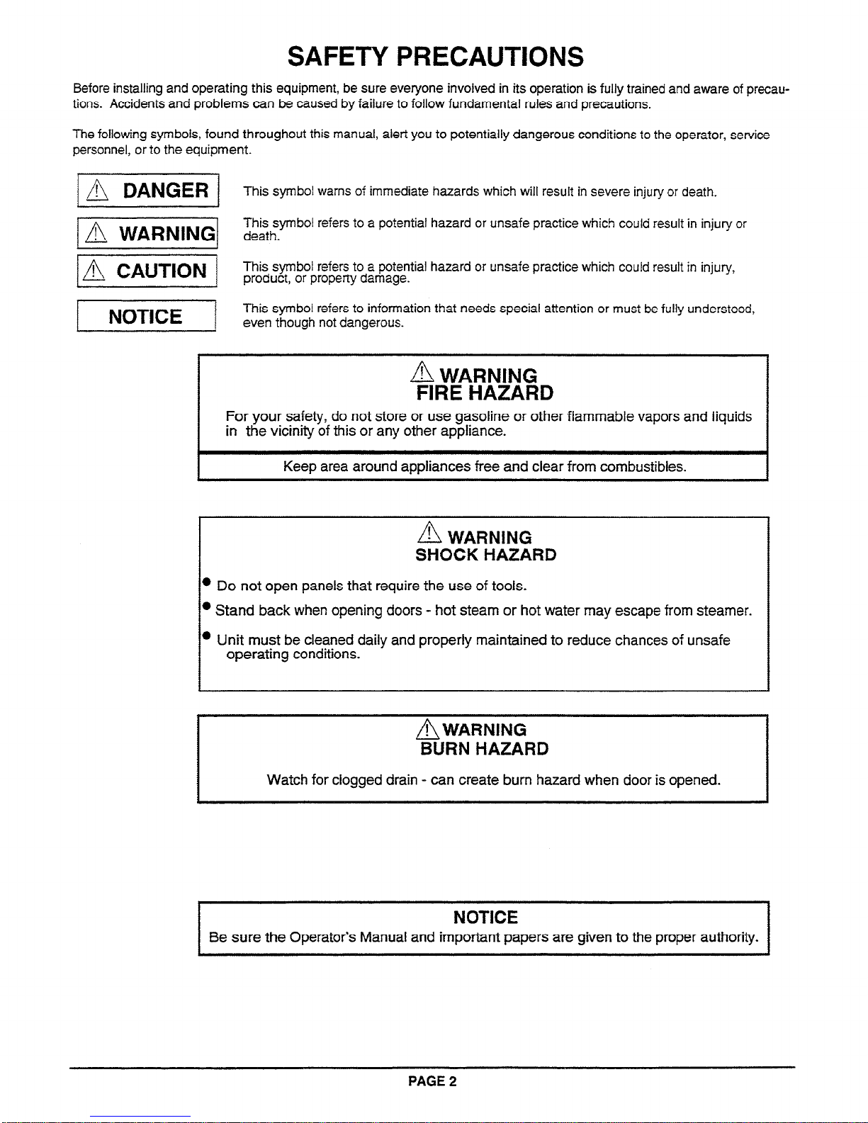
j A DANGER 1
This symbol warns of immediate hazards which will result in severe injury or death.
VI
This symbol refers to a potential hazard or unsafe practice which could result in injury or
death.
IA CAUTION /
This symbol refers to a potential hazard or unsafe practice which could result in injury,
product, or property damage.
This symbol refers to information that needs special attention or must be fully understood,
even though not dangerous.
L% WARNING
FIRE HAZARD
I
For your safety, do not store or use gasoline or other flammable vapors and liquids
in the vicinity of this or any other appliance.
Keep area around appliances free and clear from combustibles.
n
! WARNING
SHOCK HAZARD
l
Do not open panels that require the use of tools.
l
Stand back when opening doors - hot steam or hot water may escape from steamer.
l
Unit must be cleaned daily and properly maintained to reduce chances of unsafe
operating conditions.
A WARNING
BURN HAZARD
Watch for clogged drain - can create burn hazard when door is opened.
NOTICE
Be sure the Operator’s Manual and important papers are given to the proper authority.
PAGE 2
Page 4
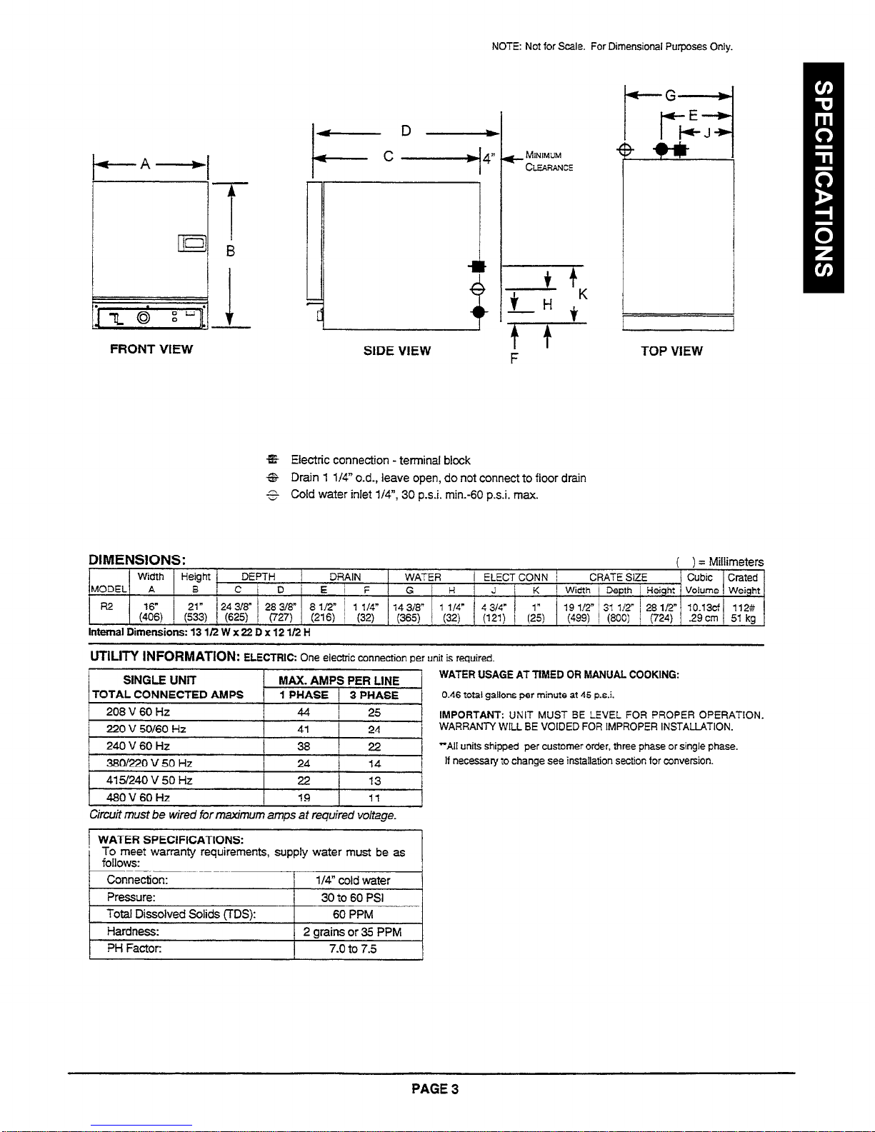
NOTE: Not for Scale. For Dimensional Purposes Only.
k-G-
FRONT VIEW
+-D-
-c
4
SIDE VIEW
rc- MINIMUM
CLEARANCE
F
TOP VIEW
%%
Electric connection - terminal block
6&
Drain 1 l/4” o.d., leave open, do not connect to floor drain
5
Cold water inlet l/4”, 30 p.s.i. min.-60 p.s.i. max.
DIMENSIONS:
( ) = Millimeters
Width
Height
DEPTH
DRAIN WATER / ELECTCONN /
CRATE SIZE
Cubic Crated
MODEL A
B C D
E i F
G
H J K
I Width 1 Depth 1
Height
Volume Weight
R2 - ”
$6,
(:;3) (625)
24318” 28318” 8 l/2* / 1 114”
14 318”
1 l/4” 4 314”
(727) (216) ! (32) (365)
(32)
(121)
(2)
19 l/2” ’ 31 i/2- ’ 28 l/2” 10.13cf
112::
(499) / (800) 1 (724) .29 cm 51 kg
Internal Dimensions: 13 11’2 W x 22 D x 12 l/2 H
UTILITY INFORMATION:
ELECTRIC: One electric connection per unit is required.
SINGLE UNiT
MAX. AMPS PER LINE
TOTAL CONNECTED
AMPS
1 PHASE / 3
PHASE
208 V 60 Hz
44 I
25
220 V 50160 Hz
41
24
240 V 60 Hz
38
22
3BOl220 V 50 Hz
24
14
1
4151240 V 50 Hz I 22 I 13 I
1 480V60Hz
19 11
J
Circuit must be wired for maximum amps at required voltage.
! WATER SPECIFICATIONS:
To meet warranty requirements, supply water must be as
follows:
Connection:
l/4”
cold water
Pressure: 30 to 60 PSI
Total Dissolved Solids TTDS):
60 PPM
1 Hardness:
1 2 arainsor35 PPM
1
1 PH Factor:
I
7.0 to 7.5
I
WATER USAGE AT TIMED OR MANUAL COOKING:
0.46 total gallons per minute at 45 p.s.i.
IMPORTANT:
UNIT MUST
BE LEVEL FOR PROPER OPERATION.
WARRANTY WILL BE VOIDED FOR IMPROPER INSTALLATION.
“Ail
units shipped per
customer order, three phase or single phase.
If necessary to change see installation section for conversion.
PAGE 3
Page 5
NOTICE
Floor drain must be located outside the confines of the equipment base.
Southbend reserves the right to change specifications and product design without notice. Such
revisions do not entitle the buyer to corresponding changes, improvements, additions, or replacements
for previously purchased equipment.
GENERAL:
The unit, when installed, must be electrically grounded and comply with local codes, or in the
absence of local codes with the National Electrical Code ANSIINFPA 704atest edition.
Canadian installation must comply with CSA-Standard (C22.2 No. log-Ml981 General
Requirements-Canadian Electrical Code, Part II. 109M1981) Commercial Cooking
Appliances.
NOTICE
These procedures must be followed by qualified personnel or warranty will be voided.
NOTICE
PAGE 4
Page 6
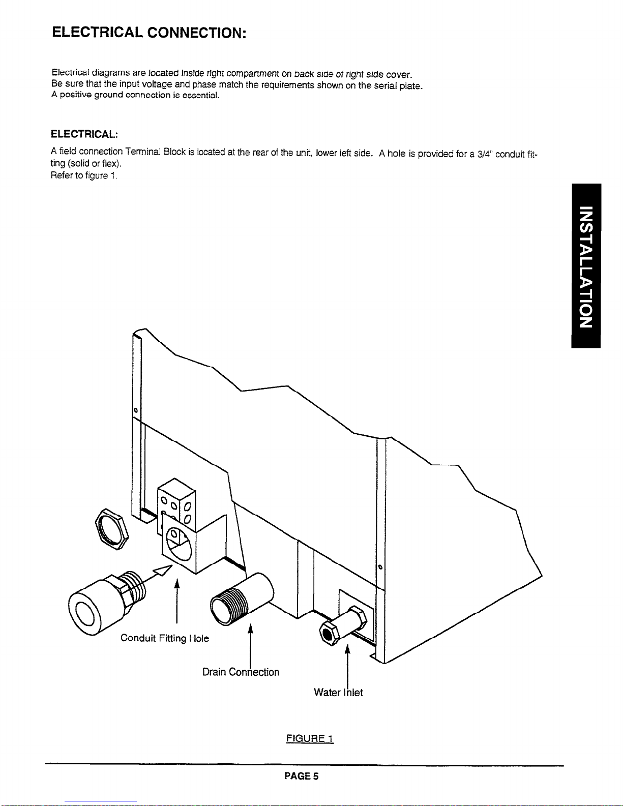
ELECTRICAL CONNECTION:
Electrical diagrams are located inside right compartment on back side of right side
cover.
Be sure that the input voltage and phase match the requirements shown on the serial plate.
A positive ground connection is essential.
ELECTRICAL:
A field connection Tem%nal Block is located at the rear of the unit, lower left side. A hole is provided for a 3/4” conduit fit-
ting (solid or flex).
Refer to figure 1.
Conduit Fitting Hole
Drain Conhection
I
Water Inlet
FIGURE 1
PAGE 5
Page 7

NOTE:
This unit has one power supply for controls and elements, as well as one ground wire. A POSITIVE GROUND
CONNECTION IS ESSENTIAL.
DO NOT ALLOW ANY TAMPERING OR ADJUSTMENT OF ANY CONTROL OR WIRING. THE UNIT IS FACTORY SET. ADJUSTMENT OF ANY INTERNAL COMPONENT OTHER THAN THE FIELD TERMINAL
BLOCK CAN VOID THE WARRANTY.
ELECTRICAL CONNECTION NOTE:
All 208-220-240 and 480 volt units will have three terminal block sections. “Ll-L2-L3.” for use with either 3-wire 3-phase or
2-wire, single-phase, 50 or 60 Hz.
Ail 380V and 415V units will have four terminal block sections, “Ll-L2-L3-N,” for use with European style 4-wire 3-phase
with neutral.
THREE PHASETO SINGLE PHASE CONNECTION:
Be sure that the input voltage matches the requirement on the serial plate. The unit is factory wired per customer order.
necessary to change phase, remove control panel, item “A” in figure 2, and rearrange element lead wires 2 and 3 as shown
below.
If
^, j__ ,._,,__,.:, ^ ~ .y-.y I
i’ i .:-
.‘.“‘%‘W”- I’;
,,“” .j :.. ..:.
I
I
I
208 - 220 - 240 - 48CV
INSIDE RIGHT SIDE O”EN!NG
WIRES CONTACTOR
5 1
32
64
~
Ll
L2
13
3-PHASE
WIRES CONTACTOR
/ 246-f~ @2
ARRANGE ELEMENT WIRES AS SHOWN
FIGURE 2
WATER CONNECTION:
Connect cold water line, l/4” (6mm) NPT into female side of strainer located at right lower side of unit as you face the
back of the steamer.
Water line pressure should be 30 psi (205 kpa) minimum to 60 psi (410 kpa) maximum.
I
I
NOTE: To facilitate cleaning, and allow access to rear of unit, flexible connections are recommended.
Recommended Plumbing:
(Furnished by Installer)
Do not connect steamer to a hot water hose. A hot water connection will damage the steamer.
I
COLD
WATER
SUPPLY
OFF
VALVE
REDUCING
VALVE IF
REQUIRED
b, WARNING
PAGE 6
VALVE
I
Page 8

WATER SPECIFICATION:
To meet warranty requirements,
Pressure:
Total
Dissolved Solids (TDS): 60 PPM
Hardness:
pH Factor:
supply water must meet the following specification:
30 to 60 psi
2 Grains or 35 PPM
7.0 to 7.5
DRAIN LINE:
The drain line connection size from the unit is 1” NPT (32 mm). Position the unit near, but not on top of, an open floor
drain. DO NOT directly plumb to the unit unless you also install an “open funnel” downstream of this connection in the
drain system. Make the drain line from the unit to the air gap above the “open funnel” as short as possible. There should
be no horizontal piping between the unit and the air gap above the “open funnel.” The “open funnel” is intended to eliminate any water from entering the steamer because of a blocked drain and it also prevents any back pressure within the
steamer cavity. The unit must be free-venting to the atmosphere. Any connection that allows the build-up of back pressure in the unit such as a reduction in pipe size to a line smaller than 1” or a 90 degree angle in the line prior to the
“open funnel” drain discharge point may cause personal or property damage and therefore will void the warranty. This is
a pressureless, free-venting steam cooker and will not operate properly unless the drain line is short, at a steep angle,
and open! See figure 3.
Side View
\
Stand
Pipe
Rear View
I
FIGURE 3
Air Gap
7
7y
+
Air Gap
7 ,I,
A WARNING
BURN HAZARD
It is imperative that the drain connection be installed per instructions and kept clean (open) to assure
free venting to atmosphere. A clogged drain will cause pressure to build up inside the steamer cavity
and can endanger the operator when opening the door. It will also cause excessive leakage of
steam from the door.
NOTICE
Floor drain must be located outside the confines of the equipment base or damage to equipment may
occur.
Do not locate unit adjacent to any high heat or grease producing piece of equipment, such as a range top, griddle,
fryer, etc., that could allow radiant heat to raise the exterior temperature of the steam body above 130°F (54°C).
DO NOT MOUNT ABOVE OTHER COOKING EQUIPMENT.
PAGE 7
Page 9

NOTICE
Local codes regarding installation vary greatly from one area to another. The National Fire
Protection Association, Inc. states in its NFPA 96 latest edition that local codes are “authority
having jurisdiction” when it comes to installation requirements for equipment. Therefore,
installations should comply with all local codes.
EXHAUST FANS AND CANOPIES:tt
hood. Consult local codes for proper installation of hoods.
is recommended that the steamer be installed under a ventilation
LEVELING:
Unit must be level to assure maximum performance. Improper leveling may void warranty.
NOTICE
Proper ventilation is the owner’s responsibility. Any problem due to improper ventilation will not
covered by warranty.
be
TO INSTALL:
1. Uncrate carefully. Report any hidden
damage to the freight carrier IMMEDIATELY.
2. Do not remove any tags or labels
until unit is installed and working
properly.
If unit is to be installed on legs, locate
3.
legs and install as shown on drawing.
(See Figure 4.)
cu
FIGURE
4
PAGE 8
Page 10

4.
If unit is to be installed on a counter top or other surface without using legs, the unit must be sealed to the surface
to prevent any water, grease, etc. from accumulating under the steamer. The steamer can be bolted to the
counter but will still have to be sealed. The installer may use G.E. or DOW CORNING RTV type sealant. (Consult
local code for exact requirements.) See figure 5.
Steamer
\
Bottom View
Sealer
FIGURE 5
PERFORMANCE CHECK:
The following items should be checked within the first 30 days of operation by a qualified service technician.
1. Check doors for proper alignment.
2.
Check door gaskets for wear and sealing ability.
Sea
I
nt
3. Check spray tubes or nozzles for cleanliness and/or leakage.
4. Check all gauges, timers, valves and switches for proper operation.
5. Visually check control compartment wiring for burned or loose connections.
6. Check electrical load on elements for proper wattage.
7. Be sure operators understand the importance of proper cleaning and maintenance.
PAGE 9
Page 11

THEORY OF OPERATION
Compared to other steam cookers with complicated boilers, the R2 is a very simple machine. immersion elements are
installed on the left side of the cavity and when water covers the elements, water starts to boil and turn to steam. There is
no pressure in this unit.
The SteamMaster R2 is designed to provide quick heat-up from a cold start.
All equipment must be installed correctly to ensure proper operation and reliable service. installation instructions must be
followed by a qualified technician.
Before you turn the unit on, be sure that you have: POWER to unit, WATER to unit, and an OPEN DRAIN.
CONTROL OPERATIONS
START UP:
1. Close the drain valve (turn lever to the run position.).
2. Turn power switch on. Unit will fill and begin heating. Unit will be up to operating temperature, ready to use, in
approximately ten (10) minutes. The “Ready’ light will light up when the unit is ready to use.
NORMAL OPERATION:
2. “Manual” -This unit runs full-power continuously.
NORMAL OPERATION:
REVIEW -
l
Use timer as desired, put in “Manual” position to disable buzzer. Timer has no impact on operation.
l
To conserve water and electticity during “slow” periods, shut unit off, do
not
open drain valve.
SHUTOFF:
Turn power switch “Off.” Turn the drain valve lever to ‘DRAIN”.
OPERATING INSTRUCTIONS:
1. De-Lime Indicator Light - The “De-Lime” indicator light will illuminate when the unit senses that the elements
need cleaning. Usually a thin layer of deposits are present when this occurs. When the light signaling the opera-
tor that cleaning/de-liming should be performed, see “Maintenance, Periodic Cleaning” under service section for
recommended procedures.
2. Cleaning must be performed to restore normal operation of the unit. When the “DE-LIME” light comes on, the
contactor shuts off power to the elements.
A WARNING
BURN HAZARD
When door is being opened, hot steam or hot water may escape from steamer.
Stand back when
opening door.
PAGE 10
Page 12

SUGGESTED COOKING TIMES:
Timer settings are for general guidance only. Differences in food quality, size, shape, freshness, load size and degree of
doneness desired must be considered and adjustments made in time if necessary.
PRODUCT
Asparagus
Fresh
Frozen Spears
(Thawed) 5 Ibs. 20 (4 oz.)
Beans
Green - Frozen,
Green - Fresh
Wax - Frozen
Lima - Frozen
Cut 5 Ibs. 20 (4 oz.)
Broccoli
Spears - Fresh
Spears - Frozen
(Thawed) 5 Ibs. 20 (4 oz.)
Brussel Sprouts
Fresh
Fresh
Carrots
Frozen - Whole
Fresh - ‘/4 -inch
Baby
Bias Cut
Cabbage
Green, Cut Into Wedges
Red, Cut Into Wedges
WEIGHT
3% lbs.
5 Ibs. 20 (4 oz.)
5 Ibs. 20 (4 oz.)
5 Ibs. 20 (4 oz.)
4 Ibs. 16 (4 oz.)
5 Ibs. 20 (4 oz.)
5 Ibs. 20 (4 oz.)
5 lbs. 20 (4 oz.)
5 Ibs. 20 (4 oz.)
PORTIONS
14 (4 oz.)
24
16
COOKING TIME
(Minutes)
8-10
9 Full/Perforated
12 Full/Perforated
15-17 Full/Perforated
13 Full/Perforated
10 Full/Perforated
16-12 Full/Perforated
8 Full/Perforated
15-17 Full/Perforated
13 Full/Perforated
12 Full/Perforated
12 Full/Perforated
15 Full/Perforated
18-20 Full/Perforated
PAN USED
Full/Perforated
Cauliflower
Fresh, Whole
Fresh, Whole
Frozen, Flowerettes
Corn
Fresh, Cob, 4-5
Frozen -Whole
Frozen - Cob, 6
Inch Ears
Kernel
Inch Ears
Mixed Vegetables
Frozen
Peas
Frozen
Potatoes
Red Bliss - Whole
Russet& - Whole
Russetts - Peeled
Russet% l-Inch Cubes
Spinach
Fresh, Leaf
Frozen, Chopped
Zucchini
Fresh - Slices ‘/.,-Inch Thick
2 Ibs.
2 Ibs. 12 oz. 11 (4 oz.)
5 Ibs.
5% Ibs.
5 Ibs.
9 Ibs.
5 Ibs.
5 Ibs.
7 Ibs.
8 Ibs.
5 Ibs.
5 Ibs.
2% Ibs.
6 Ibs.
5 Ibs.
8 (4 oz.)
20 (4 oz.) 10-12
15
20 (4 oz.)
14
20 (4 oz.) 12 FulVPerforated
20 (4 oz.)
28
20
12
20 (4 oz.)
10 (4 oz.)
24 (4 oz.)
20 (4 oz.)
g-10 Full/Perforated
15 Full/Perforated
Full/Perforated
13-15 Full/Perforated
8 Full/Perforated
12-14 Full/Perforated
8 Full/Perforated
35 Full/Perforated
23-25 FulVPerforated
20 Full/Perforated
17 Full/Perforated
5 Full/Perforated
35 Full/Perforated
6-8 Full/Perforated
Eggs
Large - Hard Cooked
12 Ibs. 12
PAGE 11
15-16 ‘I2 Perforated
Page 13

COOKING TIME
PRODUCT
WEIGHT
PORTIONS
(Minutes)
Meats
Corned Beef
Hot Dogs, Thawed
Hot Dogs, Frozen
6% Ibs. 18 (6 oz.)
5 Ibs. 40 (2 oz.)
5 Ibs. 40 (2 oz.)
2 hours
10
Fowl
Boneless Chicken Breast
Tamales, Frozen
Tortilla, Frozen 8-Inch
Beef Ravioli, Frozen
4’12 Ibs.
3 Ibs. 12 (4 oz.)
4 Tortillas 4
48 Ravioli
12 (6 oz.)
8 5-6
15
20
45 Seconds
(1 lb. 8 oz.)
Elbow Macaroni 2 Ibs. 32 (2 oz.) 7
Uncooked
Spaghetti
2 Ibs.
32 (2 oz.)
14
Uncooked
Egg Noodles
2 tbs.
32 (2 oz.)
10
Uncooked
Converted Rice 2 Ibs.
25 Full/Perforated
2% Qts. Water
+ Oil 8 Salt
Navy Beans
2 Ibs.
Place beans in pan and cover with 3-quarts hot tap water.
Steam for 2 minutes; remove from steamer and cover for 1 hour.
Remove cover and place back in steamer for 40 minutes.
Black Eyed Peas
2 Ibs.
Place peas in pan and cover with 3quart.s hot tap water.
Steam for 2 minutes: remove from steamer and cover for 1 hour.
Remove cover and place back in steamer for 35 minutes.
5
PAN USED
Full
Full/Perforated
Full/Perforated
Full/Perforated
Full/Perforated
Half/Perforated
Full/Perforated
In Perforated Pan
Nested in Solid Pan
In 4-Inch
Full/Perforated
Full/Perforated
Full/Perforated
Full/Perforated
Seafood
Oysters
5 Ibs.
16 Count 12
Perforated
Pan Nested
in a Full Pan
2’hlnch Deep
Shrimp, Fresh, Medium,
5 Ibs.
6-7
Full/Perforated
Heads Removed
Shrimp, Frozen, Large,
5 lbs.
8
Full/Perforated
Peeled & Deveined
Lobster
Alaskan King Crab Legs
Cherrystone Clams
Fish Fillets
13/, Ibs.
1 lb.
5 lbs.
7’1, lb-s.
12
12 (10 oz.)
8
4-5
7
18
Full/Perforated
Full/Perforated
Full/Perforated
Full/Perforated
Nested in Full
Hotel Pan
END USER TIPS:
Schedule cooking of fresh vegetables so that they will be served socn after they are cooked. If it is necessary to prepare
them in advance, they can be plunged into cold water, drained thoroughly and held under refrigeration until needed for
service.
Five pounds of cold cooked vegetables can be reheated in the steamer in 5 to 10 minutes, depending upon the variety.
PAGE 12
Page 14

Adding salt to the water for eggs cooked in the shell makes the cooking water more efficient and faster at its job. If the egg
cracks, the white is cooked at the crack and is sealed right away.
To avoid green yolk (which is a deposit of iron sulfide) chill the eggs immediately after removing from the steamer by
plunging them into a cold water bath (preferably containing ice).
A quick and easy way to cook eggs for a salad mixture is to crack them directly into a solid steam table pan which has
been lightly coated with salad oil. Do not mix. Steam until they are hard cooked. Remove and chop as you would for egg
salad. The job of peeling has been eliminated.
Transfer steamed hot chicken to deep pan, cover with Cacciatore Sauce and finish in oven. Bake 20 to 30 minutes. May
be held on steam table.
After steaming, chicken, sausage, and fish may be browned in infra-Red or Radiant Broiler. Brush with melted margarine
mixed with salad oil to give a golden brown color.
Use juice saved from steamed chicken or turkey to make soups, sauces, or casserole dishes.
Chicken may be steamed in advance and held under refrigeration for next day’s use. Be sure to bring product back to
180°F before serving.
Save the juice from the corned beef. After the cabbage has been steamed, place it in a solid pan and add the juice for flavoring and holding on a steam table.
Steaming brisket is a definite time saver. Boiling in water takes 40 to 50 minutes per pound. Using the R2 can save 50% in
cooking time.
Cabbage, when steamed, retains its color and wedge identity. It will not break apart as it does when boiled in an open pot.
When removing items prepared in a perforated pan, put a solid pan underneath the perforated pan to hold the pan of
cooked food. This will prevent dripping on the floor.
The R2 is designed to accept standard 12 x 20 pans. Fractional size pans and dishes can be used as weli with the optional
perforated shelf.
For stirring, the pan does not have to be removed from the steamer. Pull pan l/3 way out of the cavity and the entire sur-
face is accessible.
The door may be opened at any time during operation to remove or add food.
PAGE 13
Page 15

MAINTENANCE
Southbend equipment is sturdily constructed of the best quality materials and is designed to provide durable service when
treated with ordinary care. To expect the best performance, your equipment must be maintained in good condition and
cleaned daily. Naturally, the periods for this care and cleaning depend on the amount and degree of usage.
Following daily and periodic maintenance procedures will increase the life of your equipment. Cilmatic conditions - salt air seasonings - water quality - may require more thorough and frequent cleaning or the life of the equipment could be
adversely affected.
DAILY CLEANING
YOUR R2 MUST BE THOROUGHLY CLEANED EVERYDAY.
l
Remove the pan supports and well cover. Wash separately in a sink with a mild detergent and warm water. Dry thor-
oughly with a clean cloth. Scotch Brite scouring, pads may be used for baked-on deposits.
l
Wash interior surfaces, including the heating elements with a mild detergent and warm water. Rinse with clean water.
Dry thoroughly with a clean cloth. if discoloration starts due to build up of seasonings or food products, remove by using
Scotch-Brite scouring pad. Then wash, rinse, and dry as above.
l
Wash floats carefully, check that float stems are clean and floats move freely.
l
Wrpe exterior surface with a clean damp cloth.
l
Return all cleaned parts to the unit, placing in their proper position.
l
LEAVE THE DOOR OPEN AT NIGHT AFTER CLEANING. This allows the unit to dry thoroughly after cleaning and also
proiongs the life of the door gasket.
PERIODIC CLEANING - AS REQUIRED:
If a lime or mineral deposit starts to build up in the interior, this should be cleaned by using Southbend “descale? or other
non-caustic deiiming solution. Follow manufacturers recommended procedures. Thoroughly rinse out unit.
To remove food build up or discoloration, apply cleanser to a damp cloth or sponge and rub cleanser on the material in the
direction of the polishing lines on the metal. Never rub with a circular motion. Soil and discoloration which do not respond to
the above procedure can usually be removed by rubbing the surface with Scotch-Brite scouring pads.
DO NOT GET WATER IN THE CONTROLS.
Could
result in expensive repairs or electrical shock.
DO NOT USE ordinary steel wool as any particles left on the surface will rust. NEVER USE a wire brush, steel or abrasive
scouring pads, scraper, file or other steel tools. Surfaces which are marred collect dirt more rapidly and become more difficult to clean. Marring also increases the possibility of corrosive attack.
DO NOT clean door gasket with a high chlorine solution or bleach.
NEVER USE A CORROSIVE CLEANER. USE ONLY CLEANERS APPROVED FOR STAINLESS STEEL.
STAINLESS STEEL:
To remove normal dirt, grease, or product residue from stainless steel, use ordinary soap and
water (with or without detergent) applied with a sponge or cloth. Dry thoroughly with a clean cloth. Never use vinegar or
any corrosive cleaner.
To remove grease and food splatter or condensed vapors that have baked on the equipment, apply cleanser to a damp
cloth or sponge and rub cleanser on the metal in the direction of the polishing lines on the metal. Rubbing cleanser as gently as possible in the direction of the polished iines will not mar the finish of the stainless steel. NEVER RUB WITH A CIR-
CULAR MOTION. Soil and burnt deposits which do not respond to the above procedure can usually be removed by rubbing the surface with SCOTCH-BRITE scouring pads. DO NOT USE ORDINARY STEEL WOOL, as any particles left on
the surface will rust and further spoil the appearance of the finish. NEVER USE A WIRE BRUSH, STEEL SCOURING
PAD, SCRAPER, FILE OR OTHER STEEL TOOLS. Surfaces which are marred collect dirt more rapidly and become
more difficult to clean. Marring also increases the possibility of corrosive attack. Refinishing may then be required.
PAGE 14
Page 16

MAINTENANCE
A WARNING
BURNHAZARD
~ For proper and safe operation, this steamer must be cleaned daily.
Be sure the overflow pipe is not clogged before operating. A clogged pipe could cause too much hot
water to enter the steamer thereby creating a BURN HAZARD when the door is being opened. Clean
this steamer daily as described in this manual. Failure to do so could result in serious injury or damage.
Drains must be kept clean and clear of debris.
A WARNING
SHOCK HAZARD
De-energize all power to equipment before cleaning the equipment.
A CAUTION
DO NOT USE ordinary steel wool as any particles left on the surface will rust.
NEVER USE a wirebrush, steel or abrasive scouring pad, scraper, file or other steel tools.
Surfaces which are marred collect dirt more rapidly and become more difficult to clean.
Marring also
increases the possibility of corrosive attack.
DO NOT clean door gasket with a high chlorine solution or bleach.
NEVER use any corrosive cleaner. Use only cleaners approved for stainless steel.
A WARNING
I
Improper cleaning can result in expensive repairs or electrical shock. Do not get water on electrical
controls or motors.
I
PAGE 15
Page 17

ADJUSTMENTS
NOTICE
Service work should be performed only by a qualified technician who is experienced in, and
knowledgeable of, the operation of commercial gas, electric, and steam cooking equipment.
Contact the Authorized Service Agency for reliable service, dependable advice or other
assistance, and for genuine factory parts.
Warranty will be void and the manufacturer is relieved of all liability if:
(A) Service work is performed by other than a qualified technician.
(6) Other than genuine Southbeni?eplacement parts are installed.
TFiOlJBLE SHOOTING GUIDE
Symptom:
Check of Replace:
No power
No water
Check circuit breaker
Check water supply
Heating elements will only operate for brief
regular cycles and delime light is illuminated.
Clean
and delime
steamer
SHOCK HAZARD
De-energize all power to equipment before servicing the equipment.
At least twice a year, have your Southbend Authorized Service Agency or another qualified service technician
clean and adjust the unit for maximum performance.
Consult the Southbend Authorized Parts/Service Distributor list for the Authorized Service Representative in your
area. If this
is not
available, call the Service Department at Southbend, l-800-348-2558 for their name and num-
ber.
PAGE 16
Page 18

PARTS -- ACCESSORIES
Genuine Pms
Pmlecr YOU ALL-Ways!
NOTICE
INSTALLATION OF OTHER THAN GENUINE SOUTHBEND PARTS WILL VOID THE
WARRANTY ON THIS EQUIPMENT.
The serial plate with voltage, model, and serial information is located on the right side of the steamer cavity on the
upper rear comer. On single units a second tag is located on the face of the door which will show only model and serial number. On Tandem units, a second tag is on the right side of the right unit and the left side of the left unit.
Replacement parts may be ordered either through a Southbend Authorized Parts Distributor or a Southbend
Authorized Service Agency.
When ordering parts, please supply the Model Number, Serial Number, Part Number, Description, Finish, and
Electrical Characteristics as applicable.
For parts not listed, consult a Southbend Authorized Pans Distributor or Southbend Authorized Service Agency.
Consult the Southbend Authorized Parts/Service Distributor list for the Authorized Parts supplier in your area. If this
list is not available, call the Service Department at Southbend, l-800-348-2558 for same.
/ ITEM
B 1173195
............................. .....................................................................................................................................................................................
C 1177072 Door Gasket
............................. .....................................................................................................................................................................................
D 1174587 Cavity, Side Rack
............................ .....................................................................................................................................................................................
E 1178268 Well Cover Deflector
............................. ......................................................................................................................................................................................
F 1177080 Door Striker
............................ .....................................................................................................................................................................................
l
............................ ......................................................................................................................................................................................
l
............................ ......................................................................................................................................................................................
l
............................. .....................................................................................................................................................................................
*
.................................................................................................................................................................................................................
l
L
1 PART NO.
4460002 Technical Manual
1176561 Cleaning Instructions
PM-162 Cleaning Pad
4450020 SteamMaster descaler 24 pack
4450021 SteamMaster Descaier Master Pack (Contains 8 of the 4450020)
FIGURE 6
DESCRIPTION
Retainer Panel Assembly
]
PAGE 17
Page 19

No
QUIB~RRANTY
m If a customer calls with a problem involving any Southbend product, we will rectify it,
a day, 7 days a week, 365 days a year.
m 0ur”No Quibble” Warranty means there will be no charge to the customer for the call, parts, travel or for
premium time. If the problem turns out that the unit is unplugged, the circuit breaker is tripped, the gas is
shut off, or even if the customer doesn’t know how to operate the equipment, etc.,-it’s covered.
no charge:
24 hours
, ._ :a
The foregoing warranty is exclusive and in lieu of all other warrant&S,
expressed or implied. There are no
implied
warranties of merchantab&ty
‘;
or of fitness for a particular purpose.
I;i Southbend, hereinafter referred to as the seller, warrants equipment manufactured by it to be free from
defects in material and workmanship for which it is responsible. The sellers obligation underthis warranty shall be limited to replacing or repairing such part. Such warranty shall be limited to the original purchaser only and shall be effective for a period of one year from date of original installation or 18 months
from date of purchase, whichever is earlier; provided that the terms of payment have been fully met.
m Normal maintenance functions, including lubrication, cleaning or customer abuse are not covered by this
No Quibble Warranty.
Il;ii The seller shall be responsible only for repairs or replacements of defective parts performed by seller’s
authorized service personnel. Authorized service agencies are located in principle cities throughout the
contiguous United States and Hawaii. This warranty is valid in the United States and is void elsewhere ._,, ,,~ x,
unless the product is purchased through Middleby International with warrantyjnciuded .-I’- ” ““‘“:I ‘~““.“.“““*“.
m The foregoing shall be th,e.seilePs~soisarid ex&s& dbiigation and the buyer’s s&e and exciusive, ,,
remedy.for”any a&on including breach of contract or negligence.
,~~. ,...
a sum in excess of the purchase price of the item. The setter shall not be liable for any prospective or
lost profits of the buyer.
_.,.. ’
,, ~ .~. .~
,,, ._ “.
In,ng”.e~~~t..s~ail-t~e sellerbe iable for
“’ ,. ,,
” ,, ,
. ^
”
m This warranty is effective on Southbend equipment sold on, or after
PAGE
18
Feb. 15, 1996.
Page 20

SOUTHBEND
LIMITED WARRANTY
Southbend warrants that the equipment, as supplied by the factory to the original purchasers, is free from defects in materials
and workmanship. Should any part thereof become defective as a result of normal use within the period and
limits defined below, then at the option of Southbend such parts will be repaired or replaced by Southbend or its Authorized
Service Agency. This warranty is subject to the following conditions:
If upon inspection by Southbend or its Authorized Service Agency it is determined that this equipment has not been
used in an appropriate manner, has been modified, has not been properly maintained, or has been subject to misuse
or misapplication, neglect, abuse, accident, damage during transit or delivery, fire, flood, not or Act of God, then this warranty
shall be void.
Specifically excluded under this warranty are claims relating to installation; examples are improper utility connections
and improper utilities supply. Claims relating to normal care and maintenance are also excluded; examples are calibration of controls and adjustments to pilots and burners.
Equipment failure caused by inadequate water quality is not covered under warranty. WATER QUALITY must not exceed the following limits: Total Dissolved Solids (TDS) - 60 PPM (Parts Per Million). Hardness
- 2 Grains or 35 PPM, PH Factor - 7.0 to 7.5.
Water pressure 30 PSI minimum, 60 PSI maximum. Boiler maintenance is the responsibility of the owner
and is not covered by warranty.
This equipment is intended for commercial use only. Warranty is void if equipment is installed in other than commercial application.
Repairs under this warranty are to be performed only by a Southbend Authorized Service Agency. Southbend cannot
be responsible for charges incurred from other than Authorized Southbend Agencies.
THIS WARRANTY MUST BE SHOWN TO AN AUTHORIZED SERVICE AGENCY WHEN REQUESTING IN-WARRANTY SER-
VICE WORK. THE AUTHORIZED SERVICE AGENCY MAY AT HIS OPTION REQUIRE PROOF OF PURCHASE.
This warranty does not cover services performed at overtime or premium labor rates nor does Southbend assume any liability for
extended delays in replacing or repairing any items in the equipment beyond the control of Southbend. “Southbend shall not be
liable for consequential or special damages of any nature that may arise in connection with such product or part.” Should service
be required at times which normally involve overtime or premium labor rates, the owner shall be charged for the difference
between normal service rates and such premium rates.
In all circumstances, a maximum of one hundred miles in travel and two and one half hours (2.5) travel time shall be allowable. In
all cases, the closest Southbend Authorized Agency must be used.
The actual warranty time periods and exceptions are as follows:
This warranty only covers product shipped into the 48 contiguous United States and Hawaii, one-year labor, one-year parts effec-
tive from the date of original purchase. There will be no labor coverage for equipment located on any island not connected by
roadway to the mainland.
Exceptions to standard warranty, effective within above limitations:
Glass Windows, Door Seals, Rubber Seals, Light Bulbs, Ceramic Bricks,
Sight Glasses, Cathodic Descalers or Anodes . . . . . . . . . . . _ . . . . . . . . . . _ . . . . . . . _. . . . . . . . . . . . . . . . _. . . . . . . . _ . _ _ _ _ 90 days material and labor
Stainless Steel Fry Pot
. . . . . . . . . _. . . . . . . . . . _ . . . . . . . . . . . . . _ _ . . . _ . . _. . . .4 years extended material warranty on fry pot only - no labor
Stainless Steel Open Top Burners.. _ _. _ . . _ . . . . . . . . . . . . . . _. . . . . . . . .4 years extended material warranty on burners only - no labor
Pressure Steam Boiler Shell _ . . . . . . . . . _ _ . . . . . . . . . . _. . . . _. . _ . . . . Prorated 4 years extended warranty on boiler shell only - no labor
Boiler shells which have not been properly maintained will not be covered by warranty.
In all cases, parts covered by a five-year warranty will be shipped FOB the factory after the first year.
Our warranty on all replacement parts which are replaced in the field by our Authorized Service Agencies will be limited to
three months on labor, six months on materials (parts) effective from the date of installation. See LIMITED WARRANTY -
REPLACEMENT PARTS for conditions and limitations.
If the equipment has been changed, altered, modified or repaired by other than a qualified service technician during
or after the one-year limited warranty period, then the manufacturer shall not be liable for any damages to any person or to
any property which may result from the use of the equipment thereafter.
‘THE FOREGOING WARRANTY IS IN LIEU OF ANY AND ALL OTHER WARRANTIES EXPRESSED OR IMPLIED INCLUD-
ING ANY IMPLIED WARRANTY OF MERCHANTABILITY OR FITNESS, AND CONSTITUTES THE ENTIRE LIABILITY OF
SOUTHBEND. IN NO EVENT DOES THE LIMITED WRRANTY EXTEND BEYOND THE DURATION OF ONE YEAR FROM
THE EFFECTIVE DATE OF SAID “WARRANTY.”
Consult the Southbend Authorized Parts/Service Distributor list for the Authorized Service Representative in your area.
If this list is not available, call the Service Department at Southbend, 1-800-348-2558.
Page 21

A MIDDLEBY COMPANY
SOUTHSEND
Cwtfication NO. FM25780
REGISTERED TO IS0 9001
CERTIFICATE NO. A.2062
Southbend Registered to IS0 9001
A product with the Southbend name incorporates the best in durability
and low maintenance. We all recognize however, that replacement parts
and occasional professional service may be necessary to extend the
useful iife of this unit. When service is needed, contact a Southbend
Authorized Service Agency, or your dealer. To avoid confusion; always
refer to the model number, serial number, and type of your unit.
Southbend
1100 Old Honeycutt Road
Fuquay-Varina, NC 27526
(800) 348-2558 - (919) 552-9161
FAX (800) 348-2558 . (919) 552-8682
httpz//www.middleby.com
PART NUMBER 1177893
PRINTED W98
0 1998 SOUTHBEND
 Loading...