

Page 1
IMPORTANT FOR FUTURE REFERENCE
Please complete this information and retain this
manual for the life of the equipment:
Model #: ___________________________
Serial #: ___________________________
Date Purchased: ____________________
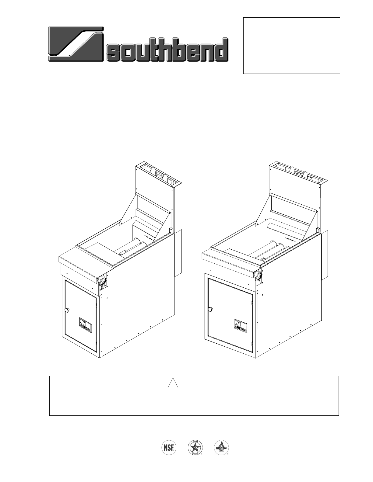
OPERATOR’S MANUAL
Model P16-FR45 and P20-FR65
Sectional Deep Fryer
Model P16-FR45 Model P20-FR65
! WARNING
Improper installation, adjustment, alteration, service or maintenance can cause property damage,
injury or death. Read the installation, operating and maintenance instructions thoroughly before
installing or servicing this equipment.
1100 Old Honeycutt Road, Fuquay-Varina, NC 27526
www.southbendnc.com
MANUAL 1182110 REV 1
$18.00
SECTIONAL
MANUAL
DEEP FRYER
SECTION SR
Page 2
SECTIONAL DEEP FRYER
SAFETY PRECAUTIONS
Before installing and operating this equipment, be sure everyone involved in its operation is fully trained and
aware of precautions. Accidents and problems can be caused by failure to follow fundamental rules and
precautions.
The following symbols, found throughout this manual, alert you to potentially dangerous conditions to the
operator, service personnel, or to the equipment.
! DANGER
! WARNING
! CAUTION
NOTICE
This symbol warns of immediate hazards that will result in severe injury or
death.
This symbol refers to a potential hazard or unsafe practice that could result in
injury or death.
This symbol refers to a potential hazard or unsafe practice that could result in
injury, product damage, or property damage.
This symbol refers to information that needs special attention or must be fully
understood, even though not dangerous.
! WARNING
FIRE HAZARD
FOR YOUR SAFETY
Do not store or use gasoline or other flammable vapors and liquids in the vicinity of this or any other
appliance.
Keep area around appliances free and clear of combustibles.
Purchaser of equipment must post in a prominent location, detailed instructions to be followed in the
event the operator smells gas. Obtain the instructions from the local gas supplier.
! WARNING
BURN HAZARD
Contact with hot oil will cause severe burns. Always use caution. Oil at 200°F is more dangerous than
boiling water.
! WARNING
In the event a gas odor is detected, shut down equipment at the combination gas valve and contact
the local gas company or gas supplier for service.
NOTICE
Southbend Sectional Deep Fryers are intended for commercial use only. Not for household use.
Warranty will be void if service work is performed by other than a qualified technician, or if other than
genuine Southbend replacement parts are installed.
Be sure this Operator’s Manual and important papers are given to the proper authority to retain for
future reference.
PAGE 2 OPERATOR’S MANUAL 1182110 REV 1
Page 3

SECTIONAL DEEP FRYER TABLE OF CONTENTS
Congratulations! You have purchased one of the finest pieces of heavy-duty commercial cooking equipment
on the market.
You will find that your new equipment, like all Southbend equipment, has been designed and manufactured
to meet the toughest standards in the industry. Each piece of Southbend equipment is carefully engineered
and designs are verified through laboratory tests and field installations. With proper care and field
maintenance, you will experience years of reliable, trouble-free operation. For best results, read this
manual carefully.
RETAIN THIS MANUAL FOR FUTURE REFERENCE.
MODEL NUMBERS
This manual is for the Southbend Sectional Deep Fryer models P16-FR45 and P20-FR65, which can be
ordered with a front-to-back depth of 36" or 42". The serial plate is located inside the front door on the left
side.
Table of Contents
Specifications .........................................................................................................................4
Installation ..............................................................................................................................7
Operation..............................................................................................................................14
Cooking Hints .......................................................................................................................17
Cleaning ...............................................................................................................................19
Service.................................................................................................................................. 22
Parts .....................................................................................................................................27
Read these instructions carefully before attempting installation. Installation and initial startup should be
performed by a qualified installer. Unless the installation instructions for this product are followed by a
qualified service technician (a person experienced in and knowledgeable with the installation of commercial
gas an/or electric cooking equipment) then the terms and conditions on the Manufacturer’s Limited Warranty
will be rendered void and no warranty of any kind shall apply.
In the event you have questions concerning the installation, use, care, or service of the product, write to:
Southbend
1100 Old Honeycutt Road
Fuquay-Varina, North Carolina 27526 USA
OPERATOR’S MANUAL 1182110 REV 1 PAGE 3
Page 4
SPECIFICATIONS SECTIONAL DEEP FRYER
A
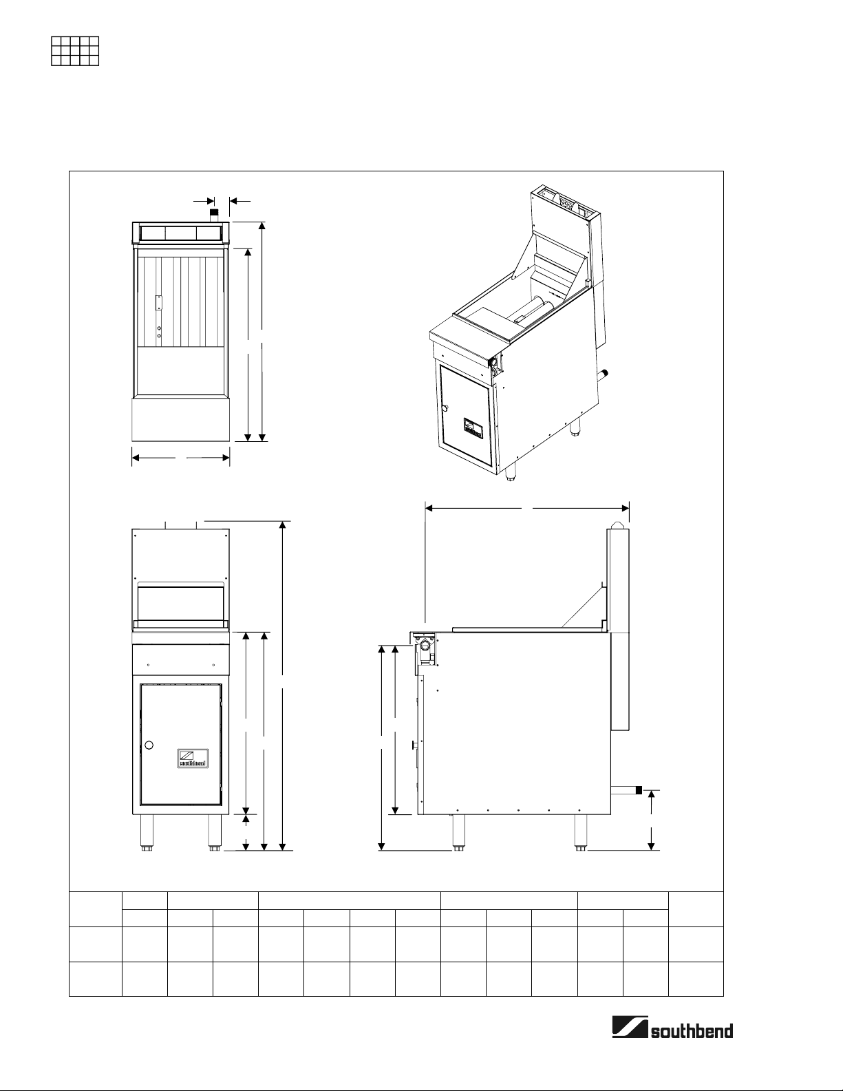
SPECIFICATIONS
DIMENSIONS OF MODEL P16-FR45
SPECIFICATIONS
L
C
B
Depth
Option
36"
42"
Top View
J
G
36.0"
(914)
36.0"
(914)
I
H
K
Side View
54.0"
(1372)
54.0"
(1372)
33.8
(859)
33.8
(859)
27.8
(706)
27.8
(706)
33.5
(851)
39.5
(1003)
9.5"
(241)
9.5"
(241)
2.0"
(51)
2.0"
(51)
E
F
D
Front View
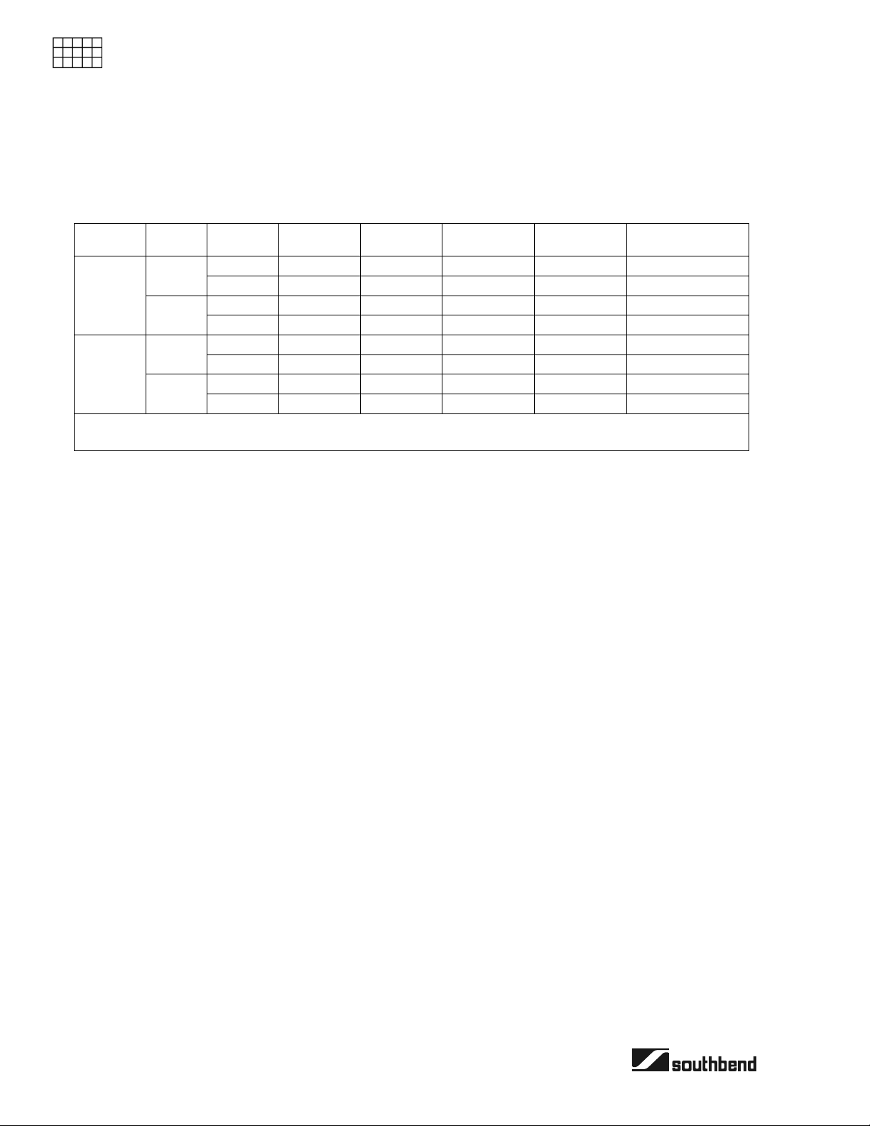
Width Depth Height Front Gas Connection Rear Gas Conn.
A B C D E F G H I J K L
16.0"
(406)
16.0"
(406)
31.8
(808)
37.8
(960)
36.0"
(914)
42.0"
(1067)
6.0"
(152)
6.0"
(152)
30.0"
(762)
30.0"
(762)
Crated
Weight
219 lbs
99 kg
222 lbs
101 kg
PAGE 4 OPERATOR’S MANUAL 1182110 REV 1
Page 5
SECTIONAL DEEP FRYER SPECIFICATIONS
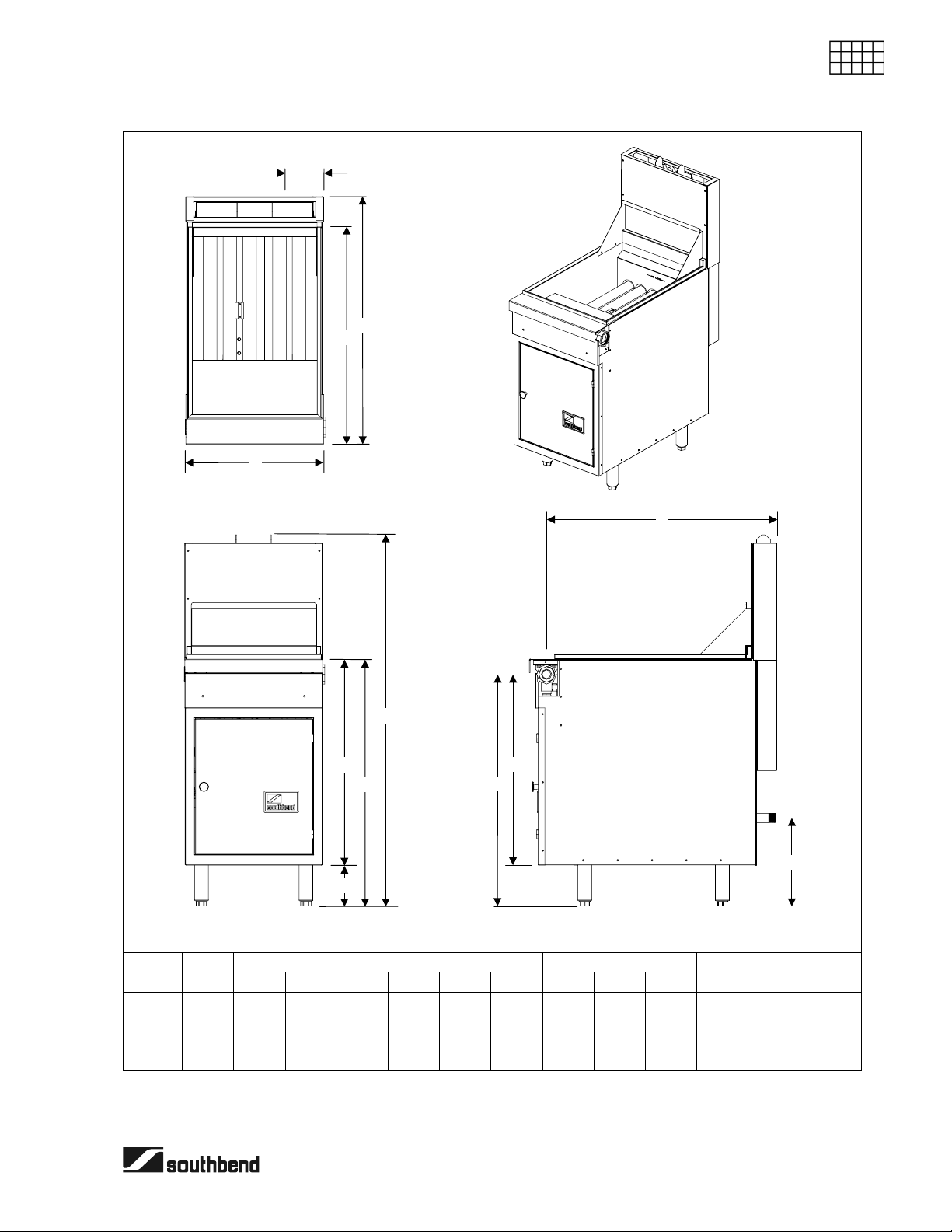
A
DIMENSIONS OF MODEL P20-FR65
L
C
B
Top View
SPECIFICATIONS
Depth
Option
36"
42"
J
G
H
54.0"
(1372)
54.0"
(1372)
I
Side View
33.8
(859)
33.8
(859)
27.8
(706)
27.8
(706)
33.5
(851)
39.5
(1003)
12.8"
(325)
12.8"
(325)
4.5"
(114)
4.5"
(114)
E
F
D
Front View
Width Depth Height Front Gas Connection Rear Gas Conn.
A B C D E F G H I J K L
20.0"
(508)
20.0"
(508)
31.8
(808)
37.8
(960)
36.0"
(914)
42.0"
(1067)
6.0"
(152)
6.0"
(152)
30.0"
(762)
30.0"
(762)
36.0"
(914)
36.0"
(914)
K
Crated
Weight
229 lbs
104 kg
232 lbs
105 kg
OPERATOR’S MANUAL 1182110 REV 1 PAGE 5
Page 6
SPECIFICATIONS SECTIONAL DEEP FRYER
GAS SUPPLY AND BURNER INFORMATION
Supply pressure should be greater than 7" W.C. for natural gas or greater than 11" W.C. for propane. The
fryer has an internal, field-convertible gas-pressure regulator. The front manifold has a 1-1/4" connector on
each end (the end on the left side of the fryer is male, while the end on the right side of the fryer is female).
If the fryer has the optional rear gas connection, it has a 1" NPT male connector located on back (see
SPECIFICATIONS
illustrations on pages 4, 5, and 8).
Model Burners Gas Type
Main
P16-FR45
Pilot
Main
P20-FR65
Pilot
* Minimum supply pressure is 7" W.C. for natural gas and 11" W.C. for propane.
** Orifice sizes are for units installed at altitudes between 0 and 2000 feet above sea level.
Natural 4" W.C. 4 35,000 140,000 #36 - 0.1065" dia.
Propane 10" W.C. 4 30,000 120,000 #52 - 0.0635" dia.
Natural 4" W.C. 1 900 900 #77 - 0.0180" dia.
Propane 10" W.C. 1 900 900 0.0110" dia.
Natural 4" W.C. 5 35,000 175,000 #38 - 0.1015" dia.
Propane 10" W.C. 5 30,000 150,000 #52 - 0.0635" dia.
Natural 4" W.C. 1 900 900 #77 - 0.0180" dia.
Propane 10" W.C. 1 900 900 0.0110" dia.
Manifold
Pressure*
Number
per Unit
ELECTRICAL REQUIREMENT
No external electric power is required.
CLEARANCES
See page 12.
Rate Each
BTUs/Hour
Total Rate
BTUs/Hour
Orifice Size
PAGE 6 OPERATOR’S MANUAL 1182110 REV 1
Page 7
SECTIONAL DEEP FRYER INSTALLATION
INSTALLATION
NOTICE
Installation must conform with local codes, or in the absence of local codes, with the National Fuel
Gas Code, ANSI Z223.1, Natural Gas Installation Code, CAN/CGA-B149.1, or the Propane
Installation Code, CAN/CGA-B149.2, as applicable.
NOTICE
These installation procedures must be followed by qualified personnel or warranty will be void.
Local codes regarding installation vary greatly from one area to another. The National Fire Protection
Association, Inc. states in its NFPA 96 latest edition that local codes are the “authority having
jurisdiction” when it comes to installation requirements for equipment.
INSTALLATION
Step 1: Unpack
IMMEDIATELY INSPECT FOR SHIPPING DAMAGE
All containers should be examined for damage before and during unloading. The freight carrier has
assumed responsibility for safe transit and delivery. If damaged equipment is received, either
apparent or concealed, a claim must be made with the delivering carrier.
Apparent damage or loss must be noted on the freight bill at the time of delivery. The freight bill must
then be signed by the carrier representative (Driver). If the bill is not signed, the carrier may refuse
the claim. The carrier can supply the necessary forms.
A request for inspection must be made to the carrier within 15 days if there is concealed damage or
loss that is not apparent until after the equipment is uncrated. The carrier should arrange an
inspection. Be certain to hold all contents plus all packing material.
1. Uncrate carefully. Report any hidden damage to the freight carrier IMMEDIATELY.
2. Do not remove any tags or labels until unit is installed and working properly.
OPERATOR’S MANUAL 1182110 REV 1 PAGE 7
Page 8
INSTALLATION SECTIONAL DEEP FRYER
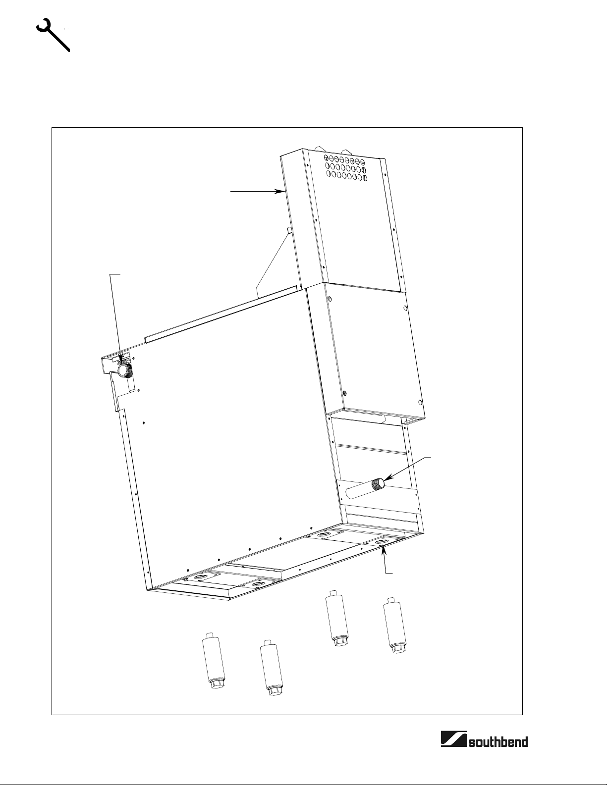
Step 2: Install Flue Riser
The flue riser assembly is packed separately in the shipping crate. Attach the flue riser to the top rear of the
fryer as shown in the illustration below.
Flue Riser
INSTALLATION
Front Gas
Manifold
Connection
(both sides)
Optional
Rear Gas
Connection
Leg Attachment Pad
PAGE 8 OPERATOR’S MANUAL 1182110 REV 1
Page 9
SECTIONAL DEEP FRYER INSTALLATION
Step 3: Install the Legs (or Casters) and Restraint
A set of legs or casters is packed with the fryer. A threaded pad is fastened to the base frame at each corner
(see illustration on page 8). Each leg or caster has a similar mating thread. When casters have been
ordered, the casters are provided with a Zerk fitting for proper lubrication when required.
1. Raise fryer sufficiently to allow legs or casters to be screwed into the pads. For safety, “shore up” and
support the fryer with an adequate blocking arrangement strong enough to support the load.
2. Screw the four legs or casters to the pads on the bottom of the fryer. When casters have been ordered,
the casters having a locking-brake should be attached under the front of the fryer.
3. Lower the fryer gently. Never drop or allow the fryer to fall.
4. Use a level to make sure that the fryer is level. Each caster, or the tubular-end of each leg, can be
screwed in or out to lower or raise each corner of the fryer. For fryers having casters, tighten the lock
nuts after the unit has been leveled.
5. Attach restraints as required by local codes.
NOTICE
Unit must be level to assure maximum performance. Improper leveling may void warranty.
INSTALLATION
NOTICE
Adequate restraining means must be attached to rear of appliance when installed. Installation must
conform to local codes as applicable.
! WARNING
If disconnection of the restraint is necessary to move the appliance for cleaning, etc., reconnect it
when the appliance is moved to its original installed position.
! WARNING
For an appliance equipped with casters, the installation shall be made with a connector that complies
with the Standard for Connectors for Movable Gas Appliances, ANSI Z21.69 or Connectors for
Moveable Gas Appliances, CAN/CGA-6.16, and a quick-disconnect device that complies with the
Standard for Quick-Disconnect Devices for Use With Gas Fuel, ANSI Z21.41, or Quick Disconnect
Devices for Use with Gas Fuel, CAN1-6.9. Adequate means must be provided to limit the movement
of the appliance without depending on the connector and the quick-disconnect device or its
associated piping to limit the appliance movement.
! WARNING
All fryers must be restrained to prevent tipping in order to avoid the splashing of hot liquid. The means
of restraint may be the manner of installation, such as connection to a battery of appliances or
installing the fryer in an alcove, or by separate means, such as adequate ties.
OPERATOR’S MANUAL 1182110 REV 1 PAGE 9
Page 10

INSTALLATION SECTIONAL DEEP FRYER
Step 4: Assembly of Fryer as Part of a Battery
If the fryer is to be assembled with other units as part of a battery, do the following:
1. Position the center range of the battery and carefully level that unit. Use a long spirit level four ways;
across front top rail and the rear collar plate, and along each edge.
2. Remove all front valve panels. Mark them so that they can be returned to their respective unit.
3. Bring up adjacent unit and level it using the same method and by using the center unit as reference.
Match front rails and rear collar plates. When a battery is set on a masonry base and legs are not used,
shims may be used. Special attention should be given to Fry Top ranges to allow proper drainage on
griddles.
4. Where spreader plates are installed, refer to Sectional Battery Component Assembly Instructions
INSTALLATION
supplied with each unit.
5. Connect and test the gas supply as described in Step 5, then re-install the valve panels.
Step 5: Gas Connection
The fryer has a 1-1/4" gas supply manifold located inside the top front edge and an optional 1" a rear gas
connection (see illustrations on pages 8, 35, and 37). Depending on the customer’s specification when the
unit was purchased, the ends of the gas supply manifold may both be open (for connection to adjacent units
on both sides), one may be open (for connection to one adjacent unit), or neither may be open (for a
freestanding fryer). The optional rear gas connection may be present for use by a freestanding fryer, or as a
supply connection for a battery.
The serial plate (located inside the front door of the fryer) indicates the type of gas the unit is equipped to
burn (natural gas or propane). The fryer should be connected ONLY to the type of gas for which it is
equipped.
All Southbend equipment is adjusted at the factory; however, pilot height should be checked at installation
and adjusted, if necessary (see page 24).
For orifice sizes and pressure regulator settings, see the chart on page 6. If the fryer is being installed at over
2,000 feet altitude and that information was not specified when ordered, contact the appropriate authorized
Southbend Service Representative or the Southbend Service Department. Failure to install with proper
orifice sizing will result in poor performance and may void the warranty.
If applicable, the vent line from the gas appliance pressure regulator shall be installed to the outdoors in
accordance with local codes or, in the absence of local codes, with the National Fuel Gas Code, ANSI
Z223.1, Natural Gas Installation Code, CAN/CGA-B149.1, or the Propane Installation Code, CAN/CGAB149.2, as applicable.
An adequate gas supply is imperative. Undersized or low-pressure lines will restrict the volume of gas
necessary for satisfactory performance. A combination gas valve and pressure regulator, which is provided
with each unit, is set to maintain a 4" W.C. manifold pressure for natural gas or 10.0" W.C. manifold pressure
for propane gas. However, to maintain these conditions the pressure on the supply line, when all units are
operating simultaneously, should not drop below 7" W.C. for natural gas or 11" W.C. for propane gas.
Fluctuations of more than 25% on natural gas or 10% on propane gas will create problems and affect burner
operating characteristics. A 1/8" tap to measure the manifold pressure is located on the burner manifold (see
illustrations on pages 35 and 37).
Purge the supply line to clean out dust, dirt, or other foreign matter before
It is recommended that an individual manual shutoff valve be installed in the gas supply line to the unit.
connecting the line to the unit.
Use pipe joint compound that is suitable for use with both natural and LP gas on all threaded connections.
PAGE 10 OPERATOR’S MANUAL 1182110 REV 1
Page 11
SECTIONAL DEEP FRYER INSTALLATION
! CAUTION
ALL PIPE JOINTS AND CONNECTIONS MUST BE TESTED THOROUGHLY FOR GAS LEAKS.
USE ONLY SOAPY WATER FOR TESTING ON ALL GASES. NEVER USE AN OPEN FLAME TO
CHECK FOR GAS LEAKS. ALL CONNECTIONS MUST BE CHECKED FOR LEAKS AFTER THE
UNIT HAS BEEN PUT INTO OPERATION. TEST PRESSURE SHOULD NOT EXCEED 14" W.C.
! CAUTION
THIS APPLIANCE AND ITS INDIVIDUAL COMBINATION GAS VALVE MUST BE DISCONNECTED
FROM THE GAS SUPPLY PIPING SYSTEM DURING ANY PRESSURE TESTING OF THAT
SYSTEM AT TEST PRESSURES IN EXCESS OF 1/2 PSIG (3.45 kPa).
The appliance must be isolated from the gas supply piping system by closing its individual manual
shutoff valve during any pressure testing of the gas supply piping system at test pressures equal to or
less than 1/2 psi (3.45 kPa).
NOTE: Although the fryer is equipped with an internal pressure regulator, other sectional units in a battery
may require an external pressure regulator. This pressure regulator must (1) be certified by a recognized
testing agency, (2) be acceptable for total pilot load application, (3) have a maximum regulation capacity for
the total connected load, and (4) have a pressure adjustment range to allow adjustment to the manifold
pressure on the appliance rating plate. Unless the manifold pressure of all connected appliances is the
same, a separate regulator must be supplied for each unit(s) to indicate unit or units having differing manifold
pressures.
INSTALLATION
If the fryer is to be connected to adjacent units in a battery, do the following:
1. Connect the units together by mating the supply-manifold unions. Just HAND TIGHTEN until all units
have been connected to each other.
2. Starting at the center and working toward the ends of the battery, tighten each union gradually, going
from one to another, until all are finally tight. A special thin wrench, which fits the union nut, is provided
with each battery, or a chain wrench can be used.
3. Connect the gas supply at right, left, or both ends. When a spreader plate with a “Tee” connection is
inserted in a battery, the gas supply may be connected at this point. Units with rear connections may
also be used in this respect. If five or more units are connected in one battery, more than one supply line
should be used. Each supply line should have a readily accessible, approved hand shutoff valve
If the optional rear gas connection is to be used, connect the gas supply directly to the 1" male NPT
connector located near the lower right rear corner of the fryer (see illustration on page 8). When tightening
the supply pipe, be sure to hold the mating connector extending from the unit securely with a wrench. This
will prevent any damage or distortion to the internal piping and controls of the unit.
For all installations, proceed as follows:
1. Check that all unused gas connections are capped.
2. Turn off all burner valves.
3. Turn on gas supply and immediately check all connections for leaks. USE SOAPY WATER ONLY FOR
TESTING ON ALL GASES. NEVER USE AN OPEN FLAME TO CHECK FOR GAS LEAKS.
4. When the entire gas system has been checked, turn off gas supply during the rest of the installation.
5. After connecting the gas supply, check that the fryer is level. Use a long spirit level four ways; across the
front and rear of the frypot, and along each edge.
OPERATOR’S MANUAL 1182110 REV 1 PAGE 11
Page 12
INSTALLATION SECTIONAL DEEP FRYER
Step 6: Check Clearances and Ventilation
Select a firm, level location for your Southbend fryer. Leave clearance, whenever possible, so that access
from the rear is possible to permit cleaning. If the unit is to be set on non-combustible flooring, such as a
concrete slab, 3 inches minimum toe room must be provided to prevent restriction of the air opening in the
bottom of the unit.
! WARNING
There must be adequate clearance between fryer(s) and construction. Clearance must also be
provided in front for servicing and for operation.
Minimum Clearances:
INSTALLATION
ALL DEEP FRYERS SHALL BE INSTALLED WITH AT LEAST A 16 INCH SPACE BETWEEN THE
FRYER AND SURFACE FLAMES FROM ADJACENT EQUIPMENT.
No additional side and rear clearance is required for service as the fryer is serviceable from the front.
From Combustible Construction From Non-Combustible Construction
Sides 6" 0"
Rear 6" 0"
! WARNING
Improper ventilation can result in personal injury or death. Ventilation that fails to properly remove flue
products can cause headaches, drowsiness, nausea, or could result in death.
All units must be installed in such a manner that the flow of combustion and ventilation air is not
obstructed. Provisions for adequate air supply must also be provided. Do NOT obstruct the bottom
front of the unit, as combustion air enters through this area. Be sure to inspect and clean the
ventilation system according to the ventilation equipment manufacturer’s instructions.
NOTICE
Proper ventilation is the owner’s responsibility. Any problem due to improper ventilation will not be
covered by the warranty.
Due to the variety of problems that can be caused by outside weather conditions, venting by canopies or wall
fans is preferred over any type of direct venting. It is recommended that a canopy extend 6" past the
appliance and the bottom edge be located 6'6" from the floor. Filters should be installed at an angle of 45° or
more from the horizontal. This position prevents dripping of grease and facilitates collecting the run-off
grease in a drip pan, unusually installed with a filter. A strong exhaust fan tends to create a vacuum in the
room and may interfere with burner performance or may extinguish pilot flames. Fresh air openings
approximately equal to the fan area will relieve such a vacuum. In case of unsatisfactory performance on
any appliance, check the appliance with the exhaust fan in the “OFF” position. Do this only long enough to
check equipment performance, then turn hood back on and let it run to remove any exhaust that may have
accumulated during the test.
The exhaust fan should be installed at least 2 feet above the vent opening at the top of the fryer.
This unit is not intended to be connected directly to an outside flue.
PAGE 12 OPERATOR’S MANUAL 1182110 REV 1
Page 13

SECTIONAL DEEP FRYER INSTALLATION
Step 7: Check Installation
! CAUTION
IF YOU SMELL GAS DURING THE LIGHTING PROCEDURE, IMMEDIATELY SHUT OFF THE GAS
SUPPLY UNTIL THE LEAK HAS BEEN CORRECTED.
The following items should be checked by a qualified service technician before or within the first 30 days of
operation:
1. Verify proper type of gas.
2. Verify gas supply pressure (pressure regulator is already installed at factory).
3. Check gas supply connections.
4. Check internal gas connections.
5. Check internal electrical connections.
6. Check pilots (adjustment and ignition).
7. Check burners (adjustment and ignition).
8. Check thermostat for correct calibration; if necessary, calibrate.
9. Check for correct position of flue extension.
INSTALLATION
10. Check drain valve for correct operation.
11. Check frypot for leaks.
12. Advise user on cleaning procedures.
OPERATOR’S MANUAL 1182110 REV 1 PAGE 13
Page 14

OPERATION SECTIONAL DEEP FRYER
OPERATION
NOTICE
These procedures must be followed by qualified personnel or warranty will be voided.
The Southbend Sectional Deep Fryer is an immersion tube fryer. This is the most efficient method of
transmitting heat into the oil. The tubes are actually large heat exchangers. Each tube is heated by a burner
at its front that propels its flame and heat into the tube, toward the rear, where it is vented into a flue box.
The combined heat transfer area of the tubes is much greater than the other types using element coils or
under-fired pots. Consequently, heat transfer per square inch is lower, as is the temperature, but because of
the increased surface area, immersion tube fryers transfer more heat into the oil. The lower temperature of
the heating surface prevents scorching and carbonization of the oil. Higher heat transfer rate gives faster
recovery between loads.
Another advantage of immersion tube fryers is the cold zone. As oil is heated it passes between and over the
tubes and rises into the frying zone, where it imparts heat into the product. After giving up heat, it descends
to the cooler zone below the tubes. Food particles and crumbs are dropped and trapped in the cold zone as
the oil awaits to be recirculated. The cold zone concept helps keep the oil circulating and clean of debris.
OPERATION
! WARNING
BURN HAZARD
Contact with hot oil will cause severe burns. Always use caution. Oil at 200°F is more dangerous than
boiling water.
! CAUTION
NEVER OPERATE THE FRYER WITHOUT SUFFICIENT OIL TO COVER THE TUBES.
LIGHTING
! CAUTION
IF YOU SMELL GAS DURING THE LIGHTING PROCEDURE, IMMEDIATELY SHUT OFF THE GAS
SUPPLY UNTIL THE LEAK HAS BEEN CORRECTED.
Open the burner compartment door and do the following:
1. Turn thermostat to “OFF” (lowest position).
2. Press down the knob of the combination gas
valve, turn it counterclockwise to the “PILOT”
position, and continue to press the knob down.
PAGE 14 OPERATOR’S MANUAL 1182110 REV 1
Page 15

SECTIONAL DEEP FRYER OPERATION
3. While pressing the knob down, use a lit match to ignite the pilot. Continue to press the knob down for
about 30 seconds. If the pilot does not stay ignited when the knob is released, repeat the lighting
procedure and keep the knob down longer. Adjustment of pilot flame may be necessary.
4. When the pilot stays ignited, turn the knob counterclockwise to the “ON” position. Do not press down on
the knob in this step.
5. Do NOT turn the thermostat “ON” until the frypot is filled with oil or solid shortening.
SHUTDOWN PROCEDURE
Standby: Turn knob on the combination gas valve to the “PILOT” position. At this setting, only the pilot
burner will remain ignited.
Complete Shutdown: Turn knob on the combination gas valve, then press down on the knob and continue
to turn to the “OFF” position.
RELIGHTING
! WARNING
In the event of a main burner ignition failure, a five minute purge period must be observed prior to reestablishing the ignition source.
If the pilot goes out, the gas valve will automatically close. To re-light the pilot, do the following:
1. Shut off all gas.
2. Wait five minutes.
3. Follow the “LIGHTING” procedure on page 14.
FILLING THE FRYPOT
1. Close drain valve completely before filling the frypot.
2. When the fryer is new, fill the frypot with water and clean thoroughly (see “Weekly Cleaning” on page 20)
in order to remove protective coatings and any foreign matter.
3. The recommended solid shortening capacity for the fry pot is 45 pounds for model P16-FR45 units and
65 pounds for model P20-FR65 units.
4. Remove the basket support frame when filling the frypot with solid shortening.
5. When solid shortening is used, be careful not to bend, break, or twist the thin capillary wires of the
sensing elements located in the right-hand front corner of the frypot.
OPERATION
6. Pack solid shortening into the zone below the tubes, all spaces between the tubes, and at least an inch
above the top of the tubes before lighting the fryer. If any air spaces are left around the heat tube
surfaces when the heat is turned on, the tube surfaces will become red hot, burn the solid shortening,
weaken the frypot, and could result in a fire.
! CAUTION
NEVER ATTEMPT TO MELT A SOLID BLOCK OF SHORTENING ON TOP OF THE HEAT TUBES.
NEVER START THE BURNERS WHEN THE FRYPOT IS EMPTY.
7. To prevent burning or scorching the solid shortening, keep the thermostat set at the lowest temperature
until all the solid shortening between and above the tubes has been melted. Additional solid shortening
can then be added until the desired frying depth has been reached.
8. Replace the basket support frame over the frypot heat tubes.
OPERATOR’S MANUAL 1182110 REV 1 PAGE 15
Page 16

OPERATION SECTIONAL DEEP FRYER
AUTOMATIC PILOT VALVE
The Automatic Pilot Valve provides an automatic safety shutoff for the fryer when the pilot flame is
extinguished. When the pilot flame is burning, the valve is held open electromagnetically by the electrical
current from a thermopile in the pilot flame. When the pilot flame goes out, generation of current ceases and
the valve closes automatically.
HIGH LIMIT CONTROL
The fryer is equipped with a secondary heat control that prevents the oil temperature from rising above
450°F. (Because of the accuracy tolerance of the sensor, the oil temperature may reach as high as 475°F.)
In the event the fryer shuts down due to this condition, the oil must be cooled to below 400°F before the pilot
burner can be re-ignited. When the oil has cooled, use the “LIGHTING” procedure on page 14 to place the
fryer back in operation. If the problem persists, contact your Southbend Service Representative or the
Southbend Service Department.
! WARNING
In the event a gas odor is detected, shut down equipment at the combination gas valve and contact
the local gas company or gas supplier for service.
OPERATION
PAGE 16 OPERATOR’S MANUAL 1182110 REV 1
Page 17

SECTIONAL DEEP FRYER COOKING HINTS
COOKING HINTS
USER TIPS
• Smoking oil means that the temperature is too high, or that the oil has broken down.
• Gum in frypot denotes a need for thorough cleaning (see “Weekly Cleaning” on page 20)
• Use different oil for oily foods (mackerel, nutmeg, etc.) than for foods with water-soluble flavors
(potatoes, onions, etc.).
• Taste oil for quality. Replace it regularly.
• Poor oil cannot produce good food.
GAS SAVING TIPS
Use the following tips to help develop energy-saving procedures and habits. Using less natural or propane
gas saves energy, and money, too.
• Limit preheat time to 5 to 10 minutes.
• Set thermostat to desired temperature.
• Do not overheat. Never use temperatures higher than 375°F.
• Turn fryers off during slack periods.
• Filter oil daily. Clean frypot thoroughly at least once a week (see page 20).
COOKING HINTS
FRYING DO’S
• Make sure frypot is clean.
• Make sure thermostats are registering and functioning properly.
• Fill frypot only to proper frying level. An oil-level line is stamped on the frypot.
• Maintain proper level of oil in the frypot by occasionally adding fresh solid shortening as the frypot fries
down.
• Keep heating tubes covered at all times when heat is on.
• Fry at temperature in the range 325°F to 375°F.
• Turn heat in the frypots to 200°F, or preferably off, between fry periods, or during any periods of time
when this is practical.
• Fry foods in amounts only up to a full load; a full loading being the point where the temperature recovers
to the dial setting and the thermostat turns off the burner before the food is completely fried or done.
• Remove food baskets from frypot as soon as food is done, allowing food to drain over frypot a minimum
of 30 seconds.
• Keep oil as clean as possible at all times, removing immediately any floating burned particles.
• Make sure baskets are sound and don’t leak food into the frypot.
• Drain frypot, filter oil, and remove all residue from cold zone at least once daily. Boil out frypot and
baskets with detergent at least once a week, scraping off any foreign materials not yielding to the
treatment. Rinse frypot several times by filling with fresh water and bringing to boil. Perform the weekly
cleaning procedure (see page 20).
• Keep frypots covered when not in use.
OPERATOR’S MANUAL 1182110 REV 1 PAGE 17
Page 18

COOKING HINTS SECTIONAL DEEP FRYER
FRYING DON’TS
• Don’t turn on the fryer with no shortening in the frypot.
• Don’t fill the frypot above the line on rear of frypot.
• Don’t allow oil in frypot to fry down to the point where there is insufficient oil in which to fry a full load.
• Don’t have heat on tubes when they are not entirely covered with frying oil.
• Don’t allow oil in frypot to be heated above 375°F and never turn thermostats to 400°F or over, even
when bringing up the temperature.
• Don’t allow unnecessary moisture or breading materials to get into frypot.
• Don’t allow oil in frypot to remain at frying temperature for long periods of time without frying taking
place.
• Don’t overload frypot with food to be fried.
• Don’t pack the food too tightly in the baskets.
• Don’t add foreign oils to frypot such as bacon, beef drippings, or waste oil.
• Don’t fry bacon in frypot.
• Don’t salt food over or near the frypot.
• Don’t allow visible burned particles to remain floating in frypot.
• Don’t allow exhaust stack accumulations to drip back into the frypot.
PERFORMANCE
Potatoes — Raw to Finished 100-105 lbs. per hour 115-120 lbs. per hour
— Blanched to Finished 320-325 lbs. per hour 355-360 lbs. per hour
COOKING HINTS
Chicken — Raw to Finished 50-55 lbs. per hour 55-60 lbs. per hour
— Blanched to Finished 95-100 lbs. per hour 105-110 lbs. per hour
Food Product
Typical Production for
Model PR16-FR45
Typical Production for
Model PR20-FR65
PAGE 18 OPERATOR’S MANUAL 1182110 REV 1
Page 19

SECTIONAL DEEP FRYER CLEANING
CLEANING
Southbend equipment is constructed with the best quality materials and is designed to provide durable
service when properly maintained. To expect the best performance, your equipment must be maintained in
good condition and cleaned daily. Naturally, the frequency and extent of cleaning depends on the amount
and degree of usage.
Following daily and more extensive periodic maintenance procedures will increase the life of your equipment.
Climatic conditions (e.g., salt air) may result in the need for more thorough and more frequent cleaning in
order to keep equipment performing at optimal levels.
! WARNING: BURN HAZARD
If necessary to move the fryer for cleaning, etc., drain oil first to avoid death or serious injury.
NOTICE
Adequate restraining means must be attached to rear of appliance when installed. Installation must
conform to local codes as applicable.
! WARNING
If disconnection of the restraint is necessary to move the appliance for cleaning, etc., reconnect it
when the appliance is moved to it originally installed position.
! WARNING
For an appliance equipped with casters, the installation shall be made with a connector that complies
with the Standard for Connectors for Movable Gas Appliances, ANSI Z21.69 or Connectors for
Moveable Gas Appliances, CAN/CGA-6.16, and a quick-disconnect device that complies with the
Standard for Quick-Disconnect Devices for Use With Gas Fuel, ANSI Z21.41, or Quick Disconnect
Devices for Use with Gas Fuel, CAN1-6.9. Adequate means must be provided to limit the movement
of the appliance without depending on the connector and the quick-disconnect device or its
associated piping to limit the appliance movement.
DAILY CLEANING
1. Turn combination gas valve knob to “PILOT” position.
2. Place suitable container under the drain and drain the frypot completely.
3. Remove the basket support frame and flush out any sediment remaining in the frypot with a little hot oil.
CLEANING
4. Wipe off the basket support frame and the inside of the frypot with a clean cloth.
! CAUTION
SOME AREAS OF THE FRYPOT MAY BE HOT!
OPERATOR’S MANUAL 1182110 REV 1 PAGE 19
Page 20

CLEANING SECTIONAL DEEP FRYER
5. Close drain valve and strain the oil back into the frypot through several thicknesses of cheesecloth, or
filter it back using a filter machine.
6. Replace the basket support frame.
7. Add oil or solid shortening to raise oil level to mark on rear of frypot.
8. To resume cooking, turn the combination gas valve knob to “ON” position.
WEEKLY CLEANING
1. Follow steps 1 through 4 of the Daily Cleaning procedure (see previous section).
2. Close drain valve and fill frypot with a solution of warm water and a strong detergent or other strong
cleanser.
3. Relight the fryer and bring the solution to a gentle boil for at least five minutes.
4. Turn off main burners and let the solution stand until the gum deposits are softened and the carbon spots
and burned grease spots can be rubbed off.
5. Scrub the frypot walls and heat tubes, then drain out frypot and rinse it with clean water.
6. Refill the frypot with clean water and boil again.
7. Turn off gas and drain and rinse well until clean.
8. Wipe dry with a clean cloth.
9. Refill as specified in the “Filling the Frypot” section (see page 15).
MONTHLY CLEANING
1. Perform the Weekly Cleaning procedure (see previous section).
2. Clean around burner and orifices if lint has accumulated.
3. Visually check that burner carry-over ports are unobstructed.
SEMIANNUAL CLEANING
1. Examine and clean the venting system.
2. Have your Southbend Authorized Service Agency or another qualified service technician clean and
adjust the unit for maximum performance. Consult the Southbend Authorized Parts/Service Distributor
CLEANING
list for the Authorized Service Representative in your area or contact Southbend at 1-800-348-2558.
CLEANING STAINLESS STEEL SURFACES
To remove normal dirt, grease and product residue from stainless steel use ordinary soap and water (with or
without detergent) applied with a sponge or cloth. Dry thoroughly with a clean cloth. Never use vinegar or
any corrosive cleaner.
To remove grease and food splatter, or condensed vapors, that have baked on the equipment, apply
cleanser to a damp cloth or sponge and rub cleanser on the metal in the direction of the polishing lines on
the metal. Rubbing cleanser, as gently as possible, in the direction of the polished lines will not mar the finish
of the stainless steel. NEVER RUB WITH A CIRCULAR MOTION. Soil and burnt deposits that do not
respond to the above procedure can usually be removed by rubbing the surface with SCOTCH-BRITE
scouring pads or STAINLESS scouring pads. DO NOT USE ORDINARY STEEL WOOL, as any particles left
on the surface will rust and further spoil the appearance of the finish. NEVER USE A WIRE BRUSH, STEEL
SCOURING PADS (EXCEPT STAINLESS), SCRAPER, FILE OR OTHER STEEL TOOLS. Surfaces that are
marred collect dirt more rapidly and become more difficult to clean. Marring also increases the possibility of
corrosive attack. Refinishing may then be required.
PAGE 20 OPERATOR’S MANUAL 1182110 REV 1
Page 21

SECTIONAL DEEP FRYER CLEANING
Darkened areas, called “heat tint,” sometimes appear on stainless steel surfaces where the area has been
subjected to excessive heat. These darkened areas are caused by thickening of the protective surface of the
stainless steel and are not harmful. Heat tint can normally be removed by the above cleaning techniques, but
tint which does not respond to that procedure calls for a vigorous scouring in the direction of the polish lines,
using SCOTCH-BRITE scouring pads or a STAINLESS scouring pad in combination with a powered
cleanser. Heat tint action may be lessened by not applying, or by reducing, heat to equipment during slack
periods.
OPERATOR’S MANUAL 1182110 REV 1 PAGE 21
CLEANING
Page 22

SERVICE SECTIONAL DEEP FRYER
f
SERVICE
NOTICE
Warranty will be void and the manufacturer is relieved of all liability if:
(A) Service work is performed by other than a qualified technician,
OR
(B) Other than genuine Southbend replacement parts are installed.
! WARNING
Adjustments and service work may be performed only by a qualified technician who is experienced in,
and knowledgeable with, the operation of commercial gas cooking equipment. However, to assure
your confidence, contact your Southbend Service Representative for reliable service, dependable
advice or other assistance, and for genuine factory parts.
! WARNING
Appliances equipped with casters have been installed with a restraint to limit their movement to
prevent damage to the gas supply connecting system. If disconnection of this restraint is necessary to
move the appliance for cleaning, etc., reconnect it when the appliance is moved to its original
installed position.
All units are adjusted at the factory. In case of problems in operation at initial installation, check type of gas
and manifold pressure and compare with information listed on the serial plate.
A millivoltage circuit diagram is located inside the front door of the fryer, and also on page 26.
CHECKING AND ADJUSTING MAIN BURNERS
The main burners should burn with a steady blue
flame, and the inner cone of the flame from each port
should be about 3/4" long. The flame from each main
burner should enter each heat tube without touching
the front of the frypot or the sides, top, or bottom o
each tube.
SERVICE
3/4"
Normal Flame
Blowing or Lifting Flames
(too much air)
Yellow Tips
(too little air or too much gas)
PAGE 22 OPERATOR’S MANUAL 1182110 REV 1
Page 23

SECTIONAL DEEP FRYER SERVICE
r
CHECKING AND ADJUSTING PRESSURE REGULATOR
The combination gas valve and pressure regulator is factory set at 4" W.C. for natural gas and 10" W.C. for
propane gas. To check the manifold pressure, do the following:
1. Turn thermostat “OFF” (lowest position) and combination gas valve knob to the “PILOT” setting.
2. Remove pressure tap plug from burner manifold located directly below the burners in the cabinet.
3. Install a fitting appropriate to connect a manometer.
4. Turn combination gas valve to “ON” position and thermostat to “ON.” The burners will ignite. Be certain
that sufficient oil is covering the tubes.
5. With burners on, read manometer.
6. If the manometer does not read 4" W.C. for natural gas, or 10" W.C. for propane gas, adjust regulator.
7. Remove regulator adjustment screw cap (see diagram on page 26).
8. With small screwdriver rotate adjustment screw “CLOCKWISE” to increase or “COUNTERCLOCKWISE”
to decrease pressure. Be sure to adjust with burners “ON.”
9. Turn thermostat “OFF” and set combination gas valve knob to “PILOT” position.
10. Remove manometer and replace pressure tap plug.
11. Replace adjustment screw cap.
CHECKING AND ADJUSTING CALIBRATION OF THERMOSTAT
All thermostat controls are carefully calibrated at the factory (i.e., the dial is properly set to control appliance
temperatures accurately). Only a qualified appliance service technician should perform this adjustment.
1. To check appliance temperatures, use a thermocouple-type temperature test instrument or reliable
thermometer. Place the thermocouple of test instrument or thermometer in the center of the frypot.
2. Turn the control dial to the temperature setting requiring the greatest accuracy. Allow enough time for
temperature to stabilize, or until several temperature readings are identical.
3. Recalibrate if setting and actual temperature differ by more than 10°F.
4. Remove dial from dial shaft “B.” Be careful that
dial shaft does not rotate in either direction
(which would change the dial setting).
5. Hold dial shaft “B” steady and with a screwdrive
turn calibration screw “A” clockwise to decrease
the temperature, or counterclockwise to increase
the temperature.
6. Replace dial. Let the appliance operate until the
temperature has stabilized before a final check is
made to determine whether or not the calibration
has been corrected.
7. Once correct, seal the calibration screw with
glyptol.
SERVICE
OPERATOR’S MANUAL 1182110 REV 1 PAGE 23
Page 24

SERVICE SECTIONAL DEEP FRYER
t
t
y
CHECKING AND ADJUSTING AUTO SAFETY PILOT
The pilot flame should surround the thermopile for 1/2". It must be large and sharp enough to cause the
thermopile to glow a dull red, or sufficient to hold the safety valve open.
1. Remove pilot adjustment cap (see wiring diagram on page 26 for location).
2. Adjust pilot key to provide properly sized flame.
3. Replace pilot adjustment cap.
CONVERTING FROM NATURAL GAS TO LP GAS
Obtain a natural-to-LP gas conversion kit (part number 4440499) from your authorized Southbend parts
distributor. The kit comes with five LP gas orifice spuds (of which four are used by a model P16-FR45 and
five by a model P20-FR65). In the following procedure, refer to the parts diagrams on pages 35 and 37, and
the figures below on the right.
1. Turn off gas supply to the fryer.
2. Remove the existing natural gas spud from each
burner and replace it with an LP gas spud from
the conversion kit.
3. Loosen the compression fitting at the pilot and
remove the pilot tubing from the pilot.
4. Remove the two pilot mounting screws.
5. Remove the natural gas pilot orifice from the pilot
and replace it with the LP gas pilot orifice from
the conversion kit.
6. Remount the pilot assembly, reposition the pilo
tubing, and tighten the compression fitting.
7. Partially depress and turn the manual gas control
knob on the combination gas valve to “OFF” (see
diagram at right).
8. Remove pressure regulator adjustment cap
screw and pressure regulating adjustment screw.
9. Remove the existing spring.
10. Insert the replacement spring with the tapered
end down.
11. Install new plastic pressure regulating adjustmen
screw. Ensure that the screw top is flush with the
regulator top.
12. Turn the pressure regulator adjustment screw
clockwise six complete turns. The preliminar
pressure setting will then be approximately 10"
SERVICE
W.C. for the LP gas.
13. Turn on the gas supply to the fryer. With the main
burners on, test for leaks using a soap solution.
14. Check and adjust the pressure regulator (see
procedure on page 23). The pressure should be
10" W.C. for LP gas.
15. Install the new cap screw.
Manual Gas
Control Knob
Gas
Inlet
Cap Screw (black for LP
gas, silver for natural gas)
Pressure Regulating
Adjustment Screw (white)
Spring (tapered end down,
red for LP gas, stainless
steel for natural gas)
Pressure Regulator
Adjustment
(below cap screw)
Pilot
Gas
Outlet
Pilot Flow Adjustment
Screw (below cap screw)
PAGE 24 OPERATOR’S MANUAL 1182110 REV 1
Page 25

SECTIONAL DEEP FRYER SERVICE
TROUBLESHOOTING
Problem Likely Cause
Burners do not come on Gas supply to unit off.
Combination gas valve is in “OFF” or “PILOT” position.
Pilot not ignited.
Thermostat not “ON.”
Pilot will not stay ignited Combination gas valve is in “OFF” position.
Pilot gas not adjusted properly.
Gas supply to unit off.
Bad thermopile.
Dirty thermopile connections at combination gas valve or high limit.
Bad magnet assembly in combination gas valve.
Clogged orifice.
Draft condition.
Air in gas line.
Improper ventilation system.
Oil excessively hot.
Pilot produces carbon deposits Unit connected to wrong gas supply.
Pressure not adjusted correctly.
Pilot gas not adjusted correctly.
Burners produce carbon deposits Wrong size orifices.
Connected to wrong gas supply.
Pressure not adjusted correctly.
Flue obstructed.
NOTE: Vibrations or shock caused by shaking or pounding baskets on top surface or by slamming door may
cause Hi-Limit Control Switch to open. If this condition persists, additional cushioning may be added to the
rubber grommets supporting this control to absorb these shocks.
SERVICE
OPERATOR’S MANUAL 1182110 REV 1 PAGE 25
Page 26

SERVICE SECTIONAL DEEP FRYER
Wiring Diagram
GAS INLET
COMBINATION
GAS VALVE
REGULATOR
ADJUSTMENT
MAIN GAS
PILOT GAS
PILOT
ADJUSTMENT
PILOT
REGULATING
THERMOSTAT
COMPONENT
LEADS
LIMITING
THERMOSTAT
Notes:
1. High limit switch is set to 450°F.
2. Voltage measured across TH/PP and TP with main burner on should be greater than 100 mV.
THERMOPILE
SERVICE
PAGE 26 OPERATOR’S MANUAL 1182110 REV 1
Page 27

SECTIONAL DEEP FRYER PARTS
PARTS
NOTICE
INSTALLATION OF OTHER THAN GENUINE SOUTHBEND PARTS WILL VOID THE WARRANTY
ON THIS EQUIPMENT.
The serial plate is located inside the front door on the left side.
Replacement parts may be ordered either through a Southbend Authorized Parts Distributor or a Southbend
Authorized Service Agency.
When ordering parts, please supply the Model Number, Serial Number, Part Number, and Description.
For parts not listed, consult a Southbend Authorized Parts Distributor or Southbend Authorized Service
Agency. Consult the Southbend Authorized Parts/Service Distributor list for the Authorized Parts supplier in
your area.
Index of Parts Diagrams
Page Number Description
28 Frypot Parts for Model P16-FR45
29 Frypot Parts for Model P20-FR65
30 Cabinet Parts for Model P16-FR45
32 Cabinet Parts for Model P20-FR65
34 Gas Train Parts for Model P16-FR45
36 Gas Train Parts for Model P20-FR65
OPERATOR’S MANUAL 1182110 REV 1 PAGE 27
PARTS
Page 28

PARTS SECTIONAL DEEP FRYER
Frypot Parts for Model P16-FR45
1
2
3
Key Part Number Qty Description
1 1182221 1 Frypot weld assembly
2 1182262 4 Baffle weld assembly
3 1182238 1 Valve, ball, 1-1/4 in
* 1036618 1 Thermostat bulb clamp
* 1140700 1 Screen, tube, 14" fryer
* P9181 2 Basket, fryer, 14", single
* 1176845 1 Drain pipe extension
* 1176846 1 Clean out rod (optional)
* not shown on drawing.
PARTS
PAGE 28 OPERATOR’S MANUAL 1182110 REV 1
Page 29

SECTIONAL DEEP FRYER PARTS
Frypot Parts Model P20-FR65
1
2
3
Key Part Number Qty Description
1 1182005 1 Frypot weld assembly
2 1182021 5 Baffle weld assembly
3 1176853 1 Valve, ball
* 1036618 1 Thermostat bulb clamp
* 1140701 1 Screen, tube, 18" fryer
* P9183 2 Basket, fryer, 18", single
* 1176845 1 Drain pipe extension
* 1176846 1 Clean out rod (optional)
* not shown on drawing.
OPERATOR’S MANUAL 1182110 REV 1 PAGE 29
PARTS
Page 30

PARTS SECTIONAL DEEP FRYER
Cabinet Parts for Model P16-FR45
See drawing on following page.
Key Part Number Qty Description
1 1172716 1 Nameplate, Southbend
2 1-2849 1 Knob, door
3 2391 1 Cabinet door assembly
4 1164132 1 Door striker
5 1164133 1 Catch, door
6 2835 1 Body front
7 1164541 1 Valve panel
8 1182138 1 Manifold assembly, complete
9 1182372 1 Cover subassembly, 16" sectional fryer
10 1182375 1 Filler, rear 45lb
11 1182376 1 Hanger, basket
12 1182355 1 Flue extension, front, sectional fryer
13 1182356 1 Flue extension, rear, sectional fryer
14 F R16 1 Model FR16 sectional flue riser, 17" high
15 1182114 1 Flue box, 36" sectional fryer
1182113 1 Flue box, 42" sectional fryer
16 1182119 1 Flue bottom, 36" sectional fryer
1182108 1 Flue bottom, 42" sectional fryer
17 1182118 1 Flue back, 36" sectional fryer
1182107 1 Flue back, 42" sectional fryer
18 1182117 1 Flue front, 36" sectional fryer
1182106 1 Flue front, 42" sectional fryer
19 1183704 1 Body side, left
1183706 1 Body side, left, with fryer filter
20 1183703 1 Body side, right
1183705 1 Body side, right, with fryer filter
21 1174265 1 Caster, 4-bolt (set of four; two front with brake, two rear without brake)
22 1174260 1 Leg (set of four)
23 1146201 16 Screw, 1/4-20x3/4, hex head
24 1146500 16 Washer, 1/4, lock
25 1172650 1 Pad, leg 3/4 stud (set of four)
* 1182370 1 Filler, 42" flue depth, box top
* not shown on drawing.
PARTS
PAGE 30 OPERATOR’S MANUAL 1182110 REV 1
Page 31

SECTIONAL DEEP FRYER PARTS
Cabinet Parts for Model P16-FR45
See parts list on previous page.
14
13
12
11
10
9
8
7
2
3
6
4
5
25
18
19
17
15
16
20
24
1
OPERATOR’S MANUAL 1182110 REV 1 PAGE 31
23
22
21
PARTS
Page 32

PARTS SECTIONAL DEEP FRYER
Cabinet Parts for Model P20-FR65
See drawing on following page.
Key Part Number Qty Description
1 1172716 1 Nameplate, large
2 1-2849 1 Knob, door
3 1183730 1 Door assembly, complete
4 1164132 1 Door striker
5 1164133 1 Catch, door
6 1183724 1 Body front
7 1183722 1 Valve panel
8 1183709 1 Manifold assembly, complete
9 1183740 1 Cover subassembly, frypot
10 1183761 1 Filler, rear 65lb
11 1183759 1 Hanger, basket
12 1183718 1 Flue extension, front
13 1183719 1 Flue extension, rear
14 F R20 1 Model FR20 sectional flue riser, 17" high
15 1183720 1 Flue box, 36" sectional fryer
1183721 1 Flue box, 42" sectional fryer
16 1183713 1 Flue bottom, 36" sectional fryer
1183716 1 Flue bottom, 42" sectional fryer
17 1183712 1 Flue back, 36" sectional fryer
1183715 1 Flue back, 42" sectional fryer
18 1183714 1 Flue front, 36" sectional fryer
1183717 1 Flue front, 42" sectional fryer
19 1183704 1 Body side, left
1183706 1 Body side, left, with fryer filter
20 1183703 1 Body side, right
1183705 1 Body side, right, with fryer filter
21 1174265 1 Caster, 4-bolt (set of four; two front with brake, two rear without brake)
22 1174260 1 Leg (set of four)
23 1146201 16 Screw, 1/4-20x3/4, hex head
24 1146500 16 Washer, 1/4, lock
25 1172650 1 Pad, leg, 3/4 stud (set of four)
* 1183745 1 Filler, 65lb 42" flue box top
* not shown on drawing.
PARTS
PAGE 32 OPERATOR’S MANUAL 1182110 REV 1
Page 33

SECTIONAL DEEP FRYER PARTS
Cabinet Parts for Model P20-FR65
See parts list on previous page.
13
12
11
14
10
9
19
8
7
2
3
6
4
5
25
18
17
15
16
20
24
1
OPERATOR’S MANUAL 1182110 REV 1 PAGE 33
23
22
21
PARTS
Page 34

PARTS SECTIONAL DEEP FRYER
Gas Train Parts for Model P16-FR45
See drawing on following page.
Key Part Number Qty Description
1 1165400 1 Rear gas bracket (for units with optional rear gas connection)
2 1163527 1 Tail pipe (for units with optional rear gas connection)
3 1146905 2 Elbow, st. black., 1" 90 deg (for units with optional rear gas connection)
4 1163567 1 RR gas sup vert (for units with optional rear gas connection)
5 1146832 1 Nipple, pipe, blk, 1"x3" (for units with optional rear gas connection)
6 1146911 1 Elbow, st. black., 1" 90 deg (for units with optional rear gas connection)
7 1147012 1 Plug, pipe
8 1182138 1 Manifold assembly, complete
9 1160008 1 Elbow, brass
10 1182121 1 Tubing, gas supply
11 1182135 1 Fitting, 1/2 NPT(f) x 5/8 cc, strt, brass
12 1146825 1 Nipple, pipe, blk, 1/2"x3.5"
13 1146909 2 Elbow, st. black., 1/2" 90 Deg
14 1182069 1 Valve, combination, natural gas
1182103 1 Valve, combination, LP gas
15 1175216 1 Nipple, 1/2 x 4-1/2, black
16 1182237 1 Manifold, 4 burner
17 1147007 1 Plug, pipe black, 1/8
18 1182056 1 Bracket, manifold support (45)
19 1182034 4 Fitting, gas orifice
20 1036604 4 Nut air collar
21 1182040 4 Orifice, main, natural gas (#36)
1182043 4 Orifice, main, propane (#52)
22 1182155 4 Burner, fryer, 6 inch
23 1146806 1 Nipple, pipe, close, blk, 1/2"
24 P5239-4 1 Union, black, 1/2"
25 1182077 1 Tube, pilot
26 1182154 1 Thermopile
27 1054118 1 Pilot orifice, nat
1054111 1 Pilot orifice, propane (0.011", orifice only)
28 1054197 1 Pilot assembly, 0.018, natural gas
29 1182116 1 Bracket control
30 1182151 1 Thermostat, regulating
31 1182150 1 Thermostat, limiting
* 4440499 1 Natural to LP gas conversion kit
* not shown on drawing.
PARTS
PAGE 34 OPERATOR’S MANUAL 1182110 REV 1
Page 35

SECTIONAL DEEP FRYER PARTS
Gas Train Parts for Model P16-FR45
See parts list on previous page.
8
28
27
22
9
7
21
20
19
10
11
12
31
18
16
17
13
30
29
26
25
24
23
13
15
14
6
OPERATOR’S MANUAL 1182110 REV 1 PAGE 35
5
3
4
2
1
PARTS
Page 36

PARTS SECTIONAL DEEP FRYER
Gas Train Parts for Model P20-FR65
See drawing on following page.
Key Part Number Qty Description
1 1183744 1 Support, rear gas (for units with optional rear gas connection)
2 1183743 1 Nipple, pipe, blk 1" x 28" (for units with optional rear gas connection)
3 1146905 2 Elbow, st. black., 1" 90 deg (for units with optional rear gas connection)
4 1183742 1 Nipple, pipe, blk 1" x 15" (for units with optional rear gas connection)
5 1183741 1 Nipple, pipe, blk, 1"x2.5" (for units with optional rear gas connection)
6 1146911 1 Elbow, st. black., 1" 90 deg (for units with optional rear gas connection)
7 1147012 1 Plug, pipe
8 1183709 1 Manifold assembly, complete
9 1160008 1 Elbow, brass
10 1183734 1 Tube, supply gas
11 1182135 1 Fitting, 1/2 NPT(f) x 5/8 cc, strt, brass
12 1146825 1 Nipple, pipe, blk, 1/2"x3.5"
13 1146913 1 Elbow, red. black., 3/4 x 1/2, 90 Deg
14 1146806 1 Nipple, pipe, close, blk, 1/2"
15 1182069 1 Valve, combination, natural gas
1182103 1 Valve, combination, LP gas
16 1175216 1 Nipple, 1/2 x 4-1/2, black
17 1146909 1 Elbow, st., blk, 1/2" 90 deg
18 1182243 1 Manifold 5 burner
19 1147007 1 Plug, pipe black, 1/8"
20 1182057 1 Bracket, manifold support (65)
21 1182034 5 Fitting, gas orifice
22 1036604 5 Nut air collar
23 1182042 5 Orifice, main, natural gas (#38)
1182043 5 Orifice, main, propane (#52)
24 1182155 5 Burner, fryer, 6 inch
25 P5239-4 1 Union, black, 1/2"
26 1183736 1 Tube, pilot supply
27 1182154 1 Thermopile
28 1054118 1 Pilot orifice, nat
1054111 1 Pilot orifice, propane (0.011", orifice only)
29 1054197 1 Pilot assembly, 0.018, natural gas
30 1183735 1 Bracket controls support
31 1182151 1 Thermostat, regulating
31 1182150 1 Thermostat, limiting
* 4440499 1 Natural to LP gas conversion kit
* not shown on drawing.
PARTS
PAGE 36 OPERATOR’S MANUAL 1182110 REV 1
Page 37

SECTIONAL DEEP FRYER PARTS
Gas Train Parts for Model P20-FR65
See parts list on previous page.
8
29
10
24
9
7
12
11
19
32
31
30
23
22
21
20
18
14
13
15
28
27
26
25
14
17
16
6
OPERATOR’S MANUAL 1182110 REV 1 PAGE 37
5
4
3
1
2
PARTS
Page 38

SECTIONAL DEEP FRYER
Notes:
PAGE 38 OPERATOR’S MANUAL 1182110 REV 1
Page 39

SECTIONAL DEEP FRYER
Notes:
OPERATOR’S MANUAL 1182110 REV 1 PAGE 39
Page 40

SECTIONAL DEEP FRYER
Model P16-FR45 and P20-FR65
SECTIONAL DEEP FRYER
A product with the Southbend name incorporates the best in durability and low maintenance. We
all recognize, however, that replacement parts and occasional professional service may be
necessary to extend the useful life of this unit. When service is needed, contact a Southbend
Authorized Service Agency, or your dealer. To avoid confusion, always refer to the model number,
serial number, and type of your unit.
Southbend
1100 Old Honeycutt Road, Fuquay-Varina, NC 27526
www.southbendnc.com
PAGE 40 OPERATOR’S MANUAL 1182110 REV 1
 Loading...