

Page 1
PLATINUM SERIES RANGE
SAFETY PRECAUTIONS
SAFETY PRECAUTIONS
Before installing and operating this equipment, be sure everyone involved in its operation is fully trained and aware of
precautions. Accidents and problems can be caused by failure to follow fundamental rules and precautions.
The following symbols, found throughout this manual, alert you to potentially dangerous conditions to the operator,
service personnel, or to the equipment.
DANGER
WARNING
CAUTION
NOTICE
This symbol warns of immediate hazards that will result in severe injury or death.
This symbol refers to a potential hazard or unsafe practice that could result in injury or death.
This symbol refers to a potential hazard or unsafe practice that could result in injury, product
damage, or property damage.
This symbol refers to information that needs special attention or must be fully
understood, even though not dangerous.
WARNING
FIRE HAZARD
FOR YOUR SAFETY
Do not store or use gasoline or other ammable vapors and liquids in the vicinity of cooking appliances.
Keep area around cooking appliances free and clear of combustibles.
Purchaser of equipment must post in a prominent location detailed instructions to be followed in the event the
operator smells gas. Obtain the instructions from the local gas supplier.
WARNING
BURN HAZARD
Contact with hot surfaces will cause severe burns. Always use caution when operating cooking appliances.
WARNING
EXPLOSION AND ASPHYXIATION HAZARD
In the event a gas odor is detected, shut down equipment at the main gas shut-off valve and immediately call the
emergency phone number of your gas supplier.
Improper ventilation can result in headaches, drowsiness, nausea, and could result in death. Do not obstruct the
ow of combustion and ventilation air to and from cooking appliances.
WARNING
ELECTRIC SHOCK HAZARD
For appliances that use electric power, disconnect the power to the appliance before cleaning. Do not remove
panels that require tools to remove.
NOTICE
Southbend appliances are intended for commercial use only. Not for household use.
Warranty will be void if service work is performed by other than a qualied technician, or if other than genuine
Southbend replacement parts are installed.
Give this Owner’s Manual and important papers to the proper authority to retain for future reference.
Copyright © 2014 by Southbend. All rights reserved. Published in the United States of America.
PAGE
2
OF 47
OWNER’S MANUAL 1185836 REV 8 (9/14)
Page 2
PLATINUM SERIES RANGE
INTRODUCTION
INTRODUCTION
Congratulations! You have purchased one of the nest pieces of heavy-duty commercial cooking equipment on the
market.
You will nd that your new equipment, like all Southbend equipment, has been designed and manufactured to meet the
toughest standards in the industry. Each piece of Southbend equipment is carefully engineered and designs are veried
through laboratory tests and eld installations. With proper care and eld maintenance, you will experience years of
reliable, trouble-free operation. For best results, read this manual carefully.
RETAIN THIS MANUAL FOR FUTURE REFERENCE.
This manual is for Southbend Platinum Series Sectional Ranges.
This manual does NOT cover Southbend sectional fryers, fryer lter systems, salamander broilers, upright broilers,
cheese melters, or refrigerated bases. Those appliances have their own manuals.
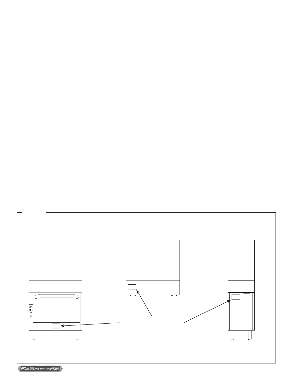
The location of the serial plate depends on the type of base (see Figure 1 below). On models with oven bases, the
serial plate is located on the backside of the kick-plate below the oven door (lift the kick-plate straight up and tilt the top
edge out and down.) On models with a cabinet base, the serial plate is located inside the left cabinet door. On modular
(countertop) models, the serial plate is located inside the front valve panel.
Read these instructions carefully before attempting installation. Installation and initial startup should be performed by
a qualied installer. Unless the installation instructions for this product are followed by a qualied service technician (a
person experienced in and knowledgeable with the installation of commercial gas and/or electric cooking equipment) then
the terms and conditions on the Manufacturer’s Limited Warranty will be rendered void and no warranty of any kind shall
apply.
In the event you have questions concerning the installation, use, care, or service of the product, contact:
Figure 1
Location of Serial Plate
Southbend Technical Service
1100 Old Honeycutt Road
Fuquay-Varina, North Carolina 27526 USA
www.southbendnc.com
Location of Serial Plate
OWNER’S MANUAL 1185836 REV 8 (9/14)
PAGE
3
OF 47
Page 3
PLATINUM SERIES RANGE
SPECIFICATIONS
SPECIFICATIONS
NOTICE
Local codes regarding installation vary greatly from one area to another. The National Fire Protection Association,
Inc., states in its NFPA 96 latest edition that local codes are the “authority having jurisdiction” when it comes to
installation requirements for equipment. Therefore, installations should comply with all local codes.
Southbend reserves the right to change specications and product design without notice. Such revisions do not entitle
the buyer to corresponding changes, additions, or replacements for previously purchased equipment.
Southbend appliances are intended for commercial use only, not for household use.
The installation must conform with local codes, or in the absence of local codes, with the National Fuel Gas Code,
ANSI Z223.1, Natural Gas Installation Code, CAN/CGA-B149.1, or the Propane Installation Code CAN/CGA-B149.2,
as applicable, including:
1. The appliance and its individual shutoff valve must be disconnected from the gas supply piping system during any
pressure testing of that system at test pressures in excess of 1/2 psi (3.45 kPa).
2. The appliance must be isolated from the gas supply piping system by closing its individual manual shutoff valve
during any pressure testing of the gas supply piping system at test pressures equal to or less than 1/2 psi (3.45 kPa).
CLEARANCES
WARNING
MINIMUM CLEARANCES FROM COMBUSTIBLE CONSTRUCTION
There must be adequate clearance between the cooking equipment and combustible construction. Clearance must
also be provided for servicing and for operation.
Plancha
Open-Top
Standard-Burner
Models
Sides 10” 13” 10” 10” 6”
Back 6” 6” 12” 12” 6”
Floor* 0” 0” 0” 0” 0”
Open-Top
PyroMax-Burener
Models
Griddle
Models
Uniform Hot-Top
Models
Graduated
Hot-Top
Models
Do NOT install sectional charbroilers or wood smokers next to combustible materials.
* Models with 6” legs or casters are suitable for installation on combustible oors.
Adequate clearance must be provided in the aisle in front of the unit to permit operation (including opening of doors
and/or removal of grease drawers, drippings trays, and/or oven racks), as well as for servicing. No additional clearance
is required for servicing as the sectional range is serviceable from the front.
Models with a convection-type oven require a minimum clearance of 2” between the motor on the back and
non-combustible construction. Care must be taken to provide adequate air circulation to prevent the motor from
overheating.
Minimum clearance from noncombustible construction is zero on the sides and back for all models (except for models
with a convection-type oven).
The high-temperature ue products ow out through the top of the ue riser of all models, and from the top of open-top
and charbroiler models. Installation under a vented hood is recommended.
Salamander broilers and cheese melters mounted on the ue riser of a sectional range may require additional
minimum clearances (see the documentation for those appliances).
PAGE
4
OF 47
OWNER’S MANUAL 1185836 REV 8 (9/14)
Page 4

PLATINUM SERIES RANGE
SPECIFICATIONS
VENTILATION
WARNING
Improper ventilation can result in personal injury or death. Ventilation which fails to properly remove ue products
can cause headaches, drowsiness, nausea, or could result in death.
All gas appliances must be installed in such a manner that the ow of combustion and ventilation air is not obstructed.
Provisions for adequate air supply must be provided. Do not obstruct the area under the control panel or below the
oven door (on the front), or the area below the ue riser (on the back) as combustion air enters through these areas.
NOTICE
Proper ventilation is the owner’s responsibility. Any problem due to improper ventilation will not be covered by the
warranty.
Be sure to inspect and clean the ventilation system according to the ventilation equipment manufacturer’s
instructions.
Air for combustion enters from the front below the valve panel, as well as from the rear into the burner box. Ranges
with solid tops (griddles, planchas and hot-tops) vent their ue products up the ue riser. On units with a base oven,
combustion air enters from the front below the oven door. Oven ue products are vented up the ue riser.
Lack of sufcient ventilation will cause poor burner and pilot operating characteristics, resulting in inefcient
performance. Such conditions also cause high ambient temperatures at the manifold area and create valve and
thermostat problems.
If a ventilation canopy is used, it is recommended that the canopy extend 6” past the sectional range and that the
bottom edge be located 6’6” from the oor. Filters should be installed at an angle of 45° or more from the horizontal.
This position prevents dripping grease, and facilitates collecting the run-off grease in a drip pan under the lter.
A strong exhaust fan tends to create a vacuum in the room and may interfere with burner performance or may
extinguish pilot ames. Fresh air openings approximately equal to the fan area will relieve such a vacuum. The
exhaust fan should be installed at least 2” above the top of the ue riser.
If the sectional range is connected directly to an outside ue, a CSA design certied down draft diverter must be
installed.
In case of unsatisfactory performance by any gas appliance, check the appliance with the exhaust fan turned OFF. Do
this only long enough to check whether doing so corrects any problems with equipment performance. Then turn the
exhaust fan back on and let it run to remove any exhaust that may have accumulated during the test.
GAS SUPPLY
The sectional range is design-certied for operation on natural or propane gases. The sectional range is shipped
congured and adjusted for the type of gas specied by the purchaser, which is indicated on the serial plate (see
Figure 1 on page 3). Connect the sectional range ONLY to the type of gas for which it is congured and adjusted.
Each section has a 1-1/4” front gas manifold that can be coupled to adjacent section(s). Sections can be ordered with
an optional 1” rear gas connection with a male NPT connector. Minimum supply pressure is 7” W.C. for natural gas,
11” W.C. for propane. An external pressure regulator and shut off valve must be provided. If using a exible-hose
gas connection, the I.D. of the hose must not be smaller than the connector on the unit and must comply with ANSI
Z21.69. Provide an adequate means of restraint to prevent undue strain on the gas connection.
If applicable, the vent line from the gas appliance pressure regulator shall be installed to the outdoors in accordance
with local codes, or in the absence of local codes, with the National Fuel Gas Code, ANSI Z223.1, Natural Gas
Installation Code, CAN/CGA-B149.1, or the Propane Installation Code CAN/CGA-B149.2, as applicable.
An adequate gas supply is imperative. Undersized or low pressure lines will restrict the volume of gas required for
satisfactory performance. Fluctuations of more than 25% on natural gas or 10% on propane gas will create problems
and affect burner operating characteristics. A 1/8” pressure tap is located on the manifold to measure the manifold
pressure. The supply line to the sectional range should be no smaller than the inside diameter of the pipe on the
sectional range to which it is connected.
OWNER’S MANUAL 1185836 REV 8 (9/14)
PAGE
5
OF 47
Page 5

PLATINUM SERIES RANGE
SPECIFICATIONS
ELECTRICITY SUPPLY
Units with convection-oven bases with optional electronic ignition require electric power (50Hz or 60Hz single-phase
AC). 120V models have a 7-foot (2134 mm) power cord with a grounded plug (1.0 amps for “D” Models and 4.8 amps
for “A” Models). The 208/240V models have a terminal block for connection to a single-phase 208/240V source (1.0
amps for “D” Models and 2.6 amps for the “A” Models).
The appliance, when installed, must be electrically grounded in accordance with local codes, or in the absence of local
codes, with the National Electrical Code, ANSI/NFPA 70, or the Canadian Electrical Code, CSA C22.2, as applicable.
An electrical diagram is located on the rear of the range, near the motor.
PAGE
6
OF 47
OWNER’S MANUAL 1185836 REV 8 (9/14)
Page 6

PLATINUM SERIES RANGE
OPERATION
OPERATION
DANGER
EXPLOSION HAZARD
In the event a gas odor is detected, shut down equipment at the main shut off valve. Immediately call the emergency
phone number of your gas supplier.
CAUTION
If a pilot ame pilot should go out, the ow of gas to the corresponding burner is NOT interrupted. Consequently, it
is the responsibility of the operator to check the ignition of each burner immediately EVERY TIME a burner is turned
on. Should ignition fail after 10 seconds, turn off the burner, wait 5 minutes, and then try again.
LIGHTING AFTER GAS HAS BEEN SHUT OFF
When turning on the main gas supply to a sectional range, do the following:
1. Make sure that all the control knobs and power switches of all the connected appliances are in the OFF position.
2. Turn on the gas-supply shut-off valve(s).
3. Light the standing pilots of each connected appliance.
4. Light the ovens of the sectional range rst, then wait six minutes before turning on the top sections.
This enables all air to be purged from the sectional-range gas piping.
SHUTDOWN OF ENTIRE RANGE
To place the range in a standby state (ready for use), Oven bases with the electronic ignition option, turn all burner
control knobs to OFF, set all thermostats to their lowest position, and switch all ovens OFF. The pilots will remain lit.
On the standing pilot units, same as above except turn thermostat knob to the “OFF” position. The pilots will remain lit.
To completely shut down the range for an extended period (or prior to disconnecting the gas supply), place the range
in a standby state (as described in the previous paragraph), then turn OFF the manual shut-off valves of all gas supply
connections. This will extinguish the pilots.
OWNER’S MANUAL 1185836 REV 8 (9/14)
PAGE
7
OF 47
Page 7

PLATINUM SERIES RANGE
Figure 8
Operation of Plancha Griddle Sections
OPERATION
Each control knob can be turned to OFF or to any position in
the range from low to high.
To start cooking, turn the control knob to HIGH. Check that the
burner ignites. The gas does NOT automatically shut off if
the burner does not ignite! If the burner does not ignite, check
and/or light the pilots (see procedure at right). When the burner
is hot, the burner ame should appear blue and steady (some
slight yellowing of the ame tips may occur when using propane
gas).
Always remember to heat the Plancha slowly because quick
heating may cause costly damage. Never place utensils on the
griddle.
Do not waste gas and abuse equipment by leaving the
Plancha on HIGH all the time. Damage to the Placha and
certain electronic components may occur, and MAY VOID
YOUR WARRANTY.
When necessary while cooking, pull out and empty the grease
drawer.
When done cooking, turn the appropriate control knob to OFF.
(The pilot should remain lit).
Each burner has a pilot that is lit using the spark igniter push
button, (if equipped) or a long match inserted thorough a hole
in the front valve panel. (A 32”-wide Plancha has three pilots.)
To light the pilot, do the following:
1. Check that all the control knobs are in the OFF position.
2. Turn on the gas supply to the sectional range (if not already
on).
3. Push spark ignition button for approximately 10 seconds.
4. Verify pilots are lit by looking through site holes in valve
panel. If spark ignition system is faulty, light pilots manually.
5. Pilots are lit manually by inserting a long match (at least 11”
long) or pilot-lighting device straight into the hole on the front
valve panel for each burner of the Plancha.
Burner Control Knob
(OFF, LOW-to-HIGH)
Pilot-Lighting
Opening
Push Button
Ignitor
Grease Drawer
(slides out for cleaning)
PAGE
14
OF 47
OWNER’S MANUAL 1185836 REV 8 (9/14)
 Loading...