

Page 1

southbend
A MIDDLEBY COMPANY
OWNER'S MANUAL
INSTALLATION
USER'S GUIDE
ELECTRIC TRI-LEG FULL JACKET KETTLE
KELS-20F, KELS-30F, KELS-40F MODELS:
KELS-60F, KELS-80, KELS-100
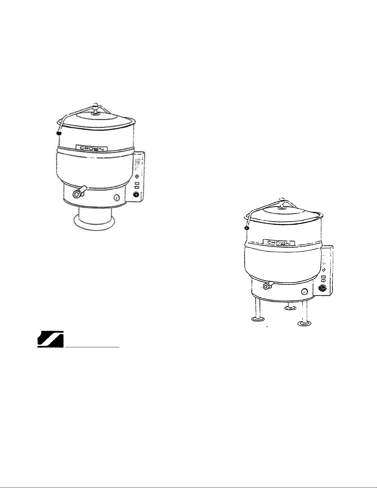
ELECTRIC PEDESTAL KETTLE
KEPS-20, KEPS-30, KEPS-40 MODELS:
KEPS-60, KEPS-80, KEPS-100
These instructions should be read thoroughly before attempting installation. Set up, installation and
Performance Check should be performed by a qualified service technician. The Manufacturer.
Southbend (1100 Old Honeycutt Rd., Fuquay-Varina, North Carolina 27526), informs you that
unless the installation instructions for the above described Southbend product are followed and
performed by a qualified service technician, (a person experienced in and knowledgeable
concerning the installation of commercial gas and/or electrical cooking equipment) then the terms
and conditions of the Manufacturer's Limited Warranty will be rendered void and no warranty of any
kind shall apply.
If the equipment has been changed, altered, modified or repaired by other than a qualified service
technician during or after the 12-month limited warranty period, then the manufacturer shall not be
liable for any incidental or consequential damages to any person or to any property which may result
from the use of the equipment thereafter. Some States do not allow the exclusion or limitation of
incidental or consequential damages, so the above limitation or exclusion thereto may not apply to
you.
In the event you have any question concerning the installation, use. care. or service of the product,
write Customer Service Department, Southbend Corporation. 1100 Old Honeycutt Rd., FuquayVarina. North Carolina 27526.
Page 2
INSTALLATION AND OPERATION
MODELS
EP-100
1100
Old Honeycutt Road
Fuquay
-
Varina, NC
27526
(
919) 552
-
9161 FAX (919) 552
-
9798 (800) 348
-
2558
MANUAL
SELF-GENERATING STEAM JACKETED KETTLES
MODELS
EL-20
EL-30
EL-40
EL-60
EL-80
EL-100
EP-20
EP-30
EP-40
EP-60
EP-80
southbend
A MIDDLEBY COMPANY
Page 3

INSTALLATION AND OPERATION
It is recommended that this manual be read thoroughly and that all instructions be followed carefully. This
manual should be retained for future reference.
DO NOT ATTEMPT TO OPERATE THIS UNIT IN THE EVENT OF A POWER FAILURE
ADEQUATE CLEARANCES MUST BE MAINTAINED FOR SAFE AND PROPER OPERATION
I N D E X
DESCRIPTION PAGE
INDEX 1
INSTALLATION AND SERVICE CONNECTIONS 2
INSTALLATION INSTRUCTIONS 4
INTRODUCTION 5
OPERATION INSTRUCTIONS 7
CLEANING INSTRUCTION 8
TROUBLESHOOTING 9
Page 4
INSTALLATION AND SERVICE CONNECTIONS
Model 208V 230V 240V 380V 415V 480V
KW AMP KW AMP KW AMP KW AMP KW AMP KW AMP
EL-20 12 33.4 12 30.1 12 28.9 12 18.3 12 16.7 12 14.5
EL-30 15 41.7 15 37.7 15 36.1 15 22.8 15 20.8 15 18
EL-40 18 50 18 45.2 18 43.4 18 27.4 18 25 18 21.7
EL-60 18 50 18 45.2 18 43.4 18 27.4 18 25 18 21.7
EL-80 18 50 18 45.2 18 43.4 18 27.4 18 25 18 21.7
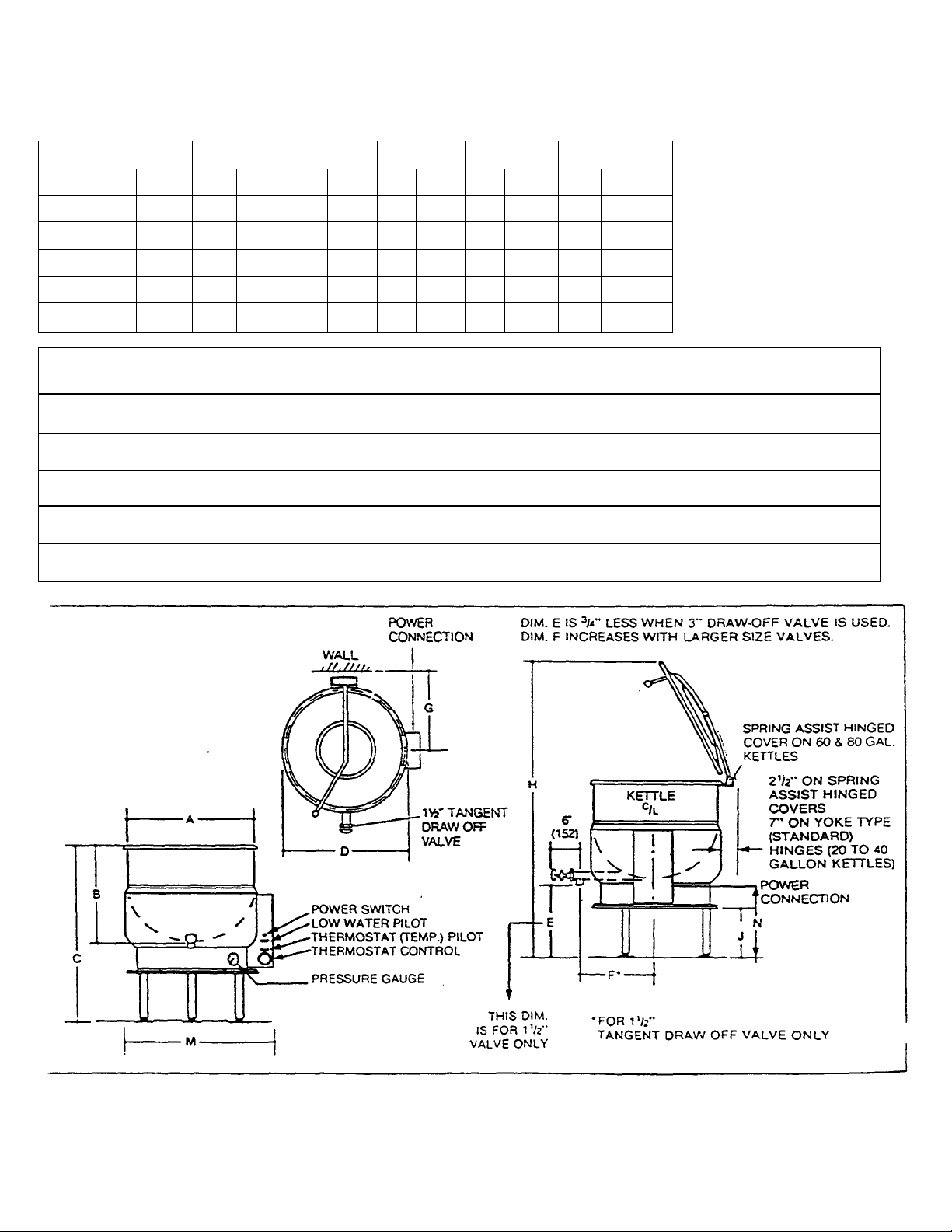
Model Capacity A B C D E F G H J M N
EL-20
EL-30
EL-40
EL-60
EL-80
20 U.S. gal.
76 liter
30 U.S. gal.
174 lifer
40 U.S. gal.
752 liter
60 U.S. gal.
227 liter
80 U.S. gal.
303 liter
inches
mm
inches
mm
inches
mm
inches
mm
inches
mm
21
533
24
670
26
660
29-1/2
749
33
838
18
457
20
508
22-1/2
572
26
660
28
777
38
965
38
965
38
965
42
1067
45
7743
22-3/4
578
25-3/4
654
27-3/4
705
31-1/4
1029
34-3/4
883
18
457
16
406
13-1/2
343
14
356
15
387
13-3/4
350
15
387
16
406
17
432
18-1/2
470
18-1/2
470
20
508
21
533
19
483
20-1/2
527
60-1/2
7537
63-1/2
7673
65
7657
75
7905
81
2058
14
356
12-1/2
378
9
229
11
250
123/4
324
24-3/4
629
27-3/4
705
29-3/4
756
33-3/4
857
36-3/4
933
21
533
19
483
17
432
171/4
438
18
458
As continued product improvement is a policy of Crown. specifications are subject to change without notice
Page 5

INSTALLATION AND SERVICE CONNECTIONS
227
liter
mm
660
7067
356
349
483
280
303 liter
mm
838
711
7743
387
363
Model 208V 230V 240V 380V 415V 480V
KW AMP KW AMP KW AMP KW AMP KW AMP KW AMP
EP20 12 33.4 12 30.1 12 28.9 12 18.3 12 16.7 12 14.5
EP30 15 41.7 15 37.7 15 36.1 15 22.8 15 20.8 15 18
EP40
EP60 18 50 18 45.2 18 43.4 18 27.4 18 25 18 21.7
EP80 18 50 18 45.2 18 43.4 18 27.4 18 25 18 21.7
Model Capacity
EP-20
EP-30
EP-40
EP-60
EP-80
18 50 18 45.2 18 43.4 18 27.4 18 25 18 21.7
20 U.S. gal.
76 liter
30 U.S. gal.
114 liter
40 U.S. gal.
752 liter
60 U.S. gal.
80 U.S. gal.
inches
mm
inches
mm
inches
mm
inches
inches
A B C D E F G H J M
21
533
24
670
26
660
29-1/2
749
33
18
457
20
508
22-1/2
572
26
28
38
965
38
965
38
965
42
45
22-3/4
578
25-3/4
654
27-3/4
705
31-1/4
7029
42-1/2
7080
18
457
16
406
13-1/2
343
14
15
12
305
12-3/4
324
13-1/4
337
13-3/4
14-1/2
16-1/2
479
16-1/2
479
17
432
19
20-1/2
527
60-1/2
7537
63-1/2
7673
64-1/2
7638
72-1/2
7842
79-1/2
2020
14
356
12-3/8
374
10
254
11
12-5/8
327
17-1/4
438
17-1/4
438
17-1/4
438
17-1/4
438
19-1/4
489
As continued product improvement is a policy of Crown, specifications are subject to change without notice
Page 6

INSTALLATION INSTRUCTIONS
SELF-GENERATING STEAM JACKETED TILTING FLOOR
MOUNTED KETTLES
a) Select a location to provide drainage directly below the tangent Draw-Off. Allow sufficient rear clearance from wall
for kettle cover to lift upright freely and completely without obstructions.
b) Mark hole locations through flanged adjustable feet on ELT models. Remove kettle.
c) On hole locations marked, drill holes and insert expansion shields to accommodate 5/16" size lag bolts.
d) Reposition kettle. On EL models level by making necessary adjustments on flanged feet.
e) Bolt down kettle and seal with Silastic or other equivalent sealing compound. Sealant must be applied not only to
bolt heads but also around flanges or pedestal base making contact with floor surface to fulfill NSF requirements.
Wipe off excess sealant immediately.
g) A Control Box with power supply equivalent to Electrical Rating of kettle should be located conveniently nearby.
h) A water proof electrical connection for power supply to rear of control housing must be provided.
i) Ground kettle to terminal provided inside control housing.
j) Turn power ON and check for proper operation.
Page 7

INTRODUCTION
SELF-GENERATING STEAM JACKETED TILTING FLOOR
MOUNTED KETTLES
DESCRIPTION
All electrically power kettles described and referred to in this Manual are pressure vessels of a double-wall stainless steel
construction forming a sealed jacket (chamber) enveloping the lower two thirds of the kettle bowl surface.
The kettle bowl is the container for the food product which ideally should be a liquid or semi-liquid consistency to achieve
complete contact with the bowl surface and thus fully absorb the heat transmitted through that surface from the
pressurized steam generated in the kettle jacket.
The jacket is intended to function as a self contained sealed chamber with a permanent solution of water and anti-freeze
sufficient not only to immerse and thereby protect replaceable electric heating elements but also provide the steam source
during the steam generating process.
The heating elements are thermostatically dial controlled to provide precise temperatures throughout the range from slow
simmer to rolling boil.
All stationary kettles are intended to be permanently floor mounted on legs with adjustable flanged feet (EL models) or
pedestals (EP Models).
All kettles are equipped with a hinged counterbalanced stainless steel lid covering the kettle bowl opening, a sanitary
stainless steel tangent draw-off valve for the removal of the food product from the kettle bowl, and a safety relief valve
plumbed to the kettle jacket.
CAPACITIES
All models are suffixed with either -20, -30, -40, -60, -80 or 100 to indicate the capacity of that kettle in US gallons. Thus
an EL-40 indicates a two thirds jacketed electrically powered steam kettle mounted on legs with a capacity of 40 gallons
(US). If the letter F is added to the suffix, this then indicates that the kettle is full jacketed as averse to two thirds jacketed.
Thus an EP-30F indicates a full jacketed electrically powered steam kettle mounted on a pedestal with a capacity of 30
gallons.
FUNCTIONING MODE
All electrically powered self steam generating kettles consist of a jacket containing a permanent solution of water and antifreeze sufficient to completely immerse and protect replaceable electric heating elements.
Page 8

To minimize tampering, the Safety Valve is plumbed towards the rear the kettle jacket. Should any component
malfunction and cause the pressure in the jacket to reach the rated pressure of the kettle this protective device will open
automatically and release excessive pressurized steam.
When the Power Switch is turned ON and the Temperature Control (Thermostat) Knob dialed, simultaneously
TEMPERATURE pilot light will glow and contactors will close to allow power to elements and steam generation will
commence and continue until the water contained in the jacket reaches the thermostatic temperature manually preselected, at which point the Temperature (thermostat) Control will de-energize and open the contactors cutting of power
to heating elements and TEMPERATURE pilot light will go off. When the temperature of the water in the jacket drops
slightly, the cycle will repeat itself thus making it possible to maintain any selected precise cooking mode temperature.
The temperature required for the cooking process to function adequately must be greater than the boiling point of the
liquid food product, viz. water. Further, the higher the temperature, the greater the steam pressure attained in the jacket
and consequently the quicker the cooking process. For example, steam pressurized at 30 p.s.i. attains a temperature of
274 degrees fahrenheit.
Since air is an unsuitable media through which heat may be transferred, it has been removed from the kettle jacket during
testing at Crown. The Pressure Gauge should indicate vacuum in the jacket of approximately 20-25 inches HG when the
kettle is cold or has been inoperative for sometime. The kettle jacket is intended to function at all times as a completely
sealed self contained chamber and it is especially advisable not to trip the safety relief valve during inoperative periods
since this will break the vacuum seal and allow air to enter the kettle jacket.
It should be noted that Temperature Controls (thermostats) used on these particular kettles have an ultimate high limit
temperature and this setting will prevent the heating elements from ever generating steam pressure to reach or exceed
the rated working pressure of these kettles. Further should the Temperature Control fail, an unlikely condition, and
consequently the circuit to the heating elements remain energized, the Safety Valve will blow and release steam (i.e.
water) from the self contained sealed kettle jacket and consequently lower the water level in the jacket (but still maintain
elements in an immersed condition), whence the Safety Probe sensing depletion of the water level in the kettle jacket will
not only activate the LOW WATER level indicator pilot light but also signal the Liquid Level Control to switch off power
and de-energize the circuit to the heating elements (preventing element burn outs) until the water level is adequately
replenished.
Page 9

OPERATING INSTRUCTIONS
SELF-GENERATING STEAM JACKETED
TILTING FLOOR MOUNTED KETTLES
OPERATING INSTRUCTIONS
a) Check kettle Pressure Gauge that reading indicates 20-25 vacuum for a cold kettle. If vacuum is insufficient, Air
Venting Instructions must be followed. If equipped with Draw Off Valve ensure Valve is closed.
b) Place Kettle Power Switch in ON position.
Preheat kettle by turning Thermostat Knob to '8' and wait until Temperature pilot light goes off. c)
NOTE: Food products with milk or egg base should be placed into cold kettle and then the cooking
operation begun. Avoid sudden contact of these food products to hot kettle bowl surface
since caking/adhering will occur.
d) Place food product into kettle bowl. Close kettle cover.
e) Adjust Thermostat Knob to temperature cooking mode. Setting of 6-7 will provide simmer and 8-10 low to rolling
boil.
f) Turn both kettle Power Switch and Thermostat Knob OFF when cooking has been completed.
g) Remove food product by ladling out of kettle bowl or by opening Draw-Off Valve and pouring into a suitable
container,
Page 10

CLEANING INSTRUCTIONS
CLEANING PROCEDURE
Your kettle should be cleaned immediately after each use to prevent- food residue from drying and adhering to kettle bowl
and valve surfaces.
a) Turn power supply OFF to kettle.
b) Rinse inside of Kettle thoroughly. Drain kettle by tilting or if equipped with drain valve, open valve and remove all
food particles. Close drain valve.
c) Using nylon brush, clean kettle with a mild detergent and warm water rinse. Never use steel wool or scouring
powder as they will scratch stainless steel. Food adhering excessively to bowl surface may be loosened by
allowing water to soak in a bowl at a low temperature setting.
d) Open the Draw-Off to allow soap and water solution to drain.
e) By hand, turn large hex nut oh Draw-Off Valve counter clockwise until completely disengaged from thread. Grasp
Valve knob and pull out valve steam and disc slowly. Avoid contact of Valve disc with hard surfaces since
damage to disc may occur and result in valve leakage. Wash the valve stem. disc and handles. Insert nylon
brush with detergent into interior of valve body and tangent draw-off tube and brush vigorously.
f) Replace valve stem assembly and engage hex nut fully by hand. Flush kettle with clean warm water and leave
Valve open when kettle is not in use.
g) Wipe down exterior of kettle with clean damp cloth.
WARNING
It is NOT RECOMMENDED to use cleaning agents that are corrosive.
Use of cleaning agents that contain chloride, acids or salts are corrosive and may cause pitting and corrosion when used
over a period of time; this will reduce the life of the appliance.
Should pitting or corrosion occur this is not covered by warranty.
Follow the recommended cleaning instructions. Use a mild detergent, warm water and rinse thoroughly.
NEVER SPRAY WATER INTO ELECTRIC CONTROLS
Page 11

TROUBLESHOOTING
EL-60 and EP
-
60 Models add
250
ozs.
SELF-GENERATING STEAM JACKETED TILTING
FLOOR MOUNTED KETTLE
GENERAL MAINTENANCE
No general maintenance is required other than adhering to the Cleaning Procedure instructions.
LOW WATER LEVEL
Proper water level must be maintained within the jacket for the kettle to operate. Depletion of water may occur from
excessive opening of, or leakage through the safety relief valve.
If water is below required operating level, either initially at start-up or during use, the kettle will automatically shut off,
refuse to operate and the LOW WATER signal light will come on.
In order for the kettle to operate, the following procedure must be followed:
a) Trip the safety relief valve lever to relieve all pressure from the kettle jacket.
b) At exterior rear of kettle jacket remove nut from Air Vent.
c) Insert funnel into Air Vent opening and slowly add the indicated amount of clean water for:
EL-20 and EP-20 Models add 140 ozs.
EL-30 and EP-30 Models add 150 ozs.
EL-40 and EP-40 Models add 220 ozs.
EL-80 and EP-80 Models add 330 ozs.
EL-100 and EP-100 Models add 420 ozs.
d) Replace Air Vent nut.
e) Follow Air Venting Instructions below.
f) Continue normal Operating Procedure of kettle.
Page 12

AIR VENTING INSTRUCTIONS
Periodically check Pressure Gauge when the kettle is cold. Reading should be in (green) VACUUM zone between 20 to
25, otherwise air is present and efficient heating will not occur.
To remove air, set Thermostat Knob at 8 and heat empty kettle until TEMPERATURE pilot light goes off.
Open Air Vent nut one full turn for 10 seconds to exhaust air from kettle jacket. Close Air Vent nut.
 Loading...