

Page 1
IMPORTANT FOR FUTURE REFERENCE
Please complete this information and retain this
manual for the life of the equipment:
Model #: ___________________________
Serial #: ___________________________
Date Purchased: ____________________
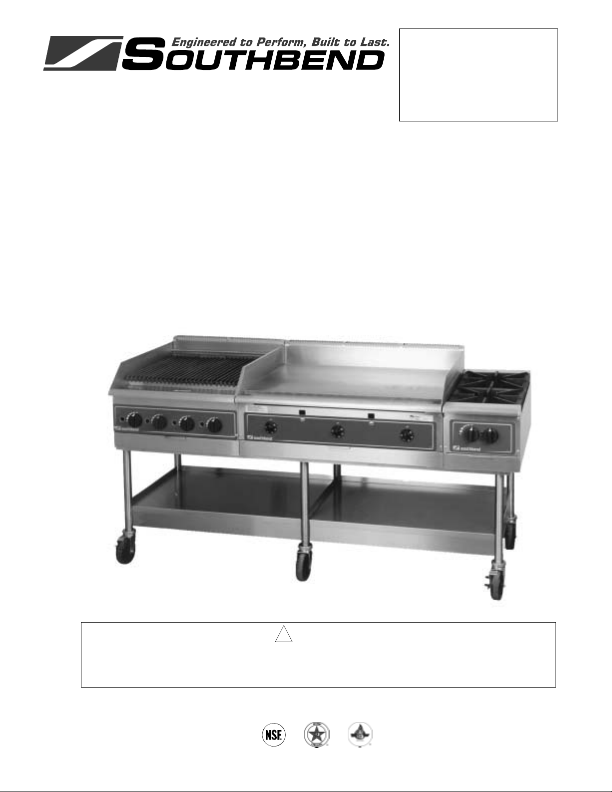
OWNER’S MANUAL
Heavy Duty Counterline
Griddle Models Charbroiler Models Open Top Models
HDG-24
HDG-36
HDG-48
HDG-60
HDG-72
HDG-36-RE
HDG-48-RE
HDG-60-RE
HDG-72-RE
HDG-24-M
HDG-36-M
HDG-48-M
HDG-60-M
HDG-72-M
HDC-24
HDC-36
HDC-48
HDCL-24
HDCL-36
HDCL-48
HDO-12
HDO-24
HDO-36
HDO-24SU
HDO-36SU
! WARNING
Improper installation, adjustment, alteration, service or maintenance can cause property damage,
injury or death. Read the installation, operating and maintenance instructions thoroughly before
installing or servicing this equipment.
1100 Old Honeycutt Road, Fuquay-Varina, NC 27526
www.southbendnc.com
MANUAL 1182845 REV 8
$21.00
HEAVY DUTY COUNTERLINE
MANUAL SECTION HD
Page 2
HEAVY DUTY COUNTERLINE
SAFETY PRECAUTIONS
Before installing and operating this equipment, be sure everyone involved in its operation is fully trained
and aware of precautions. Accidents and problems can be caused by failure to follow fundamental rules
and precautions.
The following symbols, found throughout this manual, alert you to potentially dangerous conditions to the
operator, service personnel, or to the equipment.
! DANGER
! WARNING
! CAUTION
NOTICE
This symbol warns of immediate hazards that will result in severe injury or
death.
This symbol refers to a potential hazard or unsafe practice that could result in
injury or death.
This symbol refers to a potential hazard or unsafe practice that could result in
injury, product damage, or property damage.
This symbol refers to information that needs special attention or must be fully
understood, even though not dangerous.
! WARNING
FIRE HAZARD
FOR YOUR SAFETY
Do not store or use gasoline or other flammable vapors and liquids in the vicinity of this or any other
appliance.
Keep area around appliances free and clear of combustibles.
Purchaser of equipment must post in a prominent location, detailed instructions to be followed in the
event the operator smells gas. Obtain the instructions from the local gas supplier.
! WARNING
Asphyxiation can result from improper ventilation. Do not obstruct the flow of combustion and
ventilation air to and from your cooking equipment.
NOTICE
Be sure this Operator’s Manual and important papers are given to the proper authority to retain for
future reference.
NOTICE
This product is intended for commercial use only. NOT FOR HOUSEHOLD USE.
PAGE 2OWNER’S MANUAL 1182845 REV 8
Page 3
HEAVY DUTY COUNTERLINE TABLE OF CONTENTS
Congratulations! You have purchased one of the finest pieces of commercial cooking equipment on the
market.
You will find that your new equipment, like all Southbend equipment, has been designed and manufactured
to meet the toughest standards in the industry. Each piece of Southbend equipment is carefully engineered
and designs are verified through laboratory tests and field installations. With proper care and field
maintenance, you will experience years of reliable, trouble-free operation. For best results, read this
manual carefully.
RETAIN THIS MANUAL FOR FUTURE REFERENCE.
Table of Contents
Specifications .........................................................................................................................4
Installation ..............................................................................................................................9
Operation..............................................................................................................................21
Cleaning ...............................................................................................................................26
Adjustments..........................................................................................................................28
Troubleshooting....................................................................................................................32
Parts .....................................................................................................................................33
Read these instructions carefully before attempting installation. Installation and initial startup should be
performed by a qualified installer. Unless the installation instructions for this product are followed by a
qualified service technician (a person experienced in and knowledgeable with the installation of commercial
gas an/or electric cooking equipment) then the terms and conditions on the Manufacturer’s Limited
Warranty will be rendered void and no warranty of any kind shall apply.
In the event you have questions concerning the installation, use, care, or service of the product, write to:
Southbend
1100 Old Honeycutt Road
Fuquay-Varina, North Carolina 27526 USA
www.southbendnc.com
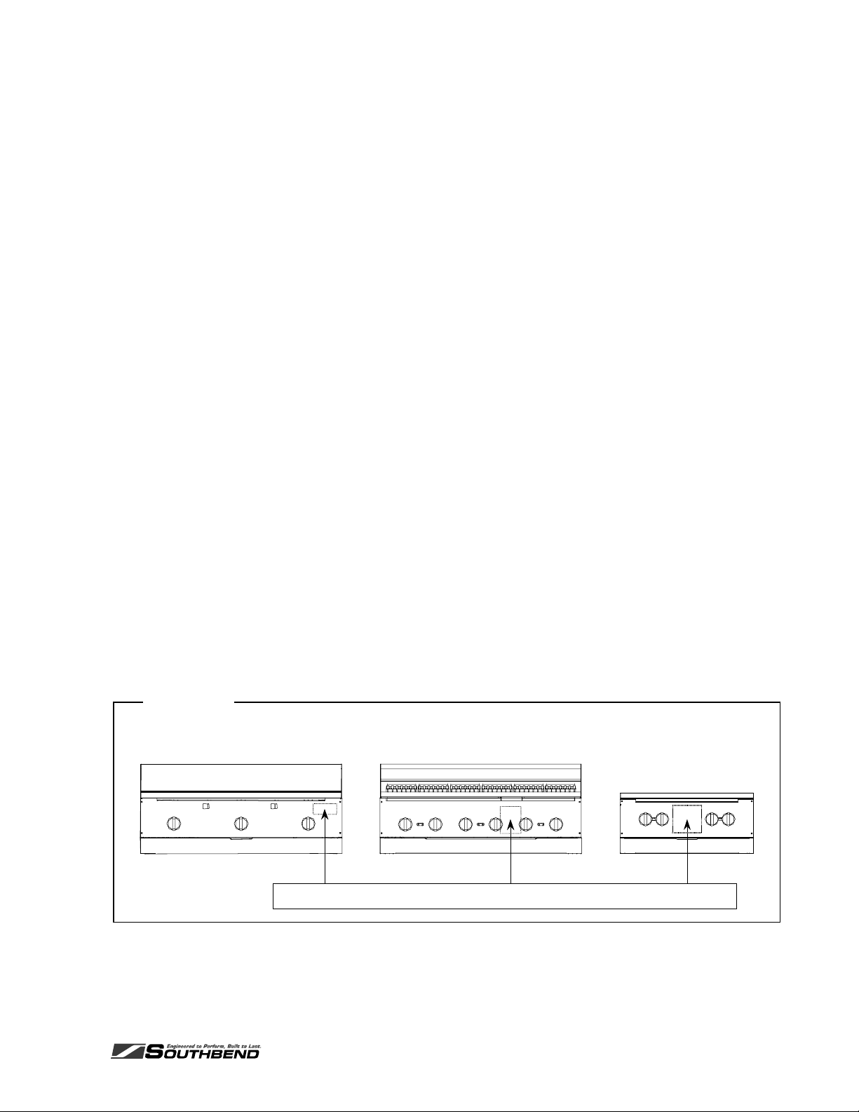
The serial plate is located on the interior side of the valve panel, as shown below:
Figure 1
Griddle Models
Serial plate of each model is located on the interior side the valve panel.
Charbroiler Models
Open TopModels
OWNER’S MANUAL 1182845 REV 8PAGE 3
Page 4
SPECIFICATIONS HEAVY DUTY COUNTERLINE
SPECIFICATIONS
SPECIFICATIONS
GAS SUPPLY
The serial plate is located on the interior side of the valve panel (see Figure 1 on page 3). It indicates the
type of gas the unit is equipped to burn. All Southbend equipment is adjusted at the factory. Check type of
gas on serial plate.
These models are design-certified for operation on natural or propane gases. The unit is shipped
configured for the type of gas specified by the purchaser. A kit for conversion to a different type of gas may
be purchased from Southbend (see page 30 for conversion instructions).
NOTICE
Installation must comply with National Fuel Gas Code, ANSI Z223.1, Natural Gas Installation Code,
CAN/CGA-B149.1, or the Propane Installation Code, CAN/CGA-B149.2, as applicable.
Local codes regarding installation vary greatly from one area to another. The National Fire Protection
Association, Inc. states in its NFPA 96 latest edition that local codes are the “authority having
jurisdiction” when it comes to installation requirements for equipment. Therefore, installations should
comply with all local codes.
Southbend reserves the right to change specifications and product design without notice. Such
revisions do not entitle the buyer to corresponding changes, additions, or replacements for previously
purchased equipment.
This product is intended for commercial use only, not for household use.
This appliance should be connected ONLY to the type of gas for which it is configured.
An adequate gas supply is imperative. Undersized or low pressure lines will restrict the volume of gas
required for satisfactory performance. Fluctuations of more than 25% on natural gas or 10% on propane
gas will create problems and affect burner operating characteristics. A 1/8" pressure tap is located on the
manifold to measure the manifold pressure.
An adequate gas supply line to the unit should be no smaller than the inside diameter of the pipe from the
unit to which it is connected.
Purge the supply line to clean out dust, dirt, or other foreign matter before connecting the line to the unit.
All pipe joints and connections must be tested thoroughly for gas leaks. Use only soapy water for testing on
all gases. NEVER use an open flame to check for gas leaks. All connections must be checked for leaks
after the unit has been put into operation. Test pressure should not exceed 14" W.C.
! CAUTION
THIS APPLIANCE AND ITS INDIVIDUAL SHUTOFF VALVE MUST BE DISCONNECTED FROM
THE GAS SUPPLY PIPING SYSTEM DURING ANY PRESSURE TESTING OF THAT SYSTEM AT
TEST PRESSURES IN EXCESS OF 1/2 PSIG (3.45 kPa).
THIS APPLIANCE MUST BE ISOLATED FROM THE GAS SUPPLY PIPING SYSTEM BY CLOSING
ITS INDIVIDUAL MANUAL SHUTOFF VALVE DURING ANY PRESSURE TESTING OF THE GAS
SUPPLY PIPING SYSTEM AT TEST PRESSURES EQUAL TO OR LESS THAN 1/2 PSIG (3.45
kPa).
PAGE 4OWNER’S MANUAL 1182845 REV 8
Page 5
HEAVY DUTY COUNTERLINE SPECIFICATIONS
CLEARANCES
! WARNING
There must be adequate clearance between units and adjacent construction. Clearance must also be
provided for servicing and for operation. Measure back clearance from rear of 2" stand-off bracket s.
Minimum Clearances from COMBUSTABLE construction:
Griddle Models Open Top Models
Sides 12" 10"
Back 8" 7"
Minimum Clearances from NON-COMBUSTABLE construction:
Griddle Models Charbroiler Models Open Top Models
Sides 0" 0" 0"
Back 0" 0" 0"
VENTILATION
! WARNING
SPECIFICATIONS
Improper ventilation can result in personal injury or death. Ventilation which fails to properly remove
flue products can cause headaches, drowsiness, nausea, or could result in death.
All units must be installed in such a manner that the flow of combustion and ventilation air are not
obstructed. Provisions for adequate air supply must be provided. Do not obstruct the front of the unit
at the top by the control panel as combustion air enters through these areas.
NOTICE
Proper ventilation is the owner’s responsibility. Any problem due to improper ventilation will not be
covered by the warranty.
Air for combustion enters the rear of the appliance. An exhaust flue runs along the top rear edge of griddle
and charbroiler models.
Southbend recommends that a ventilation canopy extend 6" past the edges of the appliance and be located
6'6" above the floor.
If a wall exhaust fan is installed in the wall behind the appliance, it should be at least two feet above the top
of the appliance.
To avoid a negative pressure condition, return air must be brought into the room to replenish the air being
removed by the ventilation exhaust fan. RETURN-AIR FANS MUST NOT BLOW DOWN ONTO THE
APPLIANCE.
Ventilation filters should be installed at an angle of 45° or more from the horizontal. This prevents dripping
grease and facilitates collecting the run-off grease in a drip pan, usually installed with a filter.
Be sure to inspect and clean the ventilation system according to the ventilation equipment manufacturer’s
instructions.
In case of unsatisfactory performance on any appliance, check the appliance with the ventilation exhaust
fan in the “OFF” position. Do this only long enough to check equipment performance. Then turn the fan
back on and let it run to remove any exhaust that may have accumulated during the test.
OWNER’S MANUAL 1182845 REV 8PAGE 5
Page 6
SPECIFICATIONS HEAVY DUTY COUNTERLINE
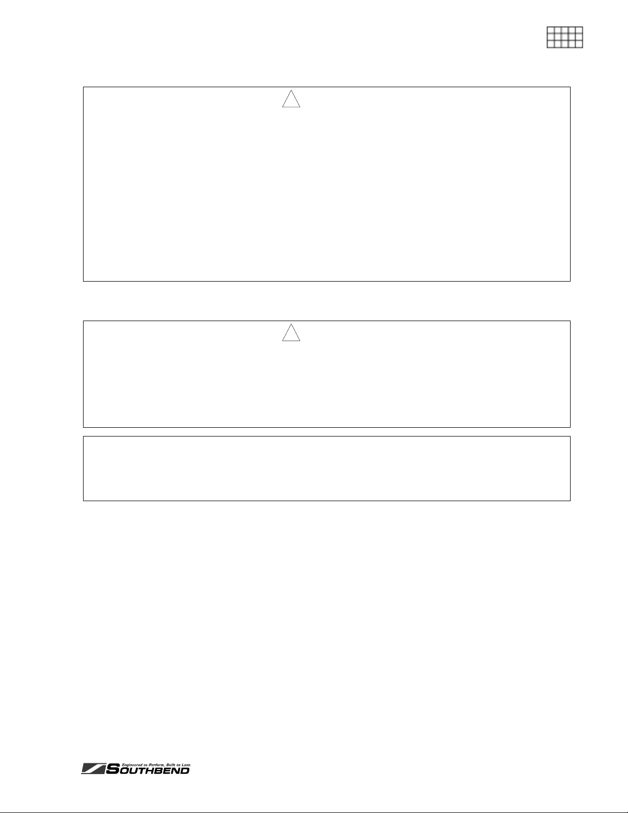
Figure 2
DIMENSIONS OF GRIDDLE MODELS
SPECIFICATIONS
16.0"
15.1"
10.0"
31.5"
2.0"
29.4"
Side View of Front-Trough Models
5.4"
Width ( see tablebelow)
Front View
1.5"
24.0"
Top View of Front-Trough Models
3"
11.0"
2.8"
30.0"
16.0"
24.0"
29.4"
Side View of Rear-Trough Models
2.625"
Top View of Rear-Trough Models
Model Width Number and Size of Burners Total BTU
HDG-24 & HDG-24-M 24" 2 @ 30,000 60,000
HDG-36, HDG-36-RE, & HDG-36-M 36" 3 @ 30,000 90,000
HDG-48, HDG-48-RE, & HDG-48-M 48" 4 @ 30,000 120,000
HDG-60, HDG-60-RE, & HDG-60-M 60" 5 @ 30,000 150,000
HDG-72, HDG-72-RE, & HDG-72-M 72" 6 @ 30,000 180,000
PAGE 6OWNER’S MANUAL 1182845 REV 8
Page 7
HEAVY DUTY COUNTERLINE SPECIFICATIONS
CONSTRUCTION OF GRIDDLE MODELS
The front, sides, and 5" riser are all stainless steel. The rear and bottom panels are aluminized steel. The
reinforced double-wall sides are fully insulated.
The griddle surface is high-carbon, 1" thick, polished steel plated with trivalent chromium. The chrome plate
has an emissivity rating of approximately 0.08.
Each foot of griddle plate is heated by a U-shaped burner controlled by a thermostatic gas valve for
independent temperature control. Each pilot is equipped with a flame failure safety device.
The base of 60" and 72" griddles consist of two burner compartments spanned by one griddle surface with
one grease duct and one grease drawer.
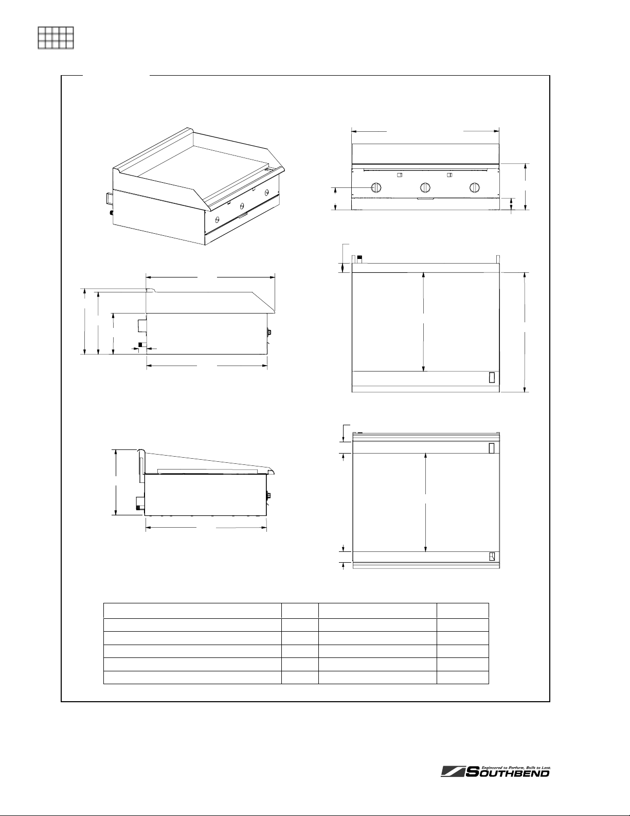
Figure 3
DIMENSIONS OF CHARBROILER MODELS
1.5"
SPECIFICATIONS
30.0"
5.3"
21.5"
Top View
Width(see tablebelow)
11.0"
2.8"
Front View Side View
31.5"
29.4"
16.0"
15.1"
10.0"
2.0"
Model Width Number and Size of Burners Total BTU
HDC-24 & HDCL-24 24" 4 @ 20,000 80,000
HDC-36 & HDCL-36 36" 6 @ 20,000 120,000
HDC-48 & HDCL-48 48" 8 @ 20,000 160,000
OWNER’S MANUAL 1182845 REV 8PAGE 7
Page 8
CONSTRUCTION OF CHARBROILER MODELS
The front, top-rail sides, and 5" riser are all stainless steel. The rear and bottom panels are aluminized
steel. The reinforced double-wall sides are fully insulated.
Each 6" section has a gas valve for independent control of flame. Each burner is covered by a stainless
SPECIFICATIONS
steel radiant or by a layer of ceramic briquettes.
The heavy cast iron grids have wide-branding (1/4") on one side and narrow branding (1/8" with grease
channel) on the other side. The tilt of each grid can be adjusted. Chrome-plated grids can be ordered for
cooking fish.
SPECIFICATIONS HEAVY DUTY COUNTERLINE
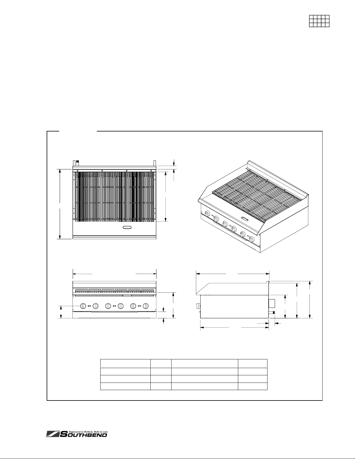
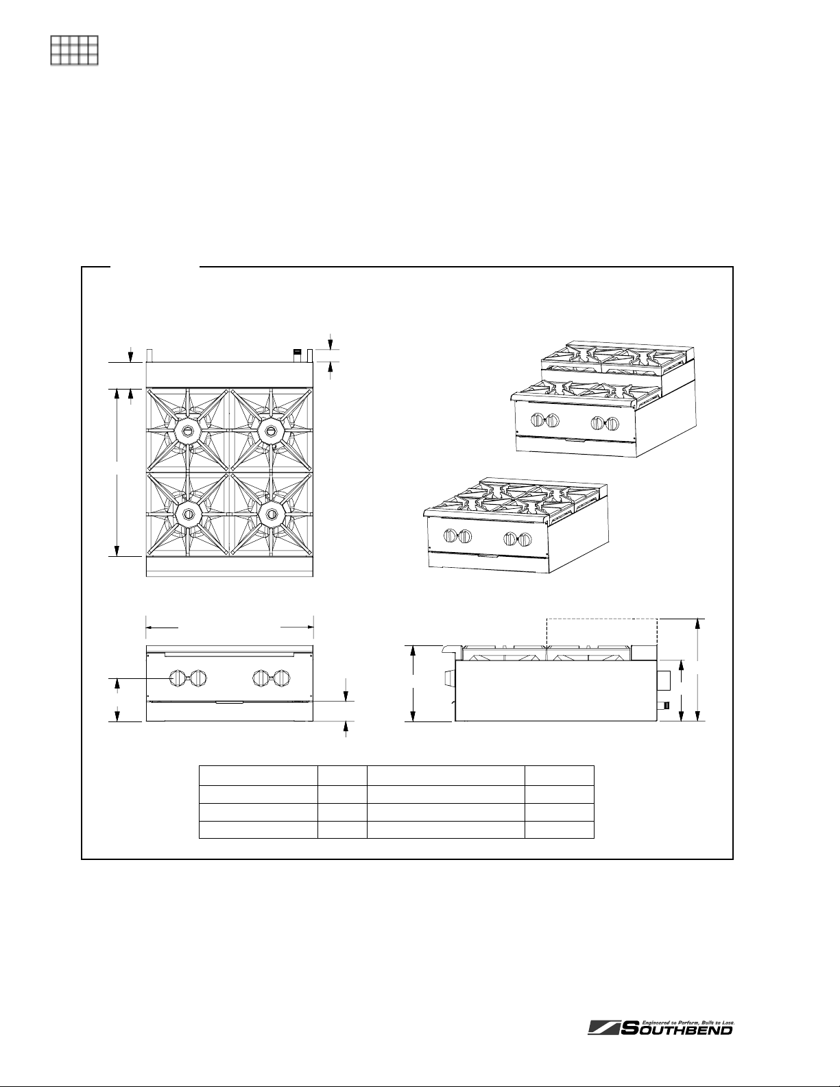
Figure 4
DIMENSIONS OF OPEN TOP MODELS
3.9"
2.0"
24.4"
6.3"
TopView
Width(seetablebelow)
2.8"
Front View
Model Width Number and Size of Burners Total BTU
HDO-12 12.25" 2 @ 26,000 52,000
HDO-24 & HDO-24SU 24.5" 4 @ 26,000 104,000
HDO-36 & HDO-36SU 36.625" 6 @ 26,000 156,000
11.0"
15.3"
9.0"
SideV iew
CONSTRUCTION OF OPEN TOP MODELS
The front, top-rail sides, and 5" riser are all stainless steel. The rear and bottom panels are aluminized
steel. The reinforced double-wall sides are fully insulated.
Each burner has its own gas valve, and is covered by a heavy cast iron grate.
Step-up models have elevated rear burners.
PAGE 8OWNER’S MANUAL 1182845 REV 8
Page 9
HEAVY DUTY COUNTERLINE INSTALLATION
INSTALLATION
NOTICE
Installation must comply with National Fuel Gas Code, ANSI Z223.1, Natural Gas Installation Code,
CAN/CGA-B149.1, or the Propane Installation Code, CAN/CGA-B149.2, as applicable.
These installation procedures must be followed by qualified personnel or warranty will be void.
Local codes regarding installation vary greatly from one area to another. The National Fire Protection
Association, Inc. states in its NFPA 96 latest edition that local codes are the “authority having
jurisdiction” when it comes to installation requirements for equipment. Therefore, installations should
comply with all local codes.
Step 1: Unpack
IMMEDIATELY INSPECT FOR SHIPPING DAMAGE
INSTALLATION
All containers should be examined for damage before and during unloading. The freight carrier has
assumed responsibility for its safe transit and delivery. If damaged equipment is received, either
apparent or concealed, a claim must be made with the delivering carrier.
Apparent damage or loss must be noted on the freight bill at the time of delivery. The freight bill must
then be signed by the carrier representative (Driver). If the bill is not signed, the carrier may refuse
the claim. The carrier can supply the necessary forms.
A request for inspection must be made to the carrier within 15 days if there is concealed damage or
loss that is not apparent until after the equipment is uncrated. The carrier should arrange an
inspection. Be certain to hold all contents plus all packing material.
1. Uncrate carefully. Report any hidden damage to the freight carrier IMMEDIATELY.
2. Do not remove any tags or labels until unit is installed and working properly.
Step 2: Attach Countertop Legs, Mount on Counter, or Mount on Stand
The appliance can be mounted in several ways:
To mount it on short, countertop legs, go to Step 2a on page 10.
To mount it directly on a countertop, go to Step 2b on page 11.
To mount it on an insulated base on a countertop, go to Step 2c on page 12.
To mount it on a stand that rests on the floor, go either to Step 2d on page 13 (for 24", 36", and 48"
models) or to Step 2e on page 15 (for 60" and 72" griddle models).
OWNER’S MANUAL 1182845 REV 8PAGE 9
Page 10
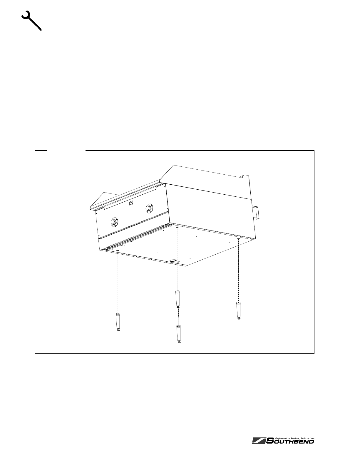
Step 2a: Installation on Countertop Legs
To install the appliance using countertop legs, do the following:
1. Locate the box of four legs shipped with the appliance (if countertop legs were ordered).
2. Raise the appliance about 6" so that the legs can be screwed into the bottom near the corners. Lift the
appliance only from the ends, never from the middle! Support the lifted appliance so that it will not fall
while you are attaching the legs.
3. Screw the four legs into the threaded holes located on the bottom of the appliance near each corner
(as shown in Figure 5 below).
4. Gently lower the appliance onto the counter. Level the appliance surface by screwing one or more of
the legs in or out.
INSTALLATION
5. Go on to Step 4 on page 18.
INSTALLATION HEAVY DUTY COUNTERLINE
Figure 5
PAGE 10 OWNER’S MANUAL 1182845 REV 8
Page 11
HEAVY DUTY COUNTERLINE INSTALLATION
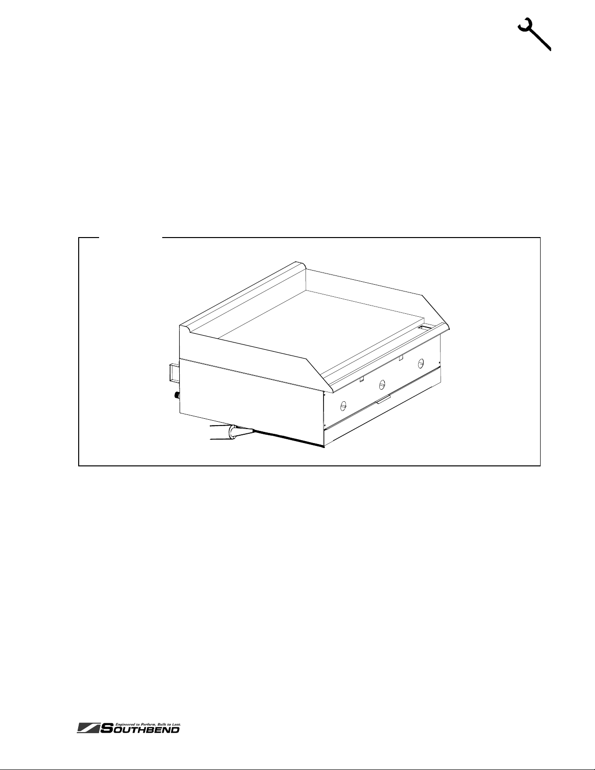
Step 2b: Installation Directly on a Non-Combustible Countertop Surface
The appliance may be installed directly onto a flat NON-COMBUSTIBLE surface, as follows:
1. Place the appliance in the position that it will be used. Lift the appliance only from the ends, never from
the middle!
2. Connect the gas supply (see Step 4 on page 18), then return to this procedure.
3. Check that the appliance is in the position you want it to be in.
4. Seal the appliance to the countertop using G.E. or Dow Corning RTV, or the equivalent (as shown in
Figure 6 below). Consult local codes for exact requirements. A small bead of RTV around all four
bottom edges should be adequate. Open the front door to seal along the front edge of the frame.
5. Go on to Step 5 on page 19.
Figure 6
INSTALLATION
OWNER’S MANUAL 1182845 REV 8PAGE 11
Page 12
INSTALLATION HEAVY DUTY COUNTERLINE
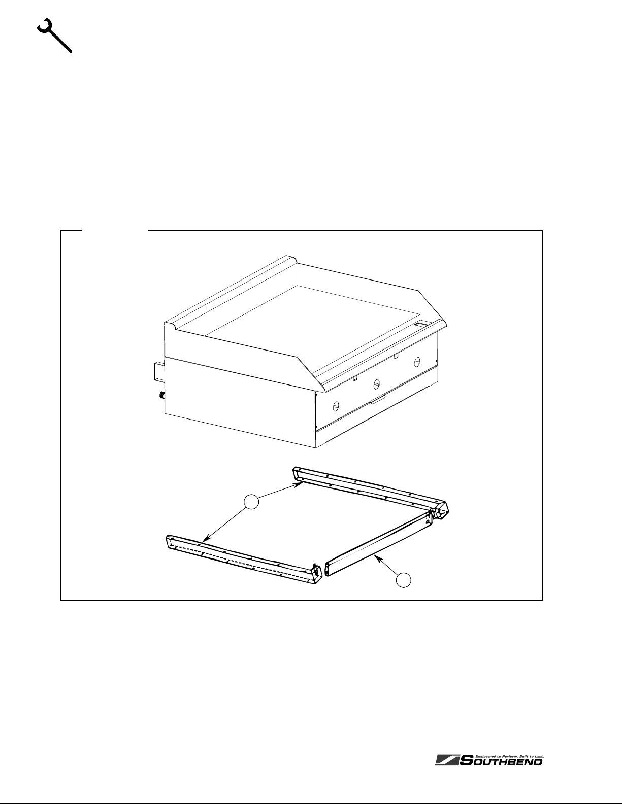
Step 2c: Installation on Insulated Base
The appliance may be installed onto a flat NON-COMBUSTIBLE (but heat sensitive) surface using the
optional insulated base, as follows:
1. Attach the side pieces of the insulated base (items “A” in Figure 7 below) to the front piece (item “B”)
using the four sheet metal screws provided.
2. Position the insulated base on the surface where you want the appliance to be located.
3. Position the appliance on top of the insulated base. Lift the appliance only from the ends, never from
the middle!
4. Go on to Step 4 on page 18.
INSTALLATION
Figure 7
A
B
PAGE 12 OWNER’S MANUAL 1182845 REV 8
Page 13
HEAVY DUTY COUNTERLINE INSTALLATION
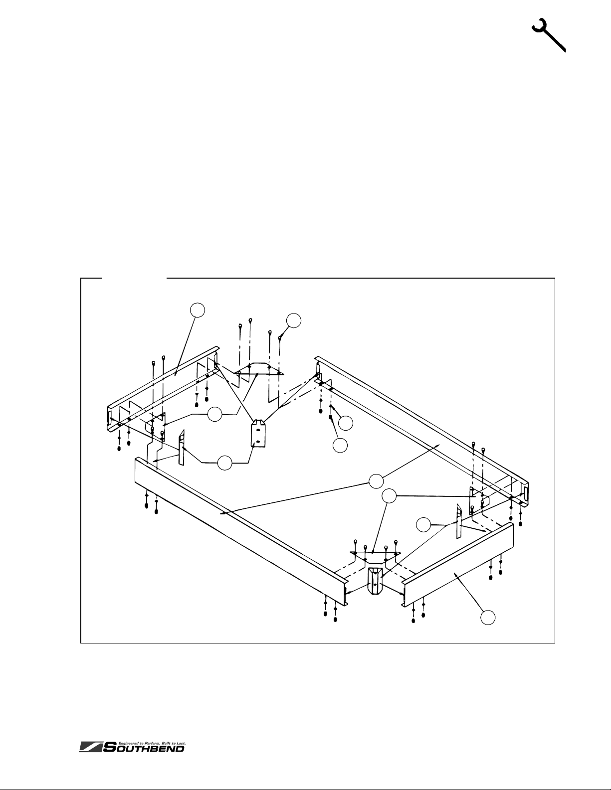
Step 2d: Installation on Floor Stand (24", 36", and 48" Models)
The 24", 36", and 48" appliances may be installed on top of an optional floor stand (for 60" and 72"
griddles, go to Step 2e on page 15). The floor stand is shipped in a separate crate and must be assembled,
as follows:
1. Position the bottom-brace pieces on a flat surface, as shown in Figure 8 below. There are two bottomside braces (items “A”), a bottom-front brace (item “B”), and an identical bottom-rear brace (item “B”).
2. Position a corner brace (item “C”) in each corner, matching the pre-punched holes on the lower inside
flange of the bottom braces.
3. Position a leg bracket (item “D”) into each corner. Be sure that the bracket flanges are engaged into the
open hem of the bottom braces.
4. Use the sixteen 1/2"-long hex head bolts (items “E”), lock washers (items “F”), and acorn nuts (items
“G”) to bolt the corner braces to the bottom braces. Only hand-tighten for now.
5. Check that the leg brackets are in the proper position, and that the outside corners are square.
Figure 8
A
E
INSTALLATION
C
D
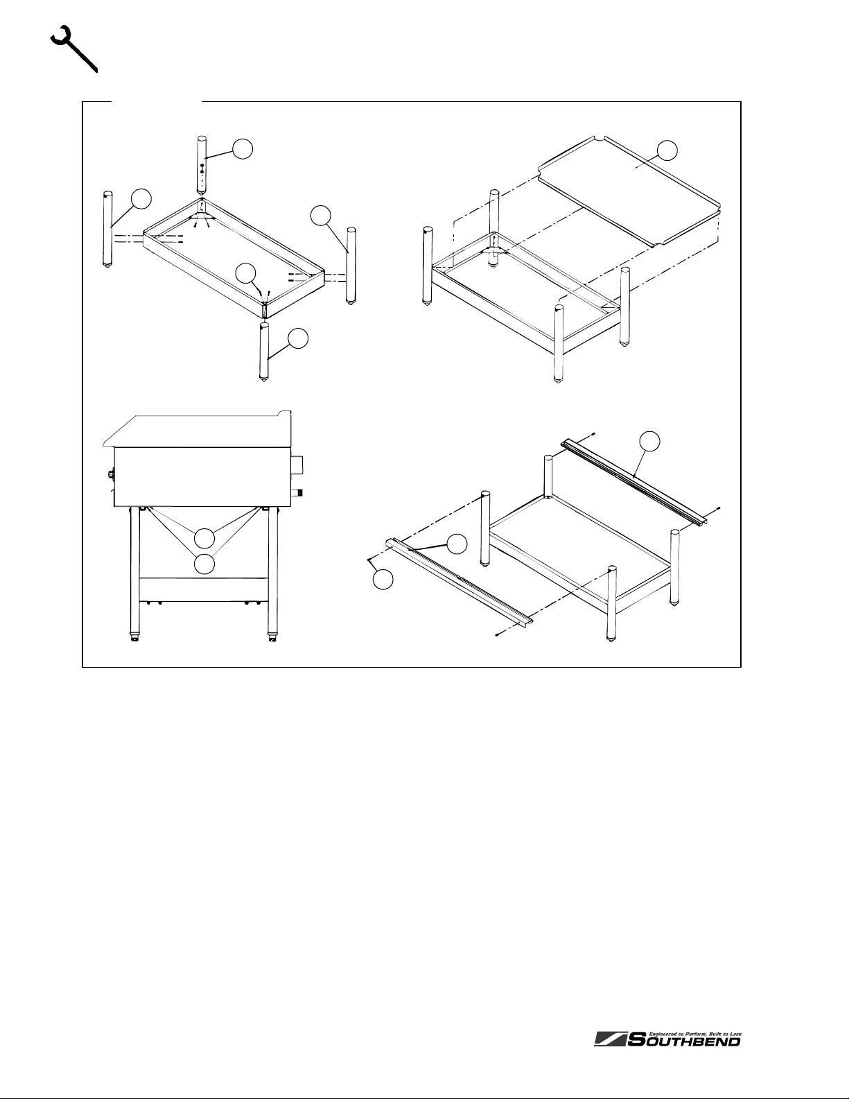
6. Use the eight 1-1/2" hex bolts (items “H” in Figure 9) to attach the two left-legs (items “I”) and the two
right-legs (items “J”). “Left” and “right” are as seen from the front or rear of the stand. Be sure that the
small threaded-insert near the top of each leg faces either the front or the rear of the stand, not a side.
Insert the bolts through the leg brackets and into the legs. Only hand-tighten the bolts for now.
F
G
B
C
D
A
OWNER’S MANUAL 1182845 REV 8PAGE 13
Page 14
INSTALLATION HEAVY DUTY COUNTERLINE
Figure 9
INSTALLATION
J
I
I
H
J
N
O
M
L
K
L
7. Check the partially assembled stand to make sure that the legs are straight and that all corners are
square. Now tighten all bolts, but do not over tighten.
8. If legs with casters were ordered, lift the stand and screw the caster assemblies into the bottom of the
legs. The two casters with wheel-locks go on the front legs. After the stand is assembled, be sure to
connect the required restraint to protect the flexible gas connection (see Step 3 on page 17).
9. If the optional shelf was ordered (item “K”), position it on top of the bottom braces. The down-flange
edge of the shelf should be on the front side of the stand. The shelf simply rests on the bottom braces
(it is not bolted or screwed to the braces).
10. Position the front and rear top supports (items “L”) over the legs. The pre-drilled holes should face the
outside of the stand to line up with the threaded-insert holes near the top of the legs. Use the four 5/8"
hex-head bolts (items “M”) to secure the top supports to the legs.
11. Attach the angle support brackets (item “N”, shipped with the appliance) to the bottom of the of the
appliance using #10x1/2" sheet metal screws (item “O”, also shipped with the appliance).
12. Place the appliance on top of the stand, making sure that the angle brackets that you just installed on
the bottom of the appliance are inserted into the front and rear top supports. No additional bolts or
screws are required. Lift the appliance only at the ends, never in the middle!
13. Go on to Step 4 on page 18.
PAGE 14 OWNER’S MANUAL 1182845 REV 8
Page 15
HEAVY DUTY COUNTERLINE INSTALLATION
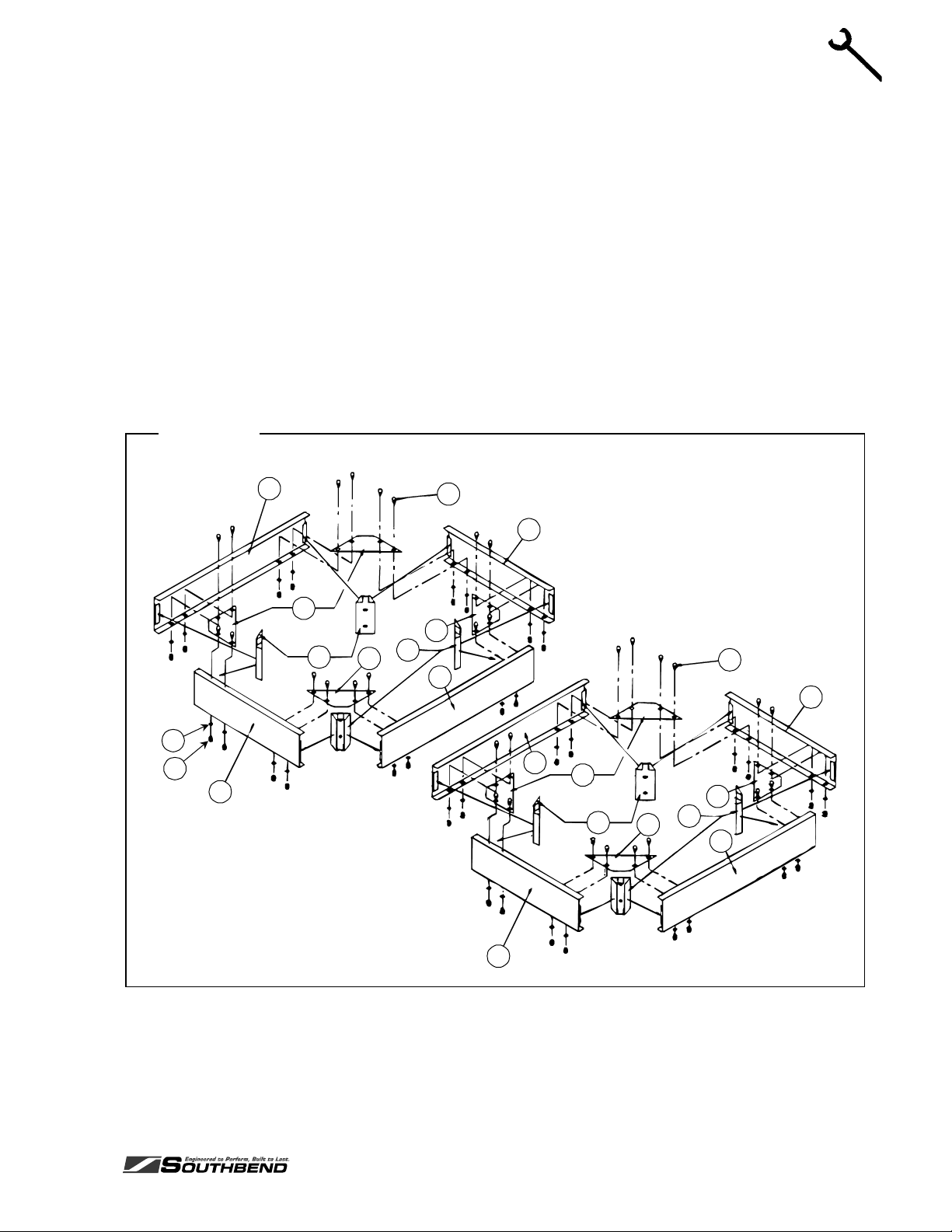
Step 2e: Installation on Floor Stand (60" and 72" Models)
A 60" or 72" griddle may be installed on top of an optional floor stand (for 24", 36", and 48" griddles, go to
Step 2d on page 13). The floor stand is shipped in a separate crate and must be assembled, as follows:
1. Position the bottom-brace pieces on a flat surface, as shown in Figure 10 below. There are four
bottom-side braces (items “A”), and four front/rear bottom-braces (items “B”).
2. Position a corner brace (item “C”) in each interior corner, matching the pre-punched holes on the lower
inside flange of the bottom braces.
3. Position the six leg brackets (item “D”); one in each corner of the stand, one front-center, and one rearcenter, as shown in Figure 10. Be sure that the bracket flanges are engaged into the open hem of the
bottom braces.
4. Use the thirty-two 1/2"-long hex head bolts (items “E”), lock washers (items “F”), and acorn nuts (items
“G”) to bolt the corner braces to the bottom braces. Only hand-tighten for now.
5. Check that the leg brackets are in the proper position, and that the outside corners are square.
Figure 10
A
C
D
C
E
B
C
D
A
E
B
INSTALLATION
F
G
B
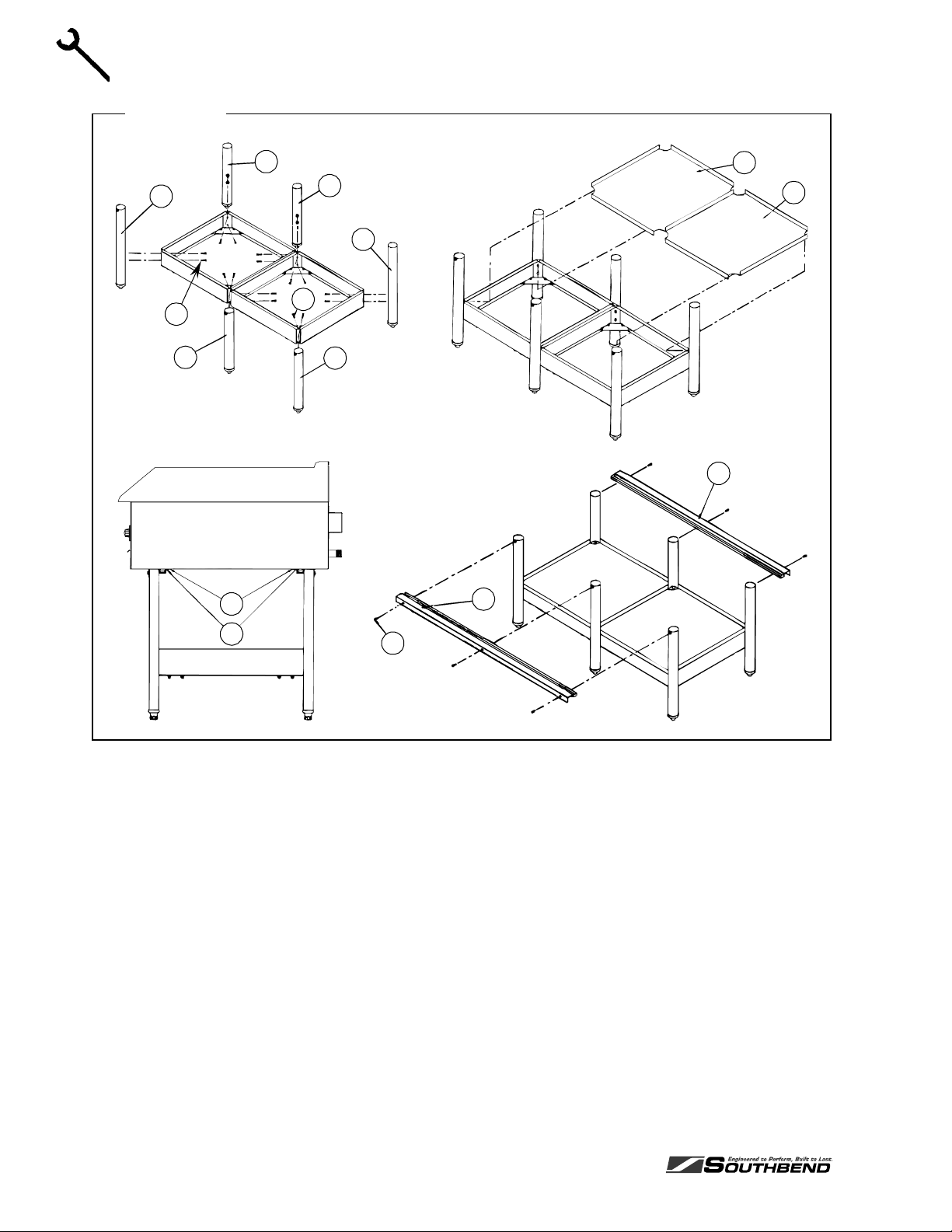
6. Use the twelve 1-1/2" hex bolts (items “H” in Figure 11) to attach the two left-legs (items “I”), the two
right-legs (items “J”), and the two center-legs (items “P”). “Left” and “right” are as seen from the front or
rear of the stand. Be sure that the small threaded-insert near the top of each leg faces either the front
or the rear of the stand, not a side. Insert the bolts through the leg brackets and into the legs. Only
hand-tighten the bolts for now.
OWNER’S MANUAL 1182845 REV 8PAGE 15
A
B
C
C
D
D
C
A
Page 16
INSTALLATION HEAVY DUTY COUNTERLINE
Figure 11
INSTALLATION
J
I
H
P
N
P
I
H
J
L
K
K
L
O
7. Check the partially assembled stand to make sure that the legs are straight and that all corners are
square. Now tighten all bolts, but do not over tighten.
8. If legs with casters were ordered, lift the stand and screw the caster assemblies into the bottom of the
legs. The two casters with wheel-locks go on the front corner legs. After the stand is assembled,
connect the required restraint to protect the flexible gas connection (see Step 3 on pag e 17).
9. If the optional shelves were ordered (items “K”), position them on top of the bottom braces. The downflange edge of each shelf should be on the front side of the stand. The shelves simply rest on the
bottom braces (they are not bolted or screwed to the braces).
10. Position the front and rear top supports (items “L”) over the legs. The pre-drilled holes should face the
outside of the stand to line up with the threaded-insert holes near the top of the legs. Use the six 5/8"
hex-head bolts (items “M”) to secure the top supports to the legs.
11. Attach the angle support brackets (item “N”, shipped with the griddle) to the bottom of the of the griddle
using #10x1/2" sheet metal screws (item “O”, also shipped with the griddle).
12. Place the griddle on top of the stand, making sure that the angle brackets that you just installed on the
bottom of the griddle are inserted into the front and rear top supports. No additional bolts or screws are
required. Lift the griddle only at the ends, never in the middle!
M
13. Go on to Step 4 on page 18.
PAGE 16 OWNER’S MANUAL 1182845 REV 8
Page 17

HEAVY DUTY COUNTERLINE INSTALLATION
Step 3: Attach Restraint for Appliances Mounted on Casters
NOTICE
For an appliance equipped with casters, (1) the installation shall be made with a connector that
complies with the Standard for Connectors for Movable Gas Appliances, ANSI Z21.69 or Connectors
for Moveable Gas Appliances, CAN/CGA-6.16, and a quick-disconnect device that complies with the
Standard for Quick-Disconnect Devices for Use With Gas Fuel, ANSI Z21.41, or Quick Disconnect
Devices for Use with Gas Fuel, CAN1-6.9, (2) adequate means must be provided to limit the
movement of the appliance without depending on the connector and the quick-disconnect device or
its associated piping to limit the appliance movement and (3) the restraining means should be
attached to a frame member on the back of the unit.
! WARNING
To avoid accidental gas disconnection and potential explosion:
If disconnection of this restraint is necessary to move the appliance for cleaning, etc., reconnect it
when the appliance is moved to its originally installed position.
Appliances mounted on a stand with casters or other movable surface must be equipped with a restraining
means to prevent accidental stress on the flexible gas connection.
INSTALLATION
1. Secure the restraining-device bracket (item “B” in the following illustration) to a wall stud located as
close as possible to the appliance connector inlet and outlet connections. Use four #12 screws (items
“C”) and plastic anchors (items “A”) if necessary.
Figure 12
A
D
E
H
F
C
B
G
I
Note: Kit can be purchased from Southbend (part number 1176867).
OWNER’S MANUAL 1182845 REV 8PAGE 17
Page 18

2. Install eye-bolt (item “F”) to a frame member on the rear of the appliance. After checking carefully
behind the frame member for adequate clearance, drill a 1/4" hole through the frame member.
3. Thread hex nut (item “G”) and slide the washer (item “H”) onto the eye-bolt. Insert the eye-bolt through
the 1/4" drilled hole and secure with a washer (item “H”) and nylon lock nut (item “I”).
4. Using the spring-loaded snap hooks, attach the restraining device to the bracket and the eye-bolt.
5. Using the cable clamp (item “D”), adjust the restraining device extended length to prevent over-bending
or kinking of the appliance connector.
Note: For units not equipped with flame safety devices, be sure all valves are turned off prior to
disconnecting. After reconnecting, be sure all valves are turned off and all pilots are lit.
INSTALLATION
Step 4: Connect Gas Supply
The serial plate is located interior side of the control panel (see Figure 1 on page 3). It indicates the type of
gas the appliance is equipped to burn. All Southbend equipment is adjusted at the factory. Check type of
gas on serial plate. This appliance should be connected ONLY to the type of gas for which it is equipped.
If the appliance is being installed at over 2,000 feet altitude and that information was not specified when
ordered, contact the appropriate authorized Southbend Service Representative or the Southbend Service
Department. Failure to install with proper orifice sizing will result in poor performance and may void the
warranty.
INSTALLATION HEAVY DUTY COUNTERLINE
These models are design-certified for operation on natural or propane gases. For natural gas, the
convertible regulator shipped with the appliance is set to deliver a 4" W.C. pressure to the manifold. For
propane gas, it is set to deliver 10" W.C.
An adequate gas supply is imperative. Undersized or low pressure lines will restrict the volume of gas
required for satisfactory performance. Fluctuations of more than 25% on natural gas or 10% on propane
gas will create problems and affect burner operating characteristics. A 1/8" pressure tap is located on the
manifold to measure pressure.
Purge the supply line to clean out dust, dirt, or other foreign matter before connecting the line to the
appliance.
Use pipe joint compound that is suitable for use with LP gas on all threaded connections.
! CAUTION
ALL PIPE JOINTS AND CONNECTIONS MUST BE TESTED THOROUGHLY FOR GAS LEAKS.
USE ONLY SOAPY WATER FOR TESTING ON ALL GASES. NEVER USE AN OPEN FLAME TO
CHECK FOR GAS LEAKS. ALL CONNECTIONS MUST BE CHECKED FOR LEAKS AFTER THE
APPLIANCE HAS BEEN PUT INTO OPERATION. TEST PRESSURE SHOULD NOT EXCEED 14"
W.C.
To connect the gas supply, do the following:
1. Check that the gas supply to the piping that will be connected to the appliance is shut off.
2. Check that the manual shut-off valve inside the front panel door of the appliance is closed (60" and 72"
models have two shut-off valves).
3. Check that all control knobs on the appliance are turned “OFF.”
4. Attach the pressure regulator shipped with the appliance to the 3/4" NPT gas inlet connector located on
the rear of the appliance (see Figure 13 below). Be sure that the regulator is connected so that the gas
flow is in the same direction as the arrow on the bottom of the regulator.
PAGE 18 OWNER’S MANUAL 1182845 REV 8
Page 19

HEAVY DUTY COUNTERLINE INSTALLATION
5. Connect the vent line from the pressure regulator to the outdoors in accordance with local codes or, in
the absence of local codes, with the National Fuel Gas Code, ANSI Z223.1, Natural Gas Installation
Code, CAN/CGA-B149.1, or the Propane Installation Code, CAN/CGA-B149.2, as applicable.
6. Connect the gas inlet of the pressure regulator to the building’s supply system. No segment of the gas
supply connection to the appliance should be smaller than 3/4" NPT. Standard pipe fittings are
required.
7. Turn on gas supply.
8. Check for leaks using soapy water.
Figure 13
Vent tube inc lude d on griddle s
built after June 19, 2006.
INSTALLATION
Step 5: Final Positioning, Clearance Check, and Ventilation Check
1. Position the appliance where it will be operated.
2. Check that the appliance surface is level. The length of each leg is adjustable by screwing the bottom
portion of the leg in or out. The appliance must be level for proper operation!
3. Check for adequate clearances around the appliance (see page 5).
4. Check for adequate ventilation (see page 5).
NOTICE
In the Commonwealth of Massachusetts all gas appliances vented by either mechanical systems or
ventilation hoods shall comply with 248 CMR interlocking requirements.
Step 6: Check Pilot and Burner Operation
All appliances are adjusted at the factory. However, pilot heights, burner air shutters, and thermostatic
valves should be checked at installation and adjusted if necessary. Do the following:
1. Turn main gas supply “ON”.
2. Check the manifold gas pressure using the procedure on page 28.
3. Light the pilots as described in the Operation section of this manual.
4. Check (and, if necessary, adjust) the pilot flame heights using the procedure on page 29.
OWNER’S MANUAL 1182845 REV 8PAGE 19
Page 20

INSTALLATION HEAVY DUTY COUNTERLINE
5. Light the burners. Set the control knobs to only low temperatures for now.
6. Check (and, if necessary, adjust) the burner air shutters using the procedure on page 29.
Step 7: Final Installation Steps for Griddle Models
This step applies only to the installation of griddle models. New griddles should be carefully tempered and
cared for in order to avoid possible damage. To break in a new griddle, do the following:
1. Wipe the griddle surface clean.
2. Light all the griddle burners. For griddles with thermostatic controls, turn all knobs to 200°F for one
hour. For griddles with manual controls, turn all knobs to “LOW” for one hour. Then gradually bring
each griddle up to frying temperature.
INSTALLATION
3. Spread three or four ounces of beef suet, or as a substitute, baking soda, to season it. Never allow
water on a hot griddle and never wash it with soap and water.
4. For griddles with thermostatic controls, check (and, if necessary, adjust) the thermostatic valves that
control the griddle’s surface temperature. Follow the procedure on page 31.
Step 8: Final Installation Steps for Lava-Rock Charbroilers
This step applies only to the installation of lava-rock charbroiler models. Such models are shipped with the
lava-rock briquettes in bags located between the lava-rock grates and the top cooking grids.
1. Lift out the cooking grids to reach the bags of lava-rock briquettes.
2. For each section, open the bag of lava-rock briquettes and spread them evenly on the lava-rock grate.
The briquettes must be spread evenly to avoid “hot spots.” Discard the empty bags.
3. Reposition the cooking grids above the briquettes.
PAGE 20 OWNER’S MANUAL 1182845 REV 8
Page 21

HEAVY DUTY COUNTERLINE OPERATION
OPERATION
! DANGER
EXPLOSION HAZARD
Purchaser of equipment must post in a prominent location, detailed instructions to be followed in the
event the operator smells gas. Obtain the instructions from the local gas supplier.
! CAUTION
To eliminate gas build up which could result in an explosion, in the event of main burner ignition
failure a five minute purge period must be observed prior to re-establishing ignition source.
! CAUTION
Top section pilots, when out, do not interrupt the flow of gas to the burners. Consequently, it is the
responsibility of the operator to check the ignition of the burners, immediately after burner value has
been turned “ON.” Should ignition fail after 10 seconds, turn off burners, wait 5 minutes, and then try
again.
! WARNING
UNDER NO CIRCUMSTANCES IS A GRIDDLE TO BE USED FOR HEATING STOCK POTS. SUCH
USE AUTOMATICALLY VOIDS THE WARRANTY.
NEVER COOL A GRIDDLE BY APPLYING ICE OR WATER TO THE GRIDDLE SURFACE.
DAMAGE DUE TO MISUSE IS NOT COVERED BY THE WARRANTY.
DO NOT STRIKE A GRIDDLE SURFACE WITH THE EDGE OF COOKING IMPLEMENTS TO
CLEAN THE IMPLEMENTS. SUCH ACTION WILL CUT AND PIT THE GRIDDLE PLATE, LEAVING
IT ROUGH AND HARD TO CLEAN.
ALWAYS HEAT A GRIDDLE SLOWLY. DO NOT HEAT A GRIDDLE ABOVE 550°F.
OPERATION
LIGHTING AFTER GAS HAS BEEN SHUT OFF
When turning the main gas supply on after the gas supply has been shut off, do the following:
1. Make sure all of the control valves are in the “OFF” position.
2. Turn on the gas supply.
3. Light the pilots as described in each section below.
OWNER’S MANUAL 1182845 REV 8PAGE 21
Page 22

OPERATION OF THERMOSTATIC GRIDDLE MODELS
Each 12"-wide griddle section has a thermostatic-control knob on the front panel that directly controls the
flow of gas, and so the heat. Turn the knob clockwise to increase the heat; turn it counterclockwise to
reduce the heat.
The griddle requires approximately 13 minutes of preheating to reach 350°F, and 45 minutes to even out.
Do not waste gas or abuse equipment by leaving control knobs set at a high temperature if not required.
During idle periods, set control knobs to low temperature settings to keep griddle wa rm.
After each period of use, allow the griddle surface to cool normally. At the end of each day’s use, turn all
control knobs to the “OFF” position. After the griddle has cooled, coat the griddle surface with a light film of
cooking oil to protect the surface from moisture.
To shut down the appliance for an extended period (or before disconnecting the gas supply), turn all the
burner control gas knobs “OFF,” then turn the main gas supply valve(s) to “OFF.”
To light the pilots of a thermostatic griddle section, do the following:
1. Turn all griddle controls to the “OFF” position.
2. Open the grease/control door at the bottom of the front of the griddle.
3. Turn the main shut-off valve to the “ON” position (if it is not already ON). (Note that 60" and 72" models
OPERATION
4. Note that the left pilot must be lit before the right pilot can be lit. For each pilot, press and hold the
OPERATION HEAVY DUTY COUNTERLINE
have two shut-off values, one in each burner compartment.)
red pilot button and light the pilot by pressing the electronic ignition button on the front panel to
generate a spark. Continue to hold the pilot button for 45 seconds, or until the pilot remains lit. Note
that 24" models have one pilot, 36" & 48" models have two pilots, 60" models have three pilots, and 72"
models have four pilots.
5. If a pilot is extinguished or the gas supply is interrupted, wait five minutes and repeat the above steps.
6. Allow the pilots to warm-up for 1 minute, then turn all griddle thermostat controls to the “ON” position to
check that the pilots will ignite the burners.
Figure 14
This drawing shows a Model HDG-36 with the front panels removed to show the interior parts.
Left Pilot
MainShut-Off
Valve
Note: 24" modelshave one pilot, 36" and 48" models have two pilots, 60"models have three pilots, and 72" models have four pilots.
60" and 72" models havetwo shut-off valves, one in each burner compartment .
Left Pilot
Button
Right Pilot Button
(36" & 48" Models)
Right Pilot
(36" & 48" Models)
Grease Drawer
PAGE 22 OWNER’S MANUAL 1182845 REV 8
Page 23

HEAVY DUTY COUNTERLINE OPERATION
OPERATION OF MANUAL GRIDDLE MODELS
Each 12"-wide griddle section has a knob on the front panel that directly controls the flow of gas, and so the
heat. Turn the knob clockwise to increase the heat; turn it counterclockwise to reduce the heat.
After each period of use, allow the griddle surface to cool normally. At the end of each day’s use, turn all
control knobs to the “OFF” position. After the griddle has cooled, coat the griddle surface with a light film of
cooking oil to protect the surface from moisture.
To shut down the appliance for an extended period (or before disconnecting the gas supply), turn all the
burner control gas knobs “OFF,” then turn the main gas supply valve(s) to “OFF.”
To light the pilots of a manual griddle section, do the following:
1. Turn all griddle controls to the “OFF” position.
2. Light the pilot tube located next to each burner. The pilot flame can be adjusted by turning the screw on
the end of the pilot fitting.
3. Turn burner knobs to “HI” position. The burners should have a 1/2" to 5/8" steady blue flame. Adjust if
necessary.
4. To turn burners off, turn knob to “OFF” position.
Figure 15
OPERATION
The pilots can be viewed and lit through openings on the
front panel (Model HDG-36-M shown).
The drawing below shows a Model HDG-36-M with the front panels removed to show the interior parts.
Left Pilot
Note: 24" modelshave one pilot, 36" and 48" models have two pilots,60" models have three pilots, and 72" models have four pilots.
Right Pilot
(36" & 48" Models)
OWNER’S MANUAL 1182845 REV 8PAGE 23
Page 24

OPERATION OF CHARBROILER MODELS
Each 6"-wide charbroiler section has a knob on the front panel that directly controls the flow of gas, and so
the heat. Turn the knob counterclockwise to increase the heat; turn it clockwise to reduce the heat.
To use the charbroiler, turn all the control knobs to the full “ON” position. (If any burners do not light, check
the pilots and, if necessary, light the pilots as described later in this section.) After 15 to 20 minutes turn
back the flame to maintain enough heat to keep the bottom of the radiants or lava-rock grates hot. The
radiants or grates will be at broiling temperature throughout, providing the radiant heat that is essential to
provide fast broiling.
By design, the rear two-thirds of the broiler grid is much hotter than the front third. Use the rear of the
charbroiler to quickly sear both sides of meat to retain maximum juices. This fast cooking is one of the
secrets of successful meat broiling, and gives the meat that special “outdoor” flavor. Cook rare meats at the
back quickly; cook medium and well-done meats closer to the front more slowly. Adjust the cooking time
according to the thickness of the meat and amount of doneness desired. If desired, move meat cooked rare
to the very front to keep it warm while medium and well-done meats are still cooking. Remember that to
cook meat properly you must keep in mind both heat and time.
The tilt angle of the charbroiler grid is adjustable by pulling up on the back of the grid. The tilted position is
normal and recommended. The tilt angle allows most fat rendered off meat during broiling to run into the
grease trough, thus eliminating excess flaring of fats and accompanying smoke. Steaks and chops, being
fattier than other meats, will still have some flaring up to give the desired broiling results while enough fat
OPERATION
drains off to avoid severe flares. Use the flat position for heating on the top, or for continuous cooking of hot
dogs and sausage. Fats dripping down into the fire will burn up on the meat to help give it that desirable
special flavor.
OPERATION HEAVY DUTY COUNTERLINE
The heavy cast iron grids can be turned over for different “branding” width. One side has wide-branding
(1/4") and the other side has narrow branding (1/8" with grease channel). Chrome-plated grids can be
ordered for cooking fish.
At the end of each day’s use, turn all knobs to the “OFF” position.
To shut down the appliance for an extended period (or before disconnecting the gas supply), turn all the
burner control gas knobs “OFF,” then turn the main gas supply valve to “OFF.”
To light the pilot(s) of a charbroiler section, do the following:
1. Turn all control knobs to the “OFF” position.
2. Light the pilot located next to each burner (accessed through front). If the pilot will not remain lit, have a
service technician adjust the pilot by turning the screw on the pilot fitting.
3. Turn burner knobs to “HI” position. The burners should have a 1/2" to 5/8" steady blue flame. If they do
not, have them adjusted by a service technician.
4. To turn burners off, turn knob to “OFF” position.
PAGE 24 OWNER’S MANUAL 1182845 REV 8
Page 25

HEAVY DUTY COUNTERLINE OPERATION
OPERATION OF OPEN-TOP BURNER MODELS
Each 12"-wide open-top burner section has two knobs on the front panel that directly control the flow of gas
to the section’s two burners, and so control the heat. Turn a knob clockwise to increase the heat; turn it
counterclockwise to reduce the heat.
If any burners do not light, check the pilots and, if necessary, light the pilots as described later in this
section.
At the end of each day’s use, turn all knobs to the “OFF” position.
To shut down the appliance for an extended period (or before disconnecting the gas supply), turn all the
burner control gas knobs “OFF,” then turn the main gas supply valve to “OFF.”
To light the pilots of an open-top burner section, do the following:
1. Turn all gas valves to the “OFF” position.
2. Check to make sure pilots are in the correct position.
3. Light the pilots. If the pilots will not remain lit, have a service technician adjust them.
4. Turn burner knobs to “HI” position. Each burner flame should be steady blue and impinge on the
underside of a pot placed on the support grate. If necessary, have a service technician adjust the
burners.
5. To turn burners off, turn knob to “OFF” position.
OPERATION
OWNER’S MANUAL 1182845 REV 8PAGE 25
Page 26

CLEANING HEAVY DUTY COUNTERLINE
CLEANING
Southbend equipment is constructed with the best quality materials and is designed to provide durable
service when properly maintained. To expect the best performance, your equipment must be maintained in
good condition and cleaned daily. Naturally, the frequency and extent of cleaning depends on the amount
and degree of usage.
Daily:
• Remove, empty, and clean grease drawers of griddles and charbroilers.
• Clean griddle drain chutes of griddles.
Monthly:
• Clean around burner air mixers and orifices if lint has accumulated.
• Visually assure proper pilot operation.
CARE OF CARBON STEEL GRIDDLE SURFACE
Never allow water on a hot griddle and never wash it with soap and water.
Use a Norton Alundum Griddle Brick to clean the griddle. Always remember to heat a griddle slowly
because quick heat may cause costly damage. Griddle plates cannot be guaranteed against damage due
to carelessness. Never place utensils on griddle. Do not overheat griddle above 550°F as this will cause
CLEANING
warpage or breakage.
Do not use any type of steel wool. Small particles may be left on the surface and get into food products. Do
not clean a spatula by hitting the edge on the griddle plate. Such action will only cut and pit the griddle
plate, leaving it rough and hard to clean.
CARE OF CHROME PLATED GRIDDLE SURFACE
Allow griddle plate to cool down to approximately 200°F. Pour 8 ounces of water onto griddle surface.
Apply a non-abrasive degreaser to water on griddle surface. Using a non-abrasive brush, evenly spread
degreaser solution around entire griddle plate surface and use additional water if necessary to cover entire
griddle plate. Allow time to soak until grease begins to separate. Using a non-metallic scraper, remove
remaining grease particles from the griddle surface. Flush the entire griddle surface with clean water until
all degreaser solution has been removed. Wipe he entire griddle surface, back and splash walls with a
clean damp cloth.
CARE OF STAINLESS STEEL SURFACES
To remove normal dirt, grease and food residue from stainless steel that operates at LOW temperature,
use ordinary soap and water (with or without detergent) applied with a sponge or cloth. Dry thoroughly with
a clean cloth.
To remove grease, food splatter, or condensed vapors that have BAKED onto the equipment, apply
cleanser to a damp cloth or sponge and rub cleanser on the metal in the direction of the polishing lines on
PAGE 26 OWNER’S MANUAL 1182845 REV 8
Page 27

HEAVY DUTY COUNTERLINE CLEANING
the metal. Rubbing cleanser, as gently as possible, in the direction of the polished lines will not mar the
finish of the stainless steel. NEVER RUB WITH A CIRCULAR MOTION. Soil and burnt deposits which do
not respond to the above procedure can usually be removed by rubbing the surface with SCOTCH-BRITE
scouring pads or STAINLESS scouring pads. DO NOT USE ORDINARY STEEL WOOL, as any particles
left on the surface will rust and further spoil the appearance of the finish. NEVER USE A WIRE BRUSH,
STEEL SCOURING PADS (EXCEPT STAINLESS), SCRAPER, FILE OR OTHER STEEL TOOLS.
Surfaces that are marred collect dirt more rapidly and become more difficult to clean. Marring also
increases the possibility of corrosive attack. Refinishing may then be required.
“Heat tint” is a darkened area that can appear on a stainless steel surface where the area has been
subjected to excessive heat. These darkened areas are caused by thickening of the protective surface of
the stainless steel and are not harmful. Heat tint can normally be removed by the foregoing, but tint which
does not respond to this procedure calls for a vigorous scouring in the direction of the polish lines, using
SCOTCH-BRITE scouring pads or a STAINLESS scouring pad in combination with a powered cleanser.
Heat tint action may be lessened by not applying, or by reducing heat to equipment during slack periods.
CLEANING
OWNER’S MANUAL 1182845 REV 8PAGE 27
Page 28

ADJUSTMENTS HEAVY DUTY COUNTERLINE
ADJUSTMENTS
! WARNING
ADJUSTMENTS AND SERVICE WORK MAY BE PERFORMED ONLY BY A QUALIFIED
TECHNICIAN WHO IS EXPERIENCED IN, AND KNOWLEDGEABLE WITH, THE OPERATION OF
COMMERCIAL COOKING EQUIPMENT. HOWEVER, TO ASSURE YOUR CONFIDENCE,
CONTACT YOUR AUTHORIZED SERVICE AGENCY FOR RELIABLE SERVICE, DEPENDABLE
ADVICE OR OTHER ASSISTANCE, AND FOR GENUINE FACTORY PARTS.
NOTICE
The warranty will be void and the manufacturer relieved of all responsibility if…
(A) Service work is performed by other than a qualified technician, or
(B) Other than genuine Southbend replacement parts are installed.
Before making any adjustment, make sure the appliance is connected to the type of gas for which it is
equipped. That information is on the serial plate, which is located on the inside of the control panel (see
Figure 1 on page 3).
ADJUSTMENT OF MANIFOLD GAS PRESSURE
A pressure regulator is connected to the appliance’s gas connection, outside the rear left corner of the
appliance. The pressure regulator is factory set at 4" W.C. for natural gas and 10" W.C. for propane. To
check the manifold pressure, do the following:
1. Turn all burner valves to “OFF” position.
2. Turn main gas valve to entire appliance off.
3. Remove front panel and locate 1/8" plug in manifold. (Note that 60" and 72" griddle models have two
burner compartments, and so have two manifolds.)
ADJUSTMENTS
4. Remove the plug and install a fitting appropriate to connect a manometer.
5. Turn on main gas to appliance and light pilots.
6. Turn all burners to full “ON” position and read manometer.
7. If manometer does not read 4" W.C. for natural gas (or 10" W.C. for propane gas), check the incoming
gas line for proper pressure. The proper gas line pressure is 5-7" W.C. for natural gas and 11-14" W.C.
for propane.
8. Remove manometer fitting and replace plug in manifold.
9. Replace front panel.
10. Turn on main gas to appliance and light pilots.
PAGE 28 OWNER’S MANUAL 1182845 REV 8
Page 29

HEAVY DUTY COUNTERLINE ADJUSTMENTS
A
ADJUSTMENT OF PILOT FLAME (GRIDDLE MODELS)
The pilots are adjusted at the factory. If later the pilots are over-adjusted to the point where the flame is
leaving its port, or “blowing off,” the result is an unstable condition in which the pilot may extinguish. If
necessary, adjust each burner’s pilot using the following procedure:
1. Open the door on the lower front of the appliance, remove the control knobs, and remove the control
panel by removing the screws holding it in place.
2. If necessary, light the pilots.
3. Locate the adjustment valve of the pilot that needs adjustment (see Figure 16 below). On thermostatic
griddles, the valve is in the pilot’s supply line, while on manual griddles the valve connects the pilot’s
supply line to the front manifold. Turn the pilot adjustment screw to the left to increase the size of the
pilot flame, or to the right to decrease the size of the pilot flame. The flame should be about 1/2" high
with a slight yellow tip, and cover the thermocouple tip. The flame is too high if the yellow tip is
producing black streaks of carbon.
4. Repeat Step 3 for each pilot.
5. Replace the control panel and knobs.
Figure 16
Pilot Flame Adjustment Screw
on Thermostatic Griddles
Pilot Flame Adjustment Screw
on Manual Griddles
ADJUSTMENT OF PILOT FLAME (CHARBROILER AND OPEN-TOP MODELS)
The pilots are adjusted at the factory. If later the pilots are over-adjusted to the point where the flame is
leaving its port, or “blowing off,” the result is an unstable condition in which the pilot may extinguish. If
necessary, adjust each burner’s pilot using the following procedure:
1. If necessary, light the pilots.
2. Locate the pilot adjustment valve (see Figure 17 below). Turn the pilot adjustment screw to the left to
increase the size of the pilot flame, or to the right to decrease the size of the pilot flame. The flame
should be about 1/2" high with a slight yellow tip. The maximum pilot flame height is 3/4". The flame is
too high if the yellow tip is producing black streaks of carbon.
4. Repeat Step 3 for each pilot.
5. Replace the control panel and knobs.
Figure 17
ADJUSTMENTS
Pilot Flame
djustment Screws
OWNER’S MANUAL 1182845 REV 8PAGE 29
Page 30

ADJUSTMENTS HEAVY DUTY COUNTERLINE
ADJUSTMENT OF BURNER FLAME
The burners are adjusted at the factory. If necessary to adjust the burner flames, do the following for each
burner:
1. Turn the burner’s control knob to the full ON position.
2. If the appliance was cold, wait 5 minutes before adjusting the burner flame.
3. Loosen the set screw that holds the sheet-metal air shutter in place.
4. If the burner flame is blowing or lifting off the burner ports, close the air shutter until a stable flame is
obtained. If the flame is yellow-tipping, open the air shutter until a stable blue flame is obtained (a small
amount of yellow-tipping is normal when using propane gas).
5. Tighten the set screw that holds the sheet-metal air shutter in place.
6. Repeat Steps 1 through 5 for each burner.
When adjusting the burners of griddle models, note that over-gassed burners DO NOT heat griddles as
efficiently as those that are properly adjusted and also create “hot spots” on the griddle surface. Floating
and unstable burner and pilot flames will result when solid tops are lowered into position because the rear
openings of the burner compartment are not adequate to vent the enormous flue products generated by
over-gassed burners. The “unburned” gas will ignite at the rear and burn in this section and even up inside
the backguard or shelf venting system, causing structural members in this area to deteriorate. Also, some
of these hot flue products will vent forward into the manifold compartment resulting in problems with valves
and thermostats due to overheating. AGAIN, over-rated burners waste energy and cause service problems.
CONVERSION FROM ONE TYPE OF GAS TO ANOTHER
Each appliance is shipped gas-specific either for use with natural gas or for use with LP gas (propane). To
convert an appliance from one type of gas to another, do the following:
1. Remove the front panel by removing the knobs and screws on the front.
2. For each burner, replace the orifice with the type appropriate for the type of gas that will be used. For
special gas mixtures, and for altitudes above 2,000 feet, consult factory for appropriate orifice sizes.
3. For griddle models only, replace all the pilot assemblies.
4. Re-install the front panel.
5. Remove the hex-threaded plug from the pressure regulator (on the rear of the appliance). Inside is a
removable insert. Pull the insert out, turn it around, and put it back in so that the end facing out has the
ADJUSTMENTS
letters corresponding to the type of gas that will be used (“NAT” or “LP”). Re-attach the hex-threaded
plug.
6. Check the manifold pressure (the procedure is on page 28).
Note: A kit for conversion to a different type of gas may be purchased from Southbend.
PAGE 30 OWNER’S MANUAL 1182845 REV 8
Page 31

HEAVY DUTY COUNTERLINE ADJUSTMENTS
ADJUSTMENT OF GRIDDLE THERMOSTATS
Each burner’s control knob operates a snap-action thermostatic valve that was adjusted at the factory. If
the griddle surface temperature is different from the thermostat dial setting, adjust the valve using the
following procedure:
1. Turn all the control knobs to the 300°F.
2. Wait 30 minutes (or 1 hour if the griddle was cold).
3. Place a reliable thermometer or test-instrument thermocouple (able to register 300°F) halfway back
from the front to the back of the griddle and directly over a burner (in line with the burner’s control knob,
see Figure 18 below). Check the temperature over each burner every five minutes until the temperature
over each burner stabilizes and does not change by more than 30°F between two consecutive
measurements.
4. If the average temperature over any burner is not within 30°F of the knob setting (300°F), adjust the
corresponding thermostatic valve. To do so, remove the knobs and control panel, adjust the calibration
screw on the thermostatic valve (see Figure 18 below), replace the knobs and control panel, then
repeat Step 3.
Figure 18
Measure each temperature
halfway back from front to
back and directly over the
corresponding burner (in line
with the control knob).
Calibrate the valve using the Thermostat Calibration
Screw located at the base of the stem. Turn the
screw counterclockwise to increase the temperature,
or clockwise to decrease the temperature.
ADJUSTMENTS
OWNER’S MANUAL 1182845 REV 8PAGE 31
Page 32

TROUBLESHOOTING HEAVY DUTY COUNTERLINE
TROUBLESHOOTING
Consult the following table for troubleshooting guidance.
Problem Look for -
No burners or pilots will turn on – Main gas supply to unit is “OFF”
Problem with a particular burner
Griddle will not heat up – Main gas supply to griddle is “OFF”
Lava-rock charbroiler has “hot spots” – Stacked-up lava-rock briquettes (briquettes should be
Burners produce excessive carbon deposits – Incorrect gas type
Pilot produces excessive carbon deposits
Pilot will not stay lit – Pilot not adjusted properly
– Valve for that burner in “OFF” position
– Pilot out
– Burner not level in support brackets
– Clogged burner ports
– Clogged burner venturi
– Clogged burner orifice
– Wrong type of burner orifice
– Burner orifice out of alignment with burner
– Pilot(s) not lit
– Fault in thermostat(s)
– Clogged orifice or burner ports
spread out evenly)
– Incorrect orifice size
– Incorrect supply pressure
– Incorrect burner air mixer adjustment
– Burner orifice out of alignment with burner
– Pilot gas not adjusted properly
– Incorrect pilot orifice
– Clogged or dirty orifice
– Draft condition
– Improper ventilation system
– Air in gas line
– Valve end of thermocouple corroded or loose
– Pilot shield needs to be moved closer to pilot
– Improper gas pressure
– Incorrect gas supply size (not enough volume)
– Fault in thermocouple
Burner makes a slight popping noise when turned off – This is normal when using propane gas
Electronic ignition module will not generate a spark
TROUBLESHOOTING
PAGE 32 OWNER’S MANUAL 1182845 REV 8
– Dead battery in ignition module
– Fault in spark module
– Fault in switch
Page 33

HEAVY DUTY COUNTERLINE PARTS
PARTS
NOTICE
INSTALLATION OF OTHER THAN GENUINE SOUTHBEND PARTS WILL VOID THE WARRANTY
ON THIS EQUIPMENT.
The serial plate is located inside of the control panel on the front of the appliance (see Figure 1 on page 3).
Replacement parts may be ordered either through a Southbend Authorized Parts Distributor or a
Southbend Authorized Service Agency.
When ordering parts, please supply the Model Number, Serial Number, Part Number, and Description.
For parts not listed, consult a Southbend Authorized Parts Distributor or Southbend Authorized Service
Agency. Consult the Southbend Authorized Parts/Service Distributor list for the Authorized Parts supplier in
your area. If this list is not available, call Southbend at 1-800-348-2558 to obtain this list.
Except where a part number is explicitly associated with a particular model number, all parts listed are used
by all the models covered by this manual. (On griddle models, an “RE” suffix on the model number
indicates that the model has a rear trough, while an “M” suffix is indicates that it has manual temperature
controls. On open-top models, an “SU” suffix on the model number indicates that it is a “step-up” model
with the rear burners higher than the front burners.)
Index of Parts Diagrams
Page Number Description
34 Griddle Chassis Parts
36 Thermostatic Griddle Gas System Parts
38 Manual Griddle Gas System Parts
40 Charbroiler Parts
42 Open Top Parts
44 Floor Stand Parts for 24", 36", and 48" Width Units
46 Floor Stand Parts for 60" Width Units
48 Countertop Legs and Insulated-Base Parts
OWNER’S MANUAL 1182845 REV 8PAGE 33
PARTS
Page 34

PARTS HEAVY DUTY COUNTERLINE
Griddle Chassis Parts
See drawing on following page.
Quantity for Griddle Width
Key Part Number
1 1182586 23456Knob (for thermostatic griddles)
1177704 23456Knob (for manual griddles)
2 1182612 1 - - 1 - Door w eld assembly, 24"
1182620 - 1 - 1 2 Door weld assembly, 36"
1182624 - - 1 - - Door weld assembly, 48"
** 1182637 11122Magnetic Catch(for units built before April 10, 2001)
1182847 11122Compression Ball Latch(for units built after April 10, 2001)
3 1182618 1 - - 1 - Control panel, 24"
1182552 - 1 - 1 2 Control panel, 36"
1182627 - - 1 - - Control panel, 48"
** 1180145 1 - - 1 - Polypanel, 24"(for units built before November 3 , 2000)
1183365 1 - - 1 - Poly panel, 24"(for units built after November 3, 2000)
1182631 - 1 - 1 2 Polypanel, 36" ( for units built before November 3, 2000)
1182760 - 1 - 1 2 Polypanel, 36"( for units built after N ovember 3, 2000)
1182632 - - 1 - - Polypanel, 48"(f or units built before Nov ember 3, 2000)
1182632 - - 1 - - Polypanel, 48"(f or units built after November 3, 2000)
4 1182558 22244Hinge bracket
5 1182592 11122Hinge, male, left
6 1182591 11122Hinge, male, right
7 1182604 11111Grease drawer weld assembly
8 1182588 11122Drawer guide (for units built before November 13, 2006)
1189069 11122Drawer cover (for units built after November 13, 2006)
9 1182160 12234Pilot assembly bracket (for units built before January 8, 2007)
1189235 12234Pilot assembly bracket (for units built after January 8, 2007)
10 1183361 23456Bulb cover weld assembly
11 1182611 1 ----Smooth-griddle weld assembly, 24" * (for units built before November 3, 2000)
1183383-01 1 ----Smooth-griddle weld assembly, 24" * (for units built after November 3, 2000)
1182608 - 1 - - - Smooth-griddle weld assembly, 36" * ( for units built before November 3, 2000)
1183384-01 - 1 - - - Smooth-gridd le weld assembly, 36" * (for units built after November 3, 20 00)
1182609 - - 1 - - Smooth-griddle weld assembly, 48" * (for units built before November 3, 2000)
1183385-01 - - 1 - - Smooth-gridd le weld assembly, 48" * (for units built after November 3, 20 00)
1182605 - - - 1 - Smooth-griddle weld assembly, 60" * (for units built before November 3, 2000)
1183386-01 - - - 1 - Smooth-gridd le weld assembly, 60" * (for units built after November 3, 20 00)
1187911-01 ----1Smooth-griddle weld assembly, 72"
12 1182554 12334Burner divider
13 1180299 22244Bracket, standoff
* Contact Southbend to obtain part numbers for optional groov e d-gridd l e as s embli es .
** Not shown on drawing.
24"36"48"60"72
Description
"
PARTS
PAGE 34 OWNER’S MANUAL 1182845 REV 8
Page 35

HEAVY DUTY COUNTERLINE PARTS
Griddle Chassis Parts
See parts list on previous page. Model HDG-24 is shown.
11
10
12
13
5
3
2
4
89
1
7
6
PARTS
OWNER’S MANUAL 1182845 REV 8PAGE 35
Page 36

PARTS HEAVY DUTY COUNTERLINE
Thermostatic Griddle Gas System Parts
See drawing on following page.
Key Part Number
11182564 11122Supply pipe bracket weld assembly
2P5244-4 11122Pipe reducer
3P9158 22244Connector, brass, 68C-10-8
41182566 11122Tube, 5/8" supply
51160008 22244Elbow, brass
61-5771 11122Valve, shut off, 1/2"
71146806 11122Nipple, pipe, close, black, 1/2"
8 1182594 1 - - 1 - Safety valve, single
1182567 -1112Safety valve, dual
*1182580 1111-Thermocouple 24”
1182565 -1112Thermocouple 36”
9 1182633 1 - - 1 - Tube, loop to safety, single
1182638 -1112Tube, loop to safety, dual
101182562 11122Elbow bracket weld assembly
11 1182574 1 - - 1 - 24" manifold weld assembly
1182560 - 1 - 1 2 36" manifold weld assembly
1182571 - - 1 - - 48" manifold weld assembly
121166150 23456Male elbow
131181499 23456Tubing, 3/8 x 1.750
141182553 23456Valve assembly, thermostat
*1057200 23456Orifice fitting
*1008732 23456Orifice NAT gas (for units built before November 3, 2000)
1183381 23456Orifice NAT gas (for units built after November 3, 2000)
*1008752 23456Orifice LP gas (for units built before November 3, 2000)
1183372 23456Orifice LP gas (for units built after November 3, 2000)
151182610 23456Burner weld assembly SGS (for units built before November 3, 2000)
1183371 23456Burner weld assembly SGS (for units built after November 3, 2000)
161182639 11122Pilot tube left (for units built before January 8, 2007)
1188979 11122Pilot tube left (for units built after January 8, 2007)
171164085 12234Valve assembly, pilot (for units built before January 8, 2007)
1189063 12234Valve assembly, pilot (for units built after January 8, 2007)
18 1182641 - 1 - 1 2 Tube, pilot 36" right
1182642 - - 1 - - Tube, pilot 48" right
191182640 12234Tube, pilot (for units built before November 3, 2000)
1182161 12234Tube, pilot extension (for units built between November 3, 2000 and January 8, 2007)
1188977 12234Tube, flex 12" (for units built after January 8, 2007)
201182635 12234Pilot assembly (for LP gas units built before January 8, 2007)
1189262 12234Pilot assembly (for LP gas units built after January 8, 2007)
1182628 12234Pilot assembly (for NAT gas units built before January 8, 2007)
1183686 12234Pilot assembly (for NAT gas units built after January 8, 2007)
211182709 12234Electrode (for units built before January 8, 2007)
1186650 12234Electrode (for units built after January 8, 2007)
221182707 12234Cover, electronic ignition
231182705 12234Battery, 9V
241182706 12234Module, spark
251182704 12234Switch, ignition
*1178815 11111Pressure regulator, LP/NAT
* 1182648 - - - 1 1 Tube, rear, gas supply, 60" only
* Not shown on drawing.
Quantity for Griddle Width
24" 36" 48" 60" 72"
Description
PARTS
PAGE 36 OWNER’S MANUAL 1182845 REV 8
Page 37

HEAVY DUTY COUNTERLINE PARTS
Thermostatic Griddle Gas System Parts
See parts list on previous page. Model HDG-36 is shown.
15
20
11
14
3
1
ElectronicIgnition Module Parts
21
22
10
17
13
2
3
4
12
16
9
8
7
6
5
19
17
18
5
25
23
24
PARTS
OWNER’S MANUAL 1182845 REV 8PAGE 37
Page 38

PARTS HEAVY DUTY COUNTERLINE
Manual Griddle Gas System Parts
See drawing on following page.
Quantity for Griddle Width
Key Part Number
1 1182846 11122Tailpipe W/A
2 1180583 111223/4" x 45 deg elbow
3 1146910 1112290 deg elbow
4 1188180 1 - - 1 - Manifold W/A, 24"
1188181 - 1 - 1 2 Manifold W/A, 36"
1188182 - - 1 - - Manifold W/A, 48"
5 1178202 23456Hi-Off valve, NAT/LP
6 P6016 23456Straight fitting
7 1183503 234563/8" flex tube
8 1148306 2345690 deg orifice fitting
9 1148301 23456Orifice fitting jam nut
10 1008745 23456Orifice, NAT
1008755 23456Orifice, LP
11 1183371 23456Burner
12 1147007 111221/8" pipe plug
13 1099002 12234Pilot adjust
14 1188977 122341/4" flex tube
15 1183686 12234Pilot, NAT
1189262 12234Pilot, LP
24"36"48"60"72
Description
"
PARTS
PAGE 38 OWNER’S MANUAL 1182845 REV 8
Page 39

HEAVY DUTY COUNTERLINE PARTS
Manual Griddle Gas System Parts
See parts list on previous page. Model HDG-36-M is shown.
11
6
5
10
9
8
7
1
15
2
4
3
14
12
13
OWNER’S MANUAL 1182845 REV 8PAGE 39
PARTS
Page 40

PARTS HEAVY DUTY COUNTERLINE
Charbroiler Parts
See drawing on following page.
Key Part Number
1 1177704 4 6 8 Knob
2 1182775 1 - - Front panel, 24"
1182785 - 1 - Front panel, 36"
1182803 - - 1 Front panel, 48"
* 1182758 1 - - Polypanel, 24"
1182833 - 1 - Polypanel, 36"
1182834 - - 1 Polypanel, 48"
* 1182612 1 - - Door w/a 24”
1182620 - 1 - Door w/a 36”
1182624 - - 1 Door w/a 48”
* 1182591 1 1 1 Hinge male right
1182592 1 1 1 Hinge male left
* 1182624 1 1 1 Compression ball latch
3 1182846 1 1 1 Tailpipe
* 1178815 1 1 1 Pressure regulator, LP/NAT
4 1182835 4 6 8 Burner
5 1182755 4 6 8 Cast radiant (HDC models only)
6 1182806 1 - - Top weld assembly, 24"
1182807 - 1 - Top weld assembly, 36"
1182808 - - 1 Top weld assembly, 48"
7 1182818 4 6 8 Pilot
8 1178202 4 6 8 Valve
* 1008755 4 6 8 Orifice, LP
1008745 4 6 8 Orifice, NAT
9 1166004 2 3 4 Pilot adjustment valve
10 1182794 1 - - Manifold, 24"
1182766 - 1 - Manifold, 36"
1182805 - - 1 Manifold, 48"
11 1182786 1 - - Grease drawer for 24" unit
1182782 - 2 - Grease drawer for 36" unit
1182798 - - 2 Grease drawer for 48" unit
12 1178976 4 6 8 Grate, charbroiler (Standard)
1182838 4 6 8 Grate, chrome fish (optional)
13 1182778 2 3 4 Burner cover, SS (HDCL models only)
14 1172777 4 6 8 Grate, lava rock (HDCL models only)
* 1173193 2 3 4 Briquettes, bag (HDCL models only)
15 1180299 2 2 2 Bracket, standoff
* Not shown on drawing.
Quantity for Width
24" 36" 48"
Description
PARTS
PAGE 40 OWNER’S MANUAL 1182845 REV 8
Page 41

HEAVY DUTY COUNTERLINE PARTS
Charbroiler Parts
See parts list on previous page. Models HDCL-36 and HDC-36 are shown.
12
14
13
6
5
4
15
3
7
9
2
1
8
11
10
OWNER’S MANUAL 1182845 REV 8PAGE 41
PARTS
Page 42

PARTS HEAVY DUTY COUNTERLINE
Open Top Parts
See drawing on following page.
Key Part Number
1 1177704 2 4 6 Knob
2 1182979 1 - - Front panel, 12"
1182980 - 1 - Front panel, 24"
1182981 - - 1 Front panel, 36"
* 1182761 1 - - Polypanel, 12"
1182060 - 1 - Polypanel, 24"
1182061 - - 1 Polypanel, 36"
* 1182294 1 - - Door w/a 12”
1182295 - 1 - Door w/a 24”
1182296 - - 1 Door w/a 36”
* 1182591 1 1 1 Hinge male right
1182592 1 1 1 Hinge male left
* 1182847 1 1 1 Compression ball latch
3 1182999 1 1 1 Tailpipe
* 1178815 1 1 1 Pressure regulator, LP/NAT
4 1177439 1 2 3 Burner, rear
5 1177111 1 2 3 Burner, front
6 1181100 2 4 6 Grate, counter top
7 1178942 1 2 3 Pilot, rear
8 1178941 1 2 3 Pilot, front
9 1166004 1 2 3 Pilot adjustment valve
10 1178202 2 4 6 Valve
* 1008755 2 4 6 Orifice, LP
1008742 2 4 6 Orifice, NAT
11 1178960 1 - - Manifold, 12"
1178936 - 1 - Manifold, 24"
1178959 - - 1 Manifold, 36"
12 1182985 1 2 3 Pilot bracket
13 1182967 1 - - Front rail, 12"
1182968 - 1 - Front rail, 24"
1182969 - - 1 Front rail, 36"
14 1180299 2 2 2 Bracket, standoff
15 1182954 1 - - Grease drawer, 12"
1182988 - 1 - Grease drawer, 24"
1182282 - - 1 Grease drawer, 36"
16 1182293 - 2 3 Tube , rear burner supply (step-up models only)
17 1182290 - 1 - Rest, burner 24" (24" step-up models only)
1182288 - - 1 Rest, burner 36" (36" step-up models only)
18 1182984 - 2 3 Pilot, rear (step-up models o nly)
19 1182982 - 2 3 Br acket, rear pilot (step-up models only)
20 1182986 - 2 3 Br acket, rear burner tube s upport (step-up models only)
* Not shown on drawing.
Quantity for Width
12" 24" 36"
Description
PARTS
PAGE 42 OWNER’S MANUAL 1182845 REV 8
Page 43

HEAVY DUTY COUNTERLINE PARTS
Open Top Parts
See parts list on previous page. Models HDO-24SU and HDO-24 are shown.
20
16
18
17
19
12
7
8
10
13
9
15
6
4
5
14
2
3
1
11
PARTS
OWNER’S MANUAL 1182845 REV 8PAGE 43
Page 44

PARTS HEAVY DUTY COUNTERLINE
Floor Stand Parts for 24", 36", and 48" Width Units
See drawing on following page.
Key
1 1173709 1173709 1173709 2 Bottom brace, left & right sides
2 1173710 1173723 1173724 2 Bottom brace, front & rear
3 1173707 1173707 1173707 4 Leg bracket
4 1173706 1173706 1173706 4 Corner brac e
5 1146500 1146500 1146500 16 1/4" lock washer
6 1146200 1146200 1146200 16 1/4" - 20 x 1/2 hex head b olt
7 1164827 1164827 1164827 16 1/4 - 20 acorn nut
8 1146203 1146203 1146203 8 1/4 - 20 x 1-1/4 hex head bolt
9 1173721 1173720 1173722 2 Front & rear top support
10 1146518 1146518 1146518 4 1/4 - 20 x 5/8 hex head bolt
11 1173590 1173590 1173590 2 Left leg assembly
12 1173589 1173589 1173589 2 Right leg assembly
13 1173717 1173718 1173719 1 Shelf (optional)
14 1173725 1173726 1173727 2 Mount angle
15 1146304 1146304 1146304 4 #10 x 1/2 sheet metal screw
* 1174264 1174264 1174264 2 Caster with lock (for front legs)
* 1174263 1174263 1174263 2 Caster without lock (for rear legs )
* 1174265 1174265 1174265 1 Caster pac kage (two casters with lock, two casters without lock)
* Not shown on drawing.
Part Number for Unit Width
24" 36" 48"
1173592 1173592 1173592 2 Left leg assembly for use with casters
1173591 1173591 1173591 2 Right leg as sembly for use with casters
Qty Description
PARTS
PAGE 44 OWNER’S MANUAL 1182845 REV 8
Page 45

HEAVY DUTY COUNTERLINE PARTS
Floor Stand Parts for 24", 36", and 48" Width Units
See parts list on previous page. Model HDG-36 is shown.
1
6
11
12
4
3
11
8
12
5
7
2
4
3
1
13
14
15
9
9
10
PARTS
OWNER’S MANUAL 1182845 REV 8PAGE 45
Page 46

PARTS HEAVY DUTY COUNTERLINE
Floor Stand Parts for 60" Width Units
See drawing on following page.
Key Part Number Qty Description
1 1173709 4 Bottom brace, left & right sid es
2 1173728 4 Bottom brace, front & rear
3 1173707 8 Leg bracket
4 1173706 8 Corner brace
5 1146500 32 1/4" lock washer
6 1146200 32 1/4" - 20 x 1/2 hex head bolt
7 1164827 32 1/4 - 20 acorn nut
8 1146203 16 1/4 - 20 x 1-1/4 hex head bolt
9 1173879 2 Front & rear top support
10 1146518 6 1/4 - 20 x 5/8 h ex head bolt
11 1173590 2 Left leg assembly
1173592 2 Left leg assembly for use with casters
12 1173589 2 Right leg assembly
1173591 2 Right leg assembly for use with casters
13 1173731 2 Center leg assembly
1173732 2 Center leg assembly for use with casters
14 1173881 2 Shelf (optional)
15 1173733 2 Mount angle
16 1146304 6 #10 x 1/2 sheet metal screw
* 1174264 2 Caster with lock (for front corner legs)
* 1174263 4 Caster without lock (for fr ont-center land rear legs)
* 1173708 1 Caster package (two casters w ith lock, four casters without lock)
* Not shown on drawing.
PARTS
PAGE 46 OWNER’S MANUAL 1182845 REV 8
Page 47

HEAVY DUTY COUNTERLINE PARTS
Floor Stand Parts for 60" Width Units
See parts list on previous page. Model HDG-60 is shown.
1
4
3
5
7
2
12
11
13
4
6
2
4
3
1
1
2
4
3
4
6
2
4
3
1
8
13
15
16
11
14
14
12
9
9
10
PARTS
OWNER’S MANUAL 1182845 REV 8PAGE 47
Page 48

PARTS HEAVY DUTY COUNTERLINE
Countertop Legs and Insulated-Base Parts
2
1
Key
12" 24" 36" 48" 60"
1 1163561 1163561 1163561 1163561 1163561 4 4" leg (single)
1172857 1172857 1172857 1172857 1172857 1 4" leg (set of 4)
2 N/A 1182277 1182278 1182279 1182280 1 Insulator Base Kit
1186662 1186663 1186664 N/A N/A 1 Insulator Base Kit
Part Number for Unit Width*
Part Number for HDG/HDC/HDCL
Part Number for HDO
Qty Description
PARTS
PAGE 48 OWNER’S MANUAL 1182845 REV 8
Page 49

HEAVY DUTY COUNTERLINE
Notes:
OWNER’S MANUAL 1182845 REV 8PAGE 49
Page 50

Notes:
HEAVY DUTY COUNTERLINE
PAGE 50 OWNER’S MANUAL 1182845 REV 8
Page 51

HEAVY DUTY COUNTERLINE
Notes:
OWNER’S MANUAL 1182845 REV 8PAGE 51
Page 52

HEAVY DUTY COUNTERLINE
HEAVY DUTY COUNTERLINE
A product with the Southbend name incorporates the best in durability and low maintenance. We
all recognize, however, that replacement parts and occasional professional service may be
necessary to extend the useful life of this unit. When service is needed, contact a Southbend
Authorized Service Agency, or your dealer. To avoid confusion, always refer to the model number,
serial number, and type of your unit.
Southbend
1100 Old Honeycutt Road, Fuquay-Varina, NC 27526
www.southbendnc.com
PAGE 52 OWNER’S MANUAL 1182845 REV 8
 Loading...