

Page 1
IMPORTANT
FOR FUTURE REFERENCE
Please complete this information
and retain this manual for the life
of the equipment.
MODEL #____________
SERIAL #____________
DATE PURCHASED ______
OPERATOR'S MANUAL
INSTALLATION OPERATION AND MAINTENANCE
INSTRUCTIONS
MARATHONER GOLD
HALF SIZE
GAS CONVECTION OVEN
MODEL: SERIES GH CONVECTION OVENS
PREFIX GH
SUFFIX SC. CC, CH. PC, RT
MODELS 10, 20
WARNING
Improper installation, service, or maintenance can cause property damage, injury
or death. Read the installation, operation and maintenance instructions thoroughly
before installing and operating this equipment.
1100 Old Honeycutt Road • Fuquay-Varina, NC 27526 •
ÉPh. (919) 552-9161 • (800) 348-2558
Fax (800) 625-6143 • (919) 552-9798
Middleby Corp. Service Hot Line (800)238 8444 (after hours)
GAS CONVECTION OVEN
(MANUAL SECTION CO)
Page 2
SAFETY PRECAUTIONS
Before installing and operating this equipment, be sure everyone involved in its operation is fully trained and aware of precautions. Accidents and problems can be caused by failure to follow fundamental rules and precautions.
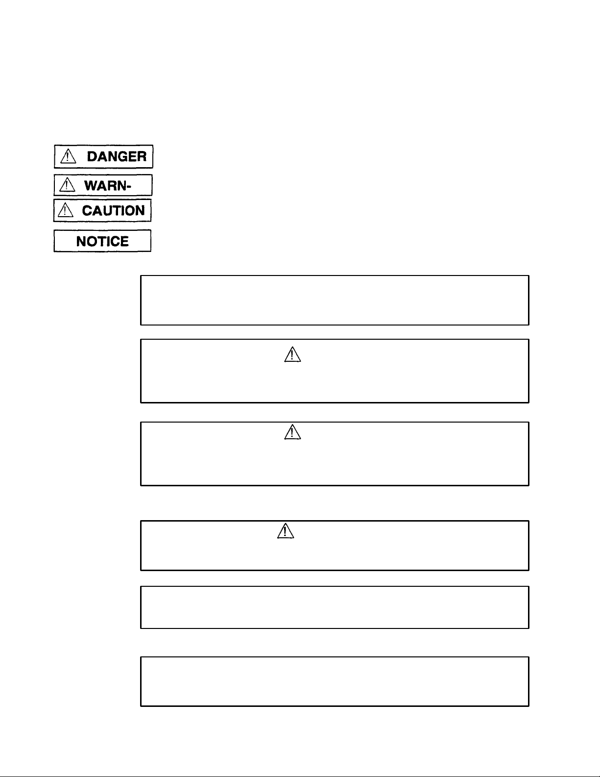
The following symbols, found throughout this manual, alert you to potentially dangerous conditions to the operator, service
personnel, or to the equipment.
This symbol warns of immediate hazards which will result in severe injury or death.
This symbol refers to a potential hazard or unsafe practice which could result in injury or
death.
This symbol refers to a potential hazard or unsafe practice which could result in injury,
product, or property damage.
This symbol refers to information that needs special attention or must be fully understood,
even though not dangerous.
POST IN PROMINENT LOCATION
The emergency telephone number of your gas supplier and instructions to follow if gas
odor is detected.
DANGER
EXPLOSION HAZARD
If a gas odor is detected, shut down equipment at the main shut-off valve.
Immediately call the emergency phone number of your gas supplier.
WARNING
FIRE HAZARD
For your safety, do not store or use gasoline or other flammable vapors and liquids in
the vicinity of this or any other appliance.
WARNING
Asphyxiation can result from improper ventilation. Do not obstruct the flow of
combustion and ventilation air to and from your cooking equipment.
NOTICE
Be sure the Operator's Manual and important papers are given to the proper authority to
retain for future reference.
FOR YOUR SAFETY
Do not store or use gasoline or other flammable liquids in the vicinity of this or any
other appliance.
Page 3
Congratulations! You have purchased one of the finest pieces of heavy-duty commercial cooking equipment on the market.
Cooking Tips....
..............................................................................……….................................................…………………..32
-
34
PREFIX:
SUFFIX:
1100
Old Honeycutt Road
You will find that your new equipment, like all Southbend equipment, has been designed and manufactured to meet the toughest
standards in the industry. Each piece of Southbend equipment is carefully engineered and designs are verified through laboratory
tests and field installations. With proper care and field maintenance, you will experience years of reliable, trouble-free operation.
For best results, read this manual carefully.
RETAIN THIS MANUAL FOR FUTURE REFERENCE.
TABLE OF CONTENTS:
Safety Precautions.........................................................................................................................................……………………2
Specifications..............................................................................................................................................……………………3-4
Installation.................................................................................................................................................……………………5-20
Operation................................................................................................................................................…………………….21-31
Adjustments............................................................................................................................................…………………….35-36
Maintenance...........................................................................................................................................…………………….37-38
Parts/Accessories...................................................................................…………………….................................................39-40
Warranty......................................................……………………………………............................................................................41
LOCATION AND IDENTIFICATION OF NAME PLATE
This manual applies to Model Series GH Convection Ovens. You can determine your oven by inspecting the identification plate
located at the base of the front panel, between the door and the control panel. Letters in the model number are described below.
G-GAS
H - HALF-SIZE
SC - STANDARD CONTROLS
CC - CYCLE CONTROLS
CH - COOK & HOLD
PC - PROGRAMMABLE CONTROLS
RT - RACK TRACK CONTROLS
Read these instructions carefully before attempting installation. "Installation" and" Start Up" should be performed by a qualified
installer. Unless the installation instructions for the above-described Southbend product are followed and performed by a qualified
service technician (a person experienced in and knowledgeable with the installation of commercial gas and/or electric cooking
equipment) then the terms and conditions of the Manufacturer's Limited Warranty will be rendered void and no warranty of any kind
shall apply.
In the event you have questions concerning the installation, use, care, or service of the product, write to the Technical Service
Department, Southbend, 1100 Old Honeycutt Road., Fuquay-Varina, North Carolina 27526.
NOTICE
This product is intended for commercial use only; not for household use.
IMMEDIATELY INSPECT FOR SHIPPING DAMAGE
All containers should be examined for damage before and during unloading. The freight carrier has assumed
responsibility for its safe transit and delivery. If damaged equipment is received, either apparent or concealed,
a claim must be made with the delivering carrier.
A) Apparent damage or loss must be noted on the freight bill at the time of delivery. The freight bill must then
be signed by the carrier representative (Driver). If the bill is not signed, the carrier may refuse the claim.
The carrier can supply the necessary forms.
B) A request for inspection must be made to the carrier within 15 days if there is concealed damage or
loss that is not apparent until after the equipment is uncrated. The carrier should arrange an inspection. Be certain to hold all contents plus all packing material.
A MIDDLEBY COMPANY
PAGE1
Fuquay-Varina. NC 27526
É(919)552-9161
É(800) 348-2558
FAX (919) 625-6143
FAX (919) 552-9798
Page 4
MODELS GH-10
"
UTILITY INFORMATION:
OPTIONAL
- 240/60/1
or 3* phase
(220
to
240
vote)
- supply must be
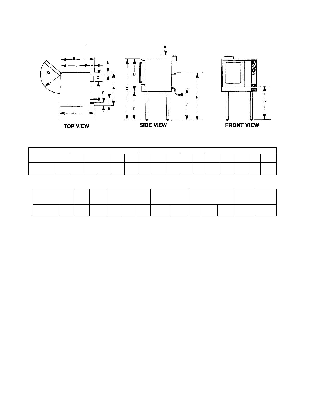
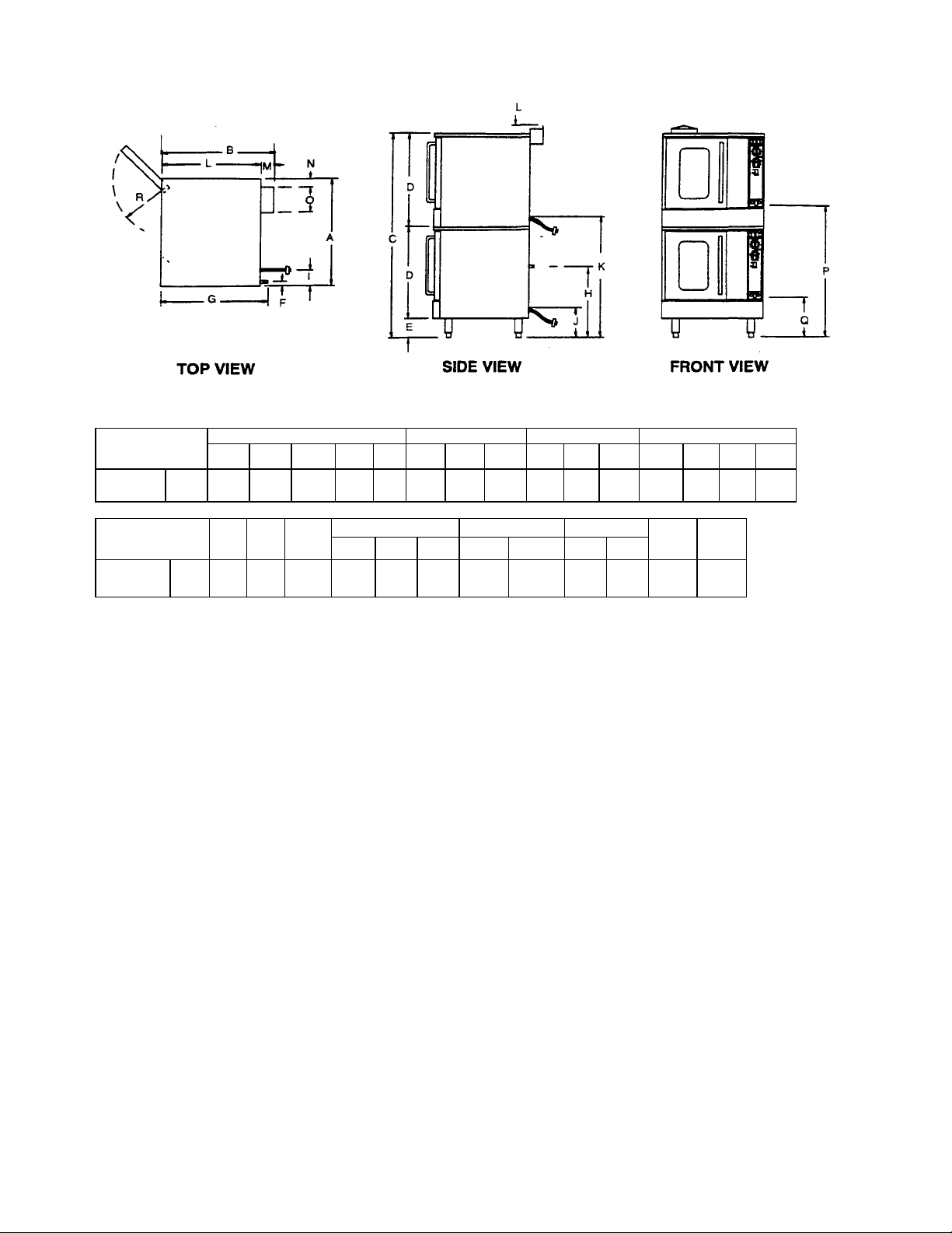
NOTE: Not for Scale. For Dimensional Purposes Only.
DIMENSIONS: ( ) = Millimeters
MODELS
STANDARD
DEPTH
Width
GH-10 30"
(762)
EXTERIOR
Depth Height
29 3/4
55"
(756)
(1397)
¾” GASCONNECTION
D E F G H
29"
26"
2 1/2"
(737)
(660)
(64)
28"
(711)
38"
(965)
ELECTRICAL
J K L M N 0
I
2 1/2"
35"
(64)
(889)
3/4"
(19)
26 3/4
(679)
FLUE
3"
(76)
2"
(64)
Interior Dimensions: 15 3/4 "W x 21 1/4"D x 20H Capacity:Five (5) 13" X 18" pans ( ) = Millimeters
MODELS
STANDARD
DEPTH
Oven
Bottom
GH-10 33"
(838)
Door
Opening
P
16 3/4"
OVEN INTERIOR
Width Depth Height
Q
15 3/4"
(406)
(400)
21 1/4"
(540)
RACKCLEARANCE
Width Depth
20"
281/4"
(508)
(718)
CRATE SIZE
Width Depth Height
21"
(533)
45"
(1143)
39"
(991)
42"
(1067)
Cubic
Volume
42.7 cu. ft.
1.21 cu. m.
5 1/2"
(203)
Crated
Weight
GAS GH-10 - Total 30,000 BTU (High).
20,000 BTU (Low)
One 3/4" male connection
(for location,see drawing above).
Required supply pressure:
Natural Gas 7" W.C.
Propane Gas 11" W.C.
ELECTRIC- (for location, see drawing above).
STANDARD: 120/60/1 - furnished with 6-ft
cords w/3-prong plug. NEMA#5-15p. Total
maximum amps 7.9.
wired to junction box with terminal block located at rear of deck.
Total maximum amps 3.8.
OPTIONAL - 240/50/1 or 3* phase (208 to 240 vote) - supply must be
wired to junction box with terminal block located at rear of deck.
Total maximum amps 6.0.
*All units are shipped single phase. Single phase units can be easily
converted to three phase.
PAGE 2
Page 5
MODELS: GH-20 NOTE: Not for Scale. For Dimensional Purposes Only.
3/4"
GAS
FLUE
92.7cu.ft.
UTILITY INFORMAT
ION:
OPTIONAL
- 240/60/1
or 3* phase
(220
to
240
volts)
- supply must be
DIMENSIONS: ( ) = Millimeters
MODELS
STANDARD
DEPTH
GH-20
Width
13”
(320)
EXTERIOR
Depth
Height D E F G H I J K L M N 0
29 3/4"
(756)
64"
(1627)
29"
(737)
6"
(152)
2 1/2"
(64)
28"
(711)
18"
(457)
ELECTRICAL
2 1/2"
(64)
15"
(381)
44"
(1118)
26 3/4"
(679)
3"
(76)
2"
(51)
51/2"
(140)
MODELS
STANDARD
DEPTH
GH-20
Oven
13"
(330)
Oven Door
42"
16 3/4"
(1067)
(425)
OVEN INTERIOR-Each RACK CLEARANCE
21 1/4"
(572)
Height
Depth Width Depth
20"
(510)
22"
(559)
(1397)
Width Depth
15"
(381)
55"
CRATE SIZE
Height
451/2"
(1156)
64"
(1627)
Cubic
lume
cu. m.
Crated
1040
GAS GH-10 -Total 60,000 BTU (High).
40,000 BTU (Low)
One 3/4" male connection
(for location,see drawing above).
Required supply pressure:
Natural Gas 7" W.C.
Propane Gas 11" W.C.
ELECTRIC- (for location, see drawing above).
STANDARD: 120/60/1 - furnished with 6-ft
cords w/3-prong plug. NEMA#5-15p. Total
maximum amps 7.9.
wired to junction box with terminal block located at rear of deck. Total
maximum amps 3.8.
OPTIONAL - 240/50/1 or 3* phase (208 to 240 volts) - supply must
be wired to junction box with terminal block located at rear of
deck. Total maximum amps 6.0.
*AII units are shipped single phase. Single phase units can be
easily converted to three phase.
PAGE 3
Page 6
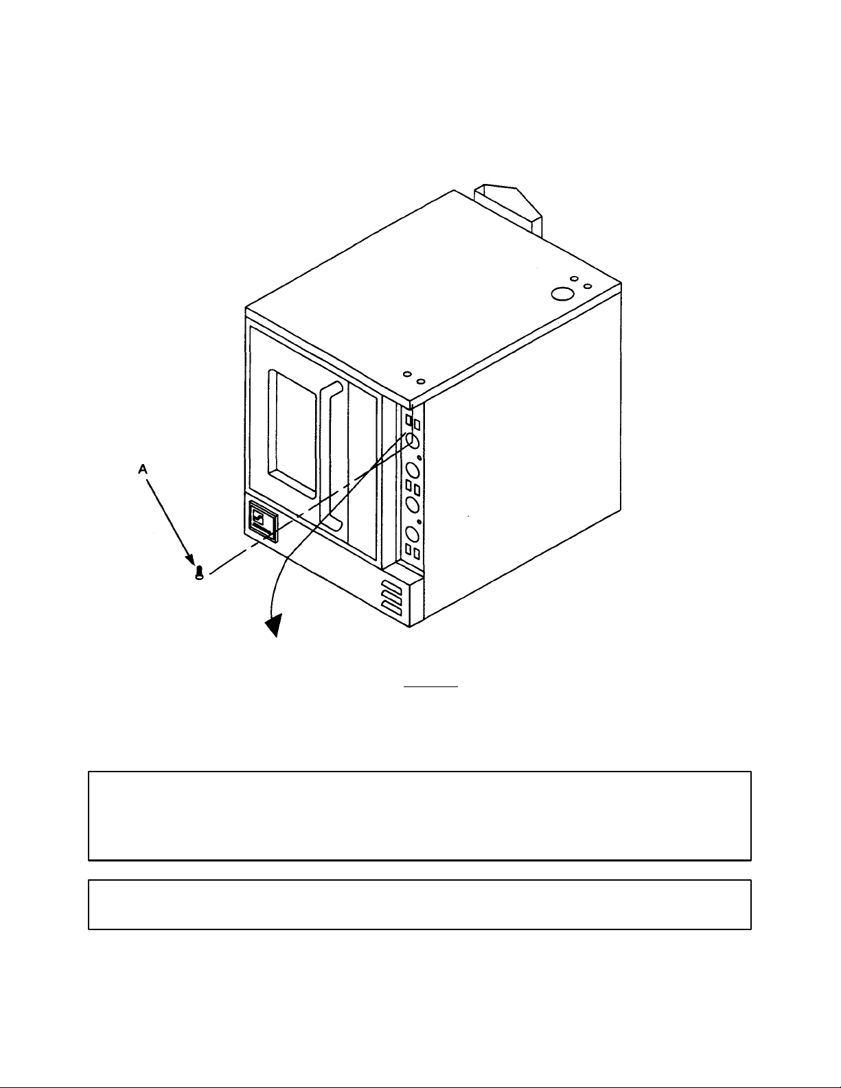
LOCATION OF WIRING DIAGRAM ON UNIT:
Electrical diagram is located on the left side of the control panel. It can be viewed when the panel is pulled down. To
access the diagram remove screw at top of control panel (Item "A") on figure 1. Then pull control panel down by placing
fingers under the lip portion at the top of the control panel and placing your thumb on front of the unit and pulling forward
on the top of the control panel. Follow the arrow on figure 1.
FIGURE 1
NOTICE
Southbend reserves the right to change specifications and product design without notice. Such revisions
do not entitle the buyer to corresponding changes, improvements, additions, or replacements for
previously purchased equipment.
NOTICE
These procedures must be followed by qualified personnel or warranty will be void.
PAGE 4
Page 7

GENERAL:
NOTICE
The unit, when installed, must conform with local codes, or in the absence of local codes, with the
National Fuel Gas Code, ANSI Z223.1-latest edition. Natural Gas Installation Code, CAN/CGAB149.1, or the Propane Installation Code, CAN/CGA-B149.2, as applicable.
The unit, when installed, must be electrically grounded and comply with local codes, or in the
absences of local codes, with the National Electrical Code ANSI/NFPA 70-latest edition, or the
Canadian Electrical Code, CSA c22.2, as applicable.
Canadian installation must comply with CAN/CGA-B149.1 natural gas installation code, code
CAN/CGA- B149.2 propane installation code, and CSA C22.1 Canadian electrical code, parts I or
local codes.
GAS CONNECTION:
The Serial Plate is located behind the combustion cover panel, below the oven door. It is on the right side, attached to
the base of the oven. It indicates the type of gas the unit is equipped to bum.
All Southbend equipment is adjusted at the factory. Check type of gas on serial plate.
These models are design-certified for operation on natural or propane gases.
This appliance should be connected ONLY to the type of gas for which it is equipped.
A 3/4" NPT line is provided at the rear for the connection. Each unit is equipped with an internal pressure regulator which
is set for 4.5" W.C on high fan, 2.5" W.C manifold pressure on low fan for natural gas or 10.5" W.C manifold pressure on
high fan, 7" W.C manifold pressure low fan for propane gas. Use 1/8" pipe tap on the top of the burner manifold for
checking pressure.
An optional gas connection is available through the bottom of the oven base. If the incoming gas line needs to connect
through the bottom of the oven, refer to page 7 for optional gas connection
If applicable, the vent line from the gas appliance pressure regulator shall be installed to the outdoors in accordance with
local codes or, in the absence of local codes, with the National Fuel Gas Code, ANSI Z223.1 Latest Edition. Canadian
installation must comply with CAN/CGA-B149.1 Natural Gas Installation Code, Code CAN/CGA-B149.2 Propane
Installation Code.
An adequate gas supply is imperative. Undersized or low pressure lines will restrict the volume of gas required for satisfactory performance. Fluctuations of more than 25% on natural gas or 10% on propane gas will create problems and
affect burner operating characteristics. A 1/8" pressure tap is located on the top of the manifold to measure the manifold
pressure.
An adequate gas supply line to the unit should be no smaller than the l.D. of the pipe from the unit to which it is connected.
Purge the supply line to clean out any dust, dirt, or other foreign matter before connecting the line to the unit. Each unit
has a manual shut off valve in the control compartment and a safety shut off valve behind the manifold cover. Use pipe
joint compound which is suitable for use with LP gas on all threaded connections. Test pipe connections thoroughly for
gas leaks. USE SOAPY WATER ONLY FOR TESTING ON ALL GASES. NEVER USE AN OPEN FLAME TO CHECK
FOR GAS LEAKS. ALL CONNECTIONS MUST BE CHECKED FOR LEAKS AFTER THE UNIT HAS BEEN PUT IN
OPERATION. Test pressure should not exceed 1/4" W.C.
PAGE 5
Page 8
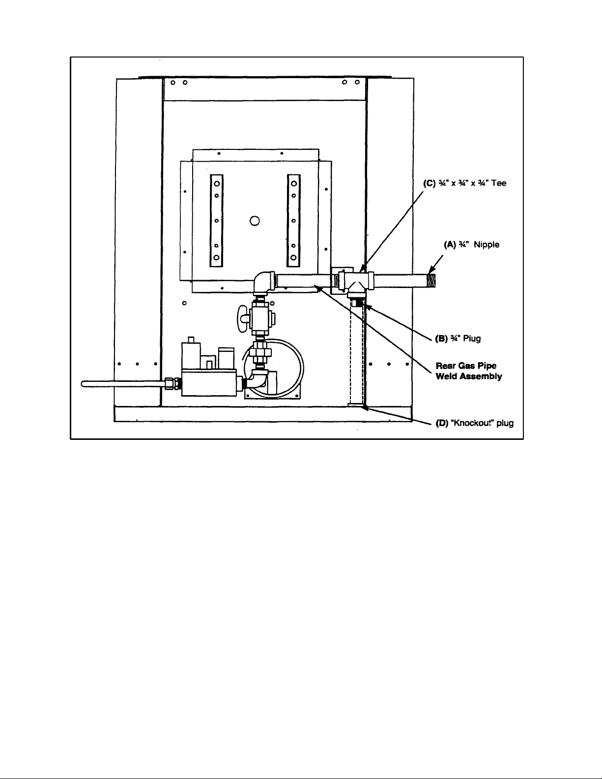
FIGURE 2
OPTIONAL GAS CONNECTION:
To install gas supply using the optional gas connection, follow the steps below:
1. Open the door and remove the three (3) screws in the top of the combustion cover. Remove cover from
oven.
2. Remove one (1) screw in front cover of right body side, and five (5) screws along rear.
3. Remove 3/4" nipple (Item A) and remove 3/4" plug (Item B) from 3/4" x 3/4" x 3/4" manifold tee (Item C).
4. Install 3/4" plug (Item B) into rear of tee where the 3/4" nipple (Item A) was, originally.
5. Remove "knockout" plug (Item D) from base of oven.
6. Install a new 3/4" NPT nipple of sufficient length to extend out of the bottom of the oven and reach the gas
supply connection.
7. Reinstall the body side, and front combustion cover.
PAGE 6
Page 9
WARNING
This appliance and its individual shut-off valve must be disconnected from the gas supply piping system
during any pressure testing of the system at test pressures in excess of 1/2 PSIG (3.45 KPa).
This appliance must be isolated from the gas supply piping system by closing its individual manual
shutoff valve during any pressure testing of the gas supply piping system at test pressure equal to or
less than 1/2 PSIG 93.45 KPa.
If this equipment is being installed at over 2,000 feet altitude and was not specified on order, contact the appropriate authorized
Southbend Service Representative or the Southbend Service Department. Failure to install with proper orifice sizing will result in
improper performance and may void the warranty.
ELECTRICAL CONNECTIONS:
I .115 VAC - 60 Hz - SINGLE PHASE
A. Ovens with this electrical rating are factory equipped with a three-wire cord and three-prong plug which fits
anystandard 115V three-prong grounded receptacle. A separate 15 amp supply is needed for each oven.
B. CANADIAN INSTALLATIONS ONLY:
On G Series, single ovens, a cord set is NOT furnished. The supply must be brought through the service panel in
the rear of the unit and connected to the terminal block provided. The unit must be adequately grounded.
On G Series, double oven units, the supply for both ovens is combined. One supply for both units must be
brought through the service panel and connected to the terminal block provided. An adequate supply must be
provided.
Use 75°C wire for all supply lines.
II.208/236 VAC - 60 Hz - SINGLE PHASE & THREE PHASE
Ovens with this electrical rating are factory equipped with a two (2) pole terminal block. To connect supply wires
remove cover from connection box at left rear of oven. Route supply wires and ground wire through hole with strain
relief fitting above the connection box. Insert supply wires, one each, into the two poles of the terminal block and
tighten screws in terminal block. Insert ground wire into ground lug and tighten screw. Replace cover. Three-phase
ovens are wired as above, using only two supply wires. The third supply wire is not connected and must be properly
terminated.
III.220 VAC-50 Hz-SINGLE PHASE
Oven equipped with this voltage rating should be wired exactly as in II. above.
WARNING
This appliance is equipped with a three-prong (grounding) plug for your protection against shock hazard
and should be plugged directly into a properly grounded three-prong receptacle. Do not cut or remove the
grounding prong from this plug. (115V units only.)
NOTICE
If applicable, the vent line from the gas appliance pressure regulator should be installed to the outdoors in
accordance with local codes or, in the absence of local codes, with the National Fuel Gas Code, ANSI
Z223. 1-latest edition, Natural Gas Installation Code, CAN/CGA-B149.1, or the Propane Installation Code,
CAN/CGA-B149.2, as applicable.
PAGE 7
Page 10

CLEARANCES:
Minimum Clearances - Inches (mm)
Back
Right Side
Left Side
Floor
From Combustible
Construction
0.0
0.0
2.0
0.0
All units must be installed in such a manner that the flow of combustion and ventilation air are not obstructed. Provisions
for an adequate air supply must be provided. Do not obstruct the front or rear of the unit, as combustion air enters through
this area. Be sure to inspect and clean the ventilation system according to the ventilation equipment manufacturer's
instructions.
Adequate clearance must be provided in aisle and at the side and rear to allow the doors to open sufficiently to permit the
removal of the racks and for serviceability.
No additional clearance from the sides and back is required for service as the units are serviceable from the front.
Do not locate unit adjacent to any high heat or grease producing piece of equipment, such as a range top, griddle,
fryer, etc., that could allow radiant heat to raise the exterior temperature of the oven above 130°F (54°C).
From Non-Combustible
Construction
0.0
0.0
0.0
0.0
DO NOT MOUNT ABOVE OTHER COOKING EQUIPMENT.
NOTICE
Local codes regarding installation vary greatly from one area to another. The National Fire Protection
Association, Inc. states in its NFPA 96 latest edition that local codes are the "authority having jurisdiction"
when it comes to installation requirements for equipment. Therefore, installations should comply with all
local codes.
EXHAUST FANS AND CANOPIES: Canopies are set over ranges, ovens, etc., for ventilation purposes. It is
recommended that a canopy extend 6" past the appliance and the bottom edge be located 6'6" from the floor. Filters
should be installed at an angle of 45 degrees or more from horizontal. This position prevents dripping grease and facilitates collecting the run-off grease in a drip pan, usually installed with a fitter. A strong exhaust fan tends to create a
vacuum in the room and may interfere with burner performance or may extinguish pilot flames. Fresh air openings
approximately equal to the fan area will relieve such a vacuum.
WALL EXHAUST FAN: The exhaust fan should be installed at least 2" above the vent opening at the top of the unit.
DIRECT CONNECTION: If the unit is connected directly to an outside flue, an AGA/CGA design certified, down draft
diverter must be installed at the flue outlet of the oven and connected to the flue. Part # for the diverter is 117571 and can
be purchased from parts distributor.
In case of unsatisfactory performance on any appliance, check the appliance with the exhaust fan in the "OFF" position.
Do this only long enough to check equipment performance. Then turn hood back on and let it run to remove any exhaust
that may have accumulated during the test.
PAGE 8
Page 11
NOTICE
Proper ventilation is the owner's responsibility. Any problem due to improper ventilation will not be
covered by warranty.
WARNING
Improper ventilation can result in personal injury or death. Ventilation which fails to property remove
flue products can cause headaches, drowsiness, nausea, or could result in death.
LEVELING:
Unit must be level to assure maximum performance. Improper leveling may void warranty.
TO INSTALL:
1. Remove crating with care. Remove all wood blocking, packing material and accessories.
2. The legs should be installed after the unit has been uncrated, near the area where it will be used.
3. Raise unit sufficiently to allow legs to be installed with four bolts.
4. The legs can be adjusted to overcome an uneven floor. Use a spirit level in all directions on the middle oven rack.
5. When casters are supplied, the locking swivel type casters should be installed in the front.
6. Casters are provided with a zerk fitting for lubrication.
When a lift truck or other mechanical means are not available, and manual labor is involved, please consider the
following suggestions.
1. Raise each comer or, if feasible, raise an entire side by "leaning" the unit.
2. For safety, "shore up" and support the raised section with an adequate blocking arrangement strong enough to
support the load.
3. When long legs are being installed and the unit must be tipped beyond the stable point, lean unit against a strong
wall or other suitable structure to prevent it from "falling over."
4. When absolutely necessary and unit must be placed "completely over," lay ONLY on its LEFT side. Take care to
protect finish on left side.
5. Bring unit to its straight position gently. NEVER DROP, or allow unit to FALL.
NOTE: An "open" storage rack arrangement may be incorporated on units supported by high legs. Directions and
illustrations are provided on another sheet and are also provided with these parts. Refer to diagram titled
Assembly for open rack storage in the installation section of this manual.
Adequate restraining means must be attached to rear of appliance when installed. Installation must conform
to local codes as applicable.
WARNING
For an appliance equipped with casters, instructions shall be that installation shall be made with a connector that complies with the Standard for Connectors for Moveable Gas Appliances, ANSI Z21.69 or
Connectors for Movable Gas Appliances, CAN/CGA-6.16-M87, and a quick-disconnect device that
complies with the Standard for Quick-Disconnect Devices for Use With Gas Fuel, ANSI Z21.41 or QuickDisconnect Devices for Use with Gas Fuel, CAN1-6.9, adequate means must be provided to limit the
movement of the appliance without depending on the connector and the quick-disconnect device or its
associated piping to limit the appliance movement.
WARNING
If disconnection of this restraint is necessary to move the appliance for cleaning, etc., reconnect it
when the appliance is moved to it originally installed position.
PAGE 9
Page 12
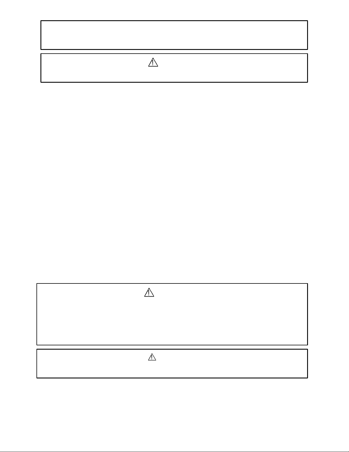
LEGS FOR SINGLE DECK OVENS
FIGURE
4
ITEM PART NUMBER DESCRIPTION
* 1146213 3/8 x 16x 1 Hex Head Bolt
* 1146513 3/8 Lock Washer
* 1146522 3/8 Flat Washer
A 1175090 Single Deck Adj. Leg
B 1174266 Adj. Foot for Leg
FIGURE 3
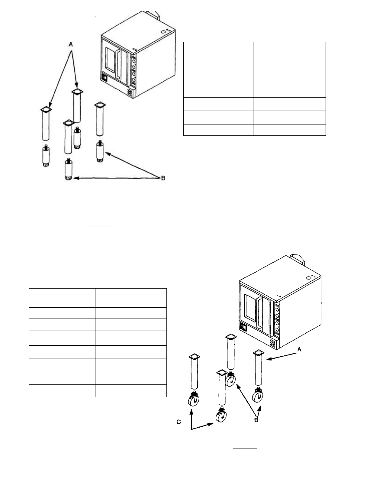
CASTERS FOR SINGLE DECK OVENS
ITEM PART NUMBER DESCRIPTION
?
1173584 Flanged Foot for Leg
* Not shown (qty. 16 used per unit to attach legs to unit.)
† Flanged Foot is optional replacement for 1174266
* 1146213 3/8 x 16 x 1 Hex Head Bolt
• 1146513 3/8 Lock Washer
* 1146522 3/8 Flat Washer
A 1175089 Single Deck Caster Leg
B 1174263 Caster less Brake
C 1174264 Caster with Brake
+ 1174265 Caster Package
* Not shown (qty. 16 used per unit to attach legs to unit.)
† This package contains 4 casters, 2 with locks, 2 with
out locks no legs pads, bolts or washers are included
with this package.
Page 13
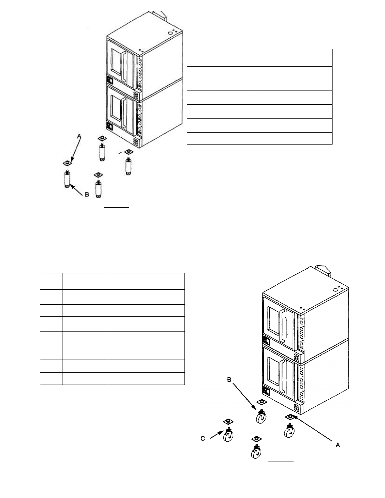
LEGS FOR DOUBLE STACKED OVENS
ITEM PART NUMBER
DESCRIPTION
FIGURE 5
NOTE: Leg Pads (Item A) are installed on oven at
factory when units are ordered stacked.
* 1146213 3/8 x 16 x 1 Hex Head Bolt
* 1146513 3/8 Lock Washer
* 1146522 3/8 Flat Washer
A 1172788 Leg Pad
B 1174259 SS Leg, 3/4 Stud
†
1174260 Leg Package
* Bolts, lock washers, and flat washers not shown.
Requires 4 of each per pad for a total of 16 each per
double oven.
†This package consists of 4 legs only. No leg pads,
bolts or washers are included in this package.
CASTERS FOR DOUBLE STACKED OVENS
ITEM PART NUMBER DESCRIPTION
* 1146213 3/8 x 16 x 1 Hex Head Bolt
* 1146513 3/8 Lock Washer
* 1146522 3/8 Flat Washer
A 1172788 Leg Pad
B 1174263 Caster less Brake
C 1174264 Caster with Brake
†
1174265 Caster Package
* Bolts, lock washers, and flat washers not shown.
Requires 4 of each per pad for a total of 16 each per
double oven.
†This package consists of 4 legs only. No leg pads,
bolts or washers are included in this package.
PAGE 11
FIGURE 6
Page 14

WARNING
For an appliance equipped with casters, the installation shall be made with a connector that
complies with the Standard for Connectors for Movable Gas Appliances, ANSI Z21.69, or
Connectors for Movable Gas Appliances, CAN/CGA-6.16-M87, and a quick-disconnect device that
complies with the the Standard for Quick-Disconnect Devices for Use with Gas Fuel, ANSI Z21.41
or Quick-Disconnect Devices for Use with Gas Fuel CAN 1-6.9.
Adequate means must be provided to limit the movement of the appliance without depending on
the connector and the quick-disconnect device or its associated piping to limit the appliance
movement.
WARNING
To avoid accidental gas disconnection and potential explosion:
If disconnection of this restraint is necessary to move the appliance for cleaning, etc., reconnect it
when the appliance is moved to its originally installed position.
Adequate restraining means must be attached to rear of appliance when installed. Installation must conform to local
codes as applicable.
For units not equipped with flame safety devices, be sure all valves are turned off prior to disconnecting. When
reconnecting, be sure all valves are turned off and all pilots are lit.
PERFORMANCE CHECK:
The following items should be checked within the first 30 days of operation by a qualified service technician.
1. Verify equipment is level.
2. Verify proper electrical characteristics - voltage, cycle, phase.
3. Check thermostat operation; calibrate if required.
4. Check ventilation.
5. Check electrical connections - external and internal.
6. Check door for proper alignment, tension, seal, and adjustment.
7. Check timers, switches and motor for proper installation and operation.
8. Check for any damage to unit from shipping or installation.
9. Check for proper clearance from combustible materials.
10. Verify proper type of gas
11. Verify gas supply and pressure (pressure regulator is already installed at factory.)
12. Check gas connection and check for leaks.
It is common for new products to require a burn-off time to dry out insulation and metal cooking surfaces.
PAGE 12
Page 15

INSTRUCTIONS FOR STACKING UNITS IN THE FIELD
1.
After uncrating units, identify the unit that is to
3.
Next, locate and remov
e screws that hold
be the bottom unit. If the units were shipped
unstacked, to be stacked at installation, then the
unit intended as the bottom unit will have a set
of leg pads bolted to the bottom of the oven.
FIGURE 7
2. The bottom unit will have a box of four (4) legs (P/N 1174260) or casters (P/N 1174265) depending on what was
ordered with the oven. Remove and attach legs or casters to the bottom of the lower unit. The pads that the legs
or casters thread into are already bolted to the bottom of this oven.
NOTICE
If installing casters, place the two (2) casters that have locks, on the front of the unit so it may be
locked into position easily.
the combustion chamber cover on the top
and bottom ovens. Refer to figure 8,
screws (Items "A" and "B"). The screw
(labeled Item "B") is located behind the
access panel on the lower right body side.
Remove screw (item B) and screws (item
C) from rear of oven. Remove body side to
acess compartment
4. Remove "knockout" hole (Item D) in top of
bottom oven to allow for gas interpiping.
PAGE 13
Page 16

5.
Next, lift the top unit and position it on top of the
lower unit as shown in Figure 9.
6. Repeat Step 3 for top oven.
7. Move to the rear of the ovens and remove screws (Items "A" and "B") in Figure 10.
8. Place tie bracket (P/N 1175058) on rear of unit. Line up holes in the tie bracket with holes in rear of unit.
(Refer to figure 11)
9. Reinsert the six screws taken out in step 7 (Items "A" and "B").
PAGE 14
Page 17

9. Connect the top and bottom gas connections as shown. Remove
the plug from the tee in the top oven, and reinstall as shown in
Figure 12 (Item A).
10. Remove the plug in the bottom 3/4" x 3/4" x 3/4" tee and discard.
11. Rotate the tee in the bottom oven 180°, so that the hole that was
plugged is now turned up.
12 Connect the items B, C and D as shown in Figure 12.
13. Test all connections for leaks.
14. The gas for both ovens can now be connected (Item E) as shown in
Figure 12.
15. Insert 4 bolts, flat washers, and lock washers through the top of the
bottom oven and into the leg pad bolt holes for the top oven.
(Item F)
FIGURE 12
16. Install flue stack as shown in figure 13.
Insert the top of the flue stack into the
bottom of the top flue. Push up and let the
flue stack fall over the bottom flue.
17. In front of units, replace the right body side
and combustion covers for the top unit that
were removed in step 3.
18. The unit is ready for the utility connection to
be made.
ITEM PART NUMBER DESCRIPTION
A 1177640 Flue Box
B 1175085 Tie Bracket
FIGURE 13
PAGE 15
Page 18

PARTS LIST FOR OPEN RACK STORAGE GUIDE
Includes Solid Shelf (Optional)
ITEM PART NUMBER DESCRIPTION 1175506
* 1146304 10x 1/2 Phillips Screw 18
A 1177296 Frame Hanger 2
B 1175514 Stop Channel 1
C 1175438 Side Rack 11 Position 2
D 1175294 Shelf Shallow 1
11 Position
Shallow w/Shelf
E 11------- Front Channel Frame
F 11------- Rear Channel Frame
G 6660 Side Rack Clip 4
PAGE 16
Page 19

ASSEMBLY INSTRUCTIONS FOR OPEN RACK STORAGE
Includes Solid Shelf (Optional)
1. Refer to the parts chart on the first page, and verify that all parts and quantities are correct.
2. Attach frame hanger (1177296) (Item "A") to underside of oven. Be sure the flanged side of the rack hanger faces
the front of the unit. Refer to figure 14.
NOTE: All holes are pre-punched, and assembly should be done with the screws provided.
3. Attach frame hanger (1177296) (Item "A"), to underside of oven. The rear frame hanger should be mounted so that
the flanged side of the rack hanger faces the rear of the unit. Refer to figure 14.
4. Hang rack guides from outside frame hanger holes for racks, or inside hanger holes for pans. Refer to figure 15.
Side View Bottom View
FIGURE 15
PAGE 17
Page 20

5. Insert bottom of rack guides into front and rear holes in shelf. If you have an open rack guide kit, insert bottom of rack
guides in to holes in the left and right side of front and rear channel frames. Refer to figure 16.
FIGURE 16
6. Secure bottom of rack guide to shelf or front and rear channel frames with side rack clips. Refer to figure 17.
FIGURE 17
PAGE 18
Page 21

7. Install rack stop to rear frame hanger and rear of bottom shelf, or rear channel frame. Refer to figure 18.
FIGURE 18
PAGE 19
Page 22

THEORY OF OPERATION
CONTROL FUNCTIONS:
FIGURE
19
STANDARD CONTROL PANEL
FOR STANDARD CONTROL UNITS - SC MODELS
A. The "ON-OFF" switch (top left) controls all power in the unit. In the
"ON" position, power is made available to the lights, thermostat and
motor circuitry.
B. The "COOK-COOL" switch (top right) controls the fan relative to door
position.
1. In the "COOK" position, the fan and heat source are "ON" when the
doors are closed. Opening the doors shuts off the fan and heat
source.
2. In the "COOL" position, the fan is on regardless of whether doors are
open or closed (power switch "ON"). Opening doors shuts off heat
source - fan remains on.
3. General - Fan is always on when unit is "ON", unless in cook position and doors are open. Fan does.not cycle with heat source.
"COOL" position is useful for rapid cool down of oven after cooking
is completed (doors open).
C. The "COOK TEMPERATURE" control regulates the oven tempera-
ture.
Setting the control to a position greater than the oven temperature
energizes the heating source and illuminates the "HEAT ON" light.
NOTE: Once the set temperature is achieved, the heat source and light will go
off, and then cycle as required to maintain set temperature.
D. The "HEAT ON* indicator light cycles with the burners and is illuminated
when the burners are on.
E. The 1 Hour timer is mechanical and is only a time reminder. It has no
control over oven.
F. Fan "HI-LO" switch allows selection of fan speed at user's
preference. G. HIGH/LOW BTU switch controls the BTUs being
supplied to the
burners. On HIGH fan, 30,000 BTUs; on LOW fan 20,000 BTUs
A On-Off Switch (Power)
B Cook-Cool Switch (Fan)
C Temperature Control
D Heat On Indicator Light
E 1 Hour Timer
F High Low Fan Switch
G High Low BTU Switch
H Fuse ( only on 208 or higher voltages)
CONTROL OPERATION:
A. Preheat - Oven preheats to "COOK" temperature setting.
1. Turn power to "ON".
2. Set cook temperature to desired temperature. When oven temperature is equal to the cook temperature control setting, the
"HEAT-ON" light will go out. The oven is now preheated and product
may be placed in oven.
3. Choose HIGH or LOW fan speed.
4. Choose HIGH or LOW BTUs
B. Cook
1. Preheat as above.
2. Load oven. The "HEAT-ON" light will cycle on and off with the heat
source.
3. Use of timer as a REMINDER is optional. Timer does not control
cook length.
C. Rapid Cool Down
1. Temperature control at full counterclockwise.
2. COOK-COOL Switch - "COOL"
3. Doors open.
PAGE 20
Page 23

FOR CYCLE CONTROL UNITS - CC MODELS
CYCLE CONTROL
CONTROL FUNCTIONS:
FIGURE
20
B "Cook
-
Cool" Switch (Fan)
D Heat In Indicator Light
G "On
-
Off" Switch (Pulse Timer)
CONTROL PANEL
A "On-Off" Switch (Power)
C Cook Timer
E Cook Thermostat
F "High-Low" Switch (Fan Speed)
A. The "ON-OFF" switch (top left) controls all power in the unit. In the
"ON" position, power is made available to the lights, thermostat and
motor circuitry.
B. The "COOK-COOL" switch (top right) controls the fan relative to door
position.
1. In the "COOK" position the fan and heat source are "ON" when the
doors are closed. Opening the doors shuts off the fan and heat
source.
2. In the "COOL" position, the fan is on regardless of whether doors are
open or closed (power switch "ON"). Opening doors shuts off heat
source - fan remains on.
3. General - Fan is always on when unit is "ON", unless in "COOK"
position and doors are open. Fan does not cycle with heat source.
"COOL" position is useful for rapid cool down of oven after
cooking is completed (doors open).
C. The timer is mechanical, and is only a Time" reminder. It has no
control over the oven.
NOTE:Once the set temperature is achieved, the heat source and light
will go off, and then cycle as required to maintain set temperature.
D. The "HEAT ON" light indicates burners are in operation.
E. The "COOK TEMPERATURE" control regulates the oven tempera
ture. Setting the control to position greater than the oven temperature
energizes the heating source and illuminates the "HEAT ON" light.
F. The "CYCLE TIMER" selects the cycle mode in the "ON" position and
bypasses it in the "OFF" position.
G. Fan "HI-LOW" switch allows selection of fan speed at user's
preference.
H. The "FAN DELAY TIMER". During the time period set on the timer,
the blower cycles off and on in 20-70 second intervals set by the
operator. 'When the timer times out the blower runs continuously in a
normal cook mode.
I. The "CYCLE TIMER" selects the cycling time of the blower, from 20
to 70 seconds.
J. The "HI-LOW" BTU switch controls the number of BTUs being
supplied to the burners (30,000 BTUs high, 20,000 BTUs low).
CONTROL OPERATION:
The procedure for cooking only in a Cycle Control unit is the same as that
of a Standard Control unit.
A. Cycle
1. Switch power on.
2. Set COOK TEMPERATURE to desired temperature.
3. The HEAT ON light will be off once the oven preheats to the set
cook temperature.
4. Load oven with the product.
5. Switch CYCLE TIMER to ON.
6. Set FAN DELAY TIMER to desired time.
7. Set CYCLE TIMER to desired cycling.
8. Once the FAN DELAY TIMER times out the oven will operate in a
normal cook mode with the blower running continuously.
9. Use of COOK TIMER as a REMINDER is optional. COOK TIMER
does not control cook length.
10. Remove product after it is cooked.
B. Rapid Cool Down
1. TEMPERATURE CONTROL at full counterclockwise.
2. Cook-Cool Switch "COOL".
3. Doors open.
H Fan Delay Timer
I Pulse Timer
J Hi-Low BTU Switch
K Fuse ( only on 208 or higher voltages)
PAGE 21
Page 24

FOR COOK AND HOLD CONTROL UNITS (ANALOG CONTROLS) - CH MODELS
CONTROL FUNCTIONS:
A "On
-
Off" Switch (Power)
C Cook Timer
H Hold Thermostat
J Cook Hold Timer
COOK AND HOLD CONTROL PANEL
A. The "ON-OFF switch (top left) controls all power in the unit. In the
"ON" position, power is made available to the lights, thermostat and
motor circuitry.
B. The "COOK-COOL" switch (top right) controls the fan relative to door
position.
1. In the "COOK" position the fan and heat source are "ON" when the
doors are closed. Opening the doors shuts off the fan and heat source.
2. In the "COOL" position, the fan is on regardless of whether doors are
open or closed (power switch "ON"). Opening doors shuts off heat
source - fan remains on.
3. General - Fan is always on when unit is "On", unless in "COOK"
position and doors are open. Fan does not cycle with heat source.
"COOL" position is useful for rapid cool down of oven after cooking is
completed (doors open).
C. The timer is mechanical and is only a Time" reminder. It has no control
over the oven:
NOTE: Once the set temperature is achieved, the heat source and light will go
off, and then cycle as required to maintain set temperature.
D. The "HEAT ON" light indicates burners are in operation.
E. The "COOK TEMPERATURE" control regulates the oven tempera
ture. Setting the control to position greater than the oven temperature
energizes the heating source and illuminates the "HEAT ON"
light.
FIGURE 21
B "Cook-Cool" Switch (Fan)
D Heat On Indicator Light
E Cook Thermostat
F Cook Only Cook Hold Switch
G "High-Low" Switch (Fan Speed)
I Hold Indicator Light
K High Low BTU switch
L Fuse (only on 208 or higher voltages)
F. The "COOK ONLY- COOK HOLD" switch, (middle right) selects the
mode of operation
G. Fan "HI-LOW" switch allows the selection of fan speed at user's
preference.
H. The "HOLD TEMPERATURE" control regulates the oven temperature
when the oven is in hold mode.
I. The "HOLD ON" light indicates burners are in operation.
J. The "COOK & HOLD TIMER" controls the cooking time from 0 up to
12 hours. Once the timer times out, the cooking mode switches from
the cook thermostat to the hold thermostat. K. "HI-LOW BTU switch
controls the number of BTUs being supplied to
the burner (30,000 BTUs high, 20,000 BTUs low).
CONTROL OPERATION:
The procedure for cooking only in a Cycle Control unit is the same as that
in a Standard Control unit with the additional procedure of selecting COOK
ONLY mode with the COOK-ONLY_COOK-HOLD switch.
A. Cycle
1. Switch power on.
2. Set COOK TEMPERATURE to desired temperature.
3. The HEAT ON light will be off once the oven preheats to the set cook
temperature.
4. Load oven with the product.
5. Switch CYCLE TIMER to ON.
6. Set FAN DELAY TIMER to desired time.
7. Set cycle timer to desired cycling.
8. Once the PAN DELAY TIMER times out the oven will operate in a
normal cook mode with the blower running continuously.
9. Use of COOK TIMER as a REMINDER is optional. COOK TIMER
does not control cook length.
10. Remove product after it is cooked.
B. Rapid Cool Down
1. Temperature control at full counterclockwise.
2. Cook-Cool Switch "COOL".
3. Doors open.
PAGE 22
Page 25

FOR PROGRAMMABLE CONTROL UNITS - PC MODELS
E
L
M
PROGRAMMABLE CONTROL PANEL CONTROL FUNCTIONS:
The operation of the "ON-OFF" switch is the same as described in the Standard
Controls section.
The following functions are unique to the Cook & Hold programmable control:
The purpose of each button or knob is as follows:
A. Temperature Adjustment Knob - used to set the desired cook or
hold temperature.
B. Time Adjustment Knob - Used to set the cook time.
C. Actual Temperature Button - Used to read the oven interior temperature.
D. Start Timer Button - Used to begin a timed cook sequence.
E. Hi/Lo Fan Speed Button - Used to select High or Low fan speed.
F. Hold Button -Used in Cook and Hold to select hold mode.
G. Continuous/Cycling Fan Button - Used to select fan, continuous or
cycling with heat source.
H. Program Selector Button Used to select programs.
I. Cancel Button - Used to cancel cooking sequence.
J. Program Mode On/Off Button - Used to enter and exit programming
mode.
K. Event Selector Button - Used to step through program.
L. Temperature Display - Indicates temperature set point.
M. Time Display - Indicates cook time left in cook mode or how long
product has been held in hold mode
N. Fan Speed Indicator- Indicates High or Low Pan Speed.
0. Fan Mode Indicator - Indicates Continuous or Cycling Fan.
P. Hold Mode Indicator - Indicates when in hold mode. Flashes when
hold mode will follow cook mode.
Q. Program Indicator - Indicates which program is being used.
A Temperature Adjustment Knob
B Time Adjustment Knob
C Actual Temperature Button
D Start Timer Button
Hi/Lo Fan Speed Button
F Hold Mode Selector Button
G Continuous/Cycling Fan Button
H Program Selector Buttons
1 Cancel Button
J Program Mode on/Off Button
K Event Selector Button
Temperature Display
Time Display
N Fan Speed Indicator
0 Fan Mode Indicator
P Hold Mode Indicator
Q Program Indicator
R High Low BTU Switch (Not shown. Located
at bottom of control panel.
R. High- low BTU Switch allows operator to choose between 30,000
BTUs on high and 20,000 BTUs on low. (Not shown in Figure 22)
PAGE 23
Page 26

TO OPERATE THE CONVECTION OVEN - PC MODELS FOLLOW THESE
The above display shows an untimed bake at
350°
hi
-
The above display shows a timed bake of
30
minutes at
350°
hi-fan
F
I| Cancel Butt
on
M Time Display
0 Fan Mode Indicator
PROGRAMMABLE CONTROL PANEL
STEP-BY-STEP INSTRUCTIONS
PRE-HEAT/UNTIMED COOK:
1. Push power switch "on".
2. Adjust temperature knob until the temperature display indicates desired
temperature.
3. Select fan speed. Shown in fan speed indicator (Item "N"), by pushing
Hi/Lo fan speed button.
4. Select fan mode, shown by fan mode indicator (Item "0"), By
pushing Continuous/Cycling fan button.
The oven will operate as set up even if the cancel button is pushed.
The temperature display will flash until the oven interior temperature
reaches the set point temperature. This tells you the oven is ready to
cook.
A Temperature Adjustment Knob
B Time Adjustment Knob
C Actual Temperature Button
D Start Timer Button
E Hi/Lo Fan Speed Button
Hold Mode Selector Button
G Continuous/Cycling Fan Button
H Program Selector Buttons
J Program Mode On/Off Button
K Event Selector Button
L Temperature Display
speed continuous fan.
TIMED COOK:
1. Follow steps 1 through 4 under pre-heat/ Untimed cook.
2. Adjust time adjustment knob, (Item "B"), until the time display (Item
"M"), shows the desired cooking time.
3. Choose Hi or Low BTUs (Item R)
4. Load the oven and push the start timer button, (Item "D").
The timer will stop when the oven doors are opened, and resume when they
are closed. At the end of timed cook, the control will beep until the cancel
button, (Item "C") is pushed.
N Fan Speed Indicator
P Hold Mode Indicator
Q Program Indicator
R High Low BTU Switch (Not shown. Located
at bottom of control panel)
that cycles with the heat source.
PAGE 24
Page 27

PC MODELS
PROGRAMMABLE
CONTROL PANEL
COOK
&
HOLD
The above display is what you will see during the hold mode
B
C
D
E
Hi/Lo Fan Speed Button
H
I
J
K
L
M
N
Q
1. Follow steps 1, 2 and 3 of timed cook.
2. Push the hold button, (Item "P), to enter hold mode.
3. Adjust temperature knob, (Item "A"), until temperature display, (Item
"L"), indicates desired hold temperature.
4. Select CONTINUOUS on cycling fan mode as you did for cook. Check
fan mode indicator, (Item "N"). Fan speed is always low speed in hold
mode.
5. Load the oven and press the start timer button, (Item "D").
During the cook cycle, the hold indicator, (Item "P"), will flash. When the
cook timer times out, the control will beep three times and switch to hold
mode.
The fan will operate continuously until the hold temperature is reached.
The time display will indicate how long the product has been held.
CAUTION
Care should be exercised in holding products over extended
periods of time or at very low holding temperatures, due to the
possible bacteria growth. A competent authority on food bacteria
growth should be consulted if in doubt regarding safe holding
times and temperature.
A Temperature Adjustment Knob
Time Adjustment Knob
Actual Temperature Button
Start Timer Button
F Hold Mode Selector Button
G Continuous/Cycling Fan Button
Program Selector Buttons
Cancel Button
Program Mode on/Off Button
Event Selector Button
Temperature Display
Time Display
Fan Speed Indicator
0 Fan Mode Indicator
P Hold Mode Indicator
Program Indicator
selection. It shows a 140° hold temperature with a fan that cycles
with the heat source.
A cycling fan is useful in hold mode to reduce shrinkage.
RUNNING A PRE-PROGRAMMED SEQUENCE
1. Pre-heat oven according to pre-heat instructions.
2. Load oven.
3. Push desired program button, (Item "H").
4. Push timer start button, (Item "D"), to begin cooking.
RAPID COOL DOWN
1. Open doors.
2. Push continuous/cycling fan button, (Item "G").
3. The display will spell "cool."
PAGE 25
Page 28

PROGRAMMING MULTIPLE SEQUENCE COOKING - PC MODELS
PROGRAMMABLE CONTROL PANEL
A
Temperature Adjustment Kno
b B
Time Adjustment Knob
C
Actual Temperature Button
E
Hi/Lo Fan Speed Button
F
G
Continuous/Cycling Fan Button
I Cancel Button
J Program Mode on/Off Button
L
Temperature Display
M
N
Fan Speed Indicator
0
P
Hold Mode Indicator
Q
R
High Low BTU Switch (Not shown. Located
1. Push the program mode on/off button, (Item "J").
2. Select which program to set by pushing one of the five program
buttons, (Item "H").
Programs 1 and 2 have six events; 3,4 and 5 have four
events. The program will step through each event from 1
through the end.
The temperature display will flash alternately between E1 (Event 1) and
the temperature setpoint. It will also flash which program you are programming, (Item "Q").
3. First decide whether this event is a cook or hold event. All hold
events should be the last event since they will continue until the
cancel button, (Item "I"), is pushed. In hold mode the pan only
operates on low speed.
4. Adjust the temperature knob, (Item "A"), until the temperature
display, Item "L", indicates the desired temperature.
5. Adjust the time knob, (Item "B"), until the time display, (Item "M"),
indicates the desired cook time.
TO PRE-PROGRAM THE CONTROL FOR FUTURE USE:
D Start Timer Button
Hold Mode Selector Button
H Program Selector Buttons
K Event Selector Button
6. Select the fan speed with the Hi-Lo fan button, (Item "E"). Check
the fan speed indicator, (Item "N").
7. Select Continuous or Cycling fan with the Continuous/Cycling Fan
button, (Item "G"). Check the fan mode indicator, (Item "0").
8. Choose Hi or Low BTUs (Item R). The High Low BTU switch
operates independently of the program control. When running preprogrammed sequences, the oven will operate on high or low
depending on how it is set.
9. Push the event button,(Item "K"), to go to the next event.
10. Repeat steps 3 through 8 until finished. You can check a program
by repeatedly pushing the event button, (Item "K"), to step through
the program.
11. When done, push the Program Mode On/Off button, (Item "J"), to
exit the program mode.
Time Display
Fan Mode Indicator
Program Indicator
at bottom of control panel)
PAGE 26
Page 29

RACK TIMER CONTROL OPERATION - RT MODELS
PROGRAMMABLE CONTROL
C
D
E
Rack Indicators
H
I
J
Pan Speed Selector Button
K
M
N
BUTTON DESCRIPTION:
PANEL
The purpose for each button or knob is as follows:
A. Temperature Setpoint Display - Indicates temperature setpoint.
Flashes till setpoint is reached.
B. Fan Speed Indicator - Indicates fan speed is either Hi or Low
speed.
C. Fan Mode Indicator - Indicates fan mode is either continuous or
cycles with burners or heating elements.
D. Timer Display - Displays remaining time for the rack with least
remaining cook time. It will also display the rack number when the
timer has timed out, to indicate which rack has finished.
E. Rack Indicators - Indicates which racks are being timed. The
rack that is next to finish flashes.
F. Temperature Adjustment Knob - Used to set desired cook
temperature.
G. Timer Adjustment Knob - Used to set the desired cook time.
H. Timer Selector Buttons - Used to select which timer will be used for
the product to be cooked.
A Temperature Setpoint Display
B Fan Speed Indicator
Fan Mode Indicator
Timer Display
F Temperature Adjustment Knob
G Timer Adjustment Knob
Timer Selector Buttons
Cancel Button
Fan Mode Selector Button
L Rack Selector Button
Actual Temperature Button
High Low BTU Switch (Not shown. Located
at bottom of control panel)
I. Cancel Button - Used to cancel cooking sequence or individual rack
timing.
J. Pan Speed Selector Button - Used to select the High or Low
speeds.
K. Pan Mode Selector Button - Used to select continuous or cycling
fan mode (see fan mode indicator).
L. Rack Selector Buttons - Used to select which rack the pan will be
cooked.
M. Actual Temperature Button - When pressed changes the
Temperature Setpoint Display (Item "A") to read the actual oven
interior temperature.
N. High- low BTU Switch allows operator to choose between 30,000
BTUs on high and 20,000 BTUs on low (Not shown in Figure 29).
PAGE 27
Page 30

GENERAL:
The Southbend Rack Track timer convection oven is designed to monitor and time five independent cooking racks in the
oven. It accomplishes this by using five independent timers that can be preset. The oven also has a sixth adjustable
setting that can be set by the time setting adjustment knob.
The control maintains the cooking temperature during the cook cycle that is simply dialed into the control during preheat
of the oven. Each rack is then cooked at this temperature for the amount of time set by the user.
OVEN OPERATION:
The control has two rotary dials. The right rotary dial adjusts the oven temperature. Turn the dial clockwise to turn the
oven on if the temperature readout reads "000" or to increase the setpoint to a higher temperature. The three temperature
digits located in the upper right of the display, indicate the set cooking temperature. The left rotary dial adjusts the time
display. The switch at the bottom of the control panel is there to allow the operator to choose high/low BTUs.
The oven will heat when the set temperature is higher than the actual oven temperature. When the "Actual Temp" key is
pressed, the actual oven interior temperature is displayed. The Rack Track- timer convection oven is capable of timing
five racks or pans independently. The advantage is that a small batch cooking is possible within a convection oven. You
can cook one pan at a time or in large batches. Generally you will want to identify each of the rack timers with a rack
within the oven. For example, You may want to use Rack #1 for the top pan. Rack #2 for the second from the top pan and
on down to Rack #5 for the Bottom pan. By doing this, you will be able to place a pan in the convection oven and have it
tell you when it is done cooking.
USING THE CONTROL:
The simplest way to begin learning the rack timer is to start pressing some buttons.
First to turn the oven on, press the power switch "On." Then adjust the Temperature Adjustment Knob" (Item "P figure 29)
until the "Temperature Setpoint Display" (Item "A" figure 29) reads the desired cooking temperature. As an example, let's
select 325°F or 163°C. Now press the "Fan Mode Selector Button" (Item "K" figure 29) until the "Fan Mode Indicator"
(Item "C" figure 29) reads "Cont" for continuous fan. Next press the "Fan Speed Selector Button" (Item "J" figure 29) until
the "Fan Speed Indicator" (Item "B" figure 29) reads "HiFan" for high speed fan. Your display will look like figure 30. Next,
press the High Low BTU switch to choose high at 30,000 BTU or low at 20,000 BTUs.
The oven will heat up until the setpoint is reached; the Temperature Setpoint Display" will then stop flashing and the
control will beep. Now the oven is ready to load. After you have loaded rack number 1, adjust the Timer Adjustment
Knob" (Item "G" figure 28) until the Timer Display" (Item "D" figure 29) reads the desired cook time. For our example, We
will use 6 minutes. Then immediately press the "Rack Selector Button" (Item "L" figure 29) of the rack that you loaded.
The oven is now timing and the display will look like figure 31.
The Flashing "Rack Indicator" (Item "E" figure 29) Tells you that rack number is being timed and that it is the next to finish. Once the timer times out, the Timer Display" (Item "D" figure 28) will display which rack should be removed and the
oven will beep until the "Cancel" (Item "I" figure 29) button is pressed.
This procedure can be repeated each time preparation of a product is completed and is ready for the oven. Each rack can
be loaded at any time and the control will keep track of each pan to tell you when it is ready. The remaining time for any
rack may be checked by pressing the corresponding "Rack #" button. The time display will then indicate the remaining
time. You can also cook each pan for a different time, because you dial in the cook time for each load. However, the cook
temperature must remain the same for each batch. This may require varying the cook temperature slightly for some
products.
PAGE 28
Page 31

SETTING THE FIVE TIMERS:
You have seen how you can dial in a different temperature for each load and how the oven times each pan independently. Remember that all products being loaded into the oven must require the same cooking temperature during the same
period of time. The oven is also provided with five timers that you can set. These are Timer Selector Buttons" (Item "H"
figure 29). These are used to quickly set the cook time after a pan is loaded. To set the time for each of these buttons,
simply press the timer button while you adjust the Timer Adjustment Knob" and then release the button. To check the
timer setting, press the timer button. Each timer can be used for a different product you cook. To use these buttons, follow the steps:
1. Turn the oven on by pressing the "ON" switch.
2. Adjust the cook temperature dial to preheat the oven. The Temperature Setpoint Display" will stop flashing when the
oven is preheated, and the oven will beep.
3. Load the oven with one to five pans.
4. Press the desired timer button.
5. Press the corresponding Rack # button.
6. Repeat steps 4 and 5 until all the pans are being timed.
7. When the timer times out, Press the cancel button and remove pan. This rack is now available for another pan.
GAS CONTROL INSTRUCTIONS - ELECTRONIC IGNITION:
LIGHTING, SHUTDOWN & RELIGHTING INSTRUCTIONS
A. Lighting
1. Press power switch to "ON" position.
B. Shutdown
1. Standby
a. Depress power switch to "OFF" position.
2. Complete
a. Depress power switch to "OFF" position.
b. Open control panel and turn manual shut off valve to "OFF” position.
C. Lockout Manual Reset
1. Unit is equipped with a direct hot surface ignition system with proof of burner flame
manual reset lockout (burner gas will shut off four seconds after coming on. If the
burner does not ignite after three attempts, system will go into lockout. Wait 5
minutes, and retry again, automatically). To reset depress power switch to "OFP
position, then press to "ON" position.
D. Relighting
1. Shut off all gas.
2. Wait 5 minutes.
3. Repeat lighting instructions above.
PAGE 29
Page 32

CAUTION
To eliminate gas buildup which could result in explosion:
In the event of main burner ignition failure, a five minute purge period must be observed prior to
reestablishing ignition source.
DANGER
EXPLOSION HAZARD
In the event a gas odor is detected, shut down equipment at the main shut off valve. Immediately call
the emergency phone number of your gas supplier,
NOTICE
For an appliance equipped with a convection type oven, no attempt should be made to operate oven
during a power failure.
PAGE 30
Page 33

COOKING TIPS
BAKING AND ROASTING:
The convection oven is a different type of oven which offers many features and advantages to the food service
operation. The operation of the oven is not difficult to understand or control.
The moving air strips away the insulating layer of moisture on the products allowing heat to penetrate faster for
quicker baking and roasting. Due to these differences in the method of cooking in a convection oven, procedures
and techniques may require some modification for successful results. A general rule which will assist in better
operation is cooking time will be less and temperatures should be 25 to 75° lower than those called for in standard
recipes.
TIME AND TEMPERATURES:
Time and temperatures are important. Use our schedule of suggested times and temperatures as a guide. Actually,
the time and temperature best suited will depend on such factors as size of load and mixture of recipe (particularly
moisture). Once your specific requirement of time and temperature has been established, you will find the
experience with succeeding loads to be similar.
OVERLOADING:
Do NOT overload the oven. The size of the load which can be done satisfactorily depends on largely on the product. As a rule, five racks can be successfully used for shallow cakes, cookies, pies, etc. For deeper cakes, such as
angel food, use only three racks because of the size of the pan and space required for raising. For hamburger
patties, fish sticks, cheese sandwiches, etc., a full complement of racks and pans is satisfactory. Basically, space
your pans as evenly as possible and leave room for air circulation. Do not use a deep pan for shallow cakes or
cookies, etc., as air circulation across the surface the product is essential.
HELPFUL SUGGESTIONS:
These are some helpful suggestions which will assist in getting the best possible performance from the convection
oven:
1. Preheat oven thoroughly before use. When re-thermalizing frozen products, oven should be preheated 50°
higher than cooking temperature to compensate for heat loss during and after loading.
Thermostat must be returned to cooking temperature after loading.
2. The load should be centered on the racks to allow for proper heat circulation around the sides. Don't cover
shelves completely.
GUIDE TO BAKING TIMES AND TEMPERATURES:
HOLD ONLY - Any food item prepared in steam table pans can be held until served by setting the hold thermostat
at 160°F. This would include stuffed pork chops, oysters Rockefeller, or any vegetable entree.
STANDARD CONVECTION OVEN OPERATION - As a guide, set oven temperatures 25° - 75° lower than called
for in recipes using non-convection ovens - i.e., range or deck ovens.
Time and temperature will vary depending upon load, mix, size, portion, temperature of product and other factors.
Use this chart to develop your own cooking techniques.
Rack loading and position may effect product results. Experimentation may be necessary to suit individual
requirements
PAGE 31
Page 34

COOKING TIPS
POTATOES
GH-10, GH-20
MARATHONER GOLD 1/2-SIZE
COOK TIMES*
PRODUCT TIME TEMPERATURE
BAKED GOODS
Bread, 2lbs. Loaf 35 min. 375°F 3
Biscuits 5-10 min. 400°F 5
Cornbread 18 min. 400°F 5
French Bread 10 min. 375°F 5
Sheet Cake 18-20 min. 300°F 5
Cream Puffs 20 min. 375°F 5
Brown/Serve Rolls 6 min. 400°F 5
Gionger Bread 18 min. 300°F 5
Yeast Rolls Sheet Pan 16-18 min. 325°F 5
Pineapple Upside Down Cake 25-30 min. 325°F 5
Apple Turnovers 15-18 min. 350°F 5
Fruit Cobbler 22-25 min. 375°F 5
Brownies 15 min. 350°F 5
Danish Pastry 12 min. 325°F 5
Pie Shells 12 min. 350°F 5
Fruit Pies 25-30 min. 350°F 5
Pumpkin Pies 25-30 min. 275°F 5
Fresh Apple Pies 35 min. 375°F 5
Frozen Berry Pies 40 min. 375°F 5
Frozen Fruit Pies 45 min. 375°F 5
NUMBER OF
RACKS
Baked Potatoes -10 oz. 50-55 min. 450°F 5
Baked Potatoes - 6-8 oz. 40-45 min. 450°F 5
Scalloped Potatoes 35 min. 325°F 5
Macaroni and Cheese 30 min. 350°F 5
Stuffed Peppers 18 min. 350°F 5
Toasted Cheese Sandwich 8 min. 375°F 5
MEATS
Top Round -18-20 Ibs.(medium) 5hrs. 275°F 1
Prime Ribs (rare) 4hrs. 225°F 1
Burger Patties 40z. 10 min. 350°F 5
Fish Cakes 10-12 min. 375°F 5
Turkey 10-12lbs. 3 hrs, 20 min. 225°F 1
*NOTE: Times and temperatures may vary. The time and temperatures above are only guidelines
for a starting point. The actual cook time and temperatures may vary due to differences in
product size, temperature, consistency of product and installation.
PAGE 32
Page 35

SUGGESTIONS:
If cakes are dark on the sides and not done in the center............................................…………… lower oven temperature.
If cake edges are too brown............................................................................................................ reduce number of pans or
lower oven temperature.
If cakes have a light outer color...................................................................................................... .raise temperature.
If cakes settle slightly in the center................................................................................................. bake longer or raise oven
temperature slightly. Do not
open doors except to load or
unload product.
If cake ripples............................................................................................................................. overloading pans or batter is
too thin.
If cakes are too coarse..................................................................................................................... lower oven temperature.
If pies have uneven color................................................................................................................ .reduce number of pies per
rack or eliminate use of bake
pans.
If meats are browned and not done in center.................................................................................. lower oven temperature and
roast longer.
If meats are well done and not browned......................................................................................... raise temperature. Limit
amount of moisture.
If meats develop hard crust............................................................................................................. reduce temperature or place
pan of water in oven.
If there is excess meat shrinkage.................................................................................................... lower oven temperature
Brown sugar topping or meringue blow off................................................................................... after oven is preheated, turn off
oven and put in meringue
until set.
If rolls have uneven color............................................................................................................... reduce number or size of pans.
PAGE 33
Page 36

ADJUSTMENTS
NOTICE
Service work should be performed only by a qualified technician who is experienced in, and
knowledgeable of, the operation of commercial gas, electric, and steam cooking equipment.
Contact the Authorized Southbend Service Agency for reliable service, dependable advice or
other assistance, and for genuine factory parts.
Warranty will be void and the manufacturer is relieved of all liability if:
(A) Service work is performed by other than a qualified technician. OR
(B) Other than genuine Southbend replacement parts are installed.
GENERAL:
When any difficulty arises it is always a good idea to check that the unit has been connected to the gas supply type and
voltage for which it is was supplied. This can be done by examining the serial plate located behind the combustion
cover below the oven door. It will list the type of gas and voltage for which the unit was manufactured.
TEMPERATURE CONTROLLER ADJUSTMENT:
(Units without "CH" or "RT" suffix, Cook Only)
The calibration of the temperature controller should not be changed until sufficient experience with cooking results has
definitely proved that the temperature controller is not maintaining proper oven temperatures. Before any recalibration
is attempted, the oven temperature should be checked by this procedure:
1. The oven must be empty of all trays or pans.
2. Place a pyrometer couple or a reliable mercury oven-type thermometer at the center of the middle rack.
3. Set the indicator on the knob to 400° F.
4. The amber "heat on" light will go out when oven temperature is reached.
5. Allow three cycles for the temperature to stabilize.
6. Read the pyrometer or the thermometer immediately after the light goes out for the third time, and again
immediately after it comes on the next time.
7. If the average of these readings varies by more than 10° from the dial setting, recalibrate by following
the instructions outlined below.
8. Recalibration should be attempted only by a competent service man.
TO RECALIBRATE:
1. Loosen two set screws that secure the temperature knob to the temperature control.
2. Remove knob from shaft of temperature controller. Be careful not to rotate knob when removing.
3. Replace the knob with the indicator pointed directly at the temperature measured at center of the oven.
4. Recheck calibration.
PAGE 34
Page 37

ADJUSTMENTS
WARNING
Adjustments and service work may be performed only by a qualified technician who is experienced in, and
knowledgeable with, the operation of commercial gas cooking equipment. However, to assure your
confidence, contact your authorized Southbend service agency for reliable service, dependable advice or
other assistance, and for genuine factory parts.
WARNING
SHOCK HAZARD
De-energize all power to equipment before cleaning the equipment.
At least twice a year, have your Southbend Authorized Service Agency or another qualified service technician clean and
adjust the unit for maximum performance.
Consult the Southbend Authorized Parts/Service Distributor list for the Authorized Service Representative in your area, If
this is not available, call the Service Department at Southbend, 1-800-348-2558 for their name and number.
WARNING
All adjusting and service should be performed by a person knowledgeable in making such adjustments. If in
doubt - call your Authorized Service Agency.
PERFORMANCE STANDARD
To heat oven from 75°F to 350°F *
GS-10 9-11 minutes
* NOTE: Preheat time will vary depending on gas pressure and/or ventilation.
PAGE 35
Page 38

MAINTENANCE
CAUTION
Whenever servicing or cleaning the oven, the main power supplies to the oven must be disconnected.
At least twice a year have your Southbend Authorized Service Agency or another qualified service
technician clean and adjust the unit for maximum performance.
Southbend equipment is sturdily constructed of the best materials and is designed to provide durable service when
treated with ordinary care. To expect the best performance, your equipment must be kept in good condition and cleaned
daily. Naturally, the periods for this care and cleaning depend on the amount and degree of use.
Following daily and periodic maintenance procedures will enhance the long-life of your equipment. Climatic conditions
(salt air, seasonings, water quality) may require more thorough and frequent cleaning or the life of the equipment could
be adversely affected.
Daily: Wash exposed cleanable areas.
Monthly: Clean around burner air mixers, louvered panels, and pilots where grease or lint may have accumulated.
OVEN INTERIOR: Standard Finish
Linings, which are finished with a porcelain enamel coating, encourage frequent cleaning. "Spillovers" should be cleaned
from the bottom as soon as possible to prevent carbonizing and a burnt-on condition. Grease or any residue should be
cleaned from the side lining as soon as it accumulates. Usually a soap or detergent solution is strong enough. For
stubborn accumulations, commercial oven cleaners are recommended.
The rack slide frames are readily removable by merely raising to disengage them from their sockets. Turn the power
switch to the "OFF" position and allow the oven to cool before applying any cleaners.
Foreign matter may collect on the blades of the blower wheel and reduce the circulation. When this becomes apparent,
turn the power switch to the "OFF" position. Remove the right side baffle which is held in place by 4 small pins that
protrude from the right hand oven interior. This can be done by removing the racks, rack guides and lifting the side baffle
off the pins. Then, use a stiff brush on each blade and finally wash with soap and water.
EXTERIOR:
STAINLESS STEEL: To remove normal dirt, grease, or product residue from stainless steel, use
ordinary soap and water (with or without detergent) applied with a sponge or cloth. Dry thoroughly with a clean cloth.
Never use vinegar or any corrosive cleaner.
To remove grease and food splatter or condensed vapors that have baked onto the equipment, apply cleanser to a damp
cloth or sponge and rub cleanser on the metal in the direction of the polishing lines on the metal. Rubbing cleaners as
gently as possible in the direction of the polished lines will not mar the finish of the stainless steel. NEVER RUB in A
CIRCULAR MOTION. Soil and burnt deposits which do not respond to the above procedure can usually be removed by
rubbing the surface with SCOTCH-BRITE scouring pads or STAINLESS scouring pads. DO NOT USE ORDINARY
STEEL WOOL, as any particles left on the surface will rust and further spoil the appearance of the finish. NEVER USE A
WIRE BRUSH, STEEL SCOURING PAD (EXCEPT STAINLESS), SCRAPER, FILE OR OTHER STEEL TOOLS.
Surfaces which are marred collect dirt more rapidly and become more difficult to clean. Marring also increases the
possibility of corrosive attack. Refinishing may then be required.
CONTROL PANEL: The textured control panel should be cleaned with warm water and mild soap. Never use cleaning
solvents with a hydrocarbon base.
VENT SYSTEM: At least twice a year, the unit's venting system should be examined and cleaned.
MOTOR: Lubrication information can be found on the permanent label located on motor.
PAGE 36
Page 39

MAINTENANCE
DAILY CLEANING
Remove the pan supports and side cover. Wash separately in a sink with a mild detergent and warm water. Dry
thoroughly with a clean cloth.
Wash interior surfaces, including the heating elements, with a mild detergent and warm water. Rinse with clean
water. Dry thoroughly with a clean cloth. If discoloration starts due to build up of seasonings or food products,
remove by using Scotch-Brite scouring pad. Then wash, rinse, and dry as above. Wipe exterior surface with a clean
damp cloth. Return all cleaned parts to the unit, placing them in their proper positions. LEAVE THE DOOR OPEN
AT NIGHT AFTER CLEANING. This allows the unit to dry thoroughly after cleaning.
HELPFUL HINT: To Remove Heat Tint
To remove heat tint: Darkened areas sometimes appear on stainless steel surfaces where the area has been subjected
to excessive heat. These darkened areas are caused by a thickening of the protective surface of the stainless steel and
are not harmful. Heat tint can normally be removed by the foregoing, but tint which does not respond to this procedure
calls for a vigorous scouring in the direction of the polish lines using SCOTH-BRITE scouring pads, or a STAINLESS
scouring pad in combination with a powdered cleaner. Heat tint action may be lessened by not applying or by reducing
heat to equipment during slack periods.
WARNING
For an appliance equipped with casters, instructions shall be that installation shall be made with a connector that complies with the Standard for Connectors for Moveable Gas Appliances, ANSI Z21.69 or
Connectors for Movable Gas Appliances, CAN/CGA-6.16-M87, and a quick-disconnect device that
complies with the Standard for Quick-Disconnect Devices for Use With Gas Fuel, ANSI Z21.41 or QuickDisconnect Devices for Use with Gas Fuel, CAN1-6.9, adequate means must be provided to limit the
movement of the appliance without depending on the connector and the quick-disconnect device or its
associated piping to limit the appliance movement.
WARNING
If disconnection of this restraint is necessary to move the appliance for cleaning, etc., reconnect it when the
appliance is moved to its originally installed position.
CAUTION
DO NOT USE ordinary steel wool as any particles left on the surface will rust.
NEVER USE a wire brush, steel or abrasive scouring pad (except stainless), scraper, file or other steel
tools. Surfaces which are marred collect dirt more rapidly and become more difficult to clean. Marring
also increases the possibility of corrosive attack.
DO NOT clean door gasket with a high chlorine solution or bleach. NEVER use any
corrosive cleaner. Use only cleaners approved for stainless steel.
WARNING
Improper cleaning can result in expensive repairs or electrical shock. Do not get water on electrical
controls or motors.
PAGE 37
Page 40

PARTS - ACCESSORIES
NOTICE
INSTALLATION OF OTHER THAN GENUINE SOUTHBEND PARTS WILL VOID THE
WARRANTY ON THIS EQUIPMENT.
The serial plate with voltage, model, and serial information is located behind the combustion cover panel, below the
oven door. It is mounted on the right side, attached to the base of the oven. There is also an Identification Plate
mounted to the front of the oven that will supply model and serial number.
Replacement parts may be ordered either through a Southbend Authorized Parts Distributor or a Southbend
Authorized Service Agency.
When ordering parts, please supply the Model Number, Serial Number, Part Number, Description, Finish, and
Electrical Characteristics as applicable.
Consult the Southbend Authorized Parts/Service Distributor list for the Authorized Parts supplier in your area. If this list
is not available, call the Service Department at Southbend, 1-800-348-2558 for same.
MODEL PREFIXES
GH = Half Size
MODEL SUFFIX'S
- SC = Standard Controls
- CC = Cycle Controls
- CH = Cook and Hold Controls (Analog)
- PC = Programmable Controls
- RT = Rack Track Controls
PAGE 38
Page 41

FIGURE 32
ITEM PART NUMBER DESCRIPTION GH
A 1177472 Rack Guide 11 Position
B 1177469 Oven Rack
KNOB CHART
CONTROL PANEL TIMER TEMPERATURE HOLD TIMER HOLD TEMPERATURE 120V 240V
Standard Controls SC 1172130 1170337 - -
Cook & Hold CH 1172130 1170337 1172130 1170337
Cycle Controls CC 1172130 1170337 1172130 1170337
Rack Track RT 1172275 - - -
Programmable PC 1172275 - - -
PAGE 39
Page 42

No QUIBBLE WARRANTY®
The foregoing warranty is exclusive and in lieu of all other warranties,
expressed or implied. There are no implied warranties of merchantability or
of fitness for a particular purpose.
Southbend, hereinafter referred to as the seller, warrants equipment manufactured by it to be free
from defects in material and workmanship for which it is responsible. The seller's obligation under
this warranty shall be limited to replacing or repairing such part. Such warranty shall be limited to the
original purchaser only and shall be effective for a period of one year from date of original installation
or 18 months from date of purchase, whichever is earlier; provided that the terms of payment have
been fully met.
Normal maintenance functions, including lubrication, cleaning or customer abuse are not covered by
this No Quibble Warranty.
The seller shall be responsible only for repairs or replacements of defective parts performed by
seller's authorized service personnel. Authorized service agencies are located in principle cities
throughout the contiguous United States and Hawaii. This warranty is valid in the United States and
is void elsewhere unless the product is purchased through Middleby International with warranty
included.
The foregoing shall be the seller's sole and exclusive obligation and the buyer's sole and exclusive
remedy for any action including breach of contract or negligence. In no event shall the seller be
liable for a sum in excess of the purchase price of the item. The seller shall not be liable for any
prospective or lost profits of the buyer.
This warranty is effective on Southbend equipment sold on, or after Feb. 15,1996.
First in Cooking, Built to Last
1100 Old Honeycutt Road
Fuquay-Varina, NC 27526
É (800) 348-2558
É (919) 552-9161
Fax (800) 625-6143
Fax (919)552-9798
Consult the Southbend Authorized Parts/Service Distributor list for the Authorized
Service Representative in your area. If this list is not available, call the Service
Department at Southbend, 1-800-348-2558.
PAGE 40
Page 43

LIMITED WARRANTY
Southbend warrants that the equipment, as supplied by the factory to the original purchaser, is free from defects in materials
and workmanship. .Should any part thereof become defective as a result of normal use within the period and limits defined
below, then at the option of Southbend, such parts will be repaired or replaced by Southbend or its Authorized Service Agency.
This warranty is subject to the following conditions.
Repairs under this warranty are to be performed only by a Southbend Authorized Service Agency. Southbend cannot be
responsible for charges incurred or service performed by non-Southbend Authorized Service Agencies. In all cases the closest
Southbend Authorized Service Agency must be used.
TIME PERIOD:
One year labor, one year parts effective from the date of original purchase. The authorized service agency may at his option
require proof of purchase.
Exceptions to standard warranty, effective within above limitations:
Glass Windows, Door Seals, Rubber Seals, Light Bulbs, Ceramic Bricks
Sight Glasses, Cathodic Descalers or Anodes, Broiler Briquettes and Drip Shields.... 90 days material and labor
Stainless Steel Fry Pot.......................4 years extended material warranty on fry pot only - no labor
Stainless Steel Open Top Burners ............ 4 years extended material warranty on burners only — no labor
Pressure Steam Boiler Shell.............. Prorated 4 years extended warranty on boiler shell only — no labor
Boiler shells which have not been property maintained will not be covered by warranty.
In all cases, parts covered by a five-year warranty will be shipped FOB Factory after the first year.
EXCLUSIONS:
The following conditions are not covered by warranty:
Equipment failure relating to improper installation. Examples are: improper utility connection, improper utilities supply and
problems due to ventilation.
Equipment that has not been properly maintained. Examples are: calibration of controls, adjustments to pilots and burners,
damage from improper cleaning, and water damage to controls. Equipment that has not been used in an appropriate
manner, or has been subject to misuse or misapplication, neglect, abuse, accident, damage during transit or delivery, fire
flood, riot or act of God.
If the equipment has been changed, altered, modified or repaired by other than a qualified service technician during or after the
one-year limited warranty period, then the manufacturer shall not be liable for any damages to any person or to any property
which may result from the use of the equipment thereafter.
Equipment failure caused by inadequate water quality is not covered under warranty. WATER QUALITY must not exceed the
following limits: Total Dissolved Solids (TDS) - 60 PPM (Parts Per Million). Hardness - 2 Grains or 35 PPM, pH Factor - 7.0 to
7.5. Water pressure 30 PSI minimum, 60 PSI maximum. Boiler maintenance is the responsibility of the owner and is not covered by warranty.
This warranty does not cover services performed at overtime or premium labor rates nor does Southbend assume any liability
for extended delays in replacing or repairing any items in the equipment beyond the control of Southbend, "Southbend shall not
be liable for consequential or special damages of any nature that may arise in connection with such product or part." Should
service be required at times which normally involve overtime or premium labor rates, the owner shall be charged for the
difference between normal service rates and such premium rates.
This warranty only covers product shipped into the 48 contiguous United States and Hawaii. There will be no labor coverage
for equipment located on any island not connected by roadway to the mainland.
This equipment is intended for commercial use only. Warranty is void if equipment is installed in other than commercial application.
Warranty on all replacement parts which are replaced in the field by Southbend Authorized Service Agencies will be limited to
three months on labor, six months on materials (parts) effective from the date of installation. See LIMITED WARRANTY REPLACEMENT PARTS for conditions and limitations.
"THE FOREGOING WARRANTY IS IN LIEU OF ANY AND ALL OTHER WARRANTIES EXPRESSED OR IMPLIED INCLUDING ANY IMPLIED WARRANTY OF MERCHANTABILITY OR FITNESS, AND CONSTITUTES THE ENTIRE LIABILITY OF
SOUTHBEND. IN NO EVENT DOES THE LIMITED WARRANTY EXTEND BEYOND THE DURATION OF ONE YEAR FROM
THE EFFECTIVE DATE OF SAID WARRANTY."
 Loading...