

Page 1
IMPORTANT FOR FUTURE REFERENCE
Please complete this information and retain this
manual for the life of the equi pment:
Model #: __________________________
Serial #: __________________________
Date Purchased: ___________________
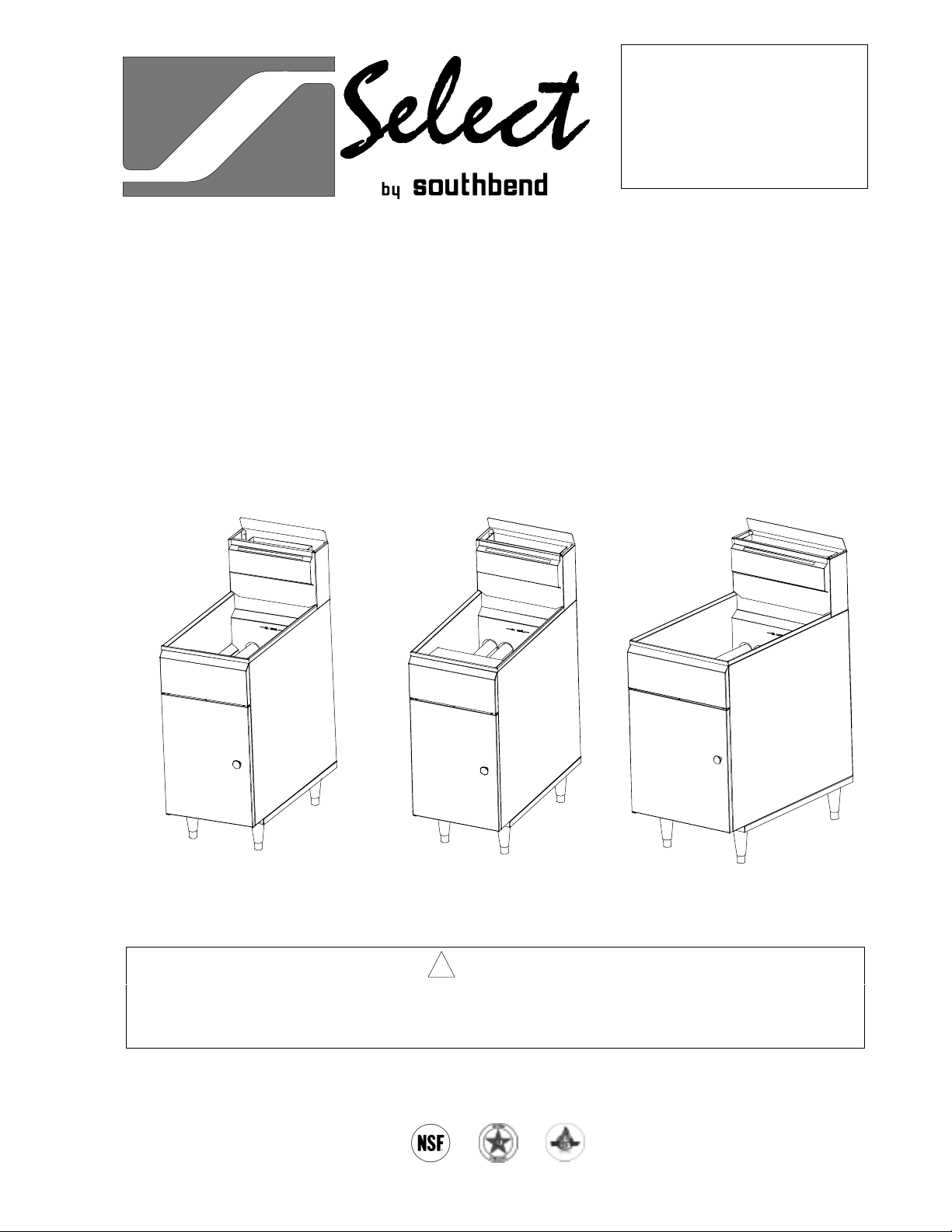
OPERATOR’S MANUAL
Free-Standing, Floor Model
GFS Series Tube Fryers
Model GFS35 Model GFS45 Model GFS65
! WARNING
Improper installation, adjustment, alteration, service or maintenance can cause property damage,
injury or death. Read the installation, operating and maintenance instructions thoroughly before
installing or servicing this equipment.
1100 Old Honeycutt Road, Fuquay-Varina, NC 27526
(800) 348-2558 or (919) 552-9161 • FAX (800) 348-2558 or (919) 552-9798
MANUAL 1182026 REV 2
$10.00
GFS SERIES TUBE FRYERS
MANUAL SECTION SR
Page 2

Safety Precautions
PAGE 2OPERATOR’S MANUAL 1182026 REV 2
Page 3

GFS SERIES TUBE FRYERS TABLE OF CONTENTS
OPERATOR’S MANUAL 1182026 REV 2PAGE 3
Page 4
SPECIFICATIONS GFS SERIES TUBE FRYERS
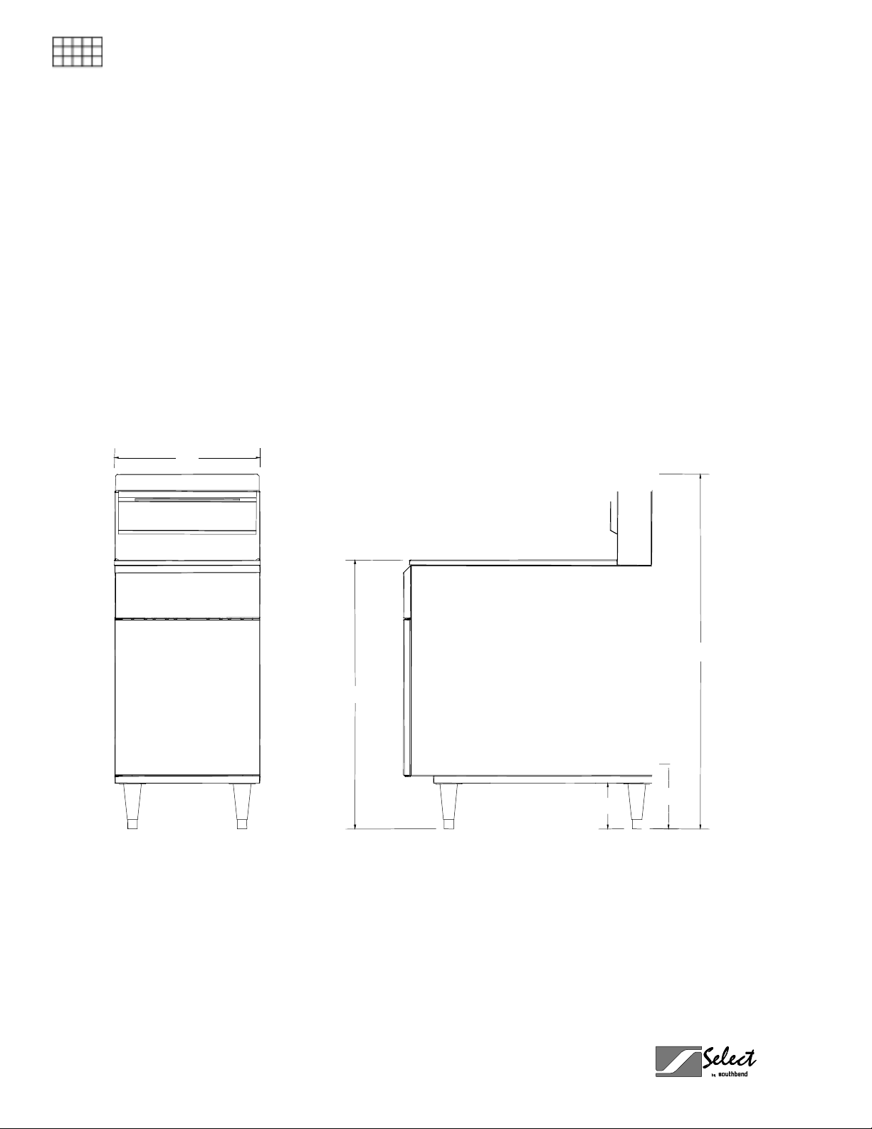
SPECIFICATIONS
SPECIFICATIONS
Dimensions
PAGE 4OPERATOR’S MANUAL 1182026 REV 2
Page 5
GFS SERIES TUBE FRYERS SPECIFICATIONS
Gas Supply Requirements and Burner Information
Supply pressure should be greater t han 7" W.C. for natural gas or greater than 11" W .C. for propane. One
3/4" NPT male connector located on back (see illustrations on pages 4 and 7).
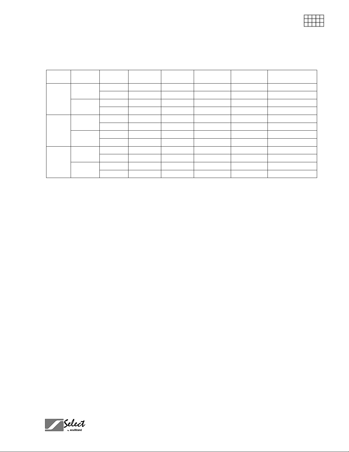
SPECIFICATIONS
Model Burners Gas Type
Main
GFS35
Pilot
Main
GFS45
Pilot
Main
GFS65
Pilot
Natural 4" W.C. 3 35,000 105,000 #36 - 0.1065" dia.
Propane 10" W.C. 3 30,000 90,000 #52 - 0.0635" dia.
Natural 4" W.C. 1 900 900 #77 - 0.0180" dia.
Propane 10" W.C. 1 900 900 0.0110" dia.
Natural 4" W.C. 4 35,000 140,000 #36 - 0.1065" dia.
Propane 10" W.C. 4 30,000 120,000 #52 - 0.0635" dia.
Natural 4" W.C. 1 900 900 #77 - 0.0180" dia.
Propane 10" W.C. 1 900 900 0.0110" dia.
Natural 4" W.C. 5 35,000 175,000 #36 - 0.1065" dia.
Propane 10" W.C. 5 30,000 150,000 #52 - 0.0635" dia.
Natural 4" W.C. 1 900 900 #77 - 0.0180" dia.
Propane 10" W.C. 1 900 900 0.0110" dia.
Manifold
Pressure
Electrical Requirement
No external electric power is required.
Clearances
See page 9.
Number
per Unit
Rate Each
BTUs/Hour
Total Rate
BTUs/Hour
Orifice Size
OPERATOR’S MANUAL 1182026 REV 2PAGE 5
Page 6
INSTALLATION GFS SERIES TUBE FRYERS
INSTALLATION
Installation mu st conform with local codes, or in the absence of local codes , with the National Fue l
Gas Code, ANSI Z223.1, Natural Gas Installation Code, CAN/CGA-B149.1, or the Propane
Installation Code, CAN/CGA-B149.2, as applicable.
INSTALLATION
These installation procedures must be followed by qualified personnel or warranty will be void.
Local codes regarding install ation var y greatly from one area to an other. T he National F ire Protec tion
Association, Inc. states in its NFPA 96 latest edition that local codes are the “authority having
jurisdiction” when it comes to installation requirements for equipment.
NOTICE
NOTICE
Step 1: Unpack
IMMEDIATELY INSPECT FOR SHIPPING DAMAGE
All containers shou ld be examined for dam age before and during unlo ading. The freight car rier has
assumed responsibility for safe transit and delivery. If damaged equipment is received, either
apparent or concealed, a claim must be made with the delivering carrier.
Apparent damage or l oss m u st be noted on the freight b ill at the t im e of deliver y. T he f reight bi ll m ust
then be signed by the c arrier representative (Dr iver). If the bill is not signed, the carrier ma y refuse
the claim. The carrier can supply the necessary forms.
A request for insp ection must be m ade to the carrier within 15 da ys if there is concea led damage or
loss that is not apparent until after the equipment is uncrated. The carrier should arrange an
inspection. Be certain to hold all contents plus all packing material.
1. Uncrate carefully. Report any hidden damage to the freight carrier IMMEDIATELY.
2. Do not remove any tags or labels until unit is installed and working properly.
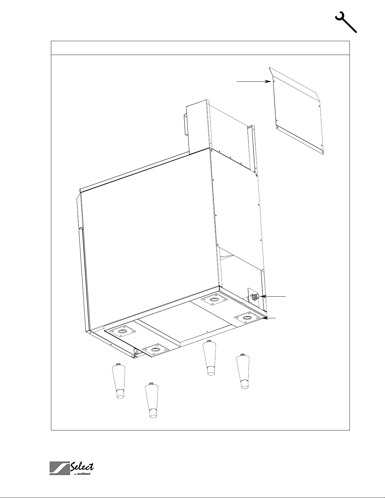
Step 2: Install Flue Riser
The flue riser assembl y is packed separately in the f ryer shipping crate. Att ac h t he f lue ris er to the top rear of
the fryer (see illustration on page 7).
PAGE 6OPERATOR’S MANUAL 1182026 REV 2
Page 7
GFS SERIES TUBE FRYERS INSTALLATION
Installation
Flue Riser
INSTALLATION
Gas Connection
Leg Attachment Pad
OPERATOR’S MANUAL 1182026 REV 2PAGE 7
Page 8
INSTALLATION GFS SERIES TUBE FRYERS
Step 3: Install the Legs (or Casters) and Restraints
A set of legs or casters is packed with the fryer. A threaded pad is fastened to the base frame at each corner
(see illustration on page 7). Each leg or caster has a similar mating thread. When casters have been
ordered, the casters are provided with a Zerk fitting for proper lubrication when required.
1. Raise fryer sufficientl y to allow legs or cas ters to be screwed into the pads. For s afety, “shore up” an d
support the fryer with an adequate blocking arrangement strong enough to support the load.
2. Screw the four legs or caster s to the pads o n the bottom of the f ryer. W hen cas ters have bee n ordered,
the casters having a locking-brake should be attached under the front of the fryer.
3. Lower the fryer gently. Never drop or allow the fryer to fall.
4. Use a level to make sure that the fryer is level. Each caster, or the tubular-end of each leg, can be
INSTALLATION
screwed in or out to lower or raise each c orner of the fryer. For f ryers having casters, t ighten the lock
nuts after the unit has been leveled.
5. Attach r est raints as requir ed b y loca l code s.
NOTICE
Unit must be level to assure maximum performance. Improper leveling may void warranty.
NOTICE
Adequate restraining means must be attached to rear of appliance when installed. Installation must
conform to local codes as applicable.
! WARNING
If disconnection of the restraint is necessar y to move the appliance for cleaning, etc., reconnect it
when the appliance is moved to its original installed position.
! WARNING
For an appliance e quipp ed with cas ter s, the ins tall ation sh all b e m ade with a co nnector that com plies
with the Standard for Connectors for Movable Gas Appliances, ANSI Z21.69 or Connectors for
Moveable Gas Appliances, CAN/CGA-6.16, and a quick-disconnect device that complies with the
Standard for Quick-Disconnect Devices for Use With Gas Fuel, ANSI Z21.41, or Quick Disconnect
Devices for Use with Gas Fuel, CAN1-6.9. Adequate means must be provid ed to lim it the m ovement
of the appliance without depending on the connector and the quick-disconnect device or its
associated piping to limit the appliance movement.
! WARNING
All GFS Series Fryers must be restrained to prevent t ipping in order to a void the splashing of hot
liquid. The means of restraint m ay be the manner of installat ion, such as connection to a battery of
appliances or installing the fryer in an alcove, or by separate means, such as adequate ties.
PAGE 8OPERATOR’S MANUAL 1182026 REV 2
Page 9
GFS SERIES TUBE FRYERS INSTALLATION
Step 4: Check Clearances and Ventilation
Select a firm, level loc ation for your Southb end fryer. Leave clear ance, whenever possible, s o that access
from the rear is possible to permit clean ing. If the unit is to be s et on non-combustible floor ing, such as a
concrete slab, 3 inches minim um toe room must be provided t o prevent restriction of t he air opening in the
bottom of the unit.
! WARNING
There must be adequate clearance between fryer(s) and construction. Clearance must also be
provided in front for servicing and for operation.
Minimum Clearances:
From Combustible Construction From Non-Combustible Construction
Sides 7" 0"
Rear 7" 0"
ALL GFS SERIES FRYERS SHALL BE INSTALLED WITH AT LEAST A 16 INCH SPACE BETWEEN
THE FRYER AND SURFACE FLAMES FROM ADJACENT EQUIPMENT.
No additional side and rear clearance is required for service as the fryer is serviceable from the front.
INSTALLATION
! WARNING
Improper ventilation can result in personal injury or death. V ent il ation that fails to properly remove flue
products can cause headaches, drowsiness, nausea, or could result in death.
All units must be installed in such a manner that the flow of combustion and ventilation air is not
obstructed. Provisions for adequate air supply must also be provided. Do NOT obstruct the bottom
front of the unit, as combustion air enters through this area. Be sure to inspect and clean the
ventilation system according to the ventilation equipment manufacturer’s instructions.
NOTICE
Proper ventilation is t he owner’s responsibility. An y problem due to improper venti lation will not be
covered by the warranty.
Due to the variety of problems that c an be ca us ed b y outside weather condit io ns , ve nt ing by canopies or wall
fans is preferred over any type of direct venting. It is recommended that a canopy extend 6" past the
appliance and the bottom edge be located 6'6" from the floor. Filters should be installed at an angle of 45° or
more from the horizontal. This position prevents dripping of grease and facilitates collecting the run-off
grease in a drip pan, unusually install ed with a filter. A strong exha ust fan tends to creat e a vacuum in the
room and may interfere with burner performance or may extinguish pilot flames. Fresh air openings
approximately equal to the fan area will relieve such a vacuum . In case of unsatisfactor y performance on
any appliance, chec k the appliance with the exhaust f an in the “OFF” position. Do th is only long enough to
check equipment perform ance, then turn hood bac k on and let it run to remove any exhaus t that may have
accumulated during the test.
The exhaust fan should be installed at least 2 feet above the vent opening at the top of the fryer.
This unit is not intended to be connected directly to an outside flue.
OPERATOR’S MANUAL 1182026 REV 2PAGE 9
Page 10
INSTALLATION GFS SERIES TUBE FRYERS
Step 5: Gas Connection
A 3/4" male NPT line for the gas connection is located near the lower left rear corner of the fryer (see
illustration on page 7). T he ser i al pla te (l oc ate d i nsid e th e f r ont do or of the f ryer) indicates the type of gas th e
unit is equipped to burn (natural gas or propa ne). The f ryer shou ld be c onnec ted O NLY t o the t ype of gas f or
which it is equipped.
A millivoltage circuit diagram is located inside the front door of the fryer.
All Southbend equ ipment is adjusted at the f actory; however, pilot he ight should be c hecked at instal lation
and adjusted, if necessary (see page 22).
For orifice sizes and pressure regulator settings, see the chart on page 5. If the fryer is being installed at over
2,000 feet altitude and that inform ation was not specified when order ed, contact the appropr iate authorized
Southbend Service Representative or the Southbend Service Department. Failure to install with proper
orifice sizing will result in poor performance and may void the warranty.
INSTALLATION
If applicable, the ven t line from the gas appliance pressure regulator shall be installed to the outdoors in
accordance with local codes or, in the absence of local codes, with the National Fuel Gas Code, ANSI
Z223.1, Natural Gas Installation Code, CAN/CGA-B149.1, or the Propane Installation Code, CAN/CGAB149.2, as applicable.
An adequate gas supply is imperative. Undersized or low pressure lines will restrict the volume of gas
necessary for satisfac tory performance. A com bination gas valve an d pressure regulator, which is provide d
with each unit, is set to maintain a 4 " W.C. manifold press ur e f or natur al gas or 1 0.0 " W.C. manifold press ur e
for propane gas. However, to mainta in these conditions the press ure on the supply line, wh en all units are
operating simultaneously, should not drop below 7" W.C. for natural gas or 11" W.C. for propane gas.
Fluctuations of m ore than 25% on nat ural gas or 1 0% on pr opan e gas will cr eate pro blem s and aff ect bur ner
operating characteristics. A 1/8" tap to measure the manifold pressure is located on the combination gas
valve, which is on the burner manif old loca ted dir ectly below the burners inside t he cabin et.
Purge the supply line to clean out dust, dirt, or other foreign matter before connecting the line to the unit.
It is recommended that an individual manual shutoff valve be installed in the gas supply line to the unit.
Use pipe joint compound that is suitable for use with both natural and LP gas on all threaded connections.
! CAUTION
ALL PIPE JOINTS AND CONNECTIONS MUST BE TESTED THOROUGHLY FOR GAS LEAKS.
USE ONLY SOAPY W ATER FOR TESTING O N ALL GASES. NEVER USE AN O PEN FLAME T O
CHECK FOR GAS LEAK S. ALL CONNECTIONS MUST BE CHEC KED FOR LEAKS AFTER T HE
UNIT HAS BEEN PUT INTO OPERATION. TEST PRESSURE SHOULD NOT EXCEED 14" W.C.
! CAUTION
THIS APPLIANCE AND ITS INDIVIDU AL COMBINATION GAS VALV E MUST BE DISCONNE CTED
FROM THE GAS SUPPLY PIPING SYSTEM DURING ANY PRESSURE TESTING OF THAT
SYSTEM AT TEST PRESSURES IN EXCESS OF 1/2 PSIG (3.45 kPa).
The appliance must be isola ted from the gas supply pipin g system by closing its individ ual manual
shutoff valve during any pressur e testing of the gas suppl y piping system at test pres sur es eq ua l to or
less than 1/2 psi (3.45 kPa).
Connect the gas suppl y direc tly to th e 3/4" m ale NPT connector locat ed near the lower left r ear corn er of the
fryer. When tighten ing the s u pp l y pipe, be s ure to hol d th e mating connector exten din g from the unit sec ure ly
with a wrench. This will prevent any damage or distortion to the internal piping and controls of the unit.
After connecting the gas suppl y, check again that the fryer is level. Use a long spirit lev el four ways; ac ross
the front and rear of the frypot, and along each edge.
PAGE 10 OPERATOR’S MANUAL 1182026 REV 2
Page 11

GFS SERIES TUBE FRYERS INSTALLATION
! CAUTION
IF YOU SMELL GAS DURING THE LIGHTING PROCE DURE, I MMEDIAT ELY SHUT OFF THE GAS
INSTALLATION
OPERATOR’S MANUAL 1182026 REV 2PAGE 11
Page 12
OPERATION GFS SERIES TUBE FRYERS
OPERATION
NOTICE
These procedures mus t be followed b y qual if ied pers onn el or warranty will be voided.
All Southbend GFS Series Tube Fryers are immersion tube fryers. This is the most efficient method of
transmitting heat int o the oil. T he tubes are actu ally large h eat exc hangers. Eac h tub e is heated by a burner
at its front that propels its flame and heat into the tube , toward the rear, where it is vented into a flue box .
The combined heat tr ansfer area of the tubes is m uch greater than the other t ypes using element c oils or
under-fired pots. Consequent ly, heat transf er per square inch is lower, as is the tem perature, but beca use of
the increased surf ace area, immers ion tube fryers transf er more heat into the oil. The lo wer temperature of
the heating surfac e prevents scorching and carbonizatio n of the oil. Higher heat trans fer rate gives faster
recovery between loads.
Another advantage of immersion tube fryers is the cold zone. As oil is heated it passes between and over the
tubes and rises int o the frying zone, where it imparts heat into the pr oduct. After gi ving up heat , it des cends
to the cooler zone be low the tub es. Foo d particl es and cr umbs are dropped and trap ped in the cold zone as
the oil awaits to be recirculated. The cold zone concept helps keep the oil circulating and clean of debris.
OPERATION
! WARNING
BURN HAZARD
Contact with hot oil will cause sever e b urns . Al ways use caution. Oil at 2 00 °F is more dangerous than
boiling water.
! CAUTION
NEVER OPERATE THE FRYER WITHOUT SUFFICIENT OIL TO COVER THE TUBES.
Lighting
! CAUTION
IF YOU SMELL GAS DURING THE LIGHTING PROCE DURE, I MMEDIAT ELY SHUT OFF THE GAS
SUPPLY UNTIL THE LEAK HAS BEEN CORRECTED.
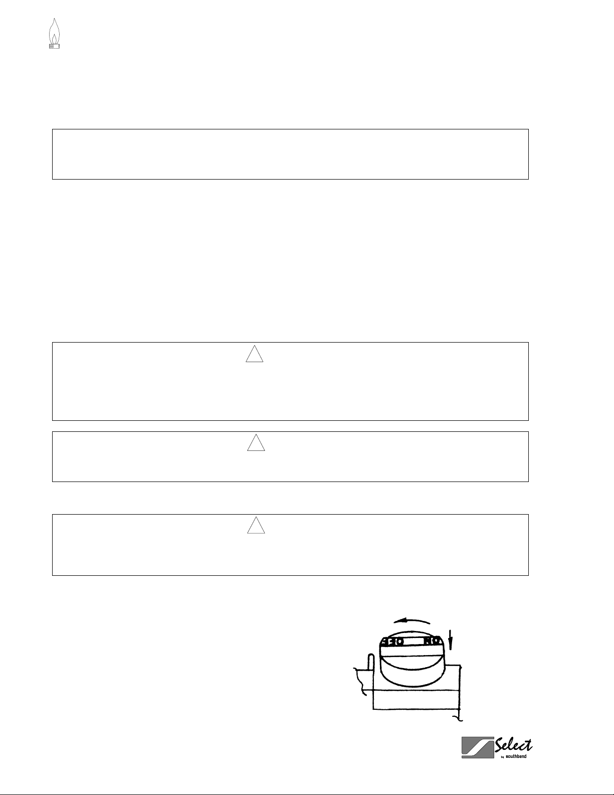
Open the burner compartment door and do the following:
1. Turn thermostat to “OFF” (lowest position).
2. Press down the knob of the combination gas
valve, turn it counterclockwise to the “PILOT”
position, and continue to press the knob down.
PAGE 12 OPERATOR’S MANUAL 1182026 REV 2
Page 13

GFS SERIES TUBE FRYERS OPERATION
3. W hile pressing the knob down, us e a lit match to ignite the pilot. Continue to press the knob d own for
about 30 seconds. If the pilot does not stay ignited when the knob is released, repeat the lighting
procedure and keep the knob down longer. Adjustment of pilot flame may be necessary.
4. W hen the pilot sta ys ignit ed, turn t he k nob cou ntercl ock wise to the “ON” pos ition . Do not press down o n
the knob in this step.
5. Do NOT turn the thermostat “ON” until the frypot is filled with oil or solid shortening.
Shutdown Procedure
Standby: Turn knob on the combination gas valve to the “PILOT” position. At this setting, only the pilot
burner will remain ignited.
Complete Shutdown: Turn knob on the com bination gas val ve, then press d own on the knob and co ntinue
to turn to the “OFF” position.
Relighting
! WARNING
In the event of a m ain burner ignitio n f ailure, a five m inute purge peri od m us t be obser ved prior to reestablishing the ignition source.
OPERATION
1. Shut off all gas.
2. Wait five minutes.
3. Follow the “Lighting” procedure described on page 12.
Filling the Frypot
1. Close drain valve completely before filling the frypot.
2. When the fryer is new, fill t he f r ypot with water a nd c lean thoroughly (see “Weekly Cleaning” on pag e 18)
in order to remove protective coatings and any foreign matter.
3. T he recommended solid shortening capaci t y for the fry pot is 35 pounds for Model GFS35, 45 p oun ds f or
Model GFS45, and 65 pounds for Model GFS65.
4. Remove the basket support frame when filling the frypot with solid shortening.
OPERATOR’S MANUAL 1182026 REV 2PAGE 13
Page 14

OPERATION GFS SERIES TUBE FRYERS
Automatic Pilot Valve
The Automatic Pilot Valve provides an automatic safety shutoff for the fryer when the pilot flame is
extinguished. When the pilot flam e is burning, the valve is held open electromagnetically by the electrical
current from a thermopile in the pilot flam e. When the pi lot flam e goes out, generation of cur rent ceases an d
the valve closes automatically.
High Limit Control
The GFS Series Tube Fr yers are equipped with a secondary heat contro l that prevents the oil temperature
from rising above 450°F. (Bec ause of the accurac y tolerance of the se nsor, the oil tem perature may reach
as high as 475°F.)
In the event the fryer shuts down due to th is con ditio n, the o il m ust be c oole d to be low 400 °F bef ore t he pi lot
burner can be re-ignited. When the oil has cooled, use the “Lighting” procedure on p ag e 12 to pl ace th e fryer
back in operation. If the prob lem pers ists, contact your Southb end Ser vice Re presentati ve or the S outhbend
Service Department.
! WARNING
In the event a gas odor is de tected, shut down equ ipment at the com bination gas valv e and contact
the local gas company or gas supplier for service.
OPERATION
PAGE 14 OPERATOR’S MANUAL 1182026 REV 2
Page 15

GFS SERIES TUBE FRYERS COOKING HINTS
COOKING HINTS
User Tips
• Smoking oil means that the temperature is too high, or that the oil has broken down.
• Gum in frypot denotes a need for thorough cleaning (see “Weekly Cleaning” on page 18)
• Use different oil for oily foods (mackerel, nutmeg, etc.) than for foods with water-soluble flavors
(potatoes, onions, etc.).
• Taste oil for quality. Replace it regularly.
• Poor oil cannot produce good food.
Gas Saving Tips
Use the following tips to help dev elop energy-saving proce dures and habits. Using les s natural or propane
gas saves energy, and money, too.
• Limit preheat time to 5 to 10 minutes.
• Set thermostat to desired temperature.
• Do not overheat. Never use temperatures higher than 375°F.
• Turn fryers off during slack periods.
• Filter oil daily. Clean frypot thoroughly at least once a week (see page 18).
COOKING HINTS
Frying Do’s
• Make sure frypot is clean.
• Make sure thermostats are registering and functioning properly.
• Fill frypot only to proper frying level. An oil-level line is stamped on the frypot.
• Maintain proper level of oil in the frypot b y occasionall y adding fresh solid sh ortening as the fr ypot fries
down.
• Keep heating tubes covered at all times when heat is on.
• Fry at temperature in the range 325°F to 375°F.
• Turn heat in the fr ypots to 200°F, or preferably off, between fry periods, or during any periods of time
when this is practical.
• Fry foods in amounts onl y up to a f ull loa d; a f ull loa ding b eing t he point where t he tem peratur e r ecover s
to the dial setting and the thermostat turns off the burner before the food is completely fried or done.
• Remove food bask ets from frypot as soo n as food is done, allowing f ood to dra in over f rypot a m inimum
of 30 seconds.
• Keep oil as clean as possible at all times, removing immediately any floating burned particles.
• Make sure baskets are sound and don’t leak food into the frypot.
• Drain frypot, filter oil, and remove all residue from cold zone at least once daily. Boil out frypot and
baskets with detergent at least once a week, scraping off any foreign materials not yielding to the
treatment. Rinse fr ypot several tim es by filling with fr esh water and bringing t o boil. Perform the weekly
cleaning procedure (see page 18).
• Keep frypots covered when not in use.
OPERATOR’S MANUAL 1182026 REV 2PAGE 15
Page 16

COOKING HINTS GFS SERIES TUBE FRYERS
Frying Don’ts
• Don’t turn on the fryer with no shortening in the frypot.
• Don’t fill the frypot above the line on rear of frypot.
• Don’t allow oil in frypot to fry down to the point where there is insufficient oil in which to fry a full load.
• Don’t have heat on tubes when they are not entirely covered with frying oil.
• Don’t allow oil in f rypot to be heated above 375°F and never tur n thermostats to 400°F or over, even
when bringing up the temperature.
• Don’t allow unnecessary moisture or breading materials to get into frypot.
• Don’t allow oil in frypot to remain at frying temperature for long periods of time without frying taking
place.
• Don’t overload frypot with food to be fried.
• Don’t pack the food too tightly in the baskets.
• Don’t add foreign oils to frypot such as bacon, beef drippings, or waste oil.
• Don’t fry bacon in frypot.
• Don’t salt food over or near the frypot.
• Don’t allow visible burned particles to remain floating in frypot.
• Don’t allow exhaust stack accumulations to drip back into the frypot.
Performance
Potatoes — Raw to Finished 65-70 lbs. per hour 100-105 lbs. per hour 115-120 lbs. per hour
COOKING HINTS
Chicken — Raw to Finished 40-45 lbs. per hour 50-55 lbs. per hour 55-60 lbs. per hour
Typical Production Model GFS35 Model GFS45 Model GFS65
— Blanched to Finished 280-285 lbs. per hour 320-325 lbs. per hour 355-360 lbs. per hour
— Blanched to Finished 80-85 lbs. per hour 95-100 lbs. per hour 105-110 lbs. per hour
PAGE 16 OPERATOR’S MANUAL 1182026 REV 2
Page 17

GFS SERIES TUBE FRYERS CLEANING
CLEANING
Southbend equipment is constructed with the best quality materials and is designed to provide durable
service when properl y maintained. To expect the b est performance, your equipment must be m aintained in
good condition and cleaned dail y. Naturally, the frequenc y and extent of cleaning depends on the amount
and degree of usage.
Following daily and more extensi ve peri odic maintenance proced ur es will incr e as e th e l if e of your equ ipment.
Climatic conditions (e.g., sal t air) may result in the need for more thorough and m ore frequent cleaning in
order to keep equipment performing at optimal levels.
! WARNING: BURN HAZARD
If necessary to move the fryer for cleaning, etc., drain oil first to avoid death or serious injury.
NOTICE
Adequate restraining means must be attached to rear of appliance when installed. Installation must
conform to local codes as applicable.
! WARNING
If disconnection of the restraint is necessar y to move the appliance for cleaning, etc., reconnect it
when the appliance is moved to it origin al l y inst alled pos it io n.
! WARNING
For an appliance e quipp ed with cas ter s, the ins tall ation sh all b e m ade with a co nnector that com plies
with the Standard for Connectors for Movable Gas Appliances, ANSI Z21.69 or Connectors for
Moveable Gas Appliances, CAN/CGA-6.16, and a quick-disconnect device that complies with the
Standard for Quick-Disconnect Devices for Use With Gas Fuel, ANSI Z21.41, or Quick Disconnect
Devices for Use with Gas Fuel, CAN1-6.9. Adequate means must be provid ed to lim it the m ovement
of the appliance without depending on the connector and the quick-disconnect device or its
associated piping to limit the appliance movement.
Daily Cleaning
1. Turn combination gas valve knob to “PILOT” position.
2. Place suitable container under the drain and drain the frypot completely.
3. Remove the basket support frame and flush out any sediment remaining in the frypot with a little hot oil.
4. Wipe off the basket support frame and the inside of the frypot with a clean cloth.
CLEANING
! CAUTION
SOME AREAS OF THE FRYPOT MAY BE HOT!
OPERATOR’S MANUAL 1182026 REV 2PAGE 17
Page 18

CLEANING GFS SERIES TUBE FRYERS
5. Close drain valve and strain the oil back into the fr ypot through several thick nesses of cheesec loth, or
filter it back using a filter machine.
CLEANING
PAGE 18 OPERATOR’S MANUAL 1182026 REV 2
Page 19

GFS SERIES TUBE FRYERS CLEANING
Darkened areas, call ed “heat tint,” sometim es appear on stainless st eel surfaces wher e the area has been
subjected to excessive heat. Thes e dark ened areas are caus ed b y thick ening of the pr otec tive sur face of the
stainless steel and are not harmful. Heat tint ca n normally be rem oved by the above cleanin g techniques, but
tint which does not r espon d to that proced ure ca lls f or a v igorous scour ing in t he directi on of the pol ish l ines ,
using SCOTCH-BRITE scouring pads or a STAINLESS scouring pad in combination with a powered
cleanser. Heat tint act ion may be lessened b y not applying, or b y reducing, h eat to equipm ent during slack
periods.
OPERATOR’S MANUAL 1182026 REV 2PAGE 19
CLEANING
Page 20

SERVICE GFS SERIES TUBE FRYERS
f
SERVI CE
NOTICE
Warranty will be void and the manufacturer is relieved of all liability if:
(A) Service work is performed by other than a qualified technician,
OR
(B) Other than genuine Southbend replacement parts are installed.
! WARNING
Adjustments and service work may be performed only by a qualified technician who is experienced in,
and knowledgeable with, the operation of commercial gas cook ing equipment. However, to assure
your confidence, contact your Southbend Service Representative (or the Southbend Service
Department) for reliable service, dependable advice or other assistance, and for genuine factory
parts.
! WARNING
Appliances equipped with casters have been installed with a restraint to limit their movement to
prevent damage to the gas supply connecting system. If disconnection of this restraint is necessary to
move the appliance for cleaning, etc., reconnect it when the appliance is moved to its original
installed position.
Adjustments
All units are adjusted at the factory. In c ase of problem s in operation a t initial instal lation, check type of gas
and manifold pressure and compare with information listed on the serial plate.
Checking and Adjusting Main Burners
The main burners should burn with a steady blue
flame, and the inner cone of the flam e fr om eac h port
should be about 3/4" long . The f lam e from each m ain
burner should enter e ach heat tube wit hout touching
the front of the frypot or the s ides, top, or bottom o
each tube.
SERVICE
3/4"
Normal Flame
Blowing or Lifting Flames
(too much air)
Yellow Tips
(too little air or too much gas)
PAGE 20 OPERATOR’S MANUAL 1182026 REV 2
Page 21

GFS SERIES TUBE FRYERS SERVICE
r
Checking and Adjusting Pressure Regulator
The combination gas v alve and pres sure regulator is factor y set at 4" W .C. for natural gas and 10 " W .C. for
propane gas. To check the manifold pressure, do the following:
1. Turn thermostat “OFF” (lowest position) and combination gas valve knob to the “PILOT” setting.
2. Remove pressure tap plug from burner manifold located directly below the burners in the cabinet.
3. Install a fitting appropriate to connect a manometer.
4. Turn combination gas valve to “ON” positi on and thermostat to “ ON.” The burners will i gnite. Be certain
that sufficient oil is covering the tubes.
5. With burners on, read manometer.
6. If the manometer does not read 4" W.C. for natural gas, or 10" W.C. for propane gas, adjust regulator.
7. Remove regulator adjustment screw cap (see diagram on page 24).
8. With sm all screwdr iver rotate adjustm ent sc rew “CLOCKW ISE” to inc rease or “COUNT ERCLOCKW ISE”
to decrease pressure. Be sure to adjust with burners “ON.”
9. Turn thermostat “OFF” and set combination gas valve knob to “PILOT” position.
10. Remove manometer and replace pressure tap plug.
11. Replace adjustment screw cap.
Checking and Adjusting Calibration of Thermostat
All thermostat controls are car efull y calibrated at the f actory (i.e., the dial is pr operly set t o control a ppliance
temperatures accurately). Only a qualified appliance service technician should perform this adjustment.
1. To check appliance temperatures, use a thermocouple-type temperature test instrument or reliable
thermometer. Place the thermocouple of test instrument or thermometer in the center of the frypot.
2. Turn the control dial to the tem perature setting requiring the gre atest accuracy. Allow enough tim e for
temperature to stabilize, or until several temperature readings are identical.
3. Recalibrate if setting and actual temperature differ by more than 10°F.
4. Remove dial from dial shaft “B.” Be careful that
dial shaft does not rotate in either direction
(which would change the dial setting).
5. Hold dial shaft “B” steady and wit h a screwdriv e
turn calibration screw “ A” clockwise to decrease
the temperature, or counterclock wise to incr ease
the temperature.
6. Replace dia l. Let the appliance operate un til the
temperature has stabi lized bef ore a f inal check is
made to determine whether or not th e calibration
has been corrected.
7. Once correct, seal the calibration screw with
glyptol.
SERVICE
OPERATOR’S MANUAL 1182026 REV 2PAGE 21
Page 22

SERVICE GFS SERIES TUBE FRYERS
Checking and Adjusting Auto Safety Pilot
The pilot flame should surround the thermopile for 1/2". It m ust be large and sharp enough to cause the
thermopile to glow a dull red, or sufficient to hold the safety valve open.
1. Remove pilot adjustment cap (see wiring diagram on page 24 for location).
2. Adjust pilot key to provide properly sized flame.
3. Replace pilot adjustment cap.
Converting from Natural Gas to LP Gas
Obtain a natural-to-LP gas conversion kit (part number 4440493) from your authorized Southbend parts
distributor. The kit com es with five LP gas orifice spuds; M odel GFS65 uses all five s puds, model GFS45
uses four, and model GFS35 uses thre e. In the following proc edure, refer to the parts diagram on page 28
for Model GFS35, on page 30 for Model GFS45, or on page 32 for Model GFS65.
1. Remove the existing natur al gas spud from each burner and replace it with an LP gas spud f rom the
conversion kit.
2. Loosen the compression fitting at the pilot and remove the pilot tubing from the pilot.
3. Remove the two pilot mounting screws.
4. Remove the nat ural gas pilot orifice fr om the pilot and replace it with the LP gas pilot orifice fr om the
conversion kit.
5. Remount the pilot assembly, reposition the pilot tubing, and tighten the compression fitting.
6. Partially depress and turn the combination gas valve knob to “OFF.”
7. Remove the two screws that pass through the
regulator, the regulator, and the gasket (see
figure at right).
8. Install the new gasket and regulator from the
conversion kit using the two screws in the
conversion kit.
9. T urn the combination gas va lve knob to “PILOT ”
and light the pilot, then turn the knob to “ON.”
10. W ith the main burners on, test for leaks using a
soap solution.
11. Check and adjust the pressure regulator (see
procedure on page 21). The pres sure should be
10" W.C. for propane gas.
SERVICE
Regulator
Gasket
PAGE 22 OPERATOR’S MANUAL 1182026 REV 2
Page 23

GFS SERIES TUBE FRYERS SERVICE
Troubleshooting
Problem Likely Cause
Burners do not come on Gas supply to unit off.
Combination gas valve is in “OFF” or “PILOT” position.
Pilot not ignited.
Thermostat not “ON.”
Pilot will not stay ignited Combination gas valve is in “OFF” position.
Pilot gas not adjusted properly.
Gas supply to unit off.
Bad thermopile.
Dirty thermopile connections at combination gas valve or high limit.
Bad magnet assembly in combination gas valve.
Clogged orifice.
Draft condition.
Air in gas line.
Improper ventilation system.
Oil excessively hot.
Pilot produces carbon deposits Unit connected to wrong gas supply.
Pressure not adjusted correctly.
Pilot gas not adjusted correctly.
Burners produce carbon deposits Wrong size orifices.
Connected to wrong gas supply.
Pressure not adjusted correctly.
Flue obstructed.
NOTE: Vibrations or shock caus ed b y shaking or pou nding bask ets on to p surf ace or by s lamm ing door m a y
cause Hi-Limit Contro l Switch to open. If this condition persists , additional cushio ning may be added to t he
rubber grommets supporting this control to absorb these shocks.
SERVICE
OPERATOR’S MANUAL 1182026 REV 2PAGE 23
Page 24

SERVICE GFS SERIES TUBE FRYERS
Wiring Diagram
PILOT
THERMOPILE
ADJUSTMENT CAP
GAS INLET
PILOT GAS
PILOT
COMBINATION
GAS VALVE
COMPONENT
LEADS
REGULATOR
ADJUSTMENT
CAP
MAIN GAS
REGULATING
THERMOSTAT
LIMITING
THERMOSTAT
Notes:
1. High limit switch is set to 450°F.
2. Voltage measured across TP/TH and TP with main burner on should be greater than 100 mV.
SERVICE
PAGE 24 OPERATOR’S MANUAL 1182026 REV 2
Page 25

GFS SERIES TUBE FRYERS PARTS
PARTS
NOTICE
INSTALLATION OF OTHER THAN GENUINE SOUTHBEND PARTS WILL VOID T HE WARRANTY
ON THIS EQUIPMENT.
The serial plate is located inside the front door on the left side.
Replacement parts may be ordered either thr ough a Southbend Auth orized Parts Dis tributor or a S outhbend
Authorized Service Agency.
When ordering parts, please supply the Model Number, Serial Number, Part Number, and Description.
For parts not listed, consult a Southbend Authorized Parts Distributor or Southbend Authorized Service
Agency. Consult the Southbend Authori zed Parts/Servic e Distributor list f or the Authorized P arts supplier in
your area. If this list is not available, call Southbend at 1-800-348-2558 to obtain this list.
Index of Parts Diagrams
Page Number Description
26 Cabinet Parts for GFS35 and GFS45
27 Cabinet Parts for GFS65
28 Gas Train Parts for GFS35
30 Gas Train Parts for GFS45
32 Gas Train Parts for GFS65
34 Frypot Parts for GFS35
35 Frypot Parts for GFS45
36 Frypot Parts for GFS65
OPERATOR’S MANUAL 1182026 REV 2PAGE 25
PARTS
Page 26

PARTS GFS SERIES TUBE FRYERS
Cabinet Parts for GFS35 and GFS45
3
4
2
7
10
8
5
11
1
Key Part Number Qty Description
1 1-2849 1 Knob, Door
2 1182216 1 Cover Splasher Rear
3 1182212 1 Fry Panel
4 1182209 1 Splasher Spot Weld
5 1182205 1 Door
6 1182025 1 Bracket, Bot tom Doo r
7 1182024 1 Bracket, Top Door Weld Ass embly
8 1182016 1 Panel, Inner Door
* 1172650 1 Leg Pad
9 1178205 1 Leg, Black (set of four)
* 1174265 1 Casters (optional, set of four)
* 1174262 1 Earthquake Legs (optional, set of four)
10 1164133 1 Catch, Door
11 1164132 1 Door Striker
PARTS
* not shown on drawing.
PAGE 26 OPERATOR’S MANUAL 1182026 REV 2
6
9
Page 27

GFS SERIES TUBE FRYERS PARTS
Cabinet Parts for GFS65
7
6
2
8
4
11
3
10
1
5
Key Part Number Qty Description
1 1-2849 1 Knob, Door
2 1182246 1 Cover Flue Re ar
3 1182228 1 Door
4 1182031 1 Panel Inner Door
5 1182025 1 Bracket, Bot tom Doo r
6 1182024 1 Bracket, Top Door Weld Ass embly
7 1182008 1 Fry Panel
8 1182007 1 Splasher Wel d Assembly
* 1172650 4 Leg Pad
9 1178205 1 Leg, Black (set of four)
* 1174265 1 Casters (optional, set of four)
* 1174262 1 Earthquake Legs (optional, set of four)
10 1164133 1 Catch, Door
11 1164132 1 Door Striker
* not shown on drawing.
9
PARTS
OPERATOR’S MANUAL 1182026 REV 2PAGE 27
Page 28

PARTS GFS SERIES TUBE FRYERS
Gas Train Parts for GFS35
See drawing on following page.
Key Part Number Qty Description
1 P5239-4 1 Union, Blac k, 1/2"
2 1182155 3 Burner, F ryer, 6 inch
3 1182154 1 Thermopile
4 1182152 1 Valv e, Combination, Natural Gas
1182153 1 Valv e, Combination, LP Gas
5 1182151 1 Thermostat, Regulating
6 1182150 1 Thermostat, Limitin g
7 1182508 1 Bracket, Support
8 1182055 1 Bracket, Mani fold Support
9 1182047 1 Tubi ng Lower Pil ot
10 1182040 3 Orifice, Mai n, Natural Gas (#36)
1182043 3 Orifice, Main, Propane (#52)
11 1182034 3 Fitti ng, Gas Orif ice
12 1182028 1 Tube, Upper Pilot
13 1182018 1 Tube Flex Gas
14 1182014 1 Manifold, 3 Burner
15 1175216 1 Nipple, 1/2 x 4 -1/2, Blac k
16 1147007 1 Plug, Pipe Blac k. 1/8
17 1146909 2 Elbow, St. Black ., 1/2" 90 Deg
18 1146806 1 Nipple, Pipe, Clos e, Blac k, 1/2 Inch
19 1061298 1 Union, Brass
20 1054197 1 Pilot Ass embly, 0. 018, Natural Gas
* 1054111 1 Pilot Ori fice, Propane (0.011", orifice only)
21 1036604 3 Nut Air Collar
* 4440493 1 Natural-to-LP Gas Conversion Ki t
* not shown on drawing.
PARTS
PAGE 28 OPERATOR’S MANUAL 1182026 REV 2
Page 29

GFS SERIES TUBE FRYERS PARTS
Gas Train Parts for GFS35
See parts list on previous page.
10
21
11
15
14
2
20
3
17
12
1
13
16
19
4
9
8
6
7
OPERATOR’S MANUAL 1182026 REV 2PAGE 29
5
18
PARTS
Page 30

PARTS GFS SERIES TUBE FRYERS
Gas Train Parts for GFS45
See drawing on following page.
Key Part Number Qty Description
1 P5239-4 1 Union, Blac k, 1/2"
2 1182237 1 Manifol d, 4 Burner
3 1182155 4 Burner, F ryer, 6 I nch
4 1182154 1 Thermopile
5 1182152 1 Valv e, Combination, Natural Gas
1182153 1 Valv e, Combination, LP Gas
6 1182151 1 Thermostat, Regulating
7 1182150 1 Thermostat, Limitin g
8 1182058 1 Bracket, Support
9 1182056 1 Bracket, Mani fold Support
10 1182047 1 Tubing Lower Pil ot
11 1182040 4 Orifice, Mai n, Natural Gas (#36)
1182043 4 Orifice, Main, Propane (#52)
12 1182034 4 Fitti ng, Gas Orif ice
13 1182028 1 Tube, Upper Pilot
14 1182018 1 Tube Flex Gas
15 1175216 1 Nipple, 1/2 x 4 -1/2, Blac k
16 1147007 1 Plug, Pipe Blac k. 1/8
17 1146909 2 Elbow, St. Black ., 1/2" 90 Deg
18 1146806 1 Nipple, Pipe, Clos e, Blac k, 1/2 Inch
19 1061298 1 Union, Brass
20 1054197 1 Pilot Ass embly, 0. 018, Natural Gas
* 1054111 1 Pilot Ori fice, Propane (0.011", orifice only)
21 1036604 4 Nut Air Collar
* 4440493 1 Natural-to-LP Gas Conversion Ki t
* not shown on drawing.
PARTS
PAGE 30 OPERATOR’S MANUAL 1182026 REV 2
Page 31

GFS SERIES TUBE FRYERS PARTS
Gas Train Parts for GFS45
See parts list on previous page.
3
17
11
15
2
16
21
12
20
4
13
14
1
19
10
7
8
OPERATOR’S MANUAL 1182026 REV 2PAGE 31
6
9
18
5
PARTS
Page 32

PARTS GFS SERIES TUBE FRYERS
Gas Train Parts for GFS65
See drawing on following page.
Key Part Number Qty Description
1 P5239-4 1 Union, Blac k, 1/2"
2 1182243 1 Manifol d, 5 Burner
3 1182155 5 Burner, F ryer, 6 I nch
4 1182154 1 Thermopile
5 1182152 1 Valv e, Combination, Natural Gas
1182153 1 Valv e, Combination, LP Gas
6 1182151 1 Thermostat, Regulating
7 1182150 1 Thermostat, Limitin g
8 1182058 1 Bracket, Support
9 1182057 1 Bracket, Mani fold Support
10 1182047 1 Tubing Lower Pil ot
11 1182040 5 Orifice, Mai n, Natural Gas (#36)
1182043 5 Orifice, Main, Propane (#52)
12 1182034 5 Fitti ng, Gas Orif ice
13 1182028 1 Tube, Upper Pilot
14 1182018 1 Tube Flex Gas
15 1175216 1 Nipple, 1/2 x 4 -1/2, Blac k
16 1147007 1 Plug, Pipe Blac k. 1/8
17 1146909 2 Elbow, St. Black ., 1/2" 90 Deg
18 1146806 1 Nipple, Pipe, Clos e, Blac k, 1/2 Inch
19 1061298 1 Union, Brass
20 1054197 1 Pilot Ass embly, 0. 018, Natural Gas
* 1054111 1 Pilot Ori fice, Propane (0.011", orifice only)
21 1036604 5 Nut Air Collar
* 4440493 1 Natural-to-LP Gas Conversion Ki t
* not shown on drawing.
PARTS
PAGE 32 OPERATOR’S MANUAL 1182026 REV 2
Page 33

GFS SERIES TUBE FRYERS PARTS
OPERATOR’S MANUAL 1182026 REV 2PAGE 33
PARTS
Page 34

PARTS GFS SERIES TUBE FRYERS
Frypot Parts for GFS35
2
1
3
Key Part Number Qty Description
1 1182262 3 Baffl e Weld Assembl y
2 1182258 1 Frypot Wel d Assembly
3 1182238 1 Valv e, Ball , 1-1/4 in
* 1036618 1 Thermostat Bulb Clamp
* 1140700 1 Screen, Tube Covering
* P9181 2 Basket, Si ngle
* 1176845 1 Drain Pi pe Exte nsion
* 1176846 1 Clean Out Rod (optional)
* not shown on drawing.
PARTS
PAGE 34 OPERATOR’S MANUAL 1182026 REV 2
Page 35

GFS SERIES TUBE FRYERS PARTS
Frypot Parts for GFS45
OPERATOR’S MANUAL 1182026 REV 2PAGE 35
PARTS
Page 36

PARTS GFS SERIES TUBE FRYERS
Frypot Parts for GFS65
2
Key Part Number Qty Description
1 1182238 1 Valv e, Ball , 1-1/4 in
2 1182021 5 Baffl e Weld Assembl y
3 1182005 1 Frypot Wel d Assembly
* 1036618 1 Thermostat Bulb Clamp
* 1140701 1 Screen, Tube Covering
* P9183 2 Basket, Si ngle
* 1176845 1 Drain Pi pe Exte nsion
* 1176846 1 Clean Out Rod (optional)
* not shown on drawing.
3
1
PARTS
PAGE 36 OPERATOR’S MANUAL 1182026 REV 2
Page 37

GFS SERIES TUBE FRYERS
OPERATOR’S MANUAL 1182026 REV 2PAGE 37
Page 38

GFS SERIES TUBE FRYERS
FREE-STANDING, FLOOR MODEL
GFS SERIES TUBE FRYERS
A product with the So uthbend name incor porates the best in dur ability and low m aintenance. We
all recognize, however, that replacement parts and occasional professional service may be
necessary to extend the useful life of this unit. When service is needed, contact a Southbend
Authorized Service Agenc y, or your dea ler. T o a void conf usion, alwa ys refer to the m odel num ber ,
serial number, and type of your unit.
Southbend
1100 Old Honeycutt Road, Fuquay-Varina, NC 27526
(800) 348-2558 or (919) 552-9161 • FAX (800) 348-2558 or (919) 552-9798
PAGE 38 OPERATOR’S MANUAL 1182026 REV 2
 Loading...