

Page 1
COMPARTMENT STEAMER
GAS BOILER
(Manual Section CS)
OWNER’S MANUAL
INSTALLATION
USER'S GUIDE
SERVICE
PARTS
COMPARTMENT STEAMER
GAS BOILER
MODELS: GC-2S; GC-3S; GDA-2S; CQ-325S
(250,000 BTU BOILER)
These instructions should be read thoroughly before attempting installation.
Set up, installation and Performance Check should be performed by a
qualified service technician. The Manufacturer, Southbend (1100 Old
Honeycutt Rd., Fuquay-Varina, North Carolina 27526), informs you that
unless the installation instructions for the above described Southbend product
are followed and performed by a qualified service technician, (a person
experienced in and knowledgeable concerning the installation of commercial
gas and/or electrical cooking equipment) then the terms and conditions of the
Manufacturer's Limited Warranty will be rendered void and no warranty of any
kind shall apply.
If the equipment has been changed, altered, modified or repaired by other
than a qualified service technician during or after the 12-month limited
warranty period, then the manufacturer shall not be liable for any incidental or
consequential damages to any person or to any property which may result
from the use of the equipment thereafter. Some States do not allow the
exclusion or 'imitation of incidental or consequential damages, so the above
limitation or exclusion thereto may not apply to you.
In the event you have any question concerning the installation, use, care, or
service of the product, write Customer Service Department, Southbend
Corporation, 1100 Old Honeycutt Rd., Fuquay-Varina, North Carolina 27526.
A MIDDLEBY COMPANY
Page 2
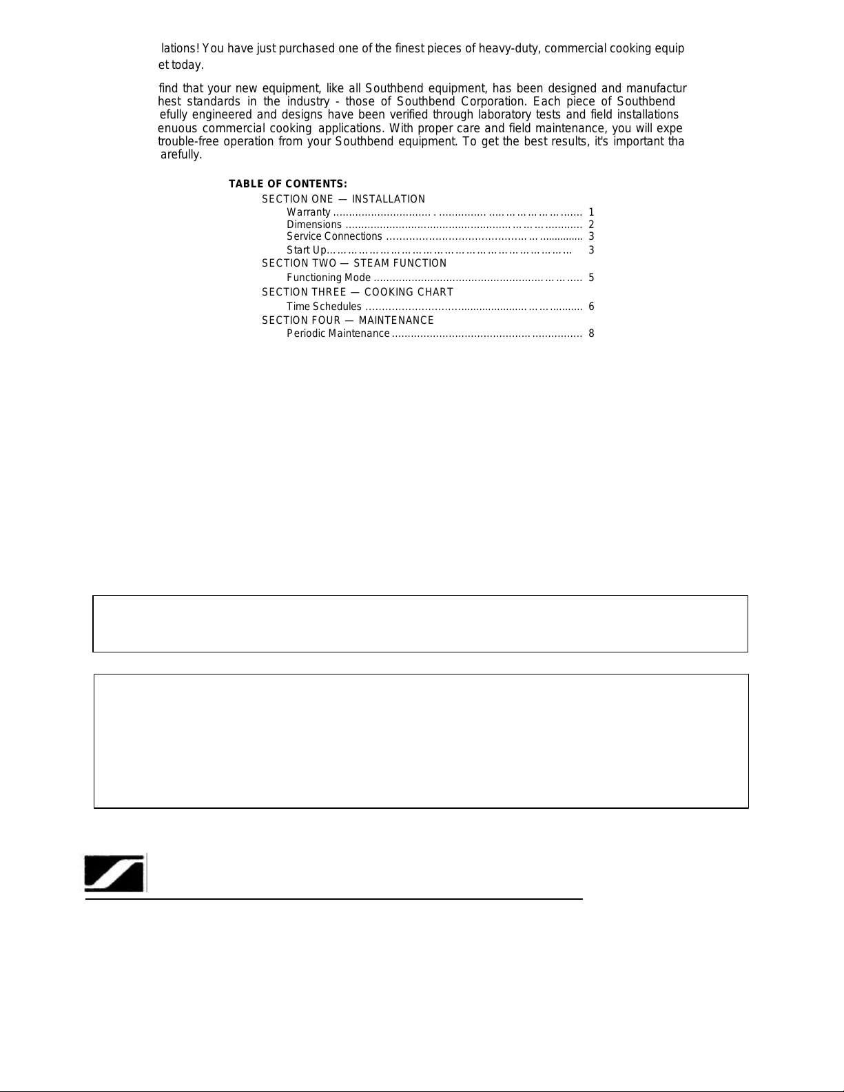
Warranty
............................... . ............... ..……………….......
1
Dimensions
..................................................…………............
2
SECTION SIX
— SERVICE
A MIDDLEBY COMPANY
Congratulations! You have just purchased one of the finest pieces of heavy-duty, commercial cooking equipment on
the market today.
You will find that your new equipment, like all Southbend equipment, has been designed and manufactured to some of
the toughest standards in the industry - those of Southbend Corporation. Each piece of Southbend equipment has
been carefully engineered and designs have been verified through laboratory tests and field installations in some of the
more strenuous commercial cooking applications. With proper care and field maintenance, you will experience years of
reliable, trouble-free operation from your Southbend equipment. To get the best results, it's important that you read this
manual carefully.
TABLE OF CONTENTS:
SECTION ONE — INSTALLATION
SECTION TWO — STEAM FUNCTION
SECTION THREE — COOKING CHART
SECTION FOUR — MAINTENANCE
SECTION FIVE — OPERATION
SECTION SEVEN — PARTS
SECTION EIGHT — WIRING
CAUTION: WATER QUALITY IS THE MAJOR FACTOR AFFECTING THE PERFORMANCE OF YOUR
APPLIANCE. INCOMING WATER HARDNESS SHOULD NOT EXCEED 2.0 PPM GRAINS AND
THE pH SHOULD NOT EXCEED 7.5. IF YOU ARE UNSURE OF WATER CONDITIONS, HAVE
IT ANALYZED. CONSULT YOUR LOCAL WATER DEPARTMENT OR A COMPETENT WATER
CONDITIONER AGENCY. FAILURE OR MALFUNCTION OF THIS APPLIANCE DUE TO POOR
QUALITY OF WATER IS NOT COVERED UNDER THE WARRANTY.
Retain this manual for future reference.
Service Connections ........................................……............... 3
Start Up…………………………………………………………… 3
Functioning Mode ...................................................………..... 5
Time Schedules ................................................………........... 6
Periodic Maintenance .........................................…................ 8
Operating Instructions..........................................……............ 15
Service Information .........................................……............ ... 16
Parts List .........................................................…………......... 23
Wiring Diagrams ..............................................………........... 37
WARNING — WARRANTY WILL BE VOID IF
A. SERVICE WORK IS PERFORMED BY OTHER THAN A QUALIFIED TECHNICIAN.
B. OTHER THAN GENUINE SOUTHBEND REPLACEMENT PARTS ARE INSTALLED.
FOR YOUR SAFETY
DO NOT STORE OR USE GASOLINE OR OTHER FLAMMABLE VAPORS AND LIQUIDS
IN THE VICINITY OF THIS OR ANY OTHER APPLIANCE.
KEEP AREA AROUND APPLIANCES FREE AND CLEAR FROM COMBUSTIBLES.
IN THE EVENT A GAS ODOR IS DETECTED, SHUT DOWN EQUIPMENT AT THE MAIN
SHUTOFF VALVE AND CONTACT THE LOCAL GAS COMPANY OR GAS SUPPLIER
FOR SERVICE.
southbend
1100 Old Honeycutt Road
Fuquay –Varina, NC 27526
(919) 552-9161
FAX (919) 552-9798
(800) 348-2558
Page 3
COMPARTMENT STEAMER
GAS BOILER
USER'S GUIDE
LIMITED WARRANTY
Southbend warrants that the equipment, as supplied by the factory to the original purchasers, is free from defects in materials
and workmanship. Should any part thereof become defective as a result of normal use within the period and limits defined
below, then at the option of Southbend such parts will be repaired or replaced by Southbend or its Authorized Service Agency.
This warranty is subject to the following conditions:
If upon inspection by Southbend or its Authorized Service Agency it is determined that this equipment has not been used in an
appropriate manner, has been modified, has not been properly maintained, or has been subject to misuse or misapplication,
neglect, abuse, accident, damage during transit or delivery, fire, "flood, riot or Act of God, then this warranty shall be void.
Specifically excluded under this warranty are claims relating to installation; examples are improper utility connections and
improper utilities supply. Claims relating to normal care and maintenance are also excluded; examples are calibration of
controls, and adjustments to pilots and burners.
Equipment failure caused by inadequate water quality is not covered under warranty. WATER QUALITY must not exceed the
following limits: Total Dissolved Solids (TDS) - 60 PPM (Parts Per Million). Hardness - 2 Grains or 35 PPM, PH Factor
- 7.0 to 7.5. Water pressure 30 PSI minimum, 60 PSI maximum. Boiler maintenance is the responsibility of the owner and is not
covered by warranty.
This equipment is intended for commercial use only. Warranty is void if equipment is installed in other than commercial
application.
Repairs under this warranty are to be performed only by a Southbend Authorized Service Agency. Southbend can not be
responsible for charges incurred from other than Authorized Southbend Agencies. THIS WARRANTY MUST BE SHOWN TO AN
AUTHORIZED SERVICE AGENCY WHEN REQUESTING IN-WARRANTY SERVICE WORK. THE AUTHORIZED SERVICE
AGENCY MAY AT HIS OPTION REQUIRE PROOF OF PURCHASE. This warranty does not cover services performed at
overtime or premium labor rates nor does Southbend assume any liability for extended delays in replacing or repairing any items
in the equipment beyond the control of Southbend. "Southbend shall not be liable for consequential or special damages of any
nature that may arise in connection with such product or part." Should service be required at times which normally involve
overtime or premium labor rates, the owner shall be charged for the difference between normal service rates and such premium
rates. In all circumstances, a maximum of one hundred miles in travel and two and one half hours (25) travel time shall be
allowable. In all cases the closest Southbend Authorized Agency must be used. The actual warranty time periods and exceptions
are as follows:
This warranty only covers product shipped into the 48 contiguous United States and Hawaii, one year labor, one year parts
effective from the date of original purchase. There will be no labor coverage for equipment located on any island not connected
by roadway to the mainland. Exceptions to standard warranty, effective within above limitations:
Glass Windows, Door Gaskets, Rubber Seals, Light Bulbs, Ceramic Bricks,
Sight Glasses, Cathodic Descalers or Anodes ..…......………………………………………...................... 90 days material and labor
Stainless Steel Fry Pot.....................…………….…………………... .4 years extended material warranty on fry pot only — no labor
Stainless Steel Open Top Burners..………….………………...........4 years extended material warranty on burners only — no labor
Pressure Steam Boiler Shell .......…………………………........ Prorated 4 years extended warranty on boiler shell only — no labor
Boiler shells which have not been properly maintained will not be covered by warranty.
In all cases parts covered by a five year warranty will be shipped FOB the factory after the first year. Our warranty on all
replacement parts which are replaced in the field by our Authorized Service Agencies will be limited to three months on labor, six
months on materials (parts) effective from the date of installation. See LIMITED WARRANTY
- REPLACEMENT PARTS for conditions and limitations.
If the equipment has been changed, altered, modified or repaired by other than a qualified service technician during
or after the one year limited warranty period, then the manufacturer shall not be liable for any damages to any person
or to any property which may result from the use of the equipment thereafter.
"THE FOREGOING WARRANTY IS IN LIEU OF ANY AND ALL OTHER WARRANTIES EXPRESSED OR IMPLIED
INCLUDING ANY IMPLIED WARRANTY OF MERCHANTABILITY OR FITNESS, AND CONSTITUTES THE ENTIRE
LIABILITY OF SOUTHBEND. IN NO EVENT DOES THE LIMITED WARRANTY EXTEND BEYOND THE DURATION
OF ONE YEAR FROM THE EFFECTIVE DATE OF SAID WARRANTY."
SOUTHBEND – Effective February 1, 1990
Page 4
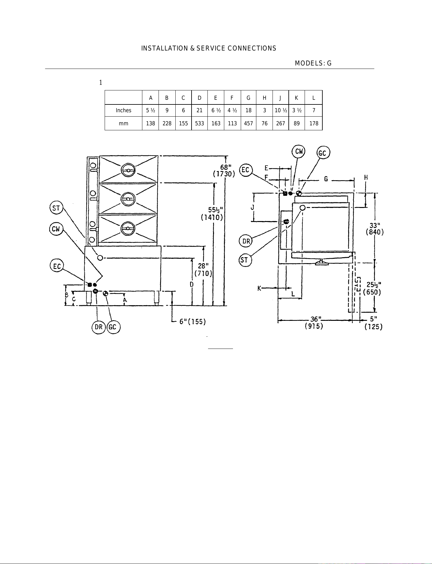
INSTALLATION & SERVICE CONNECTIONS
SECTION 1: MODELS: GC-2 & GC-3
FIG. 1
Inches 5 ½ 9 6 21 6 ½ 4 ½ 18 3 10 ½ 3 ½ 7
mm 138 228 155 533 163 113 457 76 267 89 178
A B C D E F G H J K L
LEGEND
GC Supply gas through 3/4" pipe with pressure of approx. 7" W.C. For propane use IT'
W.C. pressure. A gas shut off valve must be installed in supply piping convenient
and adjacent to appliance.
EC Unless otherwise specified. Field Wire Electrical Connection to be 120 Volts, 60
Hertz single phase with grounding wire.
DR Appliance drain is 2" pipe size. Provide open air gap type drain.
CW Cold Water supply to Boiler. Provide 3/8" copper tube. A Backflow Prevention Device
acceptable to BOCA Code or equivalent must be installed in this line.
ST Steam take-off locations to supply steam to adjacent units if desired.
2
Page 5
INSTALLATION
&
SERVICE CONNECTIONS
SECTION 1: MODELS: GC-2 & GC-3
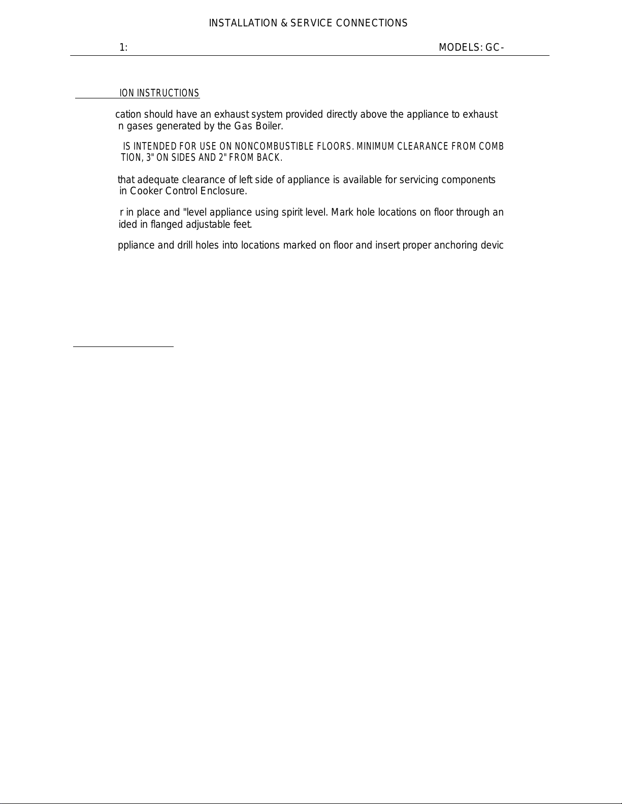
INSTALLATION INSTRUCTIONS
Cooker location should have an exhaust system provided directly above the appliance to exhaust
combustion gases generated by the Gas Boiler.
APPLIANCE IS INTENDED FOR USE ON NONCOMBUSTIBLE FLOORS. MINIMUM CLEARANCE FROM COMBUSTIBLE
CONSTRUCTION, 3" ON SIDES AND 2" FROM BACK.
Ascertain that adequate clearance of left side of appliance is available for servicing components
contained in Cooker Control Enclosure.
Set Cooker in place and "level appliance using spirit level. Mark hole locations on floor through anchoring
holes provided in flanged adjustable feet.
Remove appliance and drill holes into locations marked on floor and insert proper anchoring devices. Set
Cooker back in proper position.
Re-level the appliance, leveling the unit left to right and front to back. Appliance should be elevated on
the right 1/16" to 1/8" to assure proper compartment drainage.
Bolt and anchor appliance securely to the floor. Seal bolts and flanged feet with Silastic or equivalent
compound.
SERVICE CONNECTIONS
Make service connections as indicated in LEGEND (Fig. 1).
GAS INSTALLATION TO CONFORM TO LOCAL CODES OR IN THE ABSENCE OF LOCAL CODES TO NATIONAL FUEL
GAS CODE - ANSI Z223.1 - 1980. FURTHER NOTE THAT:
1. THE APPLIANCE AND ITS INDIVIDUAL- SHUTOFF VALVE MUST BE DISCONNECTED FROM THE GAS SUPPLY
PIPING SYSTEM DURING ANY PRESSURE TESTING OF THAT SYSTEM AT TEST PRESSURES IN EXCESS OF 1/2 PSIG
(3.45kPa).
2. THE APPLIANCE MUST BE ISOLATED FROM THE GAS SUPPLY PIPING SYSTEM BY CLOSING ITS INDIVIDUAL
MANUAL SHUTOFF VALVE DURING ANY PRESSURE TESTING OF THE GAS SUPPLY PIPING SYSTEM AT TEST
PRESSURES EQUAL TO OR LESS THAT 1/2 PSIG (3.45kPa).
ELECTRICAL GROUNDING MUST BE PROVIDED IN ACCORDANCE WITH LOCAL CODES, OR IN THE ABSENCE OF
LOCAL CODES, WITH THE NATIONAL ELECTRIC CODE, ANS1/NFPA 70 - 1981.
3
Page 6
INSTALLATION & SERVICE CONNECTIONS
SECTION 1: MODELS: GC-2 & GC-3
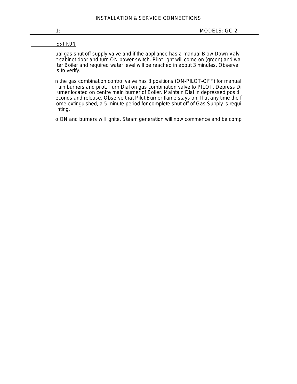
START UP TEST RUN
Open manual gas shut off supply valve and if the appliance has a manual Blow Down Valve, close
it. Open left cabinet door and turn ON power switch. Pilot light will come on (green) and water will
begin to enter Boiler and required water level will be reached in about 3 minutes. Observe water
gauge glass to verify.
The Dial on the gas combination control valve has 3 positions (ON-PILOT-OFF) for manual gas
control of main burners and pilot. Turn Dial on gas combination valve to PILOT. Depress Dial and
light Pilot Burner located on centre main burner of Boiler. Maintain Dial in depressed position for
about 30 seconds and release. Observe that Pilot Burner flame stays on. If at any time the flame
should become extinguished, a 5 minute period for complete shut off of Gas Supply is required
before relighting.
Turn Dial to ON and burners will ignite. Steam generation will now commence and be completed in
about 15 minutes. Observe that Boiler Pressure Gauge indicates steam pressure in range of 9 - 12
psi. The Pressure Gauge on the face of the Cooker Control Panel should indicate pressure of 5 to 6
psi.
Open Cooker compartment door. Dial Timer to 5 minutes and pull out Operating Handle and
observe that steam enters compartment.
With Operating Handle pulled out, dial Timer back to "O". The buzzer will now be audible and must
be silenced by releasing Operating handle. Check each compartment in a similar manner.
Close compartment door and turn Handwheel clockwise sufficiently to provide a good seal on door
gasket. Dial Timer to 5 minutes. Pull out Operating Handle and set in position. Steam entry into
compartment will be audible and Compartment Vent, located at rear left side of Cooker
compartment, will exhaust air (hissing noise) trapped in the compartment until replaced by steam.
Observe that door gasket seals properly and no leaks are evident.
After 5 minutes the Timer will read "0", Buzzer will come on, steam will cease to enter
compartment and drain valve will open to exhaust steam and condensate from compartment.
Release Operating Handle to silence Buzzer.
Observe Appliance Drain that live steam from compartment is being cooled by cold water from Cold
Water Solenoid Valve (thermostatically controlled). Turn Handwheel fully counter-clockwise to
avoid pressure on door gasket when not in use. Check each compartment in a similar manner.
During simulation of the cooking cycle, the Burners will cycle on and off to maintain steam
pressure in Boiler between 9 to 12 psi range.
Turn OFF power switch. Observe that Burners go off and if the appliance is equipped with
Automatic Blow Down Solenoid Valve, the Boiler contents water and steam, will be blown out and
exhausted through the appliance Drain. The Cold Water Solenoid Valve will now be activated as
well. If the appliance is equipped with a manual Blow Down Valve, open it.
4
Page 7
INSTALLATION & SERVICE CONNECTIONS
SECTION 2: MODELS: GC-2 & GC-3
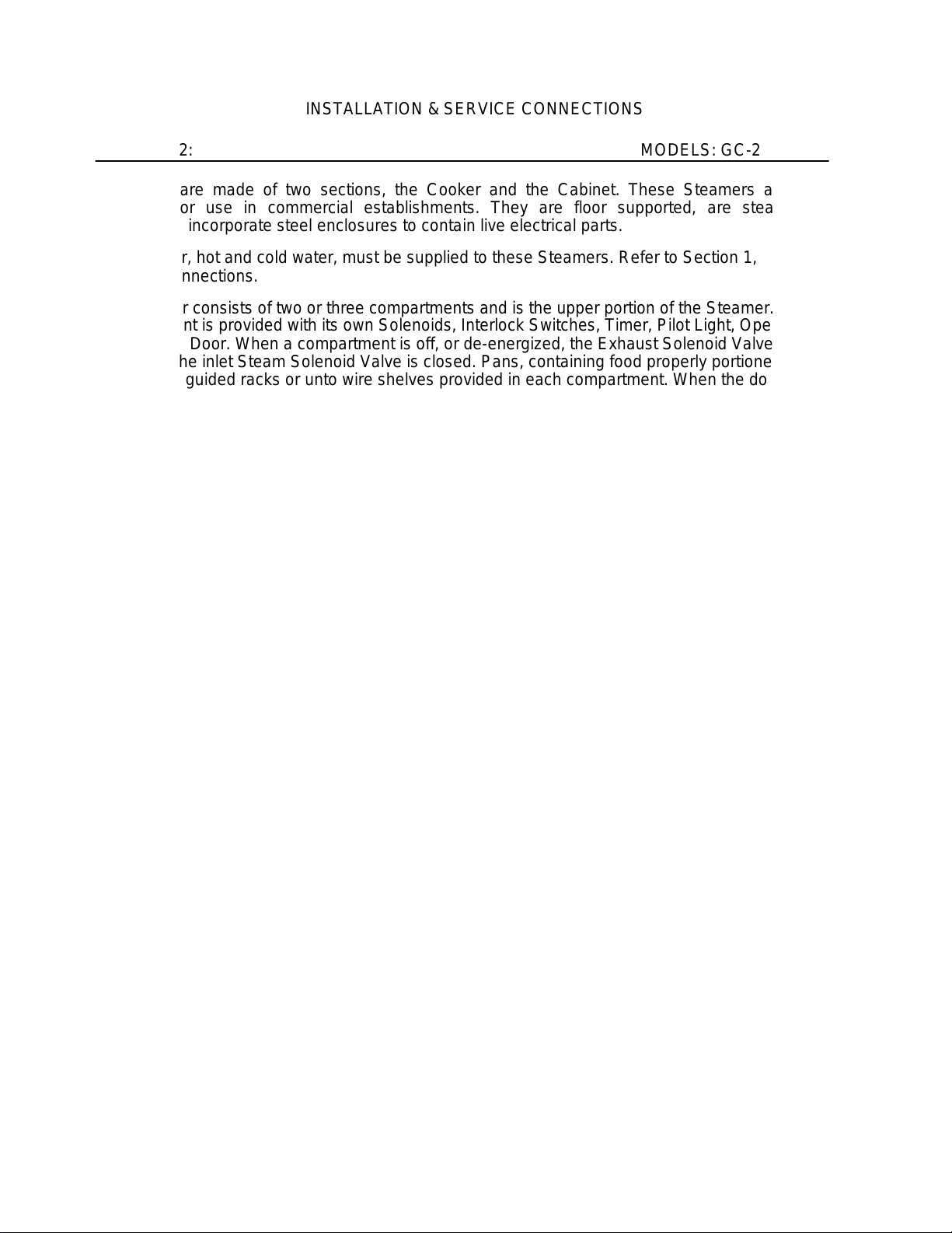
Steamers are made of two sections, the Cooker and the Cabinet. These Steamers are
intended for use in commercial establishments. They are floor supported, are steam
heated and incorporate steel enclosures to contain live electrical parts.
Gas, Power, hot and cold water, must be supplied to these Steamers. Refer to Section 1,
Service Connections.
The Cooker consists of two or three compartments and is the upper portion of the Steamer. Each
compartment is provided with its own Solenoids, Interlock Switches, Timer, Pilot Light, Operating
Handle and Door. When a compartment is off, or de-energized, the Exhaust Solenoid Valve is
open and the inlet Steam Solenoid Valve is closed. Pans, containing food properly portioned, are
placed into guided racks or unto wire shelves provided in each compartment. When the door is
closed, the Timer dialed and the Operating Handle is pulled out to the locked position, (which also
locks the door and engages the Interlock Switches), the valves are energized. Steam reduced to
maximum 6 psi pressure by the Pressure Regulating Valve will then be permitted to enter the
compartment but not exit. Air, captured in the sealed compartment is allowed to exhaust through
the Compartment Vent which will close at approximately 180°F, whence the compartment becomes
an entirely sealed chamber. The duration of the cooking cycle is controlled by the Timer and when
desired time has elapsed. Timer will read '0' and will set off an audible Buzzer and de-energize
valves. Buzzer must be silenced by releasing the Operating Handle and presumably door opened
to remove cooked food. -
The Cabinet is the lower portion of the Steamer and contains components which control the
functioning of the Gas Boiler. A switch located on the front face of the Generator Control Box, when
turned ON will provide power for the appliance and also initiate the Gas Burners to maintain steam
generation in the boiler which in turn supplies steam to the compartment.
The Gas Boiler is designed to ASME Code and approved as a steam heating boiler restricted
to operate at pressures not to exceed 15 psi and the burner system is UL tested and Certified.
Refer to Periodic Maintenance, Section 4, for detailed version of components and controls.
5
Page 8
PAN SELECTION & TIME SCHEDULES
SECTION 3: MODELS: GC-2 & GC-3
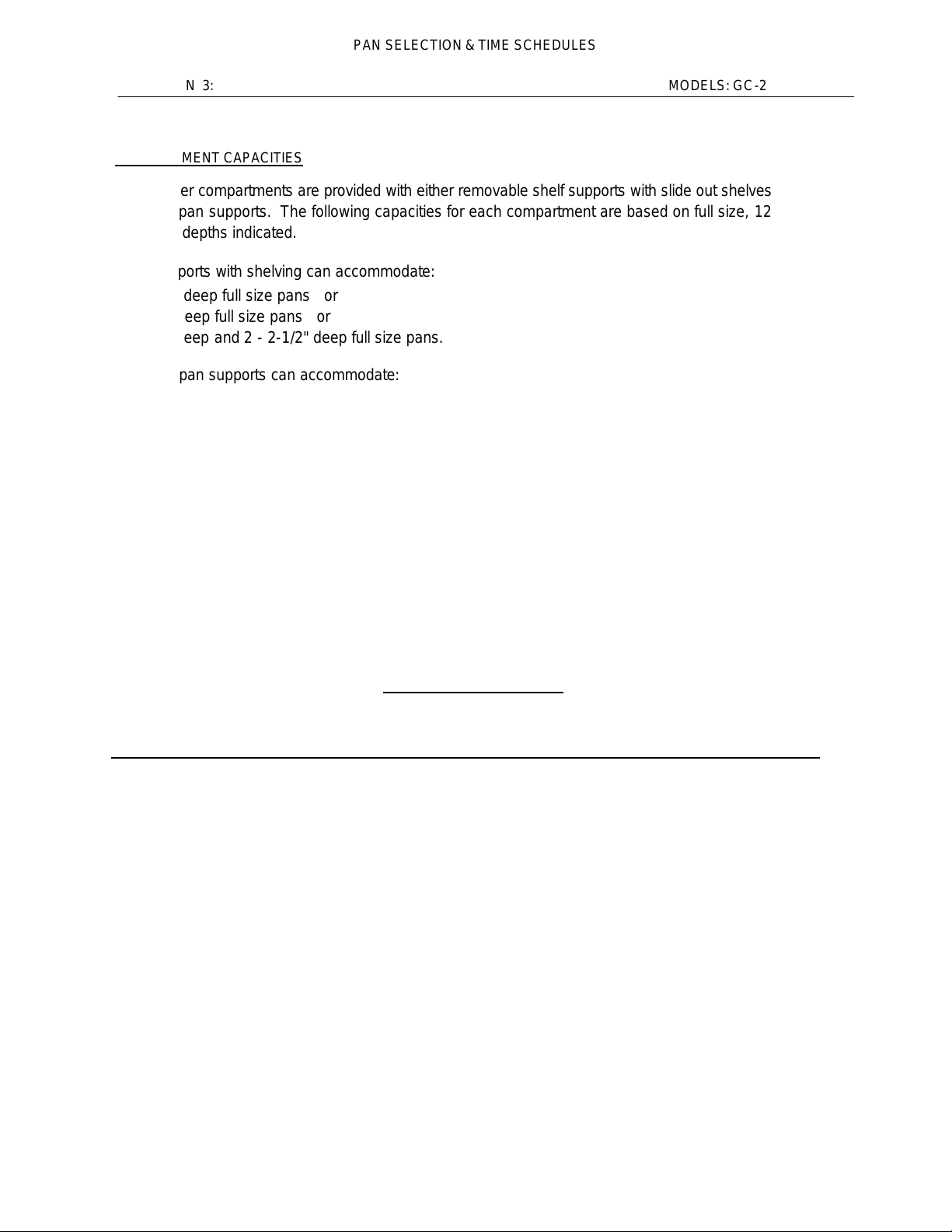
COMPARTMENT CAPACITIES
The Cooker compartments are provided with either removable shelf supports with slide out shelves OR
universal pan supports. The following capacities for each compartment are based on full size, 12" x 20",
pans and depths indicated.
Shelf supports with shelving can accommodate:
6 - 2-1/2" deep full size pans or
4 - 4" deep full size pans or
2 - 6" deep and 2 - 2-1/2" deep full size pans.
Universal pan supports can accommodate:
8 - 2-1/2" deep full size pans or
4 - 4" deep full size pans or
2 - 6" deep and 2 - 2-1/2" deep full size pans.
Food placed in pans must, where possible, be evenly spread out and not protrude above pans since
steam circulation between pans in the compartment will be impeded.
Always preheat compartments for satisfactory results.
When a11 compartments are to be used at the same time, allow one compartment to recover steam
pressure (approx. 4-1/2 p.s.i.) before commencing cooking operation on next compartment.
When time does not allow for defrosting of frozen vegetables such as loose pack peas. corn, diced
carrots, etc., they may be cooked at once provided half suggested portions in Cooking Chart are used.
COOKING CHART
ITEM PAN DEPTH
(FULL SIZE) IN MINUTES PER PAN OF PANS
TIMER SETTING
WEIGHT LBS NUMBER
Beans 2-1/2" 10 - 12 5 1 - 3
Lima & Reg. Perforated 13 - 15
4-6
Beans 2-1/2" 15-20 6 1 - 3
Waxed Perforated 20 - 25
4-6
Broccoli 2-1/2" 8-10 6 1 - 3
Waxed Perforated 10 - 12
4-6
Broccoli 2-1/2" 10 - 15 6 1 - 3
1/2" - 3/4" Perforated 15-20 4-6
Stalks
Canned 2-1/2" 4-5 7 1 - 3
Vegetables Solid 5-8
4-6
6
Page 9
PAN SELECTION & TIME SCHEDULES
SECTION 3: MODELS: GC-2 & GC-3
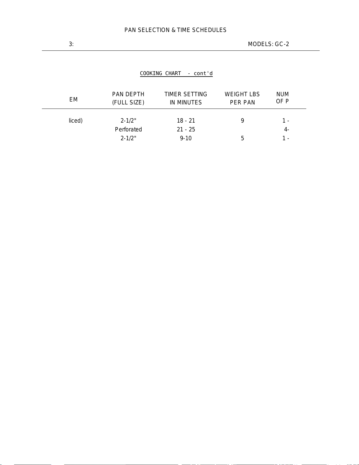
COOKING CHART - cont'd
ITEM
(FULL SIZE)
PAN DEPTH
TIMER SETTING
IN MINUTES
WEIGHT LBS
PER PAN
NUMBER
OF PANS
Carrots (sliced) 2-1/2" 18 - 21 9 1 - 3
Perforated 21 - 25
4-6
Corn 2-1/2" 9-10 5 1 - 3
Perforated 11 - 13
4-6
Chicken 2-1/2" 18 - 25 8 1 - 3
Blanched-Cut Perforated 25 - 30
4-6
Eggs - out of 2-1/2" 6-7 4 dozen 1 - 3
Shell Solid 7-8
4-6
Eggs - in 2-1/2" 2-3 3 dozen 1 - 3
Shell Perforated 4-6
4-6
Fish-Fillets 2-1/2" 8-12 3 1 - 3
Perforated 10 - 15
4-6
Meatloaf 2-1/2" 35 - 40 15 1 - 3
Solid for Broth 40 - 45
4-6
Peas 2-1/2" 6-7 5 1 - 3
Perforated 8-9
4-6
Potatoes cut 2-1/2" 20 - 25 10 1 - 3
Regular Perforated 25 - 30
4-6
Potatoes cut 2-1/2" 15 - 18 10 1 - 3
French Fry Perforated 18 - 20
4-6
Spinach 4" 3-5 3 1 - 2
cut, cleaned Perforated 4-6
3-4
Rice 4" 22 - 24 4 1 - 2
1 Gallon Water Solid -,25-27
3-4
Spaghetti 4" 20 - 22 3 1 - 2
1-3/4 Gal. Water Solid 23 - 26
3-3
Turkey 2-1/2" 50 - 60 10 - 12 1 - 3
Perforated 60 - 75
4-6
7
Page 10
PERIODIC MAINTENANCE
SECTION 4: MODELS: GC-2 & GC-3
FIG. 2
SIDE VIEW
8
Page 11
PERIODIC MAINTENANCE
SECTION 4: MODELS: GC-2 & GC-3
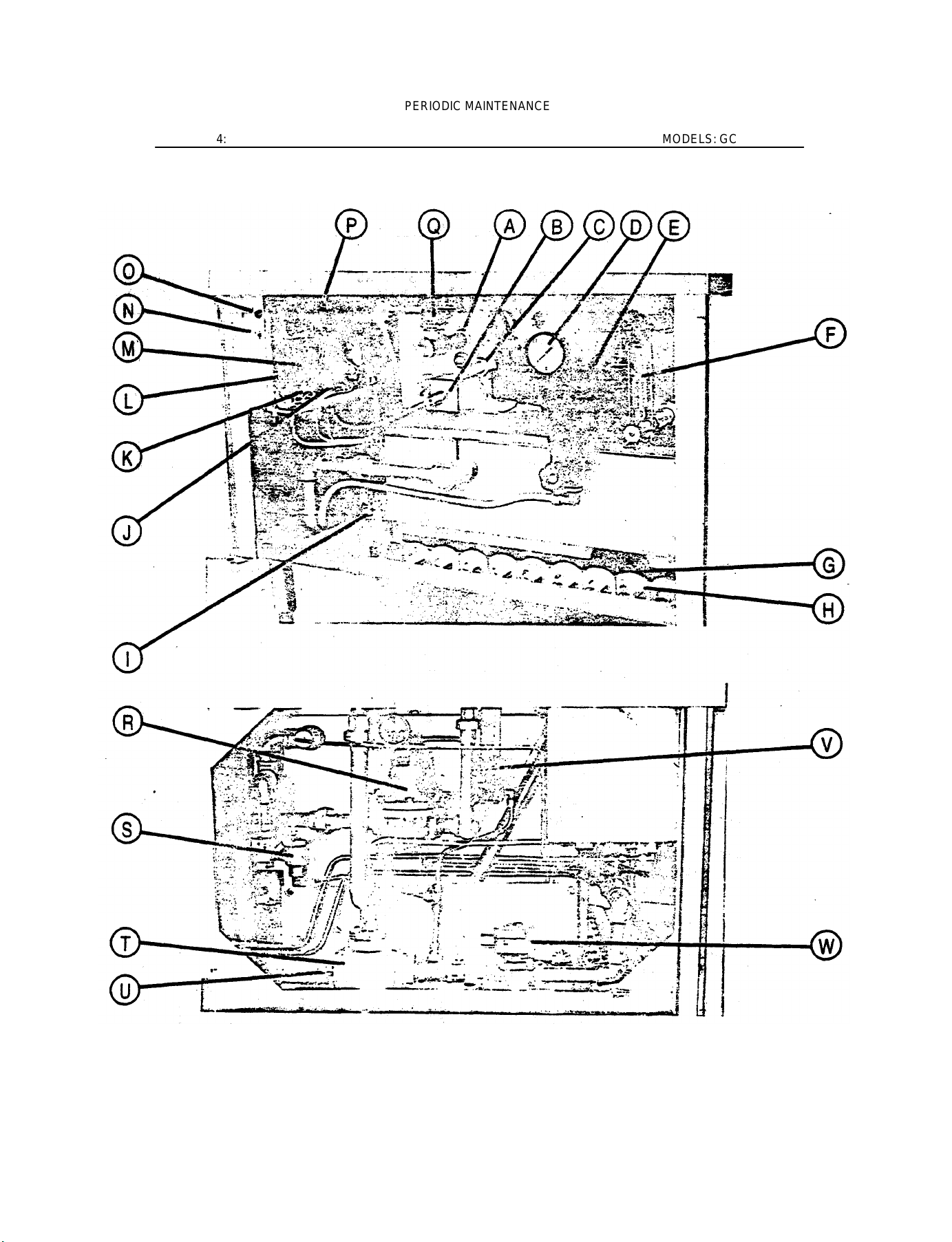
Fig. 2: The Cabinet is the lower section of the Steamer providing not only a base for the Cooker to be positioned at a
proper working height but also the enclosure for the Gas Boiler and Controls.
THE APPLIANCE AREA MUST BE KEPT FREE AND CLEAR FROM
COMBUSTIBLES. DO NOT OBSTRUCT THE FLOW OF COMBUSTION AND
VENTILATION AIR.
FRONT VIEW
Item A: Gas Boiler weldment assembly.
Item B: Safety Sensor, enclosed by the Sensor Cover Box, is a Boiler protective device which will shut off the Main
Burners when excessive heat occurs should the water level in the Boiler drop below a level sufficient to immerse and
protect the Boiler tubes, heads and shell that come in contact with direct heat from the Burners.
Item C: Handhole Cover Assembly when unbolted and removed allows internal examination and cleaning of Boiler if
required.
AT LEAST TWICE A YEAR REMOVE HANDHOLE COVER ASSEMBLY.
INSPECT BOILER INTERIOR FOR SCALANT AND LIME BUILD UP.
Item D: The Pressure Gauge is directly above and threaded to the Water Level Control. It should read '0' during shut
down and function in a range of approximately 9 to 13 p.s.i. during operation of the appliance.
Item E: The Water Level Control is a mechanical switch intended to maintain proper water level in the Boiler. A Float is
contained within the chamber of the Water Level Control and when it drops, it will trip the switch in the control and
demand sufficient water to replenish it to the proper level.
A MANUAL VALVE LOCATED DIRECTLY BELOW THE WATER LEVEL
CONTROL CHAMBER MUST BE OPENED BRIEFLY AT LEAST ONCE A WEEK
TO BLOWDOWN SEDIMENT AND SCALANT THAT MAY BE LODGED IN THE
CHAMBER. FAILURE TO DO SO MAY CAUSE EXCESSIVE
ACCUMULATION, SEIZURE OF THE FLOAT AND EVENTUAL MALFUNCTION
OF THE WATER LEVEL CONTROL.
Item F: The Water Gauge assembly has a glass tube for visual verification that water level is being maintained in the
Boiler during operation. The manual valves at the top and the bottom of this assembly must be fully open and only
closed if damage should occur to the glass tube.
OBSERVE THAT THE WATER IS CLEAN AND CLEAR IN THE GLASS TUBE.
THE APPEARANCE OF EXTREME MURKINESS IN THE WATER
INDICATES INADEQUATE WATER QUALITY AND WILL CAUSE FAILURE
OF CONTROLS AND THE APPLIANCE. WARRANTY DOES NOT COVER
MALFUNCTION DUE TO POOR WATER CONDITIONS.
9
Page 12
PERIODIC MAINTENANCE
SECTION 4: MODELS: GC-2 & GC-3
Item G: Pilot Burner should remain lit at all times unless appliance will not be in use for an
extended period of time.
IF AT ANY TIKE THE FLAME SHOULD BECOME
EXTINGUISHED. A 5 MINUTE PERIOD FOR COMPLETE SHUT
OFF OF GAS SUPPLY IS REQUIRED BEFORE RELIGHTING.
Item H: Main Burners of aluminized steel tube.
FLOOR AREA BENEATH BURNERS MUST BE KEPT FREE AND
CLEAR TO PROVIDE AIR FOR COMBUSTION AND
VENTILATION.
Item I: Gas Combination Control Valve regulates flow of natural gas (or propane) to Burners.
Operation is dependent on other controls. Refer to START UP TEST RUN - SECTION 1.
Item J: Cold Water Solenoid Valve fastened to the right rear bottom of Generator Control Box
supplies cold water to condense live steam before it exhausts into the drain and is controlled by the
Thermostat (Item P).
Item K: Hot Water Solenoid Valve fastened to the bottom of Generator Control Box immediately in
Front of Item J feeds hot water to the Boiler but its functioning is entirely dependent on the Water
Level Control (Item E).
Item L: Operating Pressure Switch fastened to the inside bottom front of the Generator Control
Box is plumbed to sense the pressure in the Boiler and thence control the operating cycle of the
Gas Combination Control Valve (Item I). This switch is factory set to energize the Gas Combination
Control Valve and ignite the Main Burners at 9 psi but to de-energize the Valve and turn off
Burners at 11 ½ psi thus maintaining a pressure range in the Boiler between 9 psi to
approximately 13 psi (override considered).
Item M: Override Pressure Switch similar to and located directly behind the above switch senses
steam pressure in excess of the normal operating range which occurs only at initial Start-Up of the
Boiler at approximately 13 psi and thence energizes Solenoid Valve (Item V) to open briefly to
allow for discharge of said excess pressurized steam thence the Boiler becomes stabilized.
Item N: Power Switch fastened to the front fact of the Generator Control Box when switched ON
will automatically begin the steam generating process in the Boiler.
Item O: Pilot Light is located directly above the Power Switch and when lit (green) indicates power
is ON.
Item P: A Thermostat mounted on the back wait of the Generator Control Box has its heat
sensing capillary bulb fastened to the appliance Drain. When excessive heat (i.e. steam) comes in
contact with the bulb, the Thermostat will energize the Cold Water Solenoid Valve (Item J).
10
Page 13
PERIODIC MAINTENANCE
SECTION 4: MODELS: GC-2 & GC-3
Item Q: Safety Valve is a protective device set at 15 psi. Malfunction or improper setting of controls may allow the
pressure to exceed 15 psi in the Boiler and will consequently set off this valve.
ONCE A WEEK THIS VALVE SHOULD BE TRIPPED DURING OPERATION TO
ASSURE THAT IT FUNCTIONS PROPERLY.
LEFT SIDE VIEW
Item R: Pressure Regulator reduces the pressure of the steam supplied from the Boiler to the Steam Header and the
Cooker compartments.
TWICE A YEAR UNSCREW THE LARGE HEX HEAD PLUG LOCATED AT THE
BOTTOM OF THE REGULATOR AND REMOVE AND CLEAN THE STRAINER.
Item S: A Thermostatic Steam Trap is plumbed to the steam supply piping from the Boiler and is a mechanical device
that closes on high temperatures and opens when the temperature drops. This Trap allows water formed from
condensed steam to exhaust into the appliance Drain but will retain steam being of a higher temperature.
Item T: Drain for compartments and Boiler approximately 2" pipe size. Must be provided with open air gap type floor
drain.
Item U: Thermostat Capillary Bulb fastened to appliance Drain. Refer to Item P.
Item V: Override Solenoid Valve functions only briefly at initial Start-Up of Boiler and is controlled by override Pressure
Switch (Item M).
Item W: Boiler Blowdown Valve is plumbed to the drain pipe of the Boiler and when specified as automatic will be a
solenoid (electrically operated) valve which will close when energized in order to facilitate maintenance of proper water
level in the Boiler.
HOWEVER. THE STEAMER SHOULD BE SWITCHED OFF AT LEAST ONCE
DAILY WHICH WILL DE-ENERGIZE AND OPEN THE VALVE IN ORDER FOR
THE BLOKDOWN PROCEDURE TO OCCUR AND REMOVE SEDIMENTS.
SCALANTS AND LIME BUILD-UP IN THE BOILER. IF THE APPLIANCE IS
SUPPLIED WITH A MANUAL VALVE. IT SHOULD BE OPENED DAILY WHEN
THE APPLIANCE IS SHUT DOWN.
11
Page 14
PERIODIC MAINTENANCE
SECTION 4: MODELS: 6C-2 &GC-3
FIG. 3
STEAM
EXHAUST
IN
TO DRAIN
12
Page 15

PERIODIC MAINTENANCE
SECTION 4: MODELS: GC-2 & GC-3
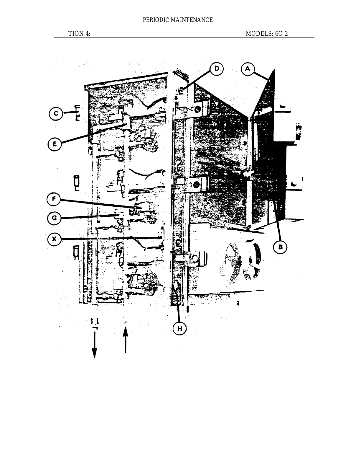
Fig. 3: The Cooker is the upper section of the steamer and is either a two or three compartment
appliance. Each compartment functions independently with its own controls and 1s a separated sealed
steam chamber during the cooking operation.
DO NOT OBSTRUCT THE FLOW OF COMBUSTION GASES
THROUGH FLUE STACK LOCATED DIRECTLY BEHIND AND ABOVE
COOKER.
Item A: A Door Gasket is provided on each compartment door and ensures proper sealing of the
cooking compartment.
WASH THE GASKET SEALING SURFACE WITH MILD DETERGENT DAILY
TO REMOVE HARMFUL FOOD ACIDS. TURN HANDWHEEL COUNTER-
CLOCKWISE TO RETRACT GASKET PLATE FULLY INTO DOOR WHEN NOT
IN USE. DAMAGE TO GASKET SEALING SURFACE, SUCH AS NICKS OR
CUTS WILL CAUSE STEAM LEAKAGE.
Item B: A Thrust Screw is located inside the door and its shaft protrudes through the door centre and is
fastened directly to the Handwheel. Any force on the Handwheel is transmitted through the Thrust
Screw simultaneously against the Gasket Retaining Plate and Door Gasket to seal the compartment.
THE THRUST SCREW OF EACH COMPARTMENT DOOR SHOULD BE
LUBRICATED ONCE A MONTH. TO GAIN ACCESS TO SCREW, OPEN
COMPARTMENT DOOR AND TURN HANDWHEEL CLOCKWISE (CLOSE
DIRECTION) UNTIL GASKET RETAINING PLATE IS FULLY EXTENDED
OUT OF DOOR. GRASP FINGER HOOKS AND LIFT UP AND OUT TO
REMOVE GASKET PLATE ASSEMBLY. APPLY GREASE NLG12
CONSISTENCY OF 285W60 VISCOSITY LIBERALLY TO THRUST
SCREW ROTATING HANDWHEEL TO ASSURE COMPLETE COVERAGE.
REPLACE GASKET PLATE AND TURN HANDWHEEL COUNTERCLOCKWISE RETRACTING GASKET PLATE INTO DOOR. CLOSE DOOR.
Item C: A Compartment Vent is plumbed to each compartment directly behind the Cooker Control
Enclosure. During preheat or initially at commencement of cooking operation it remains open to
exhaust air and condensate from the compartment. It will close at approximately 180°F.
Item D: A Timer is fastened to the Cooker Control Panel for each compartment and can be dialed from
0 to 60 minutes. At completion of the cooking cycle, dial should read '0' and an audible Buzzer will
commence and can only be silenced by releasing the Operating Handle-Item E: A Pressure Relief
Valve is located inside the Control Enclosure and is plumbed to the top of the Steam Header. This
protective device will open when 8 p.s.i. steam pressure is exceeded. Replace if leakage occurs or it
opens below rated pressure.
13
Page 16

PERIODIC MAINTENANCE
SECTION 4: MODELS: GC-2 & GC-3
Item F: A Steam Solenoid Valve is provided for each compartment and will open when energized to
allow steam entry into the compartment. This valve will remain de-energized and closed if the Timer
reads '0' and/or the Operating Handle is in the released position.
Item G: An Exhaust Solenoid valve is provided for each compartment and operates in reverse to Item
F; that is, it will close when energized thus seating the steam, provided by the Steam Valve, within
the compartment.
ANY FOREIGN MATERIAL, OTHER THAN STEAM OR WATER, SHOULD
NOT BE ALLOWED TO EXHAUST THROUGH THIS VALVE. AFTER
OPERATION WIPE AND REMOVE FOOD OR ANY OTHER PARTICLES
FROM EACH COMPARTMENT BOTTOM.
A stainless steel strainer is provided in each compartment just ahead of the exhaust port as a
protective device for this valve. Remove, clean and replace if excessive food and/or dirt accumulation
is evident.
IF PARTICULARLY GREASY FOODS HAVE BEEN COOKED IN THE
COMPARTMENT, DEPOSITS MAY ACCUMULATE IN EXHAUST VALVES AND
MUST BE REMOVED BY CLOSING DOOR, SEALING COMPARTMENT, SETTING
TIMER AND AT FREQUENT INTERVALS PULL OUT AND RELEASE OPERATING
HANDLE TO BLOW STEAM THROUGH VALVE AND DISSOLVE GREASE.
Item H: A Pressure Gauge is fastened to the bottom face of the Cooker Control Panel. It is plumbed to sense
pressure in the Steam Header. When compartments are inactive, it should read approximately 6 p.s.i. but will
fluctuate between 4^5 to 6 p.s.i. during the cooking cycle. Pressure above 6 p.s.i. indicates that Pressure
Regulating Valve is set too high and may set off Pressure Relief Valve (Item E).
Item I: Flue Stack Assembly is located directly behind Cooker (See Page 29, Parts No. 7 & 8) and provides
for exhaust of combustion gases.
AT LEAST TWICE A YEAR EXAMINE THAT INTERIOR OF FLUE STACK IS
CLEAN. IF ACCUMULATION OF DIRT AND/OR SOOT IS APPARENT, THE
STACK COVER AND FLUE STACK MUST BE REMOVED AND CLEANED. ALSO
PORTION OF FLUE EXTENDING BELOW CABINET SURFACE TO BOILER MUST
BE CLEANED.
14
Page 17

OPERATING INSTRUCT IONS
SECTION 5: MODELS: GC-2 & GC-3
STEAM GENERATING PROCESS
Open left door of cabinet and turn ON power switch on face of Generator Control Box. Pilot light win
come on (green), burners will ignite and steam generating process will begin. After approximately 20
minutes, sufficient amount of pressurized steam will have been generated in the Boiler and the Cooker
is now ready for the Cooking Operation.
COOKING OPERATION
-If the appliance has been standing idle for a considerable length of time, the compartments will be cold
and must be pre-heated before commencing the Cooking Operation.
-Refer to Pan Selection and Time Schedules in Section 4.
-Turn Handwheel clockwise sufficiently to provide a good seal on gasket.
-Set Timer to desired cooking cycle.
-Pull out Operating Handle and set in position.
-Pilot light will indicate that cooking cycle is now in progress.
-Completion of the cooking cycle is indicated by the buzzer going on and the pilot light off.
-Set Operating Handle back and turn Handwheel fully counter-clockwise.
-Open door and remove food in pans.
CLEANING
At the end of each day turn appliance OFF. Remove pans and side racks from compartments. Remove
food sediment from compartment bottoms and wash compartment interior with mild detergent and rinse.
Never use steel wool on stainless steel equipment. Replace washed racks and shelves. Wash the
gasket sealing surface of compartment door daily with mild detergent to remove harmful food acids.
Turn Handwheel fully counter-clockwise to retract gasket plate into door to avoid pressure on gasket
when not in use.
CONTACT THE FACTORY, THE FACTORY REPRESENTATIVE OR A LOCAL
SERVICE COMPANY TO PERFORM MAINTENANCE AND REPAIRS SHOULD
THE APPLIANCE MALFUNCTION. REFER TO WARRANTY TERMS.
15
Page 18

SERVICE INFORMATION
SECTION 6: MODELS: GC-2 & GC-3
COMPARTMENT DOORS
Door Hasp does not engage Door Catch property
Check if door appears loose at hinges since worn out Bronze Bushings will cause misalignment of door
and bushings must be replaced. Force out Tension Pins in Hinges with pin punch. (Refer to Parts List
Section 7 - Compartment Door Assembly). Eject Hinge Pins and remove door. Force out worn Bronze
Bushings and replace with care since this is a snug fit.
However, if door is rigid at hinges, then Door Hasp may require adjustment. Remove Cooker
Enclosure Panel. Remove Hasp Pin and either add or delete washer under Hasp for proper height.
Handwheel is binding or difficult to turn
Foreign matter or lack of lubricant on dry Thrust Screw may cause threads to bind. Refer to Section 4,
Periodic Maintenance.
If Thrust Screw is bent or threads are badly worn, remove Thrust Screw and replace. Refer to Steamer
Compartment Door Assembly, Section 7, Page 23.
Door Gasket is leaking
Gasket Retainer Cap Screws may be loose and must be tightened to prevent steam leakage.
Gasket may be nicked, cut or at end of useful life and must be replaced.
Door may hang loosely and Gasket edges do not align with compartment surface properly. Correct
as previously noted.
The Door Gasket and Aluminum Plate assembly may be hanging improperly within door on supporting
Alignment Screws. Remove Gasket Plate Assembly and adjust Alignment Screws slightly.
As previously noted, Handwheel may be difficult to turn and excessive friction prevents exerting
pressure required for sealing.
16
Page 19

SERVICE INFORMATION
SECTION 6: MODELS: GC-2 & GC-3
COOKER PROBLEMS
Water accumulates in bottom of compartment
Water accumulation in bottom of compartment is primarily condensed steam and failure to drain out
completely may be due to improperly leveled appliance. Refer to Section 1, Installation Instructions.
Stainless steel compartment Screen protecting exhaust port in compartment may be clogged with debris
and screen must be removed, cleaned and replaced. Exhaust Solenoid Valve may be obstructed with
accumulated grease which will impede drainage of water. Refer to Section 4, Periodic Maintenance.
If grease is not the obstruction, then with power Off, the Exhaust Header must be disconnected at all
unions and removed. The Union Elbow must be unthreaded from the Exhaust Solenoid Valve. Visually
inspect the Exhaust Header and the valve for obstruction. Verify that no obstruction is present by
passing an object, such as a pencil, freely through valve and also examine that exhaust port (stainless
steel 1/2" fitting welded to Cooker body) is internally clean. Reconnect alt plumbing.
However, the Exhaust Solenoid Valve may be incapable of opening. Since this valve contains a
moveable blade and when de-energized, the blade reacts as a guillotine which should be free to move
fully down into the valve pocket (projection at bottom of valve) so that the pierced hole in the blade aligns
perfectly with the body opening. If debris has accumulated in the bottom of the valve pocket, then blade
obviously will be impeded from moving into pocket completely. Further, a burnt out valve coil is likely.
With valve removed from Cooker body, remove retaining clip at top of solenoid. Grasp (green) cover
and housing intact with coil inside and slide off from valve. Unscrew projecting tube from top of valve
body and remove internal mechanism together with blade assembly. Next unscrew both assembly bolts
and split brass body of valve removing loose internal parts. Now flush and clean pocket thoroughly.
Reassemble all parts in reverse order of disassembly. Energize valve with 120 V power to verify that
valve is functional. As mentioned, coil may require replacement. Reconnect all plumbing.
Compartment remains pressurized at end of cooking cycle
As noted, when water accumulates at bottom of compartment, an obstructed Exhaust Solenoid Valve
must be cleansed to allow not only water but also pressurized steam to exhaust at end of cooking cycle.
17
Page 20

SERVICE INFORMATION
SECTION 6: MODELS: GC-2 &
GC-3
COOKER PROBLEMS (cont'd)
Steam escapes from compartment during cooking cycle
Initially in the cooking cycle, air is displaced by steam in the compartment through the
Compartment Vent (Thermostatic Trap). Displacement of air is audible by the hissing noise but
should cease when the Thermo-static Trap reacts to the higher temperature of steam entering
the trap. However, malfunction will occur if dirt is lodged internally in metal to metal seat of trap.
Unscrew bonnet from top of Compartment Vent. Remove internal mechanism, cleanse
thoroughly and replace. If malfunction persist, replace Compartment Vent.
As mentioned previously, if the Exhaust Solenoid Valve has a burnt out coil, it will be
incapable of being energized and thus remain open allowing steam to exhaust.
Cooking cycle cannot be activated
Although this appliance has been thoroughly tested, it is advisable to inspect that all wire
terminations are positive and secure before assuming any other malfunction.
When Power Switch in Generator Control Box of Cabinet is ON and steam pressure reading
shows 5 to 6 p.s.i. on Pressure Gauge of Cooker Control Panel and all compartments fail to
function for the cooking cycle, then power obviously is not being supplied to Cooker and wiring
must be checked.
The magnetic coil of the Steam Solenoid Valve may be defective and require replacement. With
Compartment Door open, observe if steam enters compartment when an outside source of (120
V) power is supplied to valve leads. If the valve energizes and steam enters compartment, then
valve is operative and malfunction of cooking cycle is due to either a defective Timer or
Microswitch.
When Timer is dialed. Operating Handle pulled out and cooking cycle will not activate in only
one compartment, then Microswitches may require adjustment of their activating levers or
replacement if defective. With Cooker Cover Panel removed, observe that levers of
Microswitches are fully engaged by Arm of Operating Handle as it is pulled out. Bent Levers
may fail to activate Microswitch(es) resulting in failure to energize valves and/or Timer and must
be straightened (by hand) to assure positive contact.
A defective Timer will prevent cooking cycle from functioning and must be replaced. It is not
recommended that repair of Timer be attempted.
18
Page 21

SERVICE INFORMATION
SECTION 6:
MODELS: GC-2 & GC-3
COOKER PROBLEMS (cont'd)
Water enters compartment through Steam Solenoid Valve
If the cooking cycle is on and water enters compartment through valve and steam pressure is
nonexistent, then this may indicate malfunction of the Water Level Control (in Cabinet). The
switch in the Mater Level Control may be defective and remain in the closed position,
consequently energizing the Boiler Water Supply Valve to continuously supply water to fill the
Boiler, Steam Header and eventually overflow into the compartments) through Steam
Solenoid Valve(s).
However, a more likely cause is excessive sealant and/or lime build up within the chamber of
the Water Level Control, which having formed around the float, prevents it from fluctuating
upwards with the increase in water level and thus the float is unable to trip the switch in the
control to de-energize the solenoid valve and consequently stop water from being fed to the
Boiler and flooding the system. Refer to Boiler on Removal of Sealants, etc.. This malfunction
is extremely serious and indicates that water quality is inadequate and must be rectified
immediately with a proper water conditioner.
Pressure Relief Valve leaks or opens frequently
This valve sits on top of the Steam Header and assures that pressure will not exceed 8 p.s.i..
The valve may "leak if dirt is under valve disc. Manually trip lever of valve smartly a few times
in an effort to dislodge and blow dirt away. Pressure Gauge on Cooker Control Panel should
read maximum 6 p.s.i. and if valve continues to leak, then it is defective and must be
replaced.
Pressure in Steam Header may be too high and Pressure Regulating Valve will require
adjustment. To re-adjust, loosen lock nut on the adjusting screw and turn adjusting screw
counter-clockwise to decrease pressure.
19
Page 22

SERVICE INFORMATION
SECTION 6: MODELS: GC-2 & GC-3
CABINET CONTROL PROBLEMS
Safety Relief Valve blows and releases steam frequently
The Safety Relief Valve is set at 15 p.s.1. and is a protective device intended to prevent
pressure from exceeding 15 p.s.i. in the Boiler. During the operating cycle, observe the
fluctuating pressure range as indicated on the Pressure Gauge located directly on top of the
Water Level Control. The fluctuating range should read approximately 9 to 12 p.s.i. during a
normal operating cycle and if the Safety Relief Valve blows prematurely then assume it must
be defective and requires replacement.
However, if the pressure reading, indicated on the Pressure Gauge, approaches 15 p.s.i,, then
lower adjustment of the Pressure Switches are required. Remove Cover from Generator
Control Box and locate both switches at bottom left side on Control Box. When facing Pressure
Switch in the upright position, the adjusting nut on the higher top point to the back controls the
high pressure setting of that switch and the adjusting nut on the tower top surface to the front
of the switch controls the low pressure setting of that switch. Both nuts when turned counter
clockwise with either a 1/4" wrench or slotted screwdriver will tower the pressure settings.
Refer to Periodic Maintenance Section 4, for proper pressure settings. Each nut should be
turned slightly and the pressure reading on the Gauge observed before adjusting the next nut
unnecessarily.
Water is not being supplied to Boiler
When the appliance is first turned ON, and assuming that water supply is definitely available to
the appliance, and after 20 minutes no water can be observed in the Water Gauge Assembly,
then either the Solenoid (Hot Water) Valve is defective or is incapable of being energized by
the Water Level Control. As mentioned previously, the float within the chamber of the Water
Level Control may be seized up and remain stuck in the upper position by sealant thereby
falsely indicating sufficient water is present in the Boiler. The Water Level Control Assembly
must be detached, removed and thoroughly cleansed to remove sealants and lime build up.
Refer to Boiler on Removal of Sealants etc.. This malfunction indicates extremely poor water
quality being supplied to the appliance and must be attended to immediately to avoid complete
breakdown of the appliance.
Another possibility is that as quickly as water is fed to the Boiler it is being drained through an
open Boiler Blow down Solenoid Valve which cannot close since it is not being energized either
through defective wiring or a burnt out coil.
This valve is similar in construction to the Exhaust Solenoid Valve mentioned previously and
may malfunction due to sealants lodging in the pocket of the valve. Refer to page 17 Cooker
Problems - "Water accumulation in the bottom of compartment" - for procedure of cleaning this
valve.
20
Page 23

SERVICE INFORMATION
SECTION 6: MODELS: GC-2 & GC-3
CABINET CONTROL PROBLEMS (con t' d )
Boiler Slowdown Valve does not drain
When the appliance is turned OFF, the Boiler Slowdown Valve 1s de-energized and consequently opens
and the water contained in the Boiler being under pressure, should be blown through this Valve and be
noticeably visible exhausting out the appliance Drain. However, if the blow down operation appears to
function rather sluggishly or not at all, then assume that considerable sealant may be lodged in the drain
pipe and/or the Valve. Disconnect the Valve from the drain line and inspect both the Valve and the drain
pipe fixed to the Boiler. If considerable sealant or lime build up is apparent then not only the Valve but also
the Boiler and Water Level Control must be thoroughly cleansed. Refer to Gas Boiler (below) on Removal of
Sealants etc. for procedure.
Gas Boiler achieves pressure slower than normal
If the Boiler requires considerably more time than 20 minutes to achieve normal operating pressure (9-12
p.s.i.), then assume that heavy build up of sealant has completely coated the interior of the Boiler and
consequently heat transfer is hampered by the insulating effect of the sealant. Unbolt and remove the Hand
hole Cover Plate and Gasket assembly. Examine interior of Boiler for sealant and/or lime build up.
If considerable sealant is evident then the Boiler Blow down Valve (similar to Exhaust Solenoid
Valve) must also be examined. Refer to page 17 on cleaning procedure.
Removal of sealants
Disconnect all (3) union pipe fittings and hot water tilt connection to Boiler. Cap and seal all 4 opened
connections to Boiler.
Plumbed directly to the Boiler drain pipe is a pipe Tee with a plug which must be removed and
replaced with a convenient length of pipe to provide drainage into a suitable receptacle placed in
front of the appliance.
With hose through Hand hole, flush out all loose sealants allowing them to drain through Boiler drain
pipe (into receptacle). If drain pipe is clogged with sealant and unable to drain, ream open with a
suitable tool such as screwdriver or long rod from inside of Boiler and through drain pipe Tee. With wire
brush, loosen as much sealant as possible and flush out of Boiler.
Plug drain pipe. Prepare a solution of one part Muriatic (Hydrochloric) Acid to seven parts of water and pour
into Boiler through Handhole up to Handhole opening level and allow to stand for several hours or overnight.
Unplug drain pipe and allow solution and sealants to drain out. During this procedure, exercise extreme care
to avoid personally coming in contact with acid. If contact occurs, wash acid off immediately with clean
water.
Remove all caps and reconnect all unions and connections to Boiler.
21
Page 24

SERVICE INFORMATION
SECTION 6: MODELS: GC-2 & GC-3
CABINET CONTROL PROBLEMS (cont'd)
Malfunction of Pilot Burner flame
The Pilot Burner should have a steady blue flame about 1" long which must envelop and
heat the thermocouple tip in order for the Main Burners to ignite on demand.
Check that required gas pressure is available to Gas Combination Control Valve.
Unusually strong floor drafts may interfere with pilot flame preventing it from properly
heating the thermocouple tip and result in ignition failure of Main Burners.
An inadequately heated thermocouple tip can result from an unusually short pilot flame
which most often can be attributed to insufficient or irregular gas supply to Pilot Burner.
Examine the gas supply tube (1/4" OD) that it has no severe kinks. Remove tube and check
that free flow of gas is possible through it. Also, if the orifice of the Pilot Burner is slightly
plugged, gas flow will be impeded causing an irregular flame and will require replacement.
Main Burners refuse to ignite
Assuming that the Pilot Burner flame is of proper size and envelops the thermocouple tip,
but the Main Burners refuse on demand to ignite, then possibly the Thermocouple
Assembly is malfunctioning. Examine that proper contact of thermocouple to Gas
Combination Control Valve is being maintained by checking that the nut connection at Valve
is initially finger tight with an additional 1/2 turn by wrench. If malfunction persists, replace
Thermocouple Assembly and retest.
Finally, when all above corrections have been made, assume that Gas Combination
Control Valve is defective. Replace Valve, it is not recommended that disassembly and
repair be attempted.
22
Page 25

PARTS LIST
SECTION 7: COMPARTMENT DOOR ASSEMBLY
FIG.4
23
Page 26

COMPARTMENT STEAMER
GAS BOILER
PARTS
INSTALLATION OF OTHER THAN GENUINE SOUTHBEND PARTS WILL VOID THE WARRANTY ON THIS
EQUIPMENT.
SERIAL NUMBER/RATING PLATE:
The serial plate is located inside the left door of the cabinet base on the top of the panel
Replacement parts may be ordered either through a Southbend Authorized Parts Distributor or a South-bend
Authorized Service Agency.
When ordering parts please supply the Model Number, Serial Number. Part Number. Description, plus Finish. Type
of Gas and Electrical Characteristics, as applicable.
For parts not listed consult a Southbend Authorized Parts Distributor or Southbend Authorized Service Agency. If
necessary, please consult Southbend Escan Parts Department for assistance.
WARNING:
Page 27

PARTS LIST
SECTION 7: COMPARTMENT DOOR ASSEMBLY
From Fig. 4
ITEM NO. PART NO. DESCRIPTION QUANTITY
1 1-55S4 Gasket Screw 8
2 8-1176 Finger Hook 2
3 8-1177 Gasket Panel 1
4 8-1178 Door Gasket 1
5 8-1179 Aluminum Plate 1
6 1-55S4 Support Angle Screw 3
7 8-1180 Support Angle 1
8 8-1181 Alignment Screw 2
9 1-69CO Nut 2
10 8-1182 Thrust Bar 1
11
8-1183 Thrust Screw 1
12 2-W1B6 Washer 1
13 8-1184 Compartment Door 1
14 8-1187 Bronze Bushing 2
15 1-T6S8 Tension Pin 2
16 8-1188 Hinge 2
17 8-1189 Hinge Pin 2
18 2-011R '0' Ring 6
19 1-65S4 Hinge Screw 6
20 8-1190 Aluminum Bushing 1
21 8-1191 Handwheel 1
22 2-W9S8 Hasher 1
23 8-1193 Open-Close Label 1
24 1-65S6 Handwheel Screw 1
25 1-K5U5 Thrust Screw Key 1
26 1-59CO Nut 2
27 2-57U5 Shoulder Screw 2
24
Page 28

PARTS LIST
25
SECTION 7: COOKER ASSEMBLY
FIG. 5
Page 29

PARTS LIST
SECTION 7: COOKER ASSEMBLY
From Fig. 5
REQUIRED FOR EACH COMPARTMENT
ITEM NO. PART NO. DESCRIPTION QUANTITY
1 8-1247 Operating Handle 1
2 1-32C3 Operating Handle Screw 2
3 8-1248 Operating Ann 1
4 2-T4U6 Tension Pin 2
5 2-ES89 Extension Spring 1
6 8-1249 Hasp 1
7 1-CS78 Compression Spring 1
8 1-PCS8 Hasp Pin Clip 1
9 2-P8C9 Hasp Pin 1
10 8-1251 Hasp Alignment Spacer 1
11 4-M633 Microswitch 2
12 1-S7C5 Miroswitch Spacer 2
13 2-M3C9 Microswitch Screw 2
14 3-CV42 Compartment Vent 1
15 3-S467 Exhaust Solenoid Valve 1
16 3-22DO Brass Nipple 2
17 3-U4BE Union Elbow 2
18 3-S422 Steam Solenoid Valve 1
REQUIRED FOR EACH COOKER
19 3-68BC Connector (to Pressure Gauge Tube) 1
20 8-1226 Steam Header (2 Comp.) 1
or
8-1227 Steam Header (3 Comp.) 1
21 8-1228 Exhaust Header (2 Comp.) 1
or
8-1229 Exhaust Header (3 Comp.) 1
22 8-1246 Header Union Elbow 1
23 8-1231 Header Connecting Pipe 1
24 3-SRV1 Safety Relief Valve (8 p.s.i.) 1
25 2-78U7 Cooker Hold Down Bolt 4
26 1-89CO Nut 4
26
Page 30

PARTS LIST
SECTION 7: COOKER CONTROLS
FIG. 6
27
Page 31

PARTS LIST
SECTION 7: COOKER CONTROLS
From Fig. 6
REQUIRED FOR EACH COMPARTMENT
ITEM NO. PART NO. DESCRIPTION QUANTITY
1 4-T209 Timer 1
2 2-79CO Timer Nut 1
3 4-TK08 Tinier Knob 1
4 1-16C3 Knob Set Screw 1
5 4-P5TN Pilot Light 1
REQUIRED FOR EACH COOKER
6 8-1204 Cooker Instruction Label (2 comp.) 1
or
8-1205 Cooker Instruction Label (3 comp.) 1
7 3-PG15 Pressure Gauge 1
8 3-15PG Gauge Fastening Bracket 2
9 1-39CO Pressure Gauge Nut 2
10 1-59CO Enclosure Fastening Nut (2 comp.) 8
or
Enclosure Fastening Nut (3 comp.) 9
11 4-BU09 Buzzer 1
12 8-1207 Cooker Control Enclosure (2 comp.) 1
or
8-1208 Cooker Control Enclosure (3 comp.) 1
13 8-1211 Cooker Enclosure Cover (2 comp.) 1
or
8-1212 Cooker Enclosure Cover (3 comp.) 1
14 1-34S8 Enclosure Cover Screw 3
28
Page 32

PARTS LIST
MODELS: GC-2 & GC-3
SECTION 7: CABINET
FIG. 7
29
Page 33

PARTS LIST
SECTION 7: MODELS: GC-2 & GC-3
CABINET
From Fig. 7
ITEM NO. PART NO. DESCRIPTION QUANTITY
1 8-1412 Cabinet Assembly (Galv. Back) 1
2 8-1305 Side Panel 2
3 8-1308 Flanged Adjustable Foot (Rear) 2
4 5-FS64 Adjustable Foot Insert (Front) 2
5 5-MC02 Magnetic Door Catch 2
6 8-1303 Right Hand Door (Shown) 1
7 8-1414 Flue Stack (2 Compartment) or 1
8 8-1416 Stack Cover (2 compartment) or 1
Note: Item No. 3, “Flanged Adjustable Foot", may be
8-1413 Cabinet Assembly (Stainless Back) 1
1-11C2 Magnetic Door Catch Screws 8
8-1304 Left Hand Door 1
8-1415 Flue Stack (3 Compartment) 1
8-1417 Stack Cover (3 compartment) 1
specified as an option on all four legs at time of
order.
30
Page 34

PARTS LIST
SECTION 7: MODELS: GC-2 & GC-3
GENERATOR CONTROL BOX ASSEMBLY
OVERRIDE
FIG. 8
31
Page 35

PARTS LIST
MODELS: GC-2 & GC-3
SECTION 7: GENERATOR CONTROL BOX ASSEMBLY
From Fig. 8
ITEM NO. PART NO. DESCRIPTION QUANTITY
1 4-TH04 Drain Thermostat 1
2 1-13C3 Thermostat Screw 2
3 4-70EU Ground Terminal 1
4 4-LQE7 Liquid Tite Elbow Assembly 3
5 8-1244 Control Box Cover 1
6 1-33C3 Cover Bolts 4
7 3-S162 Solenoid Valve 2
8 1-23C3 Terminal Block Screw 4
9 4-22T8 Terminal Block 2
10 4-S191 Power Switch 1
11 4-PL04 Pilot Light 1
12 3-PA26 Pressure Switch c/w 3-RD20 Transducer 2
13 1-55C8 Pressure Switch Bolt 8
32
Page 36

PARTS LIST
SECTION 7: MODELS: GC-2 & GC-3
GDA-2 & GHD-2
GENERATOR ASSEMBLY
FIG. 9
33
Page 37

PARTS LIST
MODELS: GC-2 & GC-3
SECTION 7:
GENERATOR ASSEMBLY
ITEM NO. PART NUMBER DESCRIPTION QUANTITY
1 8-1800 Gas Boiler 1
2 3-SRV3 Boiler Safety Valve 1
3
Override Solenoid Valve 1
4 3-S567 Blow down Solenoid Valve 1
3-BVEO Manual Valve 1
5 8-1254 Appliance Drain Assembly 1
6 8-1255 Exhaust Drain Assembly 1
7 3-TST1 Thermostatic Steam Trap 1
8 3-PR52 Pressure Regulator 1
From Fig. 9
34
Page 38

SECTION 7:
PARTS LIST
MODELS: GC-2, GC-3 GDA-2
& GDH-2 GAS BOILER
ASSEMBLY
FIG. 10
BOILER RATED @
250,000 BTU/HR
35
Page 39

PARTS LIST
SECTION 7: GAS BOILER ASSEMBLY
From Fig. 10
ITEM NO. PART NO. DESCRIPTION QUANTITY
1 6-36SS Safety Sensor 1
2 8-1400 Sensor Cover Box 1
3 8-1408 Handhole Cover Plate 1
4 2-75U9 Fastening Bolt 1
5 8-1409 Handhole Gasket 1
6 8-1410 Yoke 1
7 2-75U0 Fastening Nut 1
8 9-1401 Hood and Spud 6
9 8-1404 Gas Manifold 1
10 6-36TB Thermocouple with Bulb 1
n 6-36C0 Gas Combination Control Valve 1
12 6-36PB Pilot Burner Assembly 1
13 8-1406 Burner 5
8-1407 Burner (with bracket for pilot) 1
36
Page 40

WIRING DIAGRAM
SECTION 8: MODELS: GC-2 & GC-3
37
Page 41

SECTION 8:
WIRING DIAGRAM
MODEL: GDA-2
38
Page 42

WIRING DIAGRAM
SECTION 8: MODEL: GHD-2
39
Page 43

SECTION 9:
WIRING DIAGRAM
MODELS: EDA-2, SCDA-2, GDA-2
& DDA-2
SUPPLEMENT
Page 44

SECTION 9:
DO-ALL COOKERS
MODELS: DDA-2. SCDA-2
EDA-2 & 8DA-2
FIG. 11
ITEM PART NO.
A 4-S001 Pressure Option Switch
B 8-1275 Formed 5 Brass Tube
C 8-1274 Steam Diverter Assembly (Not Visible) 1
D 3-S322
E 8-1206 Instruction Panel 1
DESCRIPTION
Steam Solenoid Valve
(Replaces Steam Solenoid Valve 3-S422)
SUPPLEMENT
QUANTITY
1
1
1
Page 45

COMPARTMENT STEAMER
9161
A MIDDLEBY COMPANY
GAS BROILER
A product with the Southbend name incorporates the best in durability and low
maintenance. We all recognize however, that replacement parts and occasional
professional service may be necessary to extend the useful life of this unit. When
service is needed, contact a Southbend Authorized Service Agency, or your dealer.
To avoid confusion, always refer to the model number, serial number, and type of
your unit.
southbend
PART NUMBER A44-00014
1100 Old Honeycutt Road
Fuq Fuquay-Varina. NC 27526
(919)552FAX (919) 552-9798
(800) 348-2558
 Loading...