

Page 1
IMPORTANT FOR FUTURE REFERENCE
Please complete this information and retain this
manual for the life of the equi pment:
Model #: __________________________
Serial #: __________________________
Date Purchased: ___________________
OPERATOR'S MANUAL
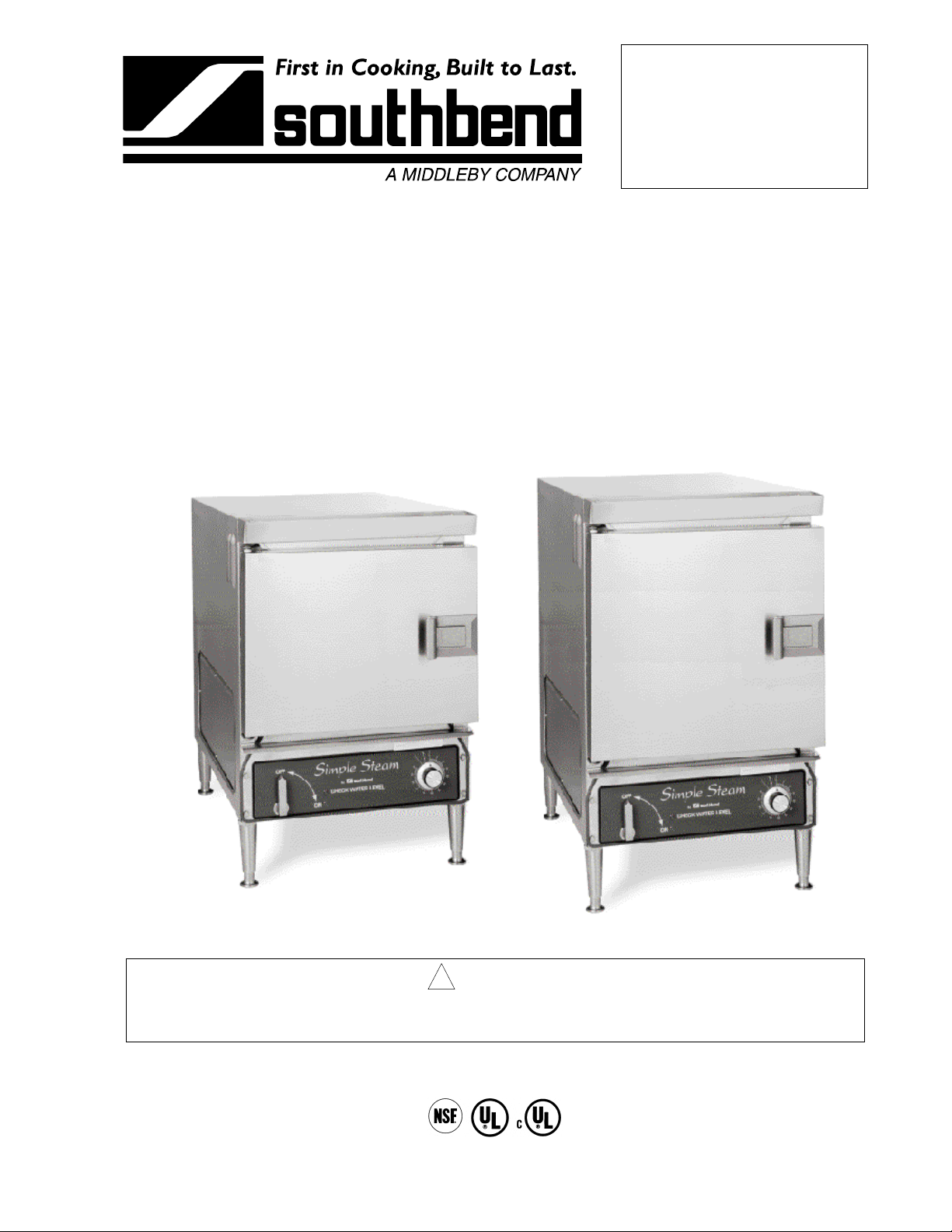
FOR MODEL EZ-3 and EZ-5
Simple Steam
COUNTERTOP STEAMERS
Model EZ-3 Model EZ-5
! WARNING
Improper installation, operation, service, or maintenance can cause property damage, injury, or death.
Read this manual thoroughly before installing and operating this equipment.
1100 Old Honeycutt Road, Fuquay-Varina, NC 27526
(800) 348-2558 or (919) 552-9161 • FAX (800) 348-2558 or (919) 552-9798
MANUAL 1178387 REV 2 COUNTERTOP STEAMER
$18.00 MANUAL SECTION ST
Page 2
SAFETY PRECAUTIONS
Before installing a nd opera ting this equipm ent, be sure e ver yone involv ed in its operat ion is f ully tr ained and
aware of precautions. Accidents and problems can be caused by failure to follow fundamental rules and
precautions.
The following s ymbols, found throughout this manual, alert you to potentially dangerous conditions to the
operator, service personnel, or to the equipment.
! DANGER
! WARNING
! CAUTION
NOTICE
This symbol warns of im mediate hazards which will result in severe injury or
death.
This symbol refers to a p otential hazard or uns afe practice wh ich could result in
injury or death.
This symbol refers to a p otential hazard or uns afe practice wh ich could result in
injury, product damage, or property damage.
This symbol refers to information that needs special attention or must be fully
understood, even though not dangerous.
! WARNING
FIRE HAZARD
For your safety, do n ot store or use gasol ine or other flamm able vapors and liquids in the vicinit y of
this or any other appliance.
Keep area around appliances free and clear of combustibles.
! WARNING
SHOCK HAZARD
Do not open panels that require use of tools.
Unit must be cleaned daily and properly maintained to reduce chances of unsafe operating
conditions.
! WARNING
BURN HAZARD
Watch for clogged drain - can crate burn hazard when door is opened.
Stand back when opening doors - hot steam or hot water may escape from steamer.
NOTICE
Be sure this Operator's Manual and important papers are given to the proper author ity to retain for
future reference.
PAGE 2OPERATOR’S MANUAL 1178387 REV 2
Page 3

MODEL EZ-3 & EZ-5 COUNTERTOP STEAMERS TABLE OF CONTENTS
Congratulations! You have purchased on e of the finest p ieces of heav y-duty comm ercial cook ing equipm ent
on the market.
You will find that your new equipm ent, like all Southbend equipment, has been desig ned and m anufactured
to meet the toughest standards in the indus try. Each piece of Southbend equipm ent is carefully eng ineered
and designs are verified through laboratory tests and field installations. With proper care and field
maintenance, you will experience years of reliable, trouble-free operation. For best results, read this
manual carefully.
RETAIN THIS MANUAL FOR FUTURE REFERENCE.
Table of Contents
Specifications..........................................................................................................................4
Installation...............................................................................................................................5
Operation ................................................................................................................................9
Cooking Hints........................................................................................................................10
Cleaning................................................................................................................................13
Troubleshooting ....................................................................................................................15
Parts......................................................................................................................................37
Limited Warranty...................................................................................................................41
Read these instructions carefully before attempting installation. Installation and initial startup should be
performed by a qualified installer. Unless the installation instructions for this product are followed by a
qualified service tech nician (a person experienced in and knowledge able with the insta llation of comm ercial
gas an/or electric cooking equipm ent) then the terms and conditi ons on the Ma nufactur er's Lim ited W arranty
will be rendered void and no warranty of any kind shall apply.
In the event you have questions concerning the installation, use, care, or service of the product, write to:
Technical Service Department
Southbend
1100 Old Honeycutt Road
Fuquay-Varina, North Carolina 27526 USA
The serial plate is located on the right side of the unit near the back and top (see Figure 2 on page 7).
OPERATOR’S MANUAL 1178387 REV 2PAGE 3
Page 4
SPECIFICATIONS MODEL EZ-3 & EZ-5 COUNTERTOP STEAMERS
SPECIFICATIONS
SPECIFICATIONS
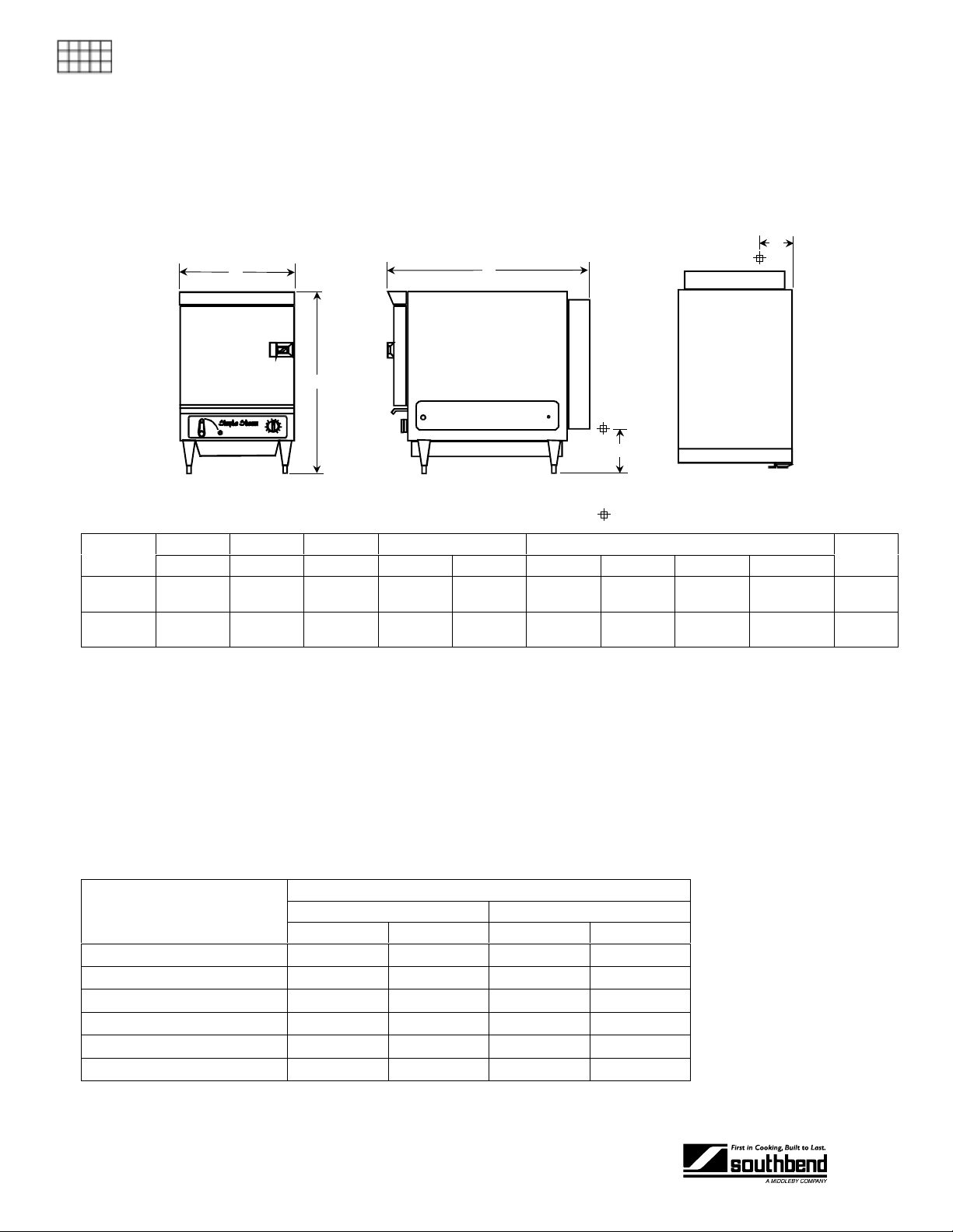
DIMENSIONS
E
A
B
FRONT VIEW
Model
EZ-3
EZ-5
Internal Dimensions: EZ-3: 13.5" W x 22" D x 9.5" H; EZ-5: 13.5" W x 22" D x 15.5" H
Width Height Depth Electrical Connection Crate Size
A B C D E Width Depth Height Volume
16.375"
416 mm
16.375"
416 mm
24.25"
616 mm
30.25"
762 mm
30.25"
768 mm6"153 mm
30.25"
768 mm6"153 mm
C
SIDE VIEW
2.44"
62 mm
2.44"
62 mm
508 mm
508 mm
20"
20"
D
TOP VIEW
= Electrical Connection Terminal Block
34"
864 mm
34"
864 mm
37"
940 mm
37"
940 mm
14.6 cu. ft.
0.41 cu. m.
14.6 cu. ft.
0.41 cu. m.
Crated
Weight
150 lbs.
68 kg.
175 lbs.
79 kg.
UTILITY INFORMATION
One electric connection is required.
IMPORTANT: UNIT MUST BE LEVEL FOR PROPER O PERATION. W ARRANTY WILL BE VOID ED FOR
IMPROPER INSTALLATION.
All units shipped per customer order, three phase or single phase.
Kit available for field conversion to three phase or single phase.
Max. Amps per Line
Total Connected Amps
1 Phase 3 Phase 1 Phase 3 Phase
208 V 60 Hz 40 24 57 33
220 V 50/60 Hz 38 23 54 31
240 V 60 Hz 35 21 49 29
380/220 V 50 Hz 23 14 31 19
415/240 V 50 Hz 21 13 29 17
480 V 60 Hz 18 13 25 15
Circuit must be wired for maximum amps at required voltage.
PAGE 4OPERATOR’S MANUAL 1178387 REV 2
EZ-3 EZ-5
Page 5
MODEL EZ-3 & EZ-5 COUNTERTOP STEAMERS INSTALLATION
INSTALLATION
! WARNING
DO NOT CONNECT 3/4” ID GREY HOSE IN R EAR OF UNIT TO ANYTHING. T HESE ARE VENT
HOSES AND MUST BE ALLOWED TO DRAIN INT O PAN. FAILURE T O COMPLY COULD CAUSE
A DANGEROUS PRESSURE RISE INSIDE OF THE STEAMER.
! CAUTION
Do not locate unit adjacent t o any high heat or greas e pr od uc in g p iece of eq ui pment, such as a range
top, griddle, fryer, etc., that could allo w radiant heat to raise th e exterior temperature of the steam
body above 130°F (54°C). DO NOT MOUNT ABOVE OTHER COOKING EQUIPMENT.
NOTICE
These installation procedures must be followed by qualified personnel or warranty will be void.
Local codes regarding install ation var y greatly from one area to an other. T he National F ire Protec tion
Association, Inc. states in its NFPA 96 latest edition that local codes are the “authority having
jurisdiction” when it com es to installation r equirements for equipment. Theref ore, installations shou ld
comply with all local codes.
The unit, when installed, must be electrically grounded and comply with local codes, or in the
absence of local codes with the National El ec tr ical Code ANSI /NF P A 70-latest edition.
INSTALLATION
Canadian installation must comply with CSA-Standard (C22.2 No. 109-M1981 General
Requirements-Canadian Electrical Code, Part II. 109-M1981) Commercial Cooking Appliances.
Step 1: Unpacking
IMMEDIATELY INSPECT FOR SHIPPING DAMAGE
All containers shou ld be examined for dam age before and during unlo ading. The freight car rier has
assumed responsibility for its safe transit and delivery. If damaged equipment is received, either
apparent or concealed, a claim must be made with the delivering carrier.
Apparent damage or l oss m u st be noted on the freight b ill at the t im e of deliver y. T he f reight bi ll m ust
then be signed by the c arrier representative (Dr iver). If the bill is not signed, the carrier ma y refuse
the claim. The carrier can supply the necessary forms.
A request for insp ection must be m ade to the carrier within 15 da ys if there is concea led damage or
loss that is not apparent until after the equipment is uncrated. The carrier should arrange an
inspection. Be certain to hold all contents plus all packing material.
OPERATOR’S MANUAL 1178387 REV 2 PAGE 5
Page 6
INSTALLATION MODEL EZ-3 & EZ-5 COUNTERTOP STEAMERS
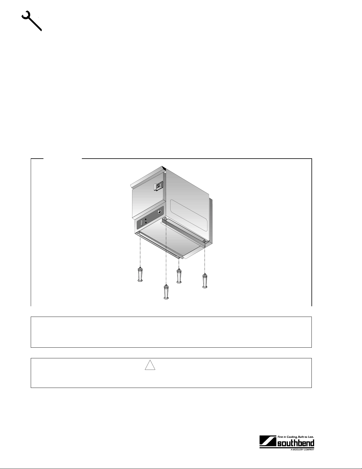
Step 2: Install the Legs
1. Uncrate carefully. Report any hidden damage to the freight carrier IMMEDIATELY.
2. Do not remove any tags or labels until unit is installed and working properly.
3. Remove placeholder bolts holding bottom cover onto unit and discard.
4. Screw legs into the bottom of the unit until approxim ately 1/4 " of thre ad is sho wing. T he legs wit h rubber
suction cups go on the back of unit.
5. Slip drain pan guides in to p lace between legs and bo ttom of steamer, as s ho wn in Figure 1, making sure
that pan stops are toward the rear of the unit.
6. Tighten legs, making sure that the pan guides stay seated against the leg threads.
INSTALLATION
7. To level the unit, adjust the base of unit’s legs.
8. Place custom drain pan under unit.
Figure 1
NOTICE
Unit must be level to assure maximum performance. Improper leveling may void warranty.
! CAUTION
WATER FROM A FULL CAVITY CANNOT BE HELD IN A 12" x 20" X 2½" PAN..
PAGE 6OPERATOR’S MANUAL 1178387 REV 2
Page 7
MODEL EZ-3 & EZ-5 COUNTERTOP STEAMERS INSTALLATION
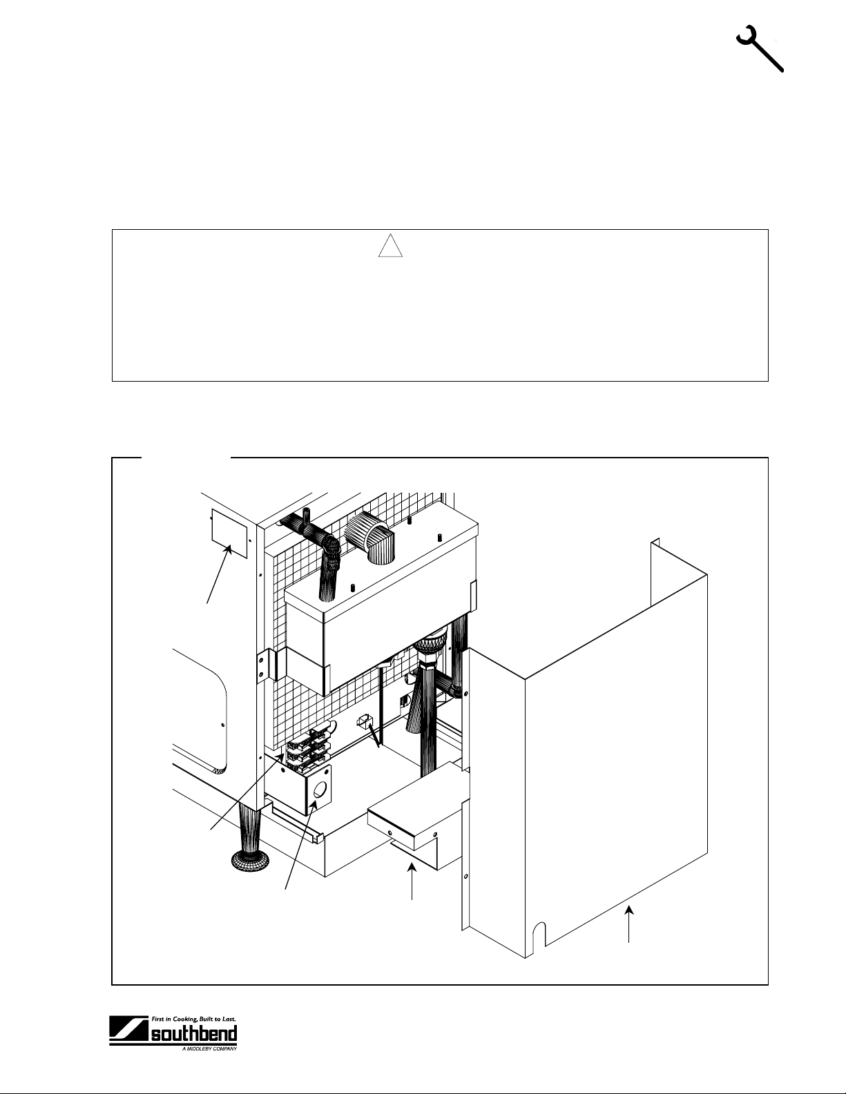
Step 2: Electric Connection
A field connection Fus e Block is located at the rear of the unit, lo wer left side. A hole is provided for a 3/4”
conduit fitting (solid or flex). Rear cover and fuse block cover m ust be rem oved to ga in acces s to fus e block.
Refer to Figure 2.
Be sure that the input voltage matches the requirement on the serial plate. The unit is factory wired per
customer order.
! WARNING
A POSITIVE GROUND CONNECTION IS ESSENTIAL. DO NOT ALLOW ANY TAMPERING OR
ADJUSTMENT OF ANY CONTROL OR WIRING. T HE UNIT IS FACTORY SET. ADJUSTING ANY
INTERNAL COMPONENT OTHER THAN THE MAIN FUSE BLOCK CAN VOID THE WARRANTY.
THIS UNIT REQUIRES A KIT TO BE FIELD CONVERTED FROM THREE-PHASE TO SINGLEPHASE OR VICE-VERSA. CONSULT FACTORY FOR PHASE CHANGES.
All 208-220-240 and 480 volt units will h ave three fuse bl ock sections , “L1-L2-L3”, for us e with either 3-wir e
3-phase or 2-wire, single-phase, 50 or 60 Hz. All 380V and 415V units will have four fuse block sections, “L1L2-L3-N,” for use with European style 4-wire 3-phase with neutral.
Figure 2
INSTALLATION
Serial
Plate
Fuse Block
3/4" Conduit
Fitting Hole
Fuse Block Cover
(shown removed)
Rear Cover
OPERATOR’S MANUAL 1178387 REV 2 PAGE 7
Page 8

INSTALLATION MODEL EZ-3 & EZ-5 COUNTERTOP STEAMERS
Step 3: Optional Floor Drain
The drain valve is 1/2’’ NPT. Posi tion the unit near, but not on top of, an ope n floor drain. Allow at le ast a 1"
air gap.
DO NOT directly plumb to the unit unless you also insta ll an “ope n funne l” downstr eam of this connect ion in
the drain system. The “open funnel” is int end ed t o eliminate an y water f r om entering the steamer because of
a blocked drain. An y connection that allows the build- up of back pressure in the unit (such as a reduct ion in
pipe size to a line smaller than 1/2’’or a 9 0 degree angle in the line pr ior to the “open f unnel” dr ain d ischarge
point) may cause personal or property damage and will therefore void the warranty. (See Figure 3)
Figure 3
INSTALLATION
PERFORMANCE CHECK
The following items should be checked within the first 30 days of operation by a qualified service technician.
1. Check doors for proper alignment.
2. Ensure proper opening and closing of doors.
3. Open door and remove cavity bottom cover, if present.
4. Ensur e that the li ght com es on when le ver is set to the ‘’ON” pos it ion.
5. An audible ‘’click” should be heard when the door switch actuator rod is depressed and held. This
indicates proper func tioning of the contactor as it closes. You should hear a sec ond audible ‘’click” (in
less than 75 seconds) as the contactor opens. Release rod.
6. Pour approximately 2 gallons of water into trough, ensuring that the cavity bottom is covered.
7. Depress and hold the door switch for 2 minutes. The contactor should close when the switch is first
depressed and stay closed during this period.
8. Close the door and wait approximately 12 minutes until the contactor closes, indicating the unit has
reached operating tem per ature.
PAGE 8OPERATOR’S MANUAL 1178387 REV 2
Page 9

MODEL EZ-3 & EZ-5 COUNTERTOP STEAMERS OPERATION
OPERATION
STARTUP
1. If the cavity bottom cover is present, open door and remove.
2. Turn lever to ‘’ON’’ position with door open.
3. Important: Pour water into trou gh above the door until water is obs erved pass ing through t he fill / drain
opening at left rear corner of cavity bottom.
4. Add additional water through trough or through door up to ‘’-WATER LEVEL-’’ mark.
NOTICE: WATER SPECIFICATION
To meet warranty requirements, supply water must meet the following specification:
Total Dissolved Solids (TDS)........... 60 PPM
Hardness.......................................... 2 Grains or 35 PPM
pH Factor ......................................... 7.0 to 7.5
5. Replace cavity bottom cover (if present).
6. Unit will be ready for cooking in approximately 12 minutes.
OPERATION
1. Suggested cooking times for various foods are shown in the table in the following section.
2. Pan specifications are shown on specifications page (page 4).
3. The door may be opened or closed at any time.
4. Unit will automatically idle at operatin g tem per ature when and if the door is c l os ed a nd there is no food in
the cavity.
5. Timer can be used as desired. However, it has no effect on unit operation.
6. Add proper am ount of water thr ough t he trough (abo ve the door) or direc tl y through the door when water
level is low.
7. If unit runs out of water the ‘’CHECK WATER LEVEL’’ light will illuminate. Follow step # 6, above.
SHUTDOWN
OPERATION
1. The custom drain pan or a 12” x 20”x 4” non-perfor ated stainless steel pan should be loc ated under the
unit at all times.
2. Turn lever to the “OFF” position.
3. Empty drain pan after allowing water to cool.
4. Remove pan guides and cavity bottom cover (if present).
5. Wipe out steamer (with Lime-A-Way or equivalent deliming solution as necessary), RINSE
THOROUGHLY WITH CLEAN WATER.
6. Ensur e drai n open ing is clear .
7. Replace pan guides and cavity bottom cover (if present).
8. Leave the door ope n at night af ter clean in g.
9. DO NOT USE high-chlorine or bleach solution for cleaning the door gasket.
10. DO NOT USE steel wool or other metallic pads in the steamer.
OPERATOR’S MANUAL 1178387 REV 2PAGE 9
Page 10

COOKING HINTS MODEL EZ-3 & EZ-5 COUNTERTOP STEAMERS
COOKING HINTS
COOKING TIPS
Schedule cooking of fresh vegetables so that they will be served soon after they are cooked. If it is
necessary to prepare t hem in advance, they can be plun ged into cold water, dr ained thoroughly and hel d
under refrigeration until needed for service.
Five pounds of c old cooked vege tables can be r eheated in the steam er in 5 to 10 m inutes, depe nding upo n
the variety.
SUGGESTED COOKING TIMES
Timer settings are for general gu idance only. Differenc es in food quality, size, sha pe, freshness, load si ze,
and desired degree of doneness must be taken into consideration and adjustments made in time, if
necessary.
Cooking Time
Product Weight Portions
(minutes) Pan Used
Asparagus
Fresh
Frozen Spears (Thawed)
Beans
COOKING HINTS
Green - Frozen, Cut
Green - Fresh
Wax - Frozen
Lima - Frozen
Broccoli
Spears -Fresh
Spears - Frozen (Thawed)
Brussel Sprouts
Fresh
Fresh
Carrots
Frozen - Whole Baby
Fresh - ¼-inch Bias Cut
Cabbage
Green, Cut Into Wedges
Red, Cut Into Wedges
Cauliflower
Fresh, Whole
Fresh, Whole
Frozen, Flowerettes
3½ lbs.
5 lbs.
5 lbs.
5 lbs.
5 lbs.
5 lbs.
4 lbs.
5 lbs.
5 lbs.
5 lbs.
5 lbs.
5 lbs.
2 lbs.
2 lbs. 12 oz.
5 lbs.
14 (4 oz.)
20 (4 oz.)
20 (4 oz.)
20 (4 oz.)
20 (4 oz.)
20 (4 oz.)
16 (4 oz.)
20 (4 oz.)
20 (4 oz.)
20 (4 oz.)
20 (4 oz.)
20 (4 oz.)
24
16
8 (4 oz.)
11 (4 oz.)
20 (4 oz.)
8-10
9
12
15-17
13
10
10-12
8
15-17
13
12
12
15
18-20
9-10
15
10-12
Full/Perforated
Full/Perforated
Full/Perforated
Full/Perforated
Full/Perforated
Full/Perforated
Full/Perforated
Full/Perforated
Full/Perforated
Full/Perforated
Full/Perforated
Full/Perforated
Full/Perforated
Full/Perforated
Full/Perforated
Full/Perforated
Full/Perforated
Corn
Fresh, Cob, 4-5 Inch Ears
Frozen - Whole Kernel
Frozen - Cob, 6 Inch Ears
Table continues on next page.
PAGE 10 OPERATOR’S MANUAL 1178387 REV 2
5½ lbs.
5 lbs.
9 lbs.
15
20 (4 oz.)
14
13-15
8
12-14
Full/Perforated
Full/Perforated
Full/Perforated
Page 11

MODEL EZ-3 & EZ-5 COUNTERTOP STEAMERS COOKING HINTS
Table continuing from previous page.
Cooking Time
Product Weight Portions
Mixed Vegetables
Frozen 5 lbs. 20 (4 oz.) 12 Full/Perforated
Peas
Frozen 5 lbs. 20 (4 oz.) 8 Full/Perforated
Potatoes
Red Bliss - Whole
Russetts - Whole
Russetts - Peeled
Russetts 1-Inch Cubes
Spinach
Fresh, Leaf
Frozen, Chopped
Zucchini
Fresh - Slices ¼-inch Thick 5 lbs. 20 (4 oz.) 6-8 Full/Perforated
7 lbs.
8 lbs.
5 lbs.
5 lbs.
2½ lbs.
6 lbs.
28
20
12
20 (4 oz.)
10 (4 oz.)
24 (4 oz.)
(minutes) Pan Used
35
25-35
20
17
5
35
Full/Perforated
Full/Perforated
Full/Perforated
Full/Perforated
Full/Perforated
Full/Perforated
Broccoli
Spears -Fresh
Spears - Frozen (Thawed)
Eggs
Large - Hard Cooked 12 lbs. 12 15-16 ½ Perforated
Meats
Corned Beef
Hot Dogs, Thawed
Hot Dogs, Frozen
Fowl
Boneless Chicken Breast 4½ lbs. 12 (6 oz.) 15 Full/Perforated
Tamales, Frozen
Tortilla, Frozen 8-Inch
Beef Ravioli, Frozen 48 Ravioli
Elbow Macaroni 2 lbs.
Spaghetti
Egg Noodles 2 lbs.
4 lbs.
5 lbs.
6¾ lbs.
5 lbs.
5 lbs.
3 lbs.
4 Tortillas
(1 lb. 8 oz.)
Uncooked
2 lbs.
Uncooked
Uncooked
16 (4 oz.)
20 (4 oz.)
18 (6 oz.)
40 (2 oz.)
40 (2 oz.)
12 (4 oz.)
4
8 5-6 Full/Perforated
32 (2 oz.) 7 In Perforated Pan
32 (2 oz.) 14
32 (2 oz.) 10 Full/Perforated
10-12
8
2 hours
5
10
20
45 Seconds
Full/Perforated
Full/Perforated
Full
Full/Perforated
Full/Perforated
Full/Perforated
Half/Perforated
Nested in Solid Pan
In 4-Inch
Full/Perforated
COOKING HINTS
Converted Rice 2 lbs.
2½ Qts. Water
+ Oil & Salt
Navy Beans
Place beans in pan and cover with 3-quarts hot tap
water. Steam for 2 minutes; remove from steamer
and cover for 1 hour. Remove cover and place back
in steamer for 40 minutes.
Table continues on next page.
OPERATOR’S MANUAL 1178387 REV 2 PAGE 11
2 lbs. Full/Perforated
25 Full/Perforated
Page 12

COOKING HINTS MODEL EZ-3 & EZ-5 COUNTERTOP STEAMERS
Table continuing from previous page.
Cooking Time
Product Weight Portions
(minutes) Pan Used
Black Eyed Peas
Place beans in pan and cover with 3-quarts hot tap
water. Steam for 2 minutes; remove from steamer
and cover for 1 hour. Remove cover and place back
in steamer for 35 minutes.
Oysters 5 lbs. 16 Count 12 Perforated Pan
Shrimp, Fresh, Medium, Heads Removed 5 lbs. 6-7 Full/Perforated
Shrimp, Frozen, Large, Peeled & Deveined 5 lbs. 8 Full/Perforated
Lobster 1¾ lbs. 8 Full/Perforated
Alaskan King Crab Legs 1 lb. 4-5 Full/Perforated
Cherrystone Clams 5 lbs. 12 7 Full/Perforated
Fish Fillets 7½ lbs. 12 (10 oz.) 18 Full/Perforated
• For eggs cooked in the shell, adding salt to the cooking water increases cooking efficiency and decreases cooking
time. If the egg cracks, the white is cooked at the crack and is sealed right away.
• To avoid green yolk (which is a deposit of iron sulfide) chill the eggs immediately after removing from the steamer by
COOKING HINTS
plunging them into a cold water bath (preferably containing ice).
• A quick and easy way to cook eggs for a salad mixture is to crack them directly into a solid steam table pan which has
been lightly coated with salad oil. Do not mix. Steam until they are hard cooked. Remove and chop as you would for
egg salad. The job of peeling is eliminated.
• Transfer steamed hot chicken to deep pan, cover with Cacciatore Sauce and finish in oven. Bake 20 to 30 minutes.
May be held on steam table.
• Chicken, sausage, and/or fish may be browned in Infra-Red or Radiant Broiler after steaming by brushing with melted
margarine mixed with salad oil to give a golden brown color.
• Save juices from steamed chicken or turkey to make soups, sauces, or casserole dishes.
• Chicken may be steamed in advance and refrigerated for next day’s use. Be sure to bring product back to 180°F
before serving.
• Save the juice from the corned beef. After the cabbage has been steamed, place it in a solid pan and add the juice for
flavoring and holding on a steam table.
• Steaming brisket is a definite time saver. Boiling in water takes 40 to 50 minutes per pound. Using the Simple Steam
can save 50% in cooking time.
• Cabbage, when steamed, retains its color and wedge identity. It will not break apart as it does when boiled in an open
pot.
• When removing items prepared in a perforated pan, place a solid pan underneath the perforated pan with the cooked
food in order to prevent dripping on the floor.
• The Simple Steam is designed to accept standard 12 x 20 pans. Fractional size pans and dishes can be used as well
with the optional perforated shelf.
• For stirring, the pan does not have to be removed from the steamer. Pull pan 1/3 way out of the cavity and the entire
surface is accessible.
• The door may be opened at any time during operation to remove or add food.
2 lbs. Full/Perforated
Nested in Full Pan
2½-Inch Deep
Nested in Full
Hotel Pan
PAGE 12 OPERATOR’S MANUAL 1178387 REV 2
Page 13

MODEL EZ-3 & EZ-5 COUNTERTOP STEAMERS CLEANING
CLEANING
Southbend equipment is constructed with the best quality materials and is designed to provide durable
service when properl y maintained. To expect the b est performance, your equipment must be m aintained in
good condition and cleaned dail y. Naturally, the frequenc y and extent of cleaning depends on the amount
and degree of usage.
Following daily and more extensi ve peri odic maintenance proced ur es will incr e as e th e l if e of your equ ipment.
Climatic conditions (i.e., salt air, seasonings, and water quality) may result in the need for more thorough and
more frequent cleaning in order to keep equipment performing at optimal levels.
! WARNING: BURN HAZARD
For proper and safe operation, this steamer must be cleaned daily as described in this manual.
Failure to do so could result in serious injury or damage.
Drains must be kept clean and clear of debris.
! WARNING: SHOCK HAZARD
DO NOT GET WATER IN THE CONTROLS.
This could result in expensive repairs and/or electrical shock.
De-energize all power to equipment before cleaning the equipment.
DAILY CLEANING
• Remove pan guides and cavity bottom cover (if present).
• Wipe out steamer (with Lime- A-Way or equivalent delim ing solution as nec essary) and rinse t horoughly
with clean water.
• Make sure drain opening is clear.
• Replace pan guides and cavity bottom cover (if present).
• Leave the door open at night after cleaning.
• Do not clean the door gasket with a high-chlorine solution or bleach.
• Do not use steel wool or other metallic pads in the steamer.
PERIODIC CLEANING
• If lime or mineral deposit starts to buil d up in th e interi or, cle an the u nit b y using Sou thbend “desc aler” or
other non-caustic de liming solution. Fol low manufacturer’s r ecommended procedures. T horoughly rinse
out unit with clean water.
CLEANING
• To remove normal dirt, grease, or product residue from stainless steel, use ordinary soap and water
applied with a sponge or cloth. Dr y thoroughly with a clean cloth. Nev er use vinegar o r any corrosiv e
cleaner.
• Occasionally drain rear water box. T o remove grease and f ood splatter or condense d vapors that have
baked on the equipment, apply cleans er to a dam p cloth or s ponge a nd rub cle anser on th e metal i n the
direction of the polishing lines on the metal. Rub bi ng cleans er as gently as possible in t he d irec ti on of the
polished lines will not mar the finish of the stainless steel. NEVER RU B WITH A CIRCULAR MOTION.
Soil and burnt deposits which do not r esp ond to the above procedur e c an usually be rem oved by rubbing
OPERATOR’S MANUAL 1178387 REV 2 PAGE 13
Page 14

CLEANING MODEL EZ-3 & EZ-5 COUNTERTOP STEAMERS
the surface with SCOTCH-BRITE scouring pads. DO NOT USE ORDINARY STEEL WOOL, as any
particles left on the sur face will r ust and f urther sp oil the appe arance of the finish . NEVER U SE A W IRE
RUSH, STEEL SCOURING PAD, SCRAPER, FILE OR OTHER STEEL TOOLS. Surfaces which are
marred collect dirt more rapidl y and bec om e mor e diff icult to cl ean. M arring also increas es t he poss ibilit y
of corrosive attack. Refinishing may then be required.
SEMIANNUAL CLEANING
At least twice a year, have your Southbend Authorized Service Agency or another qualified service
technician clean and adjust the unit for maximum performance. Semiannual cleaning should include the
following:
1. Remove rear cover.
2. Place a (1) gallon container under the water seal box drain valve (see Figure 12 on page 29).
3. Open drain v al ve, and clos e va lve when box is fin ished dra ining.
4. Add one gallon of deliming solution to the trough above the door.
5. Add two gallons of deliming solution through the door into the cavity
6. Turn unit on, let run for 30 minutes.
7. Turn unit off and drain all solution from the cavity.
8. Drain solution from water seal box as in steps 2 and 3.
9. Fill unit with clean water THROUGH THE TROUGH and drain. Repeat 2 times.
Consult the Southbend Authorized P arts/Servic e Distributor list for th e Authorized Service Representat ive in
your area or contact Southbend at 1-800-348-2558 for this information.
CLEANING
PAGE 14 OPERATOR’S MANUAL 1178387 REV 2
Page 15

MODEL EZ-3 & EZ-5 COUNTERTOP STEAMERS TROUBLESHOOTING
TROUBLESHOOTING
This section contai ns a troub les hootin g k ey and ref erenced f lowcharts to ass ist a qual ifie d serv ice tech nic ian
in the servicing of a EZ-3 or EZ-5 Countertop Steamer.
TROUBLESHOOTING KEY
Find the symptom below that corresponds to the malfunction, then tur n to t he c orr esponding figure and pag e.
Follow the flowchart on that page until the problem is solved.
Symptom Page
Unit Not Heating Up, "ON" Light Not Lit 16
Unit Not Heating Up Properly or Not Cooking As Fast, "ON" Light Lit 17
Unit Using Excessive Amount of Water and/or Excessive Steam Coming from Vent Tube 18
"Check Water Level" Light Does Not Come On When Unit Runs Out of Water 19
Buzzer Does Not Come On 20
TROUBLESHOOTING FIGURES AND PROCEDURES
Figure and/or Procedure Page
Voltage Check at Control Panel Fuse Block 21
Heating Element Resistance Check (at contactor) 22
Main Fuse Replacement 23
Power Switch Continuity Check 24
Contactor Coil and MOV Check 25
Idle Element Resistance Check 26
Timer and Buzzer Check 27
Door Switch Continuity Check 28
Float Switch Continuity Check 29
High Limit Continuity Check 30
Time Delay Relay Check (EZ-3 only) 31
Controller Check (EZ-5 only) 32
Electric Schematic for 208-240 Volt 60 Hz or 220 Volt 50 Hz Model EZ-3 33
TROUBLESHOOTING
Electric Schematic for 480 Volt Model EZ-3 34
Electric Schematic for 208-240 Volt 60 Hz or 220 Volt 50 Hz Model EZ-5 35
Electric Schematic for 480 Volt Model EZ-5 36
OPERATOR’S MANUAL 1178387 REV 2PAGE 15
Page 16

TROUBLESHOOTING MODEL EZ-3 & EZ-5 COUNTERTOP STEAMERS
Unit Not Heating Up, "ON" Light Not Lit
Unit not heating up, "ON" light not lit.
Check that circuit breaker is ON and that proper voltage is
DISCONNECT POWER AT CIRCUIT BREAKER.
Remove control panel without disconnecting plug.
Check voltage between A and B on control panel fuse
No Yes
DISCONNECT POWER AT CIRCUIT BREAKER.
Check resistance between contactor terminals
(see Figure 5 on page 22).
No Yes
Replace elements and
(see Fig. 6 on page 23).
Is measured resistance
consistent with th e table in
Figure 5 (see page 22)?
main fu se s
Check main fuses and
replace as needed
(see Fig. 6 on page 23).
available at main fuse block.
Turn le ver to "ON " po sitio n.
Reconnect power.
(see Figure 4 on page 21).
Does voltage
meet specifications?
Check voltage across
terminals 1 and 6 of
terminal block
(see Fig. 4 on page 21).
Check voltage on side C and D on control panel
fuse block (see Fig. 4 on page 21).
Does voltage
meet specifications?
Che ck for sh ort circuit in
power switch (see Fig. 7
on page 24), contactor coil
and MOV (see Fig. 8 on
page 25), idle element
(see Fig. 9 on page 26),
and buzzer (see Fig. 10
on page 27). Replace as
nece ssa ry.
NoYes
No Yes
Test power switch or
adjust so that it is
actuated properly by cam
on valve shaft. Replac e
TROUBLESHOOTING
switch a s n e ce s s a ry
(see Fig. 7 on page 24).
Does volta ge
meet specifications?
PAGE 16 OPERATOR’S MANUAL 1178387 REV 2
Replace control panel
fuses.
Replace "ON" light;
continue on next page.
Page 17

MODEL EZ-3 & EZ-5 COUNTERTOP STEAMERS TROUBLESHOOTING
y
Unit Not Heating Up Properly or Not Cooking A s Fast, "ON" Light Lit
Unit not heating up properly, or not
cooking as fast, "ON" light lit.
Check all three main fuses, replace as necessary.
No Yes
Drain unit. Turn unit on with door open.
Add two gallons of water THROUGH
TROUGH. Close door, wait 10 minutes.
Does unit heat up?No Yes
Open door, depress
and hold switch
Does constactor
No Yes
"click" on and stay on for at
least 2 minutes?
Check and replace time
delay relay as necessary
(EZ-3 only, see Fig. 14
on page 31).
Remind operator of
proper filling procedure.
Is "CHECK WATER LEVEL"
light on with door closed?
Add water according to
start up instru ctions on
door. Wait 5 minutes,
light should go off.
No Yes
DISCONNECT POWER
AT CIRCUIT BREAKER
Check high limits and
replace as necessary
(see Fig. 13 on page 30).
Does unit have water?No Yes
Is bo ttom
of unit covered with
deposits?
Clean unit
(see page 13)
DISCONNECT POWER
AT CIRCUIT BREAKER
Remove control panel. Remove control panel.
Rem o ve do o r sw itch lead
wires f rom t e rminal block
positions 2 and 3.
Depress door switch and
check door switch lead
wires for continuit
(see Fig. 11 on page 28).
Replace door switch.
DISCONNECT POWER
AT CIRCUIT BREAKER
Check resistance between
contactor terminals and
replace any bad elements
(see Fig. 5 on page 22).
Continuity?No Yes
OPERATOR’S MANUAL 1178387 REV 2PAGE 17
Reconnect door switch
lead wires.
Remove rear cover.
Che ck flo a t switch for
continuity and clean
openings in float tube
(see Fig. 12 on page 29).
No Yes
Replace float switch
and clean tube.
Float
switch and float tube
OK?
Check and replace contactor
(see Fig. 8 on page 25) and
controller (EZ-5 only, see
Fig. 15 on page 32).
TROUBLESHOOTING
Page 18

TROUBLESHOOTING MODEL EZ-3 & EZ-5 COUNTERTOP STEAMERS
Unit Using Excessive Amount of Water and/or Excessive Steam Coming from Vent Tube
Unit using excessive amount of water
and/or excessive steam coming from
vent tube behind the unit.
DISCONNECT POWER
AT CIRCUIT BREAKER
Remove control panel,
but leave plug connected.
Disconnect wire C23 from term inal block position 3
(EZ-3) or wire C98 from controller (EZ-5), reconnect
power, turn unit on, wait 12 minutes.
Yes No
DISCONNECT POWER AT
CIRCUIT BREAKER
C heck tim e delay relay (EZ-3
only, see Figure 14 on pag e 31)
or controller (EZ-5 only, see
Figure 15 on pa ge 32). Replace
if necessary
Reconnect power.
Wait 12 minutes.
Yes No
Excessive steam?
DISCONNECT POWER AT
CIRCUIT BREAKER
Check float switch and float tube.
Replace float switch and c lean
float tube as nece ssary
(see Figure 12 on pag e 29).
Excessive stea m?
TROUBLESHOOTING
PAGE 18 OPERATOR’S MANUAL 1178387 REV 2
Che c k contactor and
replace as necessary
(see Figure 8 on page 25).
Reinstall control panel,
reconnect power.
Page 19

MODEL EZ-3 & EZ-5 COUNTERTOP STEAMERS TROUBLESHOOTING
"Check Water Level" Light Does Not Come On When Unit Runs Out of Water
"CHECK WATER LEVE L" light does not
come on when unit runs out of water.
Remove wire C17 (EZ-3) or C53 (EZ-5)
from "CH ECK WAT ER LE VEL " light a nd
check resistanc e acro ss light terminals.
Check High Limits
(se e Figure 13 on
Page 30) an d
replace as needed.
Is resistance over
100 Kohm?
YesNo
Replace light
OPERATOR’S MANUAL 1178387 REV 2PAGE 19
TROUBLESHOOTING
Page 20

TROUBLESHOOTING MODEL EZ-3 & EZ-5 COUNTERTOP STEAMERS
Buzzer Does Not Come On
Buzzer doe s not come on.
DISCONNECT POWER
AT CIRCUIT BREAKER
Remove co n trol panel.
Set time r for five minu tes.
Yes No
Remove buzzer
le ad wires
from time r.
Check timer
(see Fig ure 10
on page 27 ).
Yes No
Continuity?
Does timer
time down?
Replace
timer.
TROUBLESHOOTING
Replace
timer.
PAGE 20 OPERATOR’S MANUAL 1178387 REV 2
Replace
buzzer
(see Fig ure 10).
Page 21

MODEL EZ-3 & EZ-5 COUNTERTOP STEAMERS TROUBLESHOOTING
g
Figure 4
Voltage Check at Control Panel Fuse Block
Power Switch
"ON" Light
"CHECK WATER
LEVEL" Li
ht
C
Control
Panel
Fuse
Block
A
D
B
1. Disconnect power at circuit breaker.
2. Remove control panel without disconnecting plug.
3. Turn lever to “on” position.
4. Reconnect power.
5. Place leads as shown.
6. Check voltage.
Terminal Block
Door Switch
TROUBLESHOOTING
OPERATOR’S MANUAL 1178387 REV 2PAGE 21
Page 22

TROUBLESHOOTING MODEL EZ-3 & EZ-5 COUNTERTOP STEAMERS
Figure 5
Heating Element Resistance Check (at contactor)
C
B
A
Contactor
(top view)
1. Disconnect power at circuit breaker.
2. Remove control panel.
3. Place test leads between terminals A and C on left side of contactor.
4. Check the resistance and compare to the allowable range in the following table:
Model EZ-3
Voltage
208 8 to 16 6 to 12
220 9 to 18 7 to 13
240 11 to 21 8 to 15
380 28 to 53 21 to 39
415 34 to 63 24 to 46
480 45 to 84 33 to 61
Allowable Resistance (Ohms)
Model EZ-5
Allowable Resistance (Ohms)
5. Check resistance between terminals A and B and between terminals B and C similarly.
TROUBLESHOOTING
PAGE 22 OPERATOR’S MANUAL 1178387 REV 2
Page 23

MODEL EZ-3 & EZ-5 COUNTERTOP STEAMERS TROUBLESHOOTING
Figure 6
Main Fuse Replacement
Fuse Block
1. Disconnect power at circuit breaker.
2. Remove rear cover from unit.
3. Remove fuse block cover.
4. Check fuses for continuity.
5. Replace as necessary.
Fuse Block Cover
(shown removed)
Rear Cover
TROUBLESHOOTING
OPERATOR’S MANUAL 1178387 REV 2PAGE 23
Page 24

TROUBLESHOOTING MODEL EZ-3 & EZ-5 COUNTERTOP STEAMERS
Figure 7
Power Switch Continuity Check
Power Switch
"NO" Lead
1. Disconnect power at circuit breaker.
2. Remove control panel.
3. Turn Lever to ‘’ON’’ from ‘’OFF’’ and to ‘’OFF’’ from ‘’ON’’ ensuring that the power switch is
properly actuated.
4. Remove power switch lead wires from fuse block (note wire locations).
5. Place test leads on ‘’C’’ and ‘’NO’’ lead wires as shown.
"C" Lead
Fuse Block
6. Check for continuity with lever in ‘’OFF’’ position (there should be no continuity).
7. Check for continuity with lever in ‘’ON’’ posit io n (there should be continuity).
8. Repeat steps 5 - 7 with test leads between other pair of ‘’C’’ and ‘’NO’’ lead wires.
9. Place test lead on “NO” lead wire and other test lead on other “NO” lead wire.
10. Check for continuity with lever in “ON” position (there should be no continuity).
11. Reconnect wires or replace switch as necessary.
TROUBLESHOOTING
PAGE 24 OPERATOR’S MANUAL 1178387 REV 2
Page 25

MODEL EZ-3 & EZ-5 COUNTERTOP STEAMERS TROUBLESHOOTING
Figure 8
Contactor Coil and MOV Check
Actuator
C
B
A
TOP VIEW
1. Disconnect power at circuit breaker.
2. Remove control panel and disconnect nine-pin plug PL1.
3. Depress actuator on top of contactor. Actuator should travel freely and spring back when released.
4. Check for continuity between contacts A and D as shown in top view. There should be no
continuity.
5. Repeat Step 4 for contacts B and E and for contacts C and F.
F
E
D
MOV
LEFT SIDE VIEW
6. Place test leads on contactor coil terminal as shown in left side view.
7. Check resistance.
8. If resistance is not approximately 390 (+/- 40) ohms, remove MOV and recheck coil resistance. If
resistance is now approximately 390 (+/-40) ohms, replace MOV, otherwise replace contactor.
9. Reconnect all wires.
OPERATOR’S MANUAL 1178387 REV 2PAGE 25
TROUBLESHOOTING
Page 26

TROUBLESHOOTING MODEL EZ-3 & EZ-5 COUNTERTOP STEAMERS
Figure 9
Idle Element Resistance Check
Model EZ -3
Model EZ -5
High Limit
Idle Element Plug
1. Disconnect power at circuit breaker.
2. Remove control panel.
3. Disconnect idle element plug (PL3).
4. Place test leads as shown above.
5. Check to see if resistance is within +/- 10% of values in the following table:
Model EZ-3
Voltage
208 115 87
220 129 97
240 154 115
380 385 289
415 459 344
480 614 461
TROUBLESHOOTING
6. Remove one test lead, place on ground, check for short circuit.
Resistance (Ohms)
Model EZ-5
Resistance (Ohms)
PAGE 26 OPERATOR’S MANUAL 1178387 REV 2
Page 27

MODEL EZ-3 & EZ-5 COUNTERTOP STEAMERS TROUBLESHOOTING
Figure 10
Timer and Buzzer Check
Timer
Buzzer
1. Disconnect power at circuit breaker.
2. Remove control panel.
3. Set timer for one minute and allow to time out. If timer does not run, then replace.
4. Remove buzzer lead wires from timer and terminal block position 6, as shown.
5. Place test leads between positions 1 and 3 on the timer.
6. Check for continuity. If no continuity, replace timer.
7. Place test leads in terminals of buzzer lead wires.
8. Check physical condition of buzzer.
9. Check that resistance is approximately 3.4Kohms. Otherwise, replace buzzer.
TROUBLESHOOTING
OPERATOR’S MANUAL 1178387 REV 2PAGE 27
Page 28

TROUBLESHOOTING MODEL EZ-3 & EZ-5 COUNTERTOP STEAMERS
Figure 11
Door Switch Continuity Check
Model EZ-3
Terminal Block
1. Disconnect power at circuit breaker.
Model EZ-5
Door Switch
2. Remove control panel.
3. Depress and release door switch actuator rod to make sure door switch is properly actuated.
4. EZ-3: Remove door switch lead wires from terminal block positions 2 and 3, or
EZ-5: Remove door switch lead wires from terminal block position 1 and terminal 2 of the controller.
5. Place test lead as shown inside the terminal connectors of the lead wires.
6. Check for continuity - (there should be NO continuity).
7. Depress door switch actuator rod and check for continuity - (there should be continuity).
TROUBLESHOOTING
PAGE 28 OPERATOR’S MANUAL 1178387 REV 2
Page 29

MODEL EZ-3 & EZ-5 COUNTERTOP STEAMERS TROUBLESHOOTING
Figure 12
Float Switch Continuity Check
Coupling
Water Seal Box
Float Switch
Drain Valve
Rear View of Unit with Back Cover Removed
1. Disconnect power at circuit breaker.
2. Remove rear cover from unit.
3. Disconnect 2 pin float switch plug from mating plug on back of unit (PL2).
4. Drain water seal box by opening 3/8’’ drain valve on box.
5. Remove float switch from box by removing float switch fitting from coupling on box.
6. Make sure float travels freely along stem.
7. Place test leads in float switch connector as shown.
8. Hold float switch in same orientation as when installed.
9. Check continuity. There should not be continuity.
10. Flip float switch over.
11. Check for continuity. There should be continuity. Replace as necessary.
12. Check 0.060 passages in float tube. Clean if necessary.
TROUBLESHOOTING
OPERATOR’S MANUAL 1178387 REV 2PAGE 29
Page 30

TROUBLESHOOTING MODEL EZ-3 & EZ-5 COUNTERTOP STEAMERS
Figure 13
High Limit Continuity Check
Model EZ-3
C16
C19
Terminal Block
Model EZ-5
C58
C59
1. Turn unit off.
2. Wait for cavity bottom to cool to touch.
3. Disconnect power at circuit breaker.
4. Remove control panel without disconnecting plug.
5. EZ-3: Remove wires C16 and C19 from terminal block positions 1and 2, as shown; or
EZ-5: Remove wires C58 and C59 from terminal block positions 5 and 6, as shown.
6. EZ-3: Place test leads as shown inside the terminal connectors of wires C16 and C19, or
EZ-5: Place test leads as shown inside the terminal connectors of wires C58 and C59.
7. Check for continuity.
8. If no continuity, disconnect each high limit switch individually and check for continuity. Replace
switches that do not have continuity. (See Figure 9 for typical high limit switch location).
9. EZ-3: Reco nn ec t wires C16 and C19; or
EZ-5: Reconnect wires C58 and C59.
10. Reconnect power at circuit breaker.
11. Dry cavity bottom with cloth.
12. Turn unit on with door closed.
13. Wait 6 minutes.
TROUBLESHOOTING
14. Disconnect power at circuit breaker.
15. EZ-3: Remove wires C16 and C19; or
EZ-5: Remove wires C58 and C59.
16. Remove wires from each high limit switch individually and check for continuity. Replace switches
that have continuity.
PAGE 30 OPERATOR’S MANUAL 1178387 REV 2
Page 31

MODEL EZ-3 & EZ-5 COUNTERTOP STEAMERS TROUBLESHOOTING
Figure 14
Time Delay Relay Check (EZ-3 only)
1. Disconnect power at circuit breaker.
2. Remove control panel, but leave plugged in.
3. Disconnect wire C23 from terminal block position 3.
4. Reconnect power.
5. Depress and hold door switch. Contactor should actuate and then deactuate in approximately 60
seconds.
6. If contactor fails to actuate or actuates but fails to deactuate, check potentiometer on top of time
delay relay. Make sure potentiometer is seated properly on time delay relay terminal and make sure
it is set to 60.
7. Depress door switch again. If contactor still fails to actuate and deactuate properly, replace time
delay relay.
TROUBLESHOOTING
OPERATOR’S MANUAL 1178387 REV 2PAGE 31
Page 32

TROUBLESHOOTING MODEL EZ-3 & EZ-5 COUNTERTOP STEAMERS
Figure 15
Controller Check (EZ-5 only)
C98
1. Disconnect power at circuit breaker.
2. Remove control panel, but leave plugged in.
3. Disc onnect wir e C98 fr om controller.
4. Reconnect power.
5. Use a spacer to hold door switch in closed position. Contactor should actuate and then deactuate
in less than 60 seconds.
6. If contactor fails to actuate (or actuates but fails to deactuate), replace controller.
7. With spacer still in place and door open, momentarily reconnect wire C98 and then disconnect.
8. Controller should actuate, then deactuate 10 seconds after C98 is disconnected.
9. If contactor fails to actuate (or actuates but fails to deactuate), replace controller.
TROUBLESHOOTING
PAGE 32 OPERATOR’S MANUAL 1178387 REV 2
Page 33

MODEL EZ-3 & EZ-5 COUNTERTOP STEAMERS TROUBLESHOOTING
Figure 16
Electric Schematic for 208-240 Volt 60 Hz or 220 Volt 50 Hz Model EZ-3
OPERATOR’S MANUAL 1178387 REV 2PAGE 33
TROUBLESHOOTING
Page 34

TROUBLESHOOTING MODEL EZ-3 & EZ-5 COUNTERTOP STEAMERS
Figure 17
Electric Schematic for 480 Volt Model EZ-3
TROUBLESHOOTING
PAGE 34 OPERATOR’S MANUAL 1178387 REV 2
Page 35

MODEL EZ-3 & EZ-5 COUNTERTOP STEAMERS TROUBLESHOOTING
Figure 18
Electric Schematic for 208-240 Volt 60 Hz or 220 Volt 50 Hz Model EZ-5
OPERATOR’S MANUAL 1178387 REV 2PAGE 35
TROUBLESHOOTING
Page 36

TROUBLESHOOTING MODEL EZ-3 & EZ-5 COUNTERTOP STEAMERS
Figure 19
Electric Schematic for 480 Volt Model EZ-5
TROUBLESHOOTING
PAGE 36 OPERATOR’S MANUAL 1178387 REV 2
Page 37

MODEL EZ-3 & EZ-5 COUNTERTOP STEAMERS PARTS
PARTS
NOTICE
INSTALLATION OF OTHER THAN GENUINE SOUTHBEND PARTS WILL VOID T HE WARRANTY
ON THIS EQUIPMENT.
The serial plate with volta ge, model, an d serial inform ation is locate d on the right sid e of the steam er cavity
on the upper rear cor ner. On single units a sec ond tag is located on t he face of the door which will show
only model and serial number. On tandem units, a second ta g is on t he r i ght s ide of the r i ght un it a nd t he lef t
side of the left unit.
Replacement parts may be ordered either thr ough a Southbend Auth orized Parts Dis tributor or a S outhbend
Authorized Service Agency.
When ordering parts, please suppl y the Model Number, Serial Number, Part Num ber, Description, Finish,
and Electrical Character istic s as appl icab le.
For parts not listed, consult a Southbend Authorized Parts Distributor or Southbend Authorized Service
Agency. Consult the Southbend Authori zed Parts/Servic e Distributor list f or the Authorized P arts supplier in
your area. If this list is not available, call Southbend at 1-800-348-2558 to obtain this list.
Parts for Simple Steam Countertop Steamer
EZ-3 Part Number EZ-5 Part Number Description
PH-422 PH-422 BELLEVILLE WASHER, 1/4 ID
1332076 1332076 BLANK, DOOR HINGE
1178266 1178266 BOX WELD ASM.,REAR
1178651 1178651 BRACKET, COMPONENT SIMPLE
1178534 1178534 BRACKET, ON/OFF SWITCH
1178525 1178525 BRACKET, VENT TUBE
1178411 1178411 BRACKET,WIRE HANGER
1177770 1177770 BUSHING, VALVE LEVER MOUN
1178389 BUSSMAN FUSE BLOCK,30A
1178494 1178494 BUSSMAN FUSE BLOCK,60A 48
1175708 1175708 BUZZER, ADJUSTABLE, 220V,
1178276 1178276 CAM ACTUATOR, STEAMER
1178370 CAVITY INSULATION
1178299 1181019 CAVITY WELD ASM
1178256 1178256 CLAMP, HEATER
1176561 CLEANING INSTRUCTIONS,RS1161525 1161525 CONTACTOR, 2-POLE,240V,30
1173448 CONTACTOR, 63A,240V COIL
1181032 CONTACTOR, DP, 60 FLA
1178397 1181042 CONTROL PANEL S/A
1178311 1178311 CONTROL PANEL W/A
1181038 CONTROLLER, EZ-5
1178442 1178442 COVER ASM.,POOL
1178524 1178524 COVER W/A, DRAIN BOX
1178552 1178552 COVER W/A, DRAIN
PARTS
OPERATOR’S MANUAL 1178387 REV 2PAGE 37
Page 38

PARTS MODEL EZ-3 & EZ-5 COUNTERTOP STEAMERS
Parts for Simple Steam Countertop Steamer
EZ-3 Part Number EZ-5 Part Number Description
1178265 1178265 COVER, BOTTOM
1178527 1181000 COVER, REAR STEAMER
1178255 1181009 COVER,EXTERIOR
1178657 COVER,EXTERIOR,STACKED
1179962 1179962 COVER,REMOVABLE BUSS
1176797 DESCALER, 3.5OZ PKG (100G)
1178167 1181015 DOOR ASSEMBLY COMPLETE
1178171 DOOR INSUL.BLOCK
1178522 1178522 DRAIN BOX WELD ASM.
1178410 1178410 DRAIN PAN WELD ASM.
1333045 DRAIN VENT TUBE ( AIR VEN
1178353 DUAL HEATING ELEMENT
1178359 DUAL HEATING ELEMENT
1178526 ELBOW, 90 DEG. 1 "NPT FEM,
1178656 1178670 ELBOW, 90 DEG, STR. 1/2"
1178354 ELEMENT BLO CK, 220V,CENTE
1178360 ELEMENT BLO CK, 220V,OUTER
1178355 ELEMENT BLO CK, 240V,CENTE
1178361 ELEMENT BLO CK, 240V,OUTER
1178358 ELEMENT BLO CK, 480V,CENTE
1178364 ELEMENT BLO CK, 480V,OUTER
1178332 1178332 FITTING,3/4 HOSE ID X 1/2
1178423 FITTING,3 /4" KYNAR HOSE,E
1178422 1178422 FITTING,FLOAT SWITCH
PH-423 PH-423 FLANGE BUSHING, 1/4ID BRO
1178318 1181020 FRONT FRAME WELD ASM
1178317 1178317 FRONT TOP CROSSMEMBER W/A
1178545 1178545 FUSE, 10 AMP
1178392 FUSE, 2.5 AMP
1178390 FUSE, 30 AMP
1181024 FUSE, 35 AMP
1178495 FUSE, 50 AMP, CLASS G
1181026 FUSE, 60 AMP
1178391 1178391 FUSEBLOCK, CONTROLS
1178096 1181010 GASKET, DOOR
1178227 GASKET, SIDE PANEL
1178325 1178325 GASKET,CONTROL PANEL
1180953 1180953 HANGER,HOSE
1332048-1 1332048-1 HINGE, LT DOOR
1332048-2 1332048-2 HINGE, RT DOOR
1181041 HARNESS, WIRE, EZ-5
1178560 HEAT ELEMENT,DUAL COIL, 20
1178561 HEAT ELEMENT,DUAL COIL, 22
1178565 HEAT ELEMENT,DUAL COIL, 48
1178562 HEAT/ELEMENT,240V,DUAL CO
1178554 HEATING ELEMENT, 208V, EZ
1178555 HEATING ELEMENT, 220V, EZ
PARTS
1178556 HEATING ELEMENT, 240V
1178559 HEATING ELEMENT, 480V, EZ
PAGE 38 OPERATOR’S MANUAL 1178387 REV 2
Page 39

MODEL EZ-3 & EZ-5 COUNTERTOP STEAMERS PARTS
Parts for Simple Steam Countertop Steamer
EZ-3 Part Number EZ-5 Part Number Description
1178483 HOSE, 1 1/2"ID,SILCONE
1178386 1178386 HOSE,3/4" ID SILCONE
1178685 HOS E, OVERF LO W, 28"
1178369 1181021 INSULATION, BACK PANEL
1178371 1178371 INSULATION, BOTTOM
1181022 INSULATION,CAVITY,EZ-5
1181018 INSULATION, DOOR, EZ-5
1178418 1178418 INSULATION,FRONT CAVITY
4440478 4440480 KIT, DRAIN BOXES,STACK
1170337 1170337 KNOB
1175168 1175168 KNURLED INSERT, 3/8"
1177079 1177079 LATCH ARM, CAST
1177317 1177317 LATCH ASSEMBLY, STEAMERS
1177078 1177078 LATCH COVER PLATE, CAST
1181039 LE AD, ELEMENT EZ-5
1178485 1178485 LEG,4" S/S, EZ (FRONT)
1178486 1178486 LEG,4" S/S,EZ (REAR)
1179930 LEVER, VALVE
1178329 1178329 LIGHT,INDICATING,AMBER
1178330 1178330 LIGHT,INDICATING,RED
1175547 1175547 LUG, GROUNDING
1178374 1178374 MAIN POWER LEADS
1178387 1178387 MANUAL, EZ-3&5 STEAMER
1178367 1178367 METAL OXIDE VARISTOR
1178643 1178643 NIPPLE, CLOSE, 1/2" NPT
1146402 NUT 1/4-20, HEX HEAD
1177865 NUT, HEX, 5/8 -18, BRASS
1178351 NYLON INSERT NUT
PH-292 PH-292 NYLON WASHER
1178342 1178342 O-RING, VALVE SHAFT
1178344 1178344 PAN Z-BRACKET,LEFT
1178345 1178345 PAN Z-BRACKET,RIGHT
1178169 1181017 PANEL ASM.,DOOR
1178105 1181016 PANEL ASM.,INNER DOOR
1178106 1181001 PANEL, GASKET RETAINER
1177081 1177081 PIN, .250 DIA, SS, CAST L
1178393 PIN,COTTE R,SS,1/8"X 1 1/4
1172949 PIPE ALUM,1" SCHE DULE 40
PM-141 PM-141 PLUG BUTTO N, 1/4 NYLON
1178319 1178319 POLYPANEL W/TIMER
1178684 1178684 POT FILLER
1178352 POTENTIOMETER,TDR
1333041 1333041 RACK MOUNTING STUDS,1/4-2
1178337 RELAY, TIME DELAY, 120V
1177086 1177086 RETAINER, CAST LATCH
1178338 1178338 RETAINING RING
6600402 6600402 RING,RETAINING S.S.
1178343 ROLL PIN
1175712 1175712 S/A BUZZER, 220V
PARTS
OPERATOR’S MANUAL 1178387 REV 2PAGE 39
Page 40

PARTS MODEL EZ-3 & EZ-5 COUNTERTOP STEAMERS
Parts for Simple Steam Countertop Steamer
EZ-3 Part Number EZ-5 Part Number Description
1178347 1178347 SEAL,SHAFT
1178275 SHAFT, VALVE LEVER
1178373 1178373 SHIELD,HEAT TRANSFER
1177318 1177318 SHIM, CAST STRIKER
1178234 SIDE PANEL,SIMPLE STEAM
1181045 SIDE, RACK W/A
1172951 1172951 SLEEVE, RUBBER 1 1/4"ID X
1178113 SLIDE RACK, 3 PAN STEA MER
1178644 SLIDE RACK, 5 POS. 3 PAN
1179932 1179932 SPRING
1177082 1177082 SPRING, DOOR HANDLE
1178654 1178654 STAND W/DRAIN, EZ
1178655 1178655 STAND, EZ
1178379 1178379 STEAM TRAP
1177080 1177080 STRIKER, CAST
1178270 1178270 SWITCH ACTUATOR ROD
1178340 1178340 SWITCH, FLOAT
1178533 1178533 SWITCH, POWER S/A
1178430 1178430 SWITCH,DOOR S/A,SIMPLE ST
1181013 THERMOSTAT ASSEMBLY, F/F
1181012 THERMOSTAT ASSEMBLY, M/M
1174302 THERMOSTAT, E LEMENT, 2001
1178341 1178341 TIMER, MECHANICAL
1176388 1176388 TRANSFORMER, 480 TO 240,7
1178439 1178439 TROUGH SCREEN ASM.
1178261 1178261 TUBE & BOX TOP W/A
1178376 1178376 TUBE, VALVE ACTUATOR
1178388 1178388 VALVE LEVER WELD ASM
1178425 1178425 VALVE, 1/2" DRAIN,MODIFIE
1178444 1178444 VALVE, 3/8" BALL,NSF/FDA
1176878 VENT P IPE , 1" NIPPLE
1178683 VENT PIP E, 1" X 24.375"
1180460 WASHER, SEALI NG, #10
1178324 1178324 WATER TROUGH W/A
1178652 1181043 WIRE HARNESS SUPPL., 480V
1178394 WIRE HARNESS W/DISC TSTAT
1178650 1181040 WIRING, DIAGNOSTIC, 480V
1178395 1181037 WIRING, DIAGNOSTIC,208/22
PARTS
PAGE 40 OPERATOR’S MANUAL 1178387 REV 2
Page 41

MODEL EZ-3 & EZ-5 COUNTERTOP STEAMERS
LIMITED W ARRANTY
Southbend warrants that the equipment, as supplied by the factory to the original purchasers, is free from defects in
materials and workmanship. Should any part thereof become defective as a result of normal use within the period and
limits defined below, then at the option of Southbend such parts will be repaired or replaced by Southbend or its
Authorized Service Agency. This warranty is subject to the following conditions:
Repairs under this warranty are to be performed by a Southbend Authorized Service Agency. Southbend cannot be
responsible for charges incurred or service performed by non-Southbend Authorized Agencies. In all cases the closest
Southbend Authorized Service Agency must be used.
TIME PERIOD:
One year labor, one year parts effective from the date of original purchase. The authorized service agency may at his
option require proof of purchase.
Exceptions to standard warranty, effective within above limitations:
• Glass Windows, Door Seals, Rubber Seals, Light Bulbs, Ceramic Bricks,
• Sight Glasses, Cathodic Descalers or Anodes, Broiler, Briquettes and Drip Shields.......90 days material and labor
• Stainless Steel Fry Pot................................................4 years extended material warranty on fry pot on ly—no labor
• Stainless Steel Open Top Burners........................... 4 years extended material warranty on burners only—no labor
• Pressure Steam Boiler Shell.............................. Prorated 4 years extended warranty on boiler shell only—no labor
Boiler shells which have not been properly maintained will not be covered by warranty.
In all cases, parts covered by a five year warranty will be shipped FOB the factory after the first year.
EXCLUSIONS:
• Equipment failure relating to improper installation. Examples are: improper utility connection, improper utilities supply
and problems due to ventilation.
• Equipment that has not been properly maintained. Examples are: calibration of controls, adjustments to pilots and
burners, damage from improper cleaning, and water damage to controls.
• Equipment that has not been used in an appropriate manner, or has been subject to misuse or misapplication,
neglect, abuse, accident, damage during transit or delivery, fire, flood, riot, or act of God.
If the equipment has been changed, altered, modified or repaired by other than a qualified service technician during or
after the one year limited warranty period, then the manufacturer shall not be liable for any damages to any person or to
any property which may result from the use of the equipment thereafter.
Equipment failure caused by inadequate water quality is not covered under warranty. WATER QUALITY must not exceed
the following limits: Tota l Dissolved Solids (TDS) - 60 PPM (Parts Per Million). Hardness - 2 Grains or 35 PPM, PH
Factor - 7.0 to 7.5. Water pressure 30 PSI minimum, 60 PSI maximum. Boiler maintenance is the responsibility of the
owner and is not covered by warranty.
This warranty does not cover services performed at overtime or premium labor rates nor does Southbend assume any
liability for extended delays in replacing or repairing any items in the equipment beyond the control of Southbend.
"Southbend shall not be liable for consequential or special damages of any nature that may arise in connection with such
product or part." Should service be required at times which normally involve overtime or premium labor rates, the owner
shall be charged for the difference between normal service rates and such premium rates.
This warranty only covers product shipped into the 48 contiguous United States and Hawaii. There will be no labor
coverage for equipment located on any island not connected by roadway to the mainland.
This equipment is intended for commercial use only. Warranty is void if equipment is installed in other than commercial
application.
Warranty on all replacement parts which are replaced in the field by Southbend Authorized Service Agencies will be
limited to three months on labor, six months on materials (parts) effective from the date of installation. See LIMITED
WARRANTY - REPLACEMENT PARTS for conditions and limitations.
"THE FOREGOING WARRANTY IS IN LIEU OF ANY AND ALL OTHER WARRANTIES EXPRESSED OR IMPLIED
INCLUDING ANY IMPLIED WARRANTY OF MERCHANTABILITY OR FITNESS, AND CONSTITUTES THE ENTIRE
LIABILITY OF SOUTHBEND. IN NO EVENT DOES THE LIMITED WARRANTY EXTEND BEYOND THE DURATION
OF ONE YEAR FROM THE EFFECTIVE DATE OF SAID WARRANTY."
OPERATOR’S MANUAL 1178387 REV 2PAGE 41
Page 42

COUNTERTOP STEAMER
A product with the So uthbend name incor porates the best in dur ability and low m aintenance. We
all recognize, however, that replacement parts and occasional professional service may be
necessary to extend the useful life of this unit. When service is needed, contact a Southbend
Authorized Service Agenc y, or your dea ler. T o a void conf usion, alwa ys refer to the m odel num ber ,
serial number, and type of your unit.
Southbend
1100 Old Honeycutt Road, Fuquay-Varina, NC 27526
(800) 348-2558 or (919) 552-9161 • FAX (800) 348-2558 or (919) 552-9798
PAGE 42 OPERATOR’S MANUAL 1178387 REV 2
 Loading...