

Page 1
IMPORTANT FOR FUTURE REFERENCE
Please complete this information and retain this
manual for the life of the equipment:
Model #: ___________________________
Serial #: ___________________________
Date Purchased: ____________________
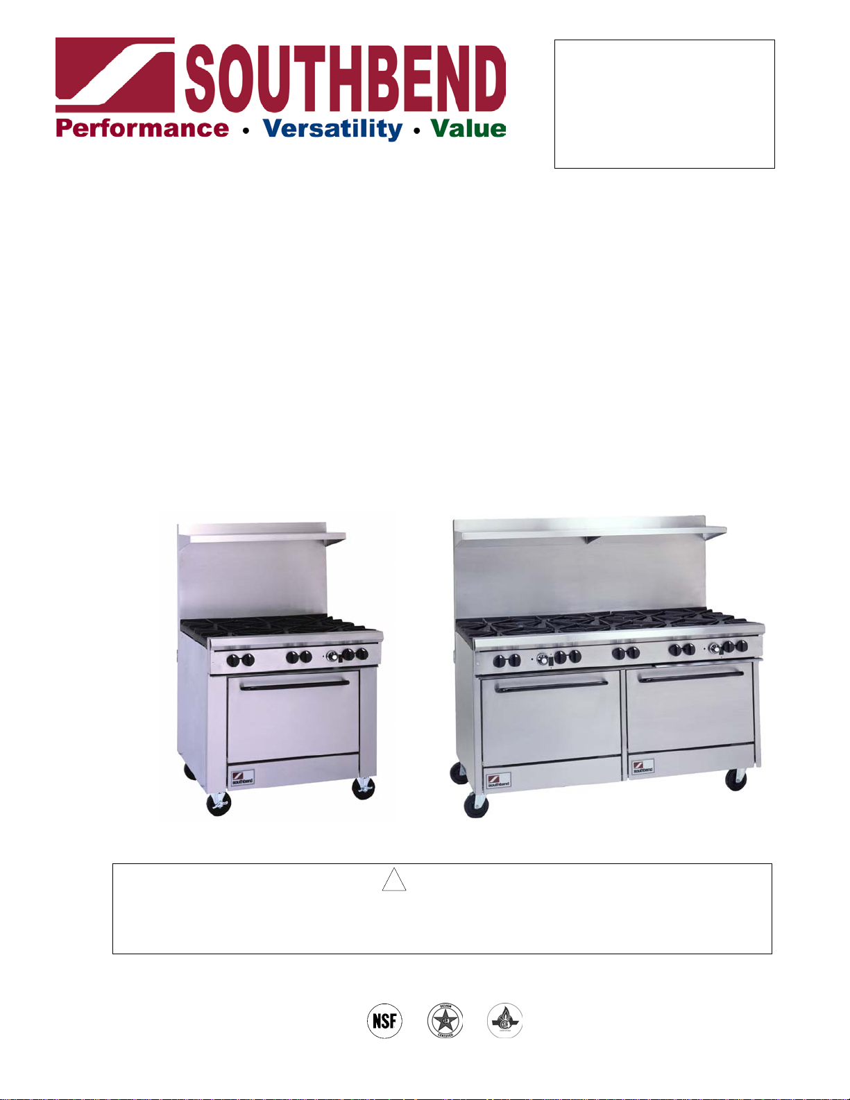
OPERATOR’S MANUAL
FOR MODEL 300
RESTAURANT RANGES
Ranges with Single Oven Base:
324E,
336A, 336A-1GL, 336A-2GL, 336A-2TL, 336A-2GR,
336A-2TR, 336A-3G, 336A-3T
336D, 336D-1GL, 336D-2GL, 336D-2TL, 336D-2GR,
336D-2TR, 336D-3G, 336D-3T
Ranges with Double Oven Base:
348EE, 348EE-2GL, 348EE-2TL, 348EE-2GR, 348EE-2TR
360AA, 360AA-2GL, 360AA-2TL, 360AA-2GR, 360AA-2TR,
360AA-3GL, 360AA-3TL, 360AA-3GR, 360AA-3TR,
360AD, 360AD-2GL, 360AD-2TL, 360AD-2GR, 360AD-2TR,
360AD-3GL, 360AD-3TL, 360AD-3GR, 360AD-3TR,
360DD, 360DD-2GL, 360DD-2TL, 360DD-2GR, 360DD-2TR,
360DD-3GL, 360DD-3TL, 360DD-3GR, 360DD-3TR
Ranges with Double Oven Base and Raised Griddle/Broiler:
360AA-2RR, 360AD-2RR, 360DD-2RR
Model 336D Model 360AA-2GR
! WARNING
Improper installation, adjustment, alteration, service or maintenance can cause property damage,
injury or death. Read the installation, operating and maintenance instructions thoroughly before
installing or servicing this equipment.
1100 Old Honeycutt Road, Fuquay-Varina, NC 27526
(919) 552-9161 • FAX (919) 552-9798
MANUAL 1182298 REV 3
$18.00
RESTAURANT RANGE
MANUAL SECTION RR
Page 2
MODEL 300 RESTAURANT RANGES
SAFETY PRECAUTIONS
Before installing and operating this equipment, be sure everyone involved in its operation is fully trained and
aware of precautions. Accidents and problems can be caused by failure to follow fundamental rules and
precautions.
The following symbols, found throughout this manual, alert you to potentially dangerous conditions to the
operator, service personnel, or to the equipment.
! DANGER
! WARNING
! CAUTION
NOTICE
This symbol warns of immediate hazards which will result in severe injury or
death.
This symbol refers to a potential hazard or unsafe practice which could result in
injury or death.
This symbol refers to a potential hazard or unsafe practice which could result in
injury, product damage, or property damage.
This symbol refers to information that needs special attention or must be fully
understood, even though not dangerous.
! WARNING
FIRE HAZARD
FOR YOUR SAFETY
Do not store or use gasoline or other flammable vapors and liquids in the vicinity of this or any other
appliance.
Keep area around appliances free and clear of combustibles.
Purchaser of equipment must post in a prominent location, detailed instructions to be followed in the
event the operator smells gas. Obtain the instructions from the local gas supplier.
! WARNING
Asphyxiation can result from improper ventilation. Do not obstruct the flow of combustion and
ventilation air to and from your cooking equipment.
NOTICE
Be sure this Operator’s Manual and important papers are given to the proper authority to retain for
future reference.
PAGE 2 OPERATOR’S MANUAL 1182298 REV 3
Page 3
MODEL 300 RESTAURANT RANGES TABLE OF CONTENTS
Congratulations! You have purchased one of the finest pieces of heavy-duty commercial cooking equipment
on the market.
You will find that your new equipment, like all Southbend equipment, has been designed and manufactured
to meet the toughest standards in the industry. Each piece of Southbend equipment is carefully engineered
and designs are verified through laboratory tests and field installations. With proper care and field
maintenance, you will experience years of reliable, trouble-free operation. For best results, read this
manual carefully.
RETAIN THIS MANUAL FOR FUTURE REFERENCE.
Table of Contents
Specifications .........................................................................................................................4
Installation ..............................................................................................................................9
Operation.............................................................................................................................. 16
Cooking Hints .......................................................................................................................19
Cleaning ...............................................................................................................................21
Adjustments..........................................................................................................................24
Troubleshooting....................................................................................................................31
Parts .....................................................................................................................................44
Read these instructions carefully before attempting installation. Installation and initial startup should be
performed by a qualified installer. Unless the installation instructions for this product are followed by a
qualified service technician (a person experienced in and knowledgeable with the installation of commercial
gas an/or electric cooking equipment) then the terms and conditions on the Manufacturer’s Limited Warranty
will be rendered void and no warranty of any kind shall apply.
In the event you have questions concerning the installation, use, care, or service of the product, write to:
Technical Service Department
Southbend
1100 Old Honeycutt Road
Fuquay-Varina, North Carolina 27526 USA
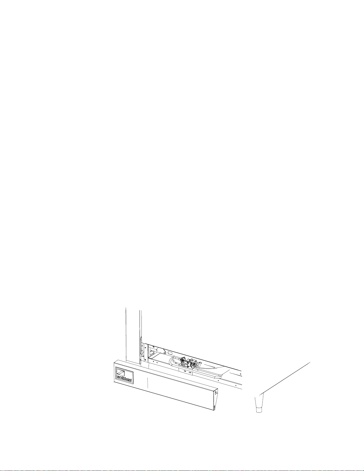
Lighting instructions and the serial plate are located on the interior side of the kick panel, as shown below.
Page 4

SPECIFICATIONS MODEL 300 RESTAURANT RANGES
ONS SPECIFICATI
SPECIFICATIONS
NOTICE
Local codes regarding installation vary greatly from one area to another. The National Fire Protection
Association, Inc. states in its NFPA 96 latest edition that local codes are the “authority having
jurisdiction” when it comes to installation requirements for equipment. Therefore, installations should
comply with all local codes.
Southbend reserves the right to change specifications and product design without notice. Such
revisions do not entitle the buyer to corresponding changes, additions, or replacements for previously
purchased equipment.
This product is intended for commercial use only, not for household use.
The installation must conform with local codes, or in the absence of local codes, with the National
Fuel Gas Code, ANSI Z223.1, Natural Gas Installation Code, CAN/CGA-B149.1, or the Propane
Installation Code CAN/CGA-B149.2, as applicable, including:
1. The appliance and its individual shutoff valve must be disconnected from the gas supply piping
system during any pressure testing of that system at test pressures in excess of 1/2 psi (3.45
kPa).
2. The appliance must be isolated from the gas supply piping system by closing its individual manual
shutoff valve during any pressure testing of the gas supply piping system at test pressures equal
to or less than 1/2 psi (3.45 kPa).
GAS SUPPLY
The Serial Plate is located in the compartment below the oven on the right side (on double units - left oven).
It indicates the type of gas the unit is equipped to burn. All Southbend equipment is adjusted at the factory.
Check type of gas on serial plate.
These models are design-certified for operation on natural or propane gases. For natural gas, the regulator is
set to deliver a 4" W.C. pressure to the manifold. For propane gas, it is set to deliver 10" W.C.
If applicable, the vent line from the gas appliance pressure regulator shall be installed to the outdoors in
accordance with local codes, or in the absence of local codes, with the National Fuel Gas Code, ANSI
Z223.1, Natural Gas Installation Code, CAN/CGA-B149.1, or the Propane Installation Code CAN/CGAB149.2, as applicable.
This appliance should be connected ONLY to the type of gas for which it is equipped.
An adequate gas supply is imperative. Undersized or low pressure lines will restrict the volume of gas
required for satisfactory performance. Fluctuations of more than 25% on natural gas or 10% on propane gas
will create problems and affect burner operating characteristics. A 1/8" pressure tap is located on the
manifold to measure the manifold pressure.
An adequate gas supply line to the unit should be no smaller than the inside diameter of the pipe from the
unit to which it is connected.
Purge the supply line to clean out dust, dirt, or other foreign matter before connecting the line to the unit.
All pipe joints and connections must be tested thoroughly for gas leaks. Use only soapy water for testing on
all gases. NEVER use an open flame to check for gas leaks. All connections must be checked for leaks after
the unit has been put into operation. Test pressure should not exceed 14" W.C.
PAGE 4 OPERATOR’S MANUAL 1182298 REV 3
Page 5
MODEL 300 RESTAURANT RANGES SPECIFICATIONS
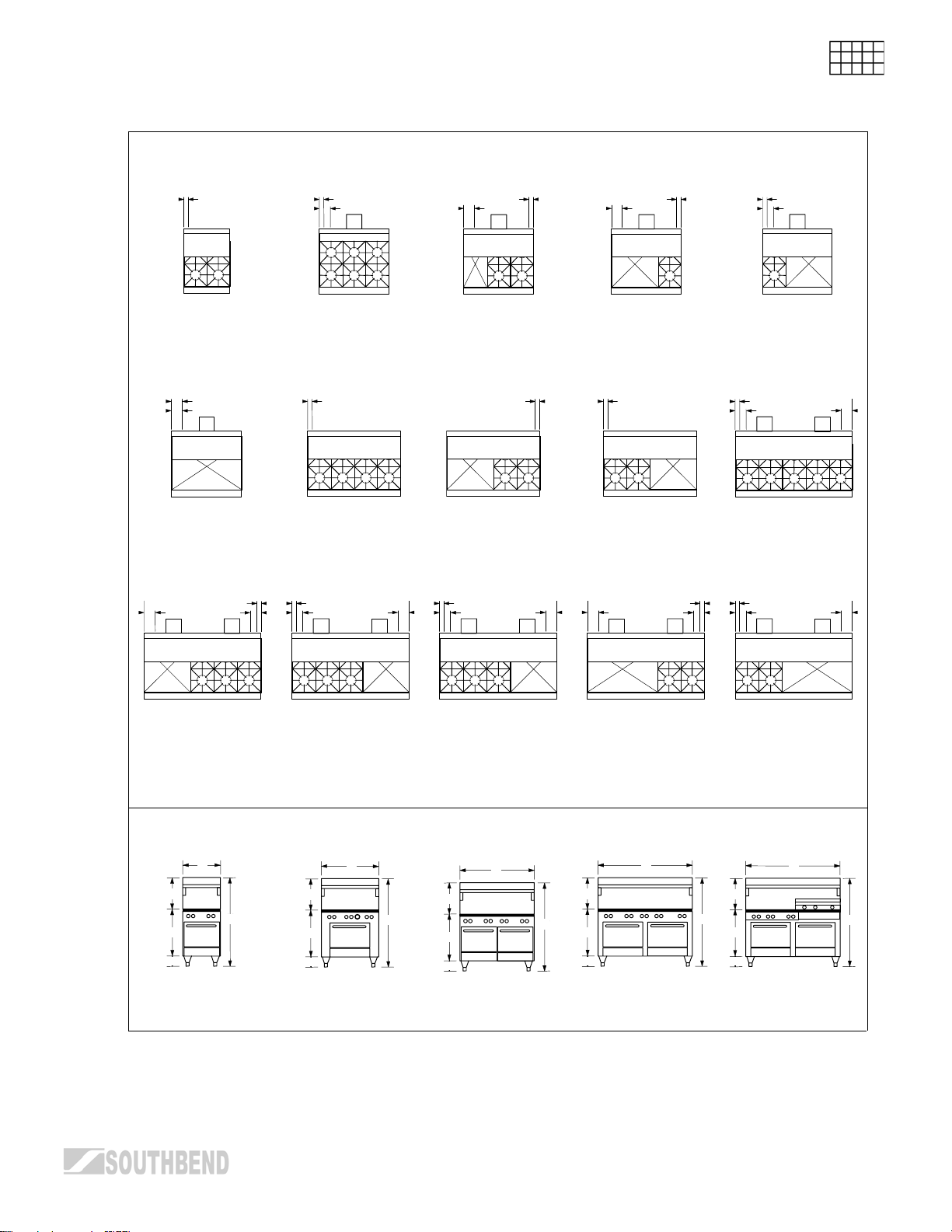
EXTERIOR DIMENSIONS
Top Views
O
O
R
O
R
O
R
O
R
SPECIFICATI
ONS
324E 336A
336D
O
R
336A-3G
336A-3T
336D-3G
O
348EE 348EE-2GL
336D-3T
R
O
R
O
R
R
360AA-2GL
360AA-2TL
360AD-2GL
360AD-2TL
360DD-2GL
360DD-2TL
360AA-2GR
360AA-2TR
360AD-2GR
360AD-2TR
360AD-2GR
360DD-2TR
348EE-2TL
O
R
360AA-2RR
360AD-2RR
360DD-2RR
336A-1GL
336D-1GL
O
R R
336A-2GL,
336A-2TL
336D-2GL
336D-2TL
O
348EE-2GR
348EE-2TR
360AA-3GL
360AA-3TL
360AD-3GL
360AD-3TL
360DD-3GL
360DD-3TL
336A-2GR
336A-2TR
336D-2GR
336D-2TR
O
R
R
360AA
360AD
360DD
O
R
O
R
R
360AA-3GR
360AA-3TR
360AD-3GR
360AD-3TR
360DD-3GR
360DD-3TR
Front Views
A
I
J
K
H
324E 336A
A
I
J
K
H
A
I
J
K
I
H
J
K
348EE 360AA
336D
Table continues on next page.
OPERATOR’S MANUAL 1182298 REV 3 PAGE 5
A
360AD
360DD
A
I
H
J
K
H
360AA-2RR
360AD-2RR
360DD-2RR
Page 6
SPECIFICATIONS MODEL 300 RESTAURANT RANGES
ONS
Table continuing from previous page.
Side Views
Page 7

MODEL 300 RESTAURANT RANGES SPECIFICATIONS
INTERIOR DIMENSIONS AND UTILITY CONNECTION DATA
Model
Number
324E 19.5"
336A 26.125"
336A-1GL
336A-1TL
336A-2GL
336A-2GR
336A-2TL
336A-2TR
336A-3G
336A-3T
336D 26"
336D-1GL
336D-1TL
336D-2GL
336D-2GR
336D-2TL
336D-2TR
336D-3G
336D-3T
348EE 19.5"
348EE -2GL
348EE -2GR
348EE -2TL
348EE -2TR
360AA 26.125"
360AA-2GL
360AA-2GR
360AA-2TL
360AA-2TR
360AA-3GL
360AA-3GR
360AA-3TL
360AA-3TR
360AA-2RR 26.125"
360AD 26.125"
360AD-2GL
360AD-2GR
360AD-2TL
360AD-2TR
360AD-3GL
360AD-3GR
360AD-3TL
360AD-3TR
360AD-2RR 26.125"
360DD 26"
360DD-2GL
360DD-2GR
360DD-2TL
360DD-2TR
360DD-3GL
360DD-3GR
360DD-3TL
360DD-3TR
360DD-2RR 26"
Left (or Only) Oven
Interior Dimensions
Width Depth Height Width Depth Height Open Oven Griddle
(660)
(664)
26.125"
(664)
26.125"
(664)
26.125"
(664)
(660)
26"
(660)
26"
(660)
26"
(660)
(660)
19.5"
(660)
(664)
26.125"
(664)
26.125"
(664)
(664)
(664)
26.125"
(664)
26.125"
(664)
(664)
(660)
26"
(660)
26"
(660)
(660)
* BTU values are for natural gas.
26.5"
(673)
24"
(610)
24"
(610)
24"
(610)
24"
(610)
26.5"
(673)
26.5"
(673)
26.5"
(673)
26.5"
(673)
26.5"
(673)
26.5"
(673)
24"
(610)
24"
(610)
24"
(610)
24"
(610)
24"
(610)
24"
(610)
24"
(610)
24"
(610)
26.5"
(673)
26.5"
(673)
26.5"
(673)
26.5"
(673)
14"
(356)
14.25"
(362)
14.25"
(362)
14.25"
(362)
14.25"
(362)
14"
(356)
14"
(356)
14"
(356)
14"
(356)
14"
(356)
14"
(356)
14.25"
(362)
14.25"
(362)
14.25"
(362)
14.25"
(362)
14.25"
(362)
14.25"
(362)
14.25"
(362)
14.25"
(362)
14"
(356)
14"
(356)
14"
(356)
14"
(356)
Right Oven
Interior Dimensions
- - - 4 @
- - - 6 @
- - - 4 @
- - - 2 @
- - - 0 1 @
- - - 6 @
- - - 4 @
- - - 2 @
- - - 0 1 @
19.5"
(660)
19.5"
(660)
26.125"
(664)
26.125"
(664)
26.125"
(664)
26.125"
(664)
(660)
(660)
(660)
(660)
(660)
(660)
(660)
(660)
26"
26"
26"
26"
26"
26"
26"
26"
26.5"
(673)
26.5"
(673)
24"
(610)
24"
(610)
24"
(610)
24"
(610)
26.5"
(673)
26.5"
(673)
26.5"
(673)
26.5"
(673)
26.5"
(673)
26.5"
(673)
26.5"
(673)
26.5"
(673)
14"
(356)
14"
(356)
14.25"
(362)
14.25"
(362)
14.25"
(362)
14.25"
(362)
14"
(356)
14"
(356)
14"
(356)
14"
(356)
14"
(356)
14"
(356)
14"
(356)
14"
(356)
Burners (# and BTU* each)
26,000
26,000
26,000
26,000
26,000
26,000
26,000
8 @
26,000
4 @
26,000
10 @
26,000
6 @
26,000
4 @
26,000
6 @
26,000
10 @
26,000
6 @
26,000
4 @
26,000
6 @
26,000
10 @
26,000
6 @
26,000
4 @
26,000
6 @
26,000
1 @
32,000
1 @
30,000
1 @
30,000
1 @
30,000
30,000
1 @
32,000
1 @
32,000
1 @
32,000
32,000
2 @
32,000
2 @
32,000
2 @
30,000
2 @
30,000
2 @
30,000
2 @
30,000
2 @
32,000
1 @
32,000
1 @
30,000
1 @
32,000
1 @
30,000
1 @
32,000
1 @
30,000
2 @
32,000
2 @
32,000
2 @
32,000
2 @
32,000
0 136,000 2.5"
0 186,000 2.5"
1 @
16,000
3 @
16,000
4 @
16,000
0 188,000 2.5"
2 @
16,000
3 @
16,000
4 @
16,000
0 272,000 2.5"
3 @
16,000
0 320,000 2.5"
3 @
16,000
4 @
16,000
2 @
12,000;
1@9,500
0 324,000 2.5"
3 @
16,000
4 @
16,000
2 @
12,000;
1@9,500
0 324,000 2.5"
3 @
16,000
4 @
16,000
2 @
12,000;
1@9,500
Total
BTU*
150,000 2.5"
130,000 2.5"
94,000 6"
168,000 2.5"
132,000 2.5"
96,000 6"
216,000 2.5"
264,000 2.5"
228,000 2.5"
249,500 2.5"
266,000 2.5"
230,000 2.5"
251,500 2.5"
268,000 2.5"
232,000 2.5"
253,500 2.5"
Gas Connection
Location
O P Q R
(64)
(64)
(64)
(64)
(152)
(64)
(64)
(64)
(152)
(64)
(64)
(64)
(64)
(64)
(64)
(64)
(64)
(64)
(64)
(64)
(64)
(64)
(64)
30.25"
(768)
30.25"
(768)
30.25"
(768)
30.25"
(768)
30.25"
(768)
30.25"
(768)
30.25"
(768)
30.25"
(768)
30.25"
(768)
30.25"
(768)
30.25"
(768)
30.25"
(768)
30.25"
(768)
30.25"
(768)
30.25"
(768)
30.25"
(768)
30.25"
(768)
30.25"
(768)
30.25"
(768)
30.25"
(768)
30.25"
(768)
30.25"
(768)
30.25"
(768)
Electric Connection
- -
24"
(610)
24"
(610)
24"
(610)
24"
(610)
- -
- -
- -
- -
- -
- -
24"
(610)
24"
(610)
24"
(610)
24"
(610)
24"
(610)
24"
(610)
24"
(610)
24"
(610)
24"
(610)
24"
(610)
24"
(610)
24"
(610)
Location
6"
(152)
6"
(152)
6"
(152)
6"
(152)
6"
(152)
6"
(152)
6"
(152)
6"
(152)
6"
(152)
6"
(152)
6"
(152)
6"
(152)
6"
(152)
6"
(152)
6"
(152)
6"
(152)
SPECIFICATI
ONS
OPERATOR’S MANUAL 1182298 REV 3 PAGE 7
Page 8
SPECIFICATIONS MODEL 300 RESTAURANT RANGES
VENTILATION
ONS
! WARNING
Improper ventilation can result in personal injury or death. Ventilation which fails to properly remove
SPECIFICATI
flue products can cause headaches, drowsiness, nausea, or could result in death.
All units must be installed in such a manner that the flow of combustion and ventilation air are not
obstructed. Provisions for adequate air supply must be provided. Do not obstruct the front of the unit
at the top by the control panel, or the bottom just below the oven compartment, as combustion air
enters through these areas.
NOTICE
Proper ventilation is the owner’s responsibility. Any problem due to improper ventilation will not be
covered by the warranty.
All units must be installed in such a manner that the flow of combustion and ventilation air are not
obstructed. Provisions for an adequate air supply must be provided. Do not obstruct the front or rear
of the unit, as combustion air enters through this area. Be sure to inspect and clean the ventilation
system according to the ventilation equipment manufacturer’s instructions.
Ranges with solid tops, such as griddles or hot tops, must always have venting for their flue products at the
rear of their burner compartments provided by the hollow area inside a shelf 21" high or a backsplash 17"
high. Lack of sufficient venting for the burners in these compartments will cause poor burner and pilot
operating characteristics, resulting in inefficient performance. Such conditions also cause high ambient
temperatures at the manifold area and create valve and thermostat problems.
Canopies are set over ranges, ovens, etc., for ventilation purposes. It is recommended that a canopy extend
6" past the appliance and the bottom edge be located 6'6" from the floor. Filters should be installed at an
angle of 45° or more from the horizontal. This position prevents dripping grease and facilitates collecting the
run-off grease in a drip pan, unusually installed with a filter. A strong exhaust fan tends to create a vacuum in
the room and may interfere with burner performance or may extinguish pilot flames. Fresh air openings
approximately equal to the fan area will relieve such a vacuum.
The exhaust fan should be installed at least 2" above the vent opening at the top of the unit.
If the unit is connected directly to an outside flue, a CSA design certified down draft diverter must be installed
at the flue outlet of the oven and connected to the flue.
In case of unsatisfactory performance on any appliance, check the appliance with the exhaust fan in the
“OFF” position. Do this only long enough to check equipment performance. Then turn hood back on and let it
run to remove any exhaust that may have accumulated during the test.
ELECTRICITY SUPPLY
Units with a convection oven require connection to a supply of electricity. The appliance, when installed,
must be electrically grounded in accordance with local codes, or in the absence of local codes, with the
National Electrical Code, ANSI/NFPA 70, or the Canadian Electrical Code, CSA C22.2, as applicable. An
electrical diagram is located on the rear of the range, near the motor.
Usually the range is furnished with one or two power cords (one for each oven), each with a standard 115V
60Hz single-phase prong plug. Total maximum amps for 115V units is 12.5.
The range can be ordered to operate on 208V 60Hz 1-phase or 3-phase current, in which case the electric
power supply must be wired to one or two junction boxes (one for each oven), each with a terminal block on
the rear of the range. Total maximum amps for 208V units is 8.1.
PAGE 8 OPERATOR’S MANUAL 1182298 REV 3
Page 9

Page 10
INSTALLATION MODEL 300 RESTAURANT RANGES
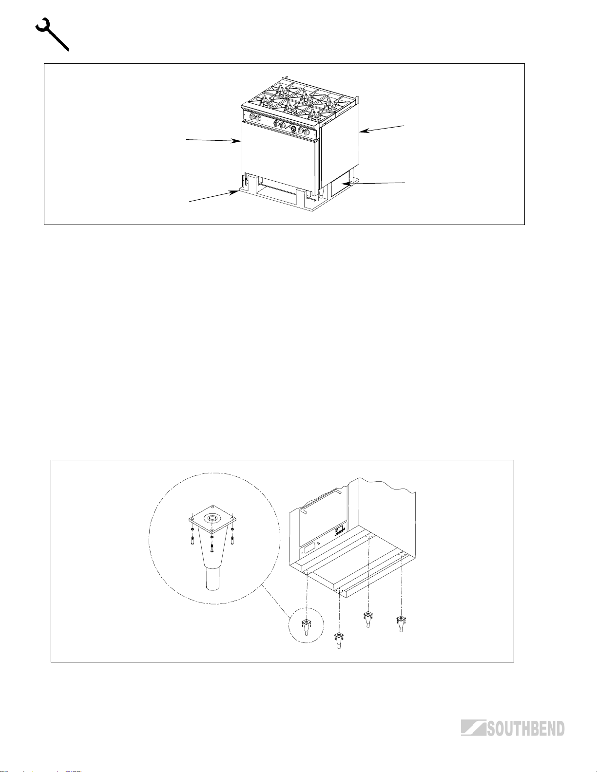
r
Base
Flue Rise
Shelf
Skid
INSTALLATION
Step 2a: Install the Legs
A set of four legs is packed with units ordered with legs. (For units ordered with casters, go to Step 2b.)
A threaded leg pad is fastened to the base frame at each corner. Each leg has a corresponding mating
thread. The legs can be adjusted to overcome a slightly uneven floor.
1. Raise unit sufficiently to allow leg pads and legs to be attached. For safety, “shore up” and support the
unit with an adequate blocking arrangement strong enough to support the load.
2. Attach the four leg pads to the bottom of the range using the lock washers and machine screws. The
mounting holes are pre-drilled and threaded.
3. Screw the legs into the holes in the centers of the leg pads.
4. Lower unit gently onto a level surface. Never drop or allow the unit to fall.
5. Use a level to make sure that the range surface is level. The legs can be screwed in or out to lower or
raise each corner of the range.
6. Go on to Installation Step 3.
PAGE 10 OPERATOR’S MANUAL 1182298 REV 3
Page 11
MODEL 300 RESTAURANT RANGES INSTALLATION
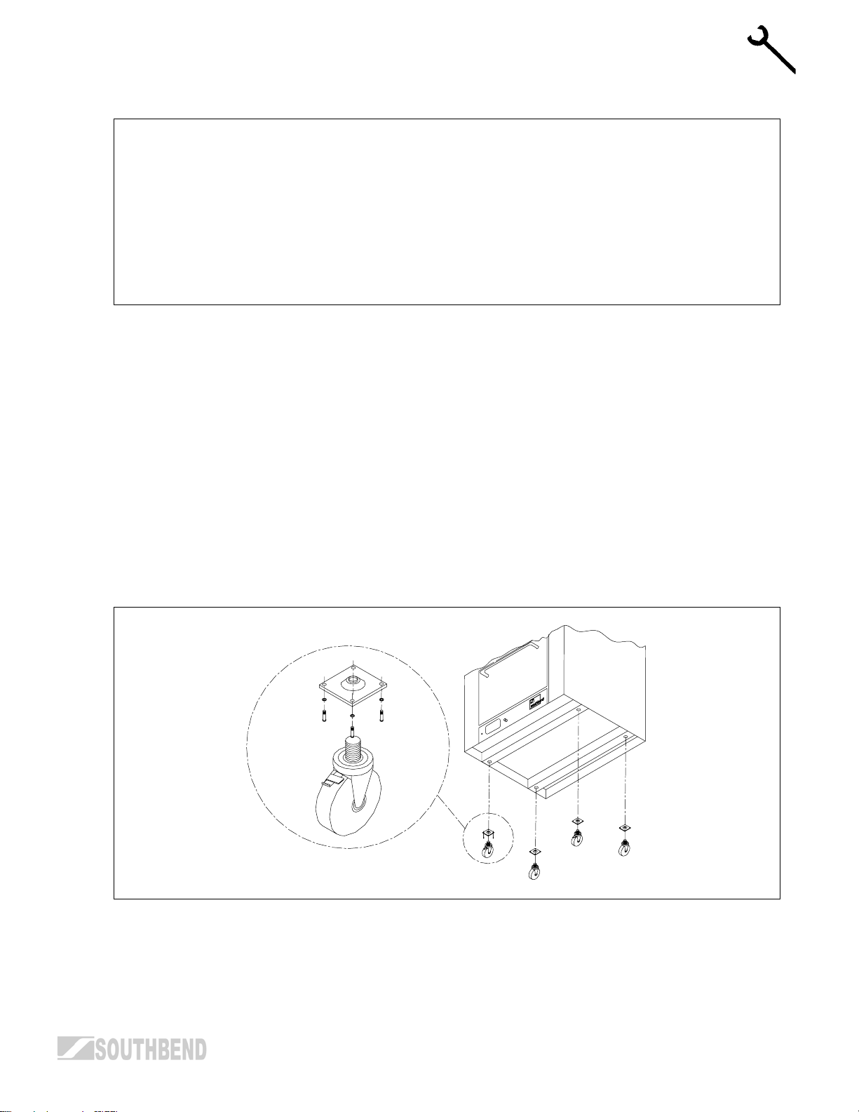
Step 2b: Install Casters and Restraint
NOTICE
For an appliance equipped with casters, (1) the installation shall be made with a connector that
complies with the Standard for Connectors for Movable Gas Appliances, ANSI Z21.69 or Connectors
for Moveable Gas Appliances, CAN /CGA-6.16, and a quick-disconnect device that complies with the
Standard for Quick-Disconnect Devices for Use With Gas Fuel, ANSI Z21.41, or Quick Disconnect
Devices for Use with Gas Fuel, CAN1-6.9, (2) adequate means must be provided to limit the
movement of the appliance without depending on the connector and the quick-disconnect device or
its associated piping to limit the appliance movement and (3) the restraining means should be
attached to a frame member on the back of the unit.
A set of four casters is packed with units ordered with casters (instead of legs).
A threaded leg pad is fastened to the base frame at each corner. Each caster has a corresponding mating
thread. The casters can be adjusted to overcome a slightly uneven floor. Casters are provided with a Zerk
fitting for proper lubrication when required.
1. Raise unit sufficiently to allow leg pads and casters to be attached. For safety, “shore up” and support
the unit with an adequate blocking arrangement strong enough to support the load.
2. Attach the four leg pads to the bottom of the range using the lock washers and machine screws. The
mounting holes are pre-drilled and threaded.
INSTALLATION
3. Screw the casters into the holes in the centers of the leg pads. Install the casters that have a locking
brake under the front of the unit.
4. Lower unit gently onto a level surface. Never drop or allow the unit to fall.
5. Use a level to make sure that the range surface is level. The casters can be screwed in or out to lower or
raise each corner of the range. After the unit has been leveled, tighten the lock nuts.
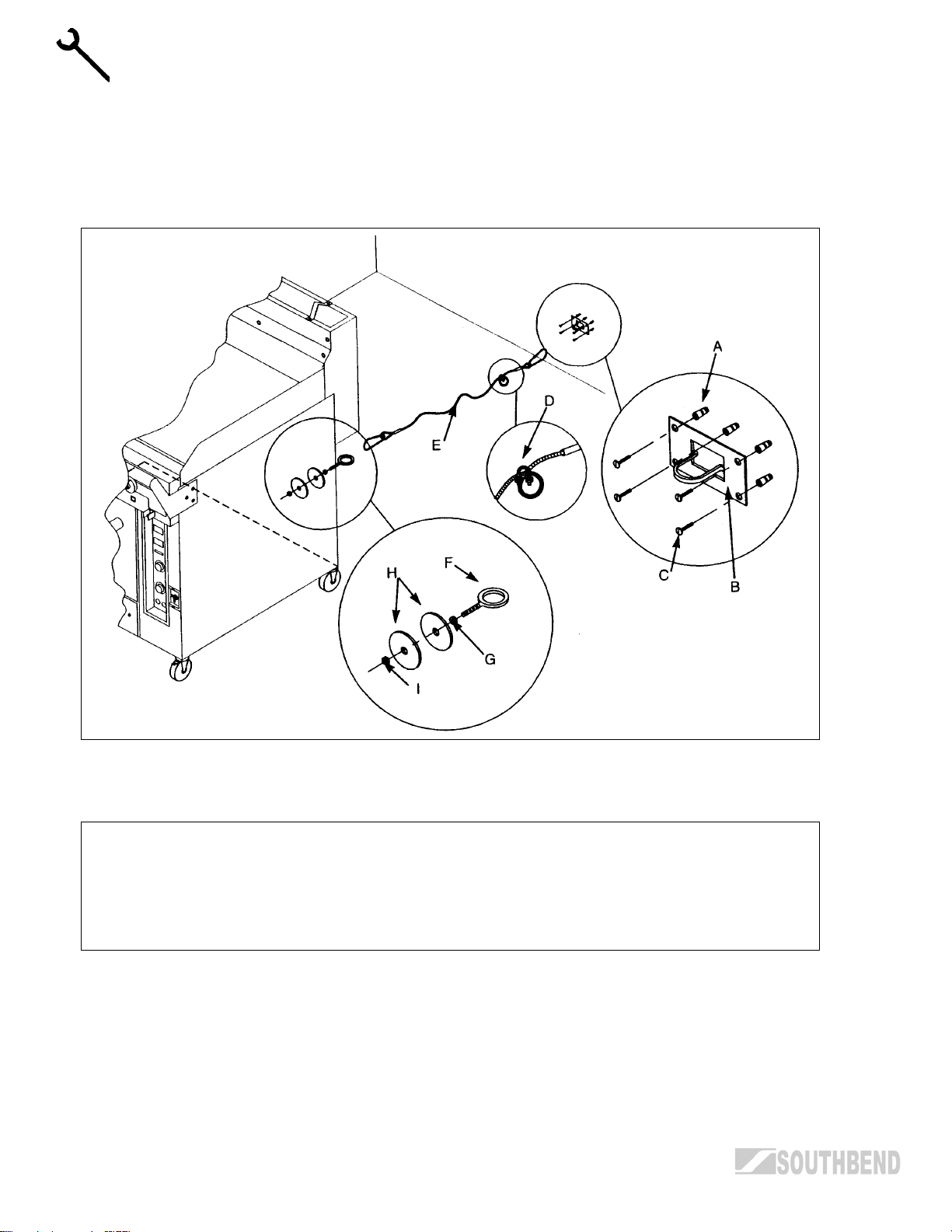
6. Secure the restraining-device bracket (item “B” in the following illustration) to a wall stud located as close
as possible to the appliance connector inlet and outlet connections. Use four #12 screws (items “C”) and
plastic anchors (items “A”) if necessary.
7. Install eye-bolt (item “F”) to a frame member on the rear of the equipment. After checking carefully
behind the frame member for adequate clearance, drill a 1/4" hole through the frame member.
OPERATOR’S MANUAL 1182298 REV 3 PAGE 11
Page 12
INSTALLATION MODEL 300 RESTAURANT RANGES
8. Thread hex nut (item “G”) and slide the washer (item “H”) onto the eye-bolt. Insert the eye-bolt through
the 1/4" drilled hole and secure with a washer (item “H”) and nylon lock nut (item “I”).
9. Using the spring-loaded snap hooks, attach the restraining device to the bracket and the eye-bolt.
10. Using the cable clamp (item “D”), adjust the restraining device extended length to prevent over-bending
or kinking of the appliance connector.
INSTALLATION
For units not equipped with flame safety devices, be sure all valves are turned off prior to disconnecting.
After reconnecting, be sure all valves are turned off and all pilots are lit.
NOTICE
Adequate means must be provided to limit the movement of the appliance without depending on the
connector and the quick-disconnect device or its associated piping to limit the appliance movement.
The restraining means should be attached to a frame member on the back of the unit.
PAGE 12 OPERATOR’S MANUAL 1182298 REV 3
Page 13

MODEL 300 RESTAURANT RANGES INSTALLATION
Step 3: Attach Flue Riser and Shelf Assemblies
1. Place the flue riser assembly on the range as shown on the appropriate diagram below.
2. Slide the flue riser assembly over the bayonets until it bottoms out, as shown below.
3. Secure ends of flue riser assembly with two (2) 1/4-20 x 3/4 hex head bolts, flat washers and
lockwashers
4. Attach the shelf assembly to the flue riser assembly.
INSTALLATION
Page 14
INSTALLATION MODEL 300 RESTAURANT RANGES
Step 4: Connect Electricity (for Models with Convection Ovens)
Wiring diagrams are located on the rear of the range. Be sure that the input voltage and phase match the
requirements shown on the serial plate.
Ranges ordered with a 115V, 60Hz, single-phase electrical rating are factory-supplied with one or two threewire cords (one for each oven), each with a three-prong plug that fits any standard three-prong grounded
receptacle. Single-oven units require a 15 ampere supply, while double-oven units require a 20 ampere
supply.
Ranges ordered with a 208/236V, 60Hz, single- or three-phase electrical rating are factory-equipped with
one or two two-pole terminal blocks (one for each oven), located behind cover plate(s) located on the rear of
the unit. To connect the supply wires, remove the appropriate cover plate. Route the supply wires and the
INSTALLATION
grounding wire through the strain relief fitting to the terminal block. Insert the supply wires, one each, into the
two poles of the terminal block and tighten the screws. Insert the ground wire into the grounding lug and
tighten the screw. Re-attach the cover plate.
Three phase units are wired as above, using only two supply wires. The third wire is not used and must be
properly terminated.
All units are shipped wired as specified by factory order. Conversion between single-phase and three-phase
can be accomplished by referring to phase loading and line amperes chart on wiring diagram for wire size
and ampere requirements.
Step 5: Connect Gas Supply
If this equipment is being installed at over 2,000 feet altitude and that information was not specified when
ordered, contact the appropriate authorized Southbend Service Representative or the Southbend Service
Department. Failure to install with proper orifice sizing will result in poor performance and may void the
warranty.
The Serial Plate is located in the compartment below the oven on the right side (on double units - left oven).
It indicates the type of gas the unit is equipped to burn. All Southbend equipment is adjusted at the factory.
Check type of gas on serial plate.
These models are design-certified for operation on natural or propane gases. For natural gas, the regulator is
set to deliver a 4" W.C. pressure to the manifold. For propane gas, it is set to deliver 10" W.C.
This appliance should be connected ONLY to the type of gas for which it is equipped.
An adequate gas supply is imperative. Undersized or low pressure lines will restrict the volume of gas
required for satisfactory performance. Fluctuations of more than 25% on natural gas or 10% on propane gas
will create problems and affect burner operating characteristics. A 1/8" pressure tap is located on the
manifold to measure the manifold pressure.
An adequate gas supply line to the unit should be no smaller than the I.D. of the pipe from the unit to which it
is connected.
Purge the supply line to clean out dust, dirt, or other foreign matter before
connecting the line to the unit.
! CAUTION
ALL PIPE JOINTS AND CONNECTIONS MUST BE TESTED THOROUGHLY FOR GAS LEAKS.
USE ONLY SOAPY WATER FOR TESTING ON ALL GASES. NEVER USE AN OPEN FLAME TO
CHECK FOR GAS LEAKS. ALL CONNECTIONS MUST BE CHECKED FOR LEAKS AFTER THE
UNIT HAS BEEN PUT INTO OPERATION. TEST PRESSURE SHOULD NOT EXCEED 14" W.C.
PAGE 14 OPERATOR’S MANUAL 1182298 REV 3
Page 15

MODEL 300 RESTAURANT RANGES INSTALLATION
Step 6: Check the Installation
1. Check that all screws and bolts are tightened.
2. Move the range into the position at which it will be operated.
3. Check that the range is level. If not, adjust the legs.
4. Check that the appropriate clearances are satisfied (see page 6).
Step 7: Adjust Air Shutters and Pilot Heights
All units are adjusted at the factory. However, burner air shutters and pilot heights should be checked at
installation and adjusted if necessary. On new installations, start with the top burner of the unit(s) furthest
from the gas input to the manifold. This will purge the system of air. Turn main gas supply “ON”.
Step 8: Condition Griddle Surfaces
New griddles should be carefully tempered and cared for in order to avoid possible damage. To break in a
new griddle, first wipe it clean. Next, light all the griddle burners and turn them to low for one hour. Then
gradually bring each griddle up to frying temperature. Next, spread three or four ounces of beef suet, or as a
substitute, baking soda, to season it. Never allow water on a hot griddle and never wash it with soap and
water.
INSTALLATION
OPERATOR’S MANUAL 1182298 REV 3 PAGE 15
Page 16
OPERATION MODEL 300 RESTAURANT RANGES
OPERATION
! DANGER
EXPLOSION HAZARD
In the event a gas odor is detected, shut down equipment at the main shut off valve. Immediately call
the emergency phone number of your gas supplier.
! CAUTION
To eliminate gas build up which could result in an explosion, in the event of main burner ignition
OPERATION
failure a five minute purge period must be observed prior to re-establishing ignition source.
! CAUTION
Top section pilots, when out, do not interrupt the flow of gas to the burners. Consequently, it is the
responsibility of the operator to check the ignition of the burners, immediately after burner value has
been turned “ON”. Should ignition fail after 10 seconds, turn off burners, wait 5 minutes, and then try
again.
LIGHTING AFTER GAS HAS BEEN SHUT OFF
When turning the main gas supply on after the gas supply has been shut off, do the following:
1. Make sure all of the control valves are in the “OFF” position.
2. Turn on the gas supply.
3. Light the pilots as described below.
4. Light oven first and then wait six minutes before lighting top section. This allows all air to be purged from
the range.
OPEN-TOP BURNER SECTIONS
Each open-top burner is controlled by a knob on the front control panel.
To light the pilots of an open-top burner section, do the following:
1. Turn all gas valves to the “OFF” position.
2. Check to make sure pilots are in the correct position.
3. Light the pilots.
4. Adjust the pilot flame as necessary.
PAGE 16 OPERATOR’S MANUAL 1182298 REV 3
Page 17

MODEL 300 RESTAURANT RANGES OPERATION
HOT TOP SECTIONS
Range can be ordered with a hot-top section replacing one or more open-top burner sections. Each hot-top
is controlled by a knob on the front control panel.
To light the pilots of a hot-top section, do the following:
1. Raise or remove hot-top plate. Every two burners have one pilot located at the front and in between
burners.
2. Light the pilot.
3. Pilot flame should be steady blue, large enough to effect ignition.
3. Turn burner valve completely on. The sharp blue flame should be approximately 1/4" to 3/8" high.
5. Replace hot top plate.
NON-THERMOSTATIC GRIDDLE SECTIONS
Ranges can be ordered with thermostatic or non-thermostatic griddle sections. Each griddle is controlled by
a knob on the front control panel.
At the end of each use, allow griddle to cool normally. After griddle has cooled, coat griddle surface with a
light film of cooking oil to protect surface from moisture.
To light the pilots of a non-thermostatic griddle section, do the following:
1. Raise griddle at front so it is approximately 8" high and block it with two (2) two-by-fours.
2. Ignite pilot tube located under all burners with port at each side of burners. Pilots are supplied and
adjusted by a common valve located below the filter on the manifold.
3. Burners should have 1/2" to 5/8" steady blue flame. Adjust if necessary.
4. Lower griddle into position and observe burner operating characteristics through holes in valve panel.
THERMOSTATIC GRIDDLES
Ranges can be ordered with thermostatic or non-thermostatic griddle sections. Each griddle is controlled by
a knob on the front control panel.
At the end of each use, allow griddle to cool normally. After griddle has cooled, coat griddle surface with a
light film of cooking oil to protect surface from moisture.
To light the pilots of a thermostatic griddle section, do the following:
1. Raise griddle at front so it is approximately 8" high and block it with two (2) two-by-fours.
OPERATION
2. The sensing bulbs must be fully inserted into their tubular holders, which are welded to the underside of
the griddle.
3. One pilot tube is located under all burners with ports at each side of the burners. Pilots are supplied and
adjusted by a common valve on the manifold. Ignite pilots.
4. Set thermostat dials to maximum, one at a time.
5. Burners should have 1/2" to 5/8" steady blue flame. Adjust if necessary.
6. Lower griddle carefully into position taking extreme care that capillary tubes are coiled under manifold in
valve panel compartment. NEVER leave any part of the capillary tube in the burner compartment.
7. Observe burner flame through holes in valve panel, turn thermostat dial at maximum for ten minutes,
then turn dial to “LOW” and adjust bypass on thermostat so there is a 1/8" minimum and 1/4" maximum
flame at each port.
OPERATOR’S MANUAL 1182298 REV 3 PAGE 17
Page 18

OPERATION MODEL 300 RESTAURANT RANGES
RAISED-GRIDDLE BROILER SECTION
Ranges can be ordered with a raised-griddle broiler section. Each raised-griddle broiler is controlled by a
knob on the front control panel.
At the end of each use, allow griddle to cool normally. After griddle has cooled, coat griddle surface with a
light film of cooking oil to protect surface from moisture.
To light the pilots of a raised-griddle broiler, do the following:
1. Remove griddle from unit.
2. Position ceramics on burners with projections pointing downward.
3. Light pilot tube ports (2 at each burner). Adjust pilot flame to be large enough to effect ignition.
4. Place griddle in position on range.
5. Turn valves completely on.
6. Burner should have 1/2" to 5/8" steady blue flame. Adjust if necessary.
SHUTDOWN OF ENTIRE RANGE
OPERATION
To place the range in a standby state (ready for use), do the following:
1. Turn all manual gas valves “OFF.”
2. Turn all thermostats to their lowest position.
To completely shut down the range for an extended period (or prior to disconnecting the gas supply), do the
following:
1. Turn all manual gas valves and pilots “OFF.”
2. Turn all thermostats to their lowest position.
3. Turn main supply gas valve “OFF.”
OVENS
Ranges can be ordered with standard or convection ovens. Each oven is controlled by a knob on the front
control panel.
To light the pilot of an oven, do the following:
1. Turn oven thermostat to “OFF” position.
2. For convection ovens, turn the fan switch to the “OFF” position.
3. Open door, remove oven bottom and fire plate to expose pilot and burner.
4. Open kick panel and depress red button on oven safety valve.
5. Light constant pilot (the pilot without capillary tube holder).
6. Replace fire plate and oven bottom.
7. Turn thermostat to desired temperature.
PAGE 18 OPERATOR’S MANUAL 1182298 REV 3
Page 19

MODEL 300 RESTAURANT RANGES COOKING HINTS
COOKING HINTS
COOKING TIPS (Convection-Type Oven Only)
A. FROZEN ENTREE PRODUCTS: Punch holes in lid before heating. Tent lid if product has a tendency to
stick, i.e., lasagna or macaroni and cheese. Use manufacturer’s convection oven directions for time and
temperature or reduce conventional oven temperature 50 degrees for a 6-1/2 size pan load. Some
products may cook in 10 to 15 minutes less time than recommended for convection ovens if prepared
from frozen in a 6 pan load.
B. FRUIT PIES: Use temperature and time from manufacturer’s directions for convection ovens for a 12 pie
load placed on 3 bun pans.
C. ROLLS – YEAST: Use temperature and time recommended by manufacturer for convection ovens for a
3 pan load.
D. POTATOES – PRE-BLANCHED, FROZEN: Spread on ungreased bun pans, 3 pans per load. Bake at
400°F, stirring once, for 15 to 18 minutes.
E. FISH PORTIONS – BREADED, PRE-COOKED: Use manufacturer’s recommended temperature and
time for convection oven for a 3 pan load.
COOKING HINTS
F. POTATOES – BAKING, 8 OZ. SIZE: Wash and wrap in potato foil. Place 30 potatoes on 18 x 24 bun
pan — 3 pans per load. Bake in 400°F oven for 1 hour.
G. TOP ROUND OF BEEF, NO. 168: Set oven at 250°F. Place trimmed roast on pan. For 14 - 16 pounds:
140° rare - 14 minutes/pound
150° medium - 16 minutes/pound
160° well done - 17-1/2 minutes/pound.
COOKING SUGGESTIONS (Convection-Type Oven Only)
If… then…
Cakes are dark on the sides and not done in the center… lower oven temperature.
Cake edges are too brown… reduce number of pans or lower oven temperature.
Cakes have light outer color… raise temperature.
Cake settles slightly in the center… bake longer or raise oven temperature slightly. Do not open
doors too often for long periods.
Pies have uneven color… reduce number of pies per rack.
Meats are browned and not done in center… lower oven temperature and roast longer.
Meats are well done and not browned… raise temperature. Limit amount of moisture.
Cakes ripple… overloading pans or batter is too thin.
There is excessive meat shrinkage… lower oven temperature.
Cakes are too coarse… lower oven temperature.
OPERATOR’S MANUAL 1182298 REV 3 PAGE 19
Page 20
COOKING HINTS MODEL 300 RESTAURANT RANGES
GUIDE TO BAKING TIMES AND TEMPERATURES (Convection-Type Oven Only)
As a guide, set oven temperatures 25 to 50 degrees lower than called for in recipes using non-convection
ovens, i.e., range or conventional ovens.
Time and temperatures will vary depending upon load, mix, size or portion and other factor. Use this chart to
develop your own cooking techniques:
Hamburger buns, 3 oz. - 4" 18 375° 3 24
Yeast rolls - 1 oz. 10 400° 3 48
Fruit pies, 46 oz. frozen 50 375° 3 4
Egg custard pies, 44 oz. frozen 60 325° 3 4
Dutch apple pies, 46 oz. frozen 50 350° 3 4
Baked potatoes, 8 oz. 60 400° 3 30 (wrapped)
Pre-blanched potatoes, frozen 16 400° 3 5 lb.
Fish portions, pre-cooked, breaded, 3 oz. 16 400° 3 32
Macaroni & cheese, 6 lbs. - 40° temp. 45 400° 3 2-6 lbs.
Lasagna w/meat sauce, 6 lb. - 40° temp. 60 350° 3 2 - 6 lbs.
COOKING HINTS
Lasagna w/meat sauce, 6 lb. - frozen 75 350° 3 2-6 lbs.
Salisbury steak w/gravy, 6 lb. - 40° temp. 45 400° 3 2-6 lbs.
Top round of beef No. 168
14 lb. - rare
14 lb. - medium
14 lb. - well done
Product
Timing
(minutes)
140° internal
14 min./lb.
150° internal
14 min./lb.
160° internal
14 min./lb.
Temperature
Setting
Number of Racks
Used
250° 1 1 - 2
250° 1 1 - 2
250° 1 1 - 2
Count per
Pan/Rack
! WARNING
THE USE OF ALUMINUM FOIL CAN CAUSE HEAT DISTRIBUTION PROBLEMS IN OVENS.
EXTREME CARE MUST BE USED WHEN PLACING ALUMINUM FOIL IN THE OVEN TO ENSURE
THAT IT DOES NOT BLOCK OR CHANGE THE AIR FLOW. THE USE OF ALUMINUM FOIL MAY
VOID THE PRODUCT WARRANTY IF ITS USE IS ASCERTAINED TO BE A PROBLEM.
PAGE 20 OPERATOR’S MANUAL 1182298 REV 3
Page 21

MODEL 300 RESTAURANT RANGES CLEANING
CLEANING
Southbend equipment is sturdily constructed of the best materials and is designed to provide durable service
when treated with ordinary care. To expect the best performance, your equipment must be maintained in
good condition and cleaned daily. Naturally, the periods for this care and cleaning depend on the amount
and degree of usage.
EXTERIOR AND TOP SECTIONS:
Keep exposed, cleanable areas of unit clean at all times.
Daily:
A. Remove, empty, and clean grease drawers and dirt trays.
B. Clean griddle drain chutes.
Monthly:
A. Clean around burner air mixers and orifices if lint has accumulated.
B. Visually assure proper pilot operation.
VENT SYSTEM
At least twice a year the unit venting system should be examined and cleaned.
Following daily and periodic maintenance procedures will enhance long life for your equipment. Climatic
conditions (such as salt air) may require more thorough and frequent cleaning or the life of the equipment
could be adversely affected.
STAINLESS STEEL SURFACES
1. To remove normal dirt, grease and product residue from stainless steel that operates at LOW
temperature, use ordinary soap and water (with or without detergent) applied with a sponge or cloth. Dry
thoroughly with a clean cloth.
2. To remove grease and food splatter, or condensed vapors, that have BAKED on the equipment, apply
cleanser to a damp cloth or sponge and rub cleanser on the metal in the direction of the polishing lines
on the metal. Rubbing cleanser, as gently as possible, in the direction of the polished lines will not mar
the finish of the stainless steel. NEVER RUB WITH A CIRCULAR MOTION. Soil and burnt deposits
which do not respond to the above procedure can usually be removed by rubbing the surface with
SCOTCH-BRITE scouring pads or STAINLESS scouring pads. DO NOT USE ORDINARY STEEL
WOOL, as any particles left on the surface will rust and further spoil the appearance of the finish.
NEVER USE A WIRE BRUSH, STEEL SCOURING PADS (EXCEPT STAINLESS), SCRAPER, FILE OR
OTHER STEEL TOOLS. Surfaces which are marred collect dirt more rapidly and become more difficult
to clean. Marring also increases the possibility of corrosive attack. Refinishing may then be required.
3. To remove heat tint – Darkened areas sometimes appear on stainless steel surfaces where the area
has been subjected to excessive heat. These darkened areas are caused by thickening of the protective
surface of the stainless steel and are not harmful. Heat tint can normally be removed by the foregoing,
but tint which does not respond to this procedure calls for a vigorous scouring in the direction of the
polish lines, using SCOTCH-BRITE scouring pads or a STAINLESS scouring pad in combination with a
powered cleanser. Heat tint action may be lessened by not applying, or by reducing heat to equipment
during slack periods.
CLEANING
OPERATOR’S MANUAL 1182298 REV 3 PAGE 21
Page 22

CLEANING MODEL 300 RESTAURANT RANGES
BLACK BAKED ENAMEL SURFACES
Allow unit to cool somewhat after use and wash exterior with a hot, mild detergent or soap solution;
particularly clean off all grease deposits. Dry thoroughly with a dry cloth.
BURNERS – GENERAL
Little attention is needed, but if spillage should occur, it may be necessary to clean around pilot areas, air
mixer and under burners. Use a wire brush if necessary.
Periodically, burners (particularly open top type) should be removed and cleaned. Allow interior to drain. Dry
thoroughly before replacing.
HOT TOPS
Allow range to cool. If water is used on tops while still hot, they may crack. Avoid this practice. Remove tops
from range and clean surfaces with hot water and detergent. A wire brush may be used on the underside of
the hot top plate. It is recommended not to clean tops while still on range, even if cooled, as excessive water
will drip into the burner box and deteriorate the metal.
Do not waste gas and abuse equipment by leaving all burners “Full On,” if not required. During idling periods,
adjust burner valves to keep top warm. Re-adjust burner valves as required for periods of heavy loads.
CARE OF GRIDDLES
New griddles should be carefully tempered and cared for in order to avoid possible damage. To break in a
new griddle, first wipe it clean. Next, light all the griddle burners and turn them to low for one hour. Then
gradually bring each griddle up to frying temperature. Next, spread three or four ounces of beef suet, or as a
substitute, baking soda, to season it. Never allow water on a hot griddle and never wash it with soap and
water.
Use a Norton Alundum Griddle Brick to clean the griddle. Always remember to heat griddle slowly because
quick heat may cause costly damage. Griddle plates cannot be guaranteed against damage due to
carelessness. Never place utensils on griddle. Do not overheat griddle above 550°F, as this will cause
warpage or breakage.
CLEANING
Do not use any type of steel wool. Small particles may be left on the surface and get into food products. Do
not clean spatula by hitting the edge on the griddle plate. Such action will only cut and pit the griddle plate,
leaving it rough and hard to clean.
Do not waste gas or abuse equipment by leaving valves at “Full On” position or thermostat at a high
temperature if not required. During idle periods, set valves at “Low” position or thermostats to low
temperature settings to keep griddle warm. Reset valves or thermostats, as required, for periods of heavy
load. Turn valves or thermostats to “OFF” at end of daily operation.
OPEN TOP PLATE
Remove enameled top plate and spiders, clean with a solution of hot water and strong soap or detergent.
The area around the charge port, where the flash tube is attached to the burner, must be free from any
spillage or residue, or other obstructions.
The flash tubes must be clean and properly aligned with the pilot housing to insure good top burner ignition.
Pilot should be 1/2" to 5/8" blue flame. Avoid carbon producing tip or unstable blowing or lifting of flame.
PAGE 22 OPERATOR’S MANUAL 1182298 REV 3
Page 23
MODEL 300 RESTAURANT RANGES CLEANING
OVEN INTERIOR (STANDARD-TYPE OVEN)
Allow oven to cool. Remove porcelain enameled oven bottom. Clean by rubbing with strong detergent and
Brillo pad or similar scrubber. “Spill-overs” should be cleaned from the bottom as soon as possible to prevent
carbonizing and a “burnt-on” condition. For stubborn accumulations, commercial oven cleaners are
recommended.
The porcelain oven door lining can be cleaned in a similar manner.
The side, rear and top lining should be wiped only with a cloth dampened with a mild detergent and water.
Avoid using excessive amounts of water, as this may drip into burner compartment and deteriorate the metal
in that area. Do not use strong commercial cleaners or abrasive pads on the side, rear or top linings, as they
may damage the finish or leave gray residue.
OVEN INTERIOR (CONVECTION-TYPE OVEN)
! WARNING
FOR YOUR SAFETY, DISCONNECT THE POWER SUPPLY TO THE APPLIANCE BEFORE
CLEANING.
WHEN CLEANING THE BLOWER WHEEL, BE SURE TO HAVE THE POWER SWITCH IN THE
“OFF” POSITION.
Allow oven to cool. Remove porcelain enameled oven bottom. Clean by rubbing with strong detergent and
Brillo pad or similar scrubber. “Spill-overs” should be cleaned from the bottom as soon as possible to prevent
carbonizing and a “burnt-on” condition. For stubborn accumulations, commercial oven cleaners are
recommended.
The porcelain oven door lining can be cleaned in a similar manner.
The side, rear and top lining should be wiped only with a cloth dampened with a mild detergent and water.
Avoid using excessive amounts of water, as this may drip into burner compartment and deteriorate the metal
in that area. Do not use strong commercial cleaners or abrasive pads on the side, rear or top linings, as they
may damage the finish or leave gray residue.
CLEANING
OPERATOR’S MANUAL 1182298 REV 3 PAGE 23
Page 24

ADJUSTMENTS MODEL 300 RESTAURANT RANGES
ADJUSTMENTS
! WARNING
ADJUSTMENTS AND SERVICE WORK MAY BE PERFORMED ONLY BY A QUALIFIED
TECHNICIAN WHO IS EXPERIENCED IN, AND KNOWLEDGEABLE WITH, THE OPERATION OF
COMMERCIAL COOKING EQUIPMENT. HOWEVER, TO ASSURE YOUR CONFIDENCE,
CONTACT YOUR AUTHORIZED SERVICE AGENCY FOR RELIABLE SERVICE, DEPENDABLE
ADVICE OR OTHER ASSISTANCE, AND FOR GENUINE FACTORY PARTS.
In case of problems in operation at initial installation, check type of gas and manifold pressure and compare
with information listed on the serial plate.
GAS PRESSURE REGULATOR
The pressure regulator is factory set at 4" W.C. for natural gas and 10" W.C. for propane gas. To check the
manifold pressure:
1. Turn all thermostats and burner valves to “OFF” position.
2. Turn main gas valve to entire unit off.
3. Remove valve panels and locate 1/8" plug in manifold.
4. Remove plug and install a fitting appropriate to connect a manometer.
5. Turn on main gas to unit and light pilots.
6. Turn all burners and ovens to full “ON” position and read manometer.
7. If manometer does not read 4" W.C. for natural gas, or 10" W.C. for propane gas, adjust regulator (if gas
pressure is O.K. go to Step 10).
8. Remove cap from top of regulator.
9. With a screwdriver rotate regulator adjustment screw “clockwise” to increase, or “counterclockwise” to
decrease, pressure until manometer shows correct reading.
10. Repeat steps 1 and 2.
11. Remove manometer fitting and replace plug in manifold.
12. Repeat step 5.
ADJUSTMENTS
13. Replace valve panels.
TOP PILOTS: NON-AERATED (YELLOW-TIPPED FLAME) TYPE
These are located under fry-tops, hot-tops, broiler-griddles and on the flash tube system of open top grate
burners.
Outage is often caused by an unstable flame due to over-adjustment to the point where the flame is leaving
its port, or “blowing off.”
Often, in an effort to improve ignition, the pilots are increased too much and result in this unstable condition.
These pilots are adjusted by inserting the blade of a screwdriver into the slot on the small valve, located on
the manifold. The maximum flame size is approximately 3/4" with a slight yellow tip. The first indication of
over-adjustment is evident when the yellow tip begins to stream into black streaks and generate carbon.
Continued over-adjustment leads to the unstable lifting and blowing condition.
PAGE 24 OPERATOR’S MANUAL 1182298 REV 3
Page 25

MODEL 300 RESTAURANT RANGES ADJUSTMENTS
ALL TOP BURNERS
All burners have a primary air adjustment by means of an air shutter on the mixer face.
Loosen screw and rotate mixer cap until a clear, stable blue flame is obtained. The flame should not be
yellow tipped nor should it blow off the burner ports.
All orifice sizes and burner rate are properly set at the factory and should not be altered.
Over-rated burners cause poor burner and pilot performance, resulting in less heat, and wasted gas.
Over-gassed burners DO NOT heat the hot-top or griddle as efficiently as those that are properly adjusted.
Such conditions also create “hot spots” on griddles. Floating and unstable burner and pilot flames will result
when solid tops are lowered into position because the rear openings of the burner compartment are not
adequate to vent the enormous flue products generated by over-gassed burners. The “unburned” gas will
ignite at the rear and burn in this section and even up inside the backguard or shelf venting system, causing
structural members in this area to deteriorate. Also, some of these hot flue products will vent forward into the
manifold compartment resulting in problems with valves and thermostats due to overheating. AGAIN, overrated burners waste energy and cause service problems.
OVEN STANDING PILOT
The standing oven pilot flame can be adjusted by turning the adjusting screw on the pilot line valve with a
screwdriver. The pilot line valve is located behind the front panel below the oven door. Remove the front
panel to gain accessibility. The pilot flame is properly adjusted when it is just large enough to maintain a
glowing red color of the flame switch capillary bulb.
OVEN BURNER FLAME
The oven burner orifice is of the fixed type, sized for the respective gas supply. The burner flame
characteristics are controlled by varying the primary air mixer cap. There should be a clear blue flame with a
distinct inner cone at each port. Excessive primary air can result in “blowing” or the flames leaving the ports.
Lack of primary air causes soft or yellow tipped flame.
OVEN BY-PASS FLAME LEVEL
When the oven reaches the temperature at which the dial is set, the oven control cuts down the flow of gas
to the amount required to keep the oven at that temperature. Always, however, the control must by-pass
enough gas to keep the entire burner lighted. To maintain this minimum flame, the by-pass must be set
carefully and accurately, as follows (see illustration on page 26):
1. Light the oven burner, then turn dial to “Broil.”
2. After 5 minutes, turn dial clockwise to point slightly beyond first mark on dial.
3. Remove dial and bezel.
4. With a screwdriver, turn by-pass Adjustor (counterclockwise to increase the flame, clockwise to decrease
it) until there is a flame approximately 1/8" high over the entire burner.
5. Replace bezel and dial, turning the dial clockwise until it locks in the “Off” position.
OVEN THERMOSTAT CALIBRATION
The oven control is carefully calibrated at the factory—that is, it is so adjusted that dial settings match actual
oven temperatures. Field recalibration is seldom necessary, and should not be resorted to unless
considerable experience with cooking results definitely proves that the control is not maintaining the
temperatures to which the dial is set.
ADJUSTMENTS
Recalibration should not be undertaken, however, until the oven by-pass flame has been adjusted.
OPERATOR’S MANUAL 1182298 REV 3 PAGE 25
Page 26

ADJUSTMENTS MODEL 300 RESTAURANT RANGES
To check oven temperatures when recalibrating, use a test instrument or a reliable mercury thermometer.
Place the thermocouple of test instrument or the thermometer in the middle of the oven.
Proceed as follows:
1. Remove dial and push out metal insert (see illustration below).
2. Replace dial, turn to 400 mark, and light oven burner.
3. After burner has been on about 15 minutes check oven temperature. Oven door should be open for as
short a time as possible. Use a flashlight, if necessary, to see the thermometer clearly.
4. Continue to check temperature, at 5-minute intervals, until two successive readings are within 5 degrees
of each other.
The control should be recalibrated if your reading is not within 20 degrees of the dial setting (400 degrees). If
calibration is required, the additional steps to be taken are these:
5. Hold dial firmly, insert screwdriver through center of dial, and push calibration stem inward (see
illustration below). DO NOT TURN THIS STEM.
6. While holding calibration stem in firmly with screwdriver, turn dial until it is set at the actual oven
temperature as shown by your test instrument or thermometer. Release pressure on calibration stem.
Replace dial insert.
7. Set dial at 450 mark. Check oven temperature again, as instructed in (3) and (4). If the oven temperature
is not within 20 degrees of the dial setting (450 degrees), it means that the sensing element is
inoperative and the control should be replaced.
Oven Thermostat Control Adjustment
ADJUSTMENTS
PAGE 26 OPERATOR’S MANUAL 1182298 REV 3
Page 27

MODEL 300 RESTAURANT RANGES ADJUSTMENTS
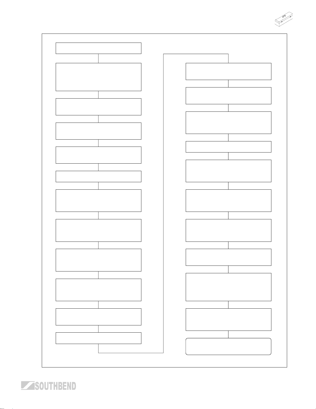
A
Oven Thermostat Calibration
Check that the thermostat bulb is
in the bracket and centered.
Check that the blower baffle is
bolted in place. C.O. base only.
Check that the oven bottom is
in place.
Raise the kick panel slightly and
rotate forward.
Suspend a thermocouple on the
center of the oven rack in the
center of the oven.
Remove the knob, bezel and valve
cover panel.
Set the oven knob to the midpoint
between the two lines just after the
OFF position.
This is the bypass setting.
Check that there is a ¼ in. flame
at each port.
If the flame is not correct remove
the knob and bezel.
There is a slotted screw below the
stem on the thermostat valve (see
page 26).
Turn the screw counter clockwise
to establish or increase the flame.
Put the bezel and knob on the oven
thermostat.
Set the oven thermostat to 400°F.
Check the burner for poor
operation through the hole behind
the kick plate while the oven is
heating.
See flowchart on page 32 for
burner troubleshooting.
fter oven temperature is stabilized
observe that the flame has
decreased.
Turn the screw clockwise to
decrease the flame.
If no flame is established put a
flame to the mixer face at the
burner shutter to check for gas
flow.
If gas is flowing turn the bypass
screw until flame is set to
specifications.
If no flame can be established at
the bypass setting replace the
thermostat.
Continues on Next Page
ADJUSTMENTS
OPERATOR’S MANUAL 1182298 REV 3 PAGE 27
Page 28

ADJUSTMENTS MODEL 300 RESTAURANT RANGES
p
Continued from Previous Page
The bypass setting must be
calibrated before calibrating the
oven thermostat.
Remove the oven knob and push
out the silver center from the rear
of the knob and reinstall the knob
on the thermostat.
Set the knob indicator to 400°F
and allow the oven to reheat.
Allow the temperature to stabilize.
The temperature is stable when the
change is no more than 5°F.
If the change is greater than 5°F
return to the bypass calibration.
While holding the knob at the
400°F setting, push the screw in,
and turn it in the direction indicated
to calibrate the tem
Allow the temperature to stabilize.
Repeat this procedure until the
temperature stabilizes to +/-10°F
of the setting.
If the temperature cannot be set to
within +/-10°F replace the
thermostat and retest.
Reinstall the silver cover in
the knob center.
erature.
The temperature should be within
+/- 10°F of the setting.
To calibrate the temperature go to
the center of the thermostat.
Scrape the paint seal off of the
screw.
ADJUSTMENTS
NOTE! There are arrows around
the screw indicating (H) to increase
and (L) to decrease the
temperature.
NOTE! Only turn this screw by
small increments.
PAGE 28 OPERATOR’S MANUAL 1182298 REV 3
Page 29

MODEL 300 RESTAURANT RANGES ADJUSTMENTS
THERMOSTATIC GRIDDLE BY-PASS FLAME LEVEL
When the griddle reaches the temperature at which the dial is set, the control cuts down the flow of gas to
the amount required to keep the griddle at that temperature. Always, however, the control must by-pass
enough gas to keep the entire burner lighted. To maintain this minimum flame, the by-pass must be set
carefully and accurately, as follows (see illustration on page 30):
1. Light the burner, then turn dial “FULL ON.”
2. After 5 minutes, turn dial clockwise to point slightly beyond first mark on dial.
3. Remove dial and bezel.
4. With a screwdriver, turn by-pass Adjustor (counterclockwise to increase the flame, clockwise to decrease
it) until there is a minimum flame over the entire burner.
5. Replace bezel and dial, turning the dial clockwise until it locks in the “Off” position.
THERMOSTATIC GRIDDLE THERMOSTAT CALIBRATION
The griddle temperature control is carefully calibrated at the factory—that is, it is so adjusted that dial
settings match actual temperatures. Field recalibration is seldom necessary, and should not be resorted to
unless considerable experience with cooking results definitely proves that the control is not maintaining the
temperatures to which the dial is set.
Recalibration should not be undertaken, however, until the griddle by-pass flame has been adjusted (see
previous subsection).
To check temperatures when recalibrating, use a test instrument with a DISC type thermocouple for surface
temperature checking. Drop a couple of drops of oil on griddle surface plate and place thermocouple disc flat
into the oil.
Proceed as follows (see illustration on page 30):
1. Remove dial and push out metal insert.
2. Replace dial, turn to 350 mark, and light burner.
3. After burner has been on about 15 minutes check temperature.
4. Continue to check temperature, at 5-minute intervals, until two successive readings are within 5 degrees
of each other.
The control should be recalibrated if your reading is not within 20 degrees of the dial setting (350 degrees). If
calibration is required, the additional steps to be taken are these:
5. Hold dial firmly, insert screwdriver through center of dial, and push calibration stem inward. DO NOT
TURN THIS STEM.
6. While holding calibration stem in firmly with screwdriver, turn dial until it is set at the actual oven
temperature as shown by your test instrument. Release pressure on calibration stem. Replace dial insert.
7. Set dial at 400 mark. Check temperature again, as instructed in (3) and (4). If the temperature is not
within 20 degrees of the dial setting (400 degrees), it means that the sensing element is inoperative and
the control should be replaced.
ADJUSTMENTS
OPERATOR’S MANUAL 1182298 REV 3 PAGE 29
Page 30

ADJUSTMENTS MODEL 300 RESTAURANT RANGES
CONVERSION FROM ONE TYPE OF GAS TO ANOTHER
Each appliance is shipped gas-specific either for use with natural gas or for use with LP gas (propane). To
convert an appliance from one type of gas to another, do the following:
1. Refer to service procedures to access all burner orifices.
2. Refer to instructions included with conversion kit.
ADJUSTMENTS
3. F2 3480292. s
the proce
Page 31

MODEL 300 RESTAURANT RANGES TROUBLESHOOTING
TROUBLESHOOTING
TROUBLESHOOTING RANGE TOP BURNERS
Consult the following table and the flowchart that begins on the following page.
Problem Look for -
All burners and pilots in unit will not turn on – Main gas supply to unit is “OFF.”
All burners produce excessive carbon deposits – Incorrect gas type supplied to unit.
– Incorrect supply pressure.
Only some burners in a unit produce excessive carbon
deposits
Only some pilots produce excessive carbon deposits – Pilot gas not adjusted properly.
Top burner (not oven) will not come on – Manual valve for top burner in “OFF” position.
Top section pilot will not stay ignited – Pilot gas not adjusted properly.
– Incorrect orifices.
– Primary air not adjusted properly.
– Incorrect pilot orifice.
– Pilot out.
– Clogged orifice.
– Draft condition.
– Improper ventilation system.
– Air in gas line.
TROUBLESHOOTING
OPERATOR’S MANUAL 1182298 REV 3 PAGE 31
Page 32

TROUBLESHOOTING MODEL 300 RESTAURANT RANGES
RANGE TOP BURNER
TROUBLESHOOTING
Common checks for all top
configurations.
Check that the burners are set level
in the support brackets.
Check that the burners are clean
and all ports are clear.
Remove each burner and check
that the venturi is clean and free of
buildup and debris.
With each burner removed check
that the orifice size is correct and
clean and free of buildup and
debris.
Remove the knobs and carefully
lower the top valve cover panel.
CAUTION! Wiring attached behind
panel on C.O. base models.
NOTE: Griddle Tops
NOTE: Griddles and Hot Tops
must be raised and secured or
removed.
CAUTION! Before raising or
removing Griddle Tops.
Remove the knobs and carefully
lower the top valve cover panel.
CAUTION! Wiring attached behind
panel.
Pull the Griddle thermostat
bulbs out of the tubes.
Light all burners on the range.
NOTE: Leave the oven door open.
Observe the inlet pressure.
Check that each burner valve and
orifice is in alignment with the
burner.
Shut off the main gas supply.
Install a pressure tap in the main
gas line before the range pressure
regulator and install a manometer.
Turn on the main gas supply.
TROUBLESHOOTING
PAGE 32 OPERATOR’S MANUAL 1182298 REV 3
Re-light all pilots.
Inlet pressures for gases are:
Natural = 3.5" to 5" water column
Propane = 10" to 11" water column
If the inlet pressure is low, all
equipment on the main gas line
should be lit and the pressure
adjusted.
Shut off the range burners and
main gas and remove the pressure
Continues on next page.
tap.
Page 33
MODEL 300 RESTAURANT RANGES TROUBLESHOOTING
Continued from Previous Page
With the gas supply shut off to the
range install a pressure tap on the
manifold in the plugged tap
provided.
Install a manometer on the
pressure tap.
Turn on the gas supply to the
range.
Re-light the pilots and turn on all
the burners.
Observe the manifold pressure.
Manifold pressures are:
Natural gas = 4" water column
Propane gas = 10" water column
Install the grates or griddle/hot
tops.
Install the thermostat bulbs into
griddle tops.
Be sure the capillary tubes are
away from burners, flames and
excessive heat.
Test each burner.
Each burner should have a steady
blue flame on each port of the
burner.
Propane burners may have a small
amount of yellow tipping. This is
normal.
If the pressure is low remove the
cap from the pressure regulator on
the back of the range.
Clockwise increases the pressure
and counter clockwise decreases
If the flame is rising up off of the
ports adjust the burner shutter
closed.
If the flame is long and yellow
adjust the burner shutter open.
the pressure.
NOTE: Griddle and Hot Top
Shut off the range burners and
main gas and remove the pressure
tap.
Replace the pressure tap plug in
the manifold.
burners may be long and float
when cold. Allow the top to heat
before making burner adjustments.
Propane burners may have a slight
popping noise when turned off.
TROUBLESHOOTING
This is normal.
Re-light the pilots.
Reinstall the top valve cover panel
and knobs.
OPERATOR’S MANUAL 1182298 REV 3 PAGE 33
Page 34

TROUBLESHOOTING MODEL 300 RESTAURANT RANGES
TROUBLESHOOTING BASE OVEN
! CAUTION
Proper and efficient operation of oven is dependent on correct installation and function of
components. Always verify that components are in place and functioning as intended.
Consult the following table and the flowchart that begins on the following page.
Problem Look for -
Oven will not come on. – Oven pilot is out.
Oven pilot will not stay ignited – Pilot gas not adjusted properly.
– Bad thermocouple. (Applies to units with D suffix only)
– Bad thermocouple connections at safety valve. (Applies to
units with D suffix only)
– Bad safety.
– Clogged orifice.
– Draft condition.
– Improper ventilation system.
– Air in gas line.
TROUBLESHOOTING
PAGE 34 OPERATOR’S MANUAL 1182298 REV 3
Page 35

MODEL 300 RESTAURANT RANGES TROUBLESHOOTING
OPERATOR’S MANUAL 1182298 REV 3 PAGE 35
TROUBLESHOOTING
Page 36

TROUBLESHOOTING MODEL 300 RESTAURANT RANGES
TROUBLESHOOTING THERMOSTATIC GRIDDLE
THERMOSTATIC GRIDDLE
TROUBLESHOOTING
If the flame is not correct remove
Remove the knobs and valve
cover panel.
the knobs and bezel. See
illustration on page 30.
CAUTION! WIRING BEHIND THE
PANEL.
Be sure the thermostat bulbs are
pushed completely into the tubes
under the griddle.
Put the bezels and knobs on the
griddle thermostats.
Set the griddle thermostats
to 300°F.
Observe the burners while heating
griddle for poor operation.
Refer to flowchart on page 32 for
burner troubleshooting.
After griddle has heated for
approximately 20 minutes, observe
that the flame has decreased in
height.
There is a slotted screw below the
stem on the thermostat valve.
Turn the screw counter clockwise
to establish or increase the flame.
Turn the screw clockwise to
decrease the flame.
If no flame is established put a
soap and water mix to the orifice of
the burner to check for gas flow.
If gas is flowing turn the bypass
screw until flame is set to
specifications.
If no flame is established at the
bypass setting replace the
thermostat.
Remove the knobs and bezel and
install the valve cover panel.
Set the griddle knobs to the
midpoint between the two lines just
after the OFF position.
This is the bypass setting.
TROUBLESHOOTING
PAGE 36 OPERATOR’S MANUAL 1182298 REV 3
Check that there is a ¼ in. flame at
each port.
Reinstall the bezels and push out
the silver center of the knob from
the rear of the knob and reinstall.
Set the temperature to 300°F and
allow the griddle to reheat.
Continues on Next Page
Page 37

MODEL 300 RESTAURANT RANGES TROUBLESHOOTING
Record the temperatures
Reinstall the knobs, bezels and
valve cover panel.
NOTE! There are arrows around
the screw indicating (H) to increase
and (L) to decrease the
temperature.
OPERATOR’S MANUAL 1182298 REV 3 PAGE 37
TROUBLESHOOTING
Page 38

TROUBLESHOOTING MODEL 300 RESTAURANT RANGES
TROUBLESHOOTING CONVECTION OVEN BLOWER MOTOR
! WARNING
Before attempting to service or replace any electrical component, make sure power source has been
disconnected.
! CAUTION
When changing motor or servicing unit, always verify that blower wheel rotation is clockwise when
looking into the oven cavity.
The motor is serviceable from the front of the unit through the oven cavity. Remove the back lining.
Disconnect the motor mount plate by removing the eight hex nuts that secure it to the oven interior back. Pull
the mount plate, with motor attached, into the oven.
Motor lubrication information can be found on permanent label located on motor.
If the blower does not run at all, consult the flowchart that begins on the next page. If the blower runs
intermittently, consult the flowchart on the third page following.
The appropriate wiring diagram for the oven can be found on the rear of the oven (as well as at the end of
this section of this manual).
TROUBLESHOOTING
PAGE 38 OPERATOR’S MANUAL 1182298 REV 3
Page 39

MODEL 300 RESTAURANT RANGES TROUBLESHOOTING
CONVECTION OVEN BLOWER
DOES NOT RUN
Move a DVM probe to the center terminal of the
REMOVE THE MAIN POWER
SOURCE. UNPLUG OR
DISCONNECT CIRCUIT
BREAKER.
Check the voltage specified by the Serial Plate
located behind the oven valve cover panel.
switch wires 1 and 2.
Remove the control knobs from the
range.
CAUTION! WIRING BEHIND THE
PANEL OF THE NEXT STEP.
Remove the upper valve panel
cover screws and tilt the panel
forward to expose the back of
blower switch.
Remove the protective cover from
over the switch.
Check that the wires and terminals
are secure on the switch.
Refer to schematic P/N’s:
1181101 for 120V,
1181102 for 208/240V.
Place a DVM on the end terminals
of the blower switch wires 1 and 3.
Connect the main power supply.
Is the voltage
as specified?
Reinstall the switch
cover and valve
panel.
Turn on the power
switch.
Open the oven door.
If the blower runs,
the Door Switch is
wired wrong.
Disconnect the main
power supply.
NoYes
Disconnect the main
power supply.
Check the facility's
power supplies.
Reinstall the switch
cover and valve
panel.
Connect the main
power supply.
Test oven.
Place switch in on position.
No
Continuity?
Yes
Open the kick panel by raising it
and tilting the top outward.
Check that one wire is connected
to the (common), 90° bottom
terminal of the switch.
Replace the switch.
Move the other wire to the lower
Reinstall the switch cover and
leg (N.O.) on the side of the switch.
valve panel.
Continues on following page.
Test blower.
OPERATOR’S MANUAL 1182298 REV 3 PAGE 39
TROUBLESHOOTING
Page 40

TROUBLESHOOTING MODEL 300 RESTAURANT RANGES
Continued From
Prev age
ious P
Go to the motor and remove the wire terminal cover.
CAUTION!
Be sure the main power is
disconnected.
Place a DVM on the door
switch terminals with the
connected wires.
Press the switch actuator
lever.
Continuity?
Yes
Replace the switch.
Test oven.
Close the oven door.
No
Check that the red wire is capped off.
Remove the wire nuts from the black and white wires.
Check that the wires are twisted together securely.
Check that the common wire is connected to the motor
black wire.
Check that the neutral wire is connected to the white wire.
Place a DVM on the black and the white wire.
Connect the main power supply.
Turn on the blower switch.
Power?
No Yes
No
Loosen the 2 screws on
the door switch bracket
and adjust it to the door
ge to actuate the switchin
Connect the main power
Reinstall the kick panel.
TROUBLESHOOTING
Continuity?
supply.
Test oven.
Yes
h.
Disconnect the main
power supply.
Remove the wire nuts
from the red, white, and
black wires.
Check for approx. 1.9
ohms across the white
and black wire, then the
white and red.
Replace the motor if
different.
Connect the main power
supply.
Test oven.
Check all wiring for loose
terminals or breaks.
Check Power Switch
and Door Switch per
th .
e instructions
PAGE 40 OPERATOR’S MANUAL 1182298 REV 3
Page 41

MODEL 300 RESTAURANT RANGES TROUBLESHOOTING
OPERATOR’S MANUAL 1182298 REV 3 PAGE 41
TROUBLESHOOTING
Page 42

TROUBLESHOOTING MODEL 300 RESTAURANT RANGES
Electrical Schematic for 120 Volt Ranges
TROUBLESHOOTING
PAGE 42 OPERATOR’S MANUAL 1182298 REV 3
Page 43

MODEL 300 RESTAURANT RANGES TROUBLESHOOTING
Electrical Schematic for 208-230 Volt Ranges
OPERATOR’S MANUAL 1182298 REV 3 PAGE 43
TROUBLESHOOTING
Page 44

PARTS MODEL 300 RESTAURANT RANGES
PARTS
! WARNING
INSTALLATION OF OTHER THAN GENUINE SOUTHBEND PARTS WILL VOID THE WARRANTY
ON THIS EQUIPMENT.
The serial plate is located in the compartment below the oven on the right side. When ordering parts, please
supply the Model Number, Serial Number, Part Number, and Description; plus Finish, Type of Gas, and
Electrical Characteristics, as applicable.
For parts not listed, consult a Southbend Authorized Parts Distributor or Southbend Authorized Service
Agency. If necessary, please consult Southbend Parts Department for assistance.
Index of Restaurant Range Parts Diagrams
PARTS
PAGE 44 OPERATOR’S MANUAL 1182298 REV 3
Page 45

MODEL 300 RESTAURANT RANGES PARTS
Shelf and Flue Riser Parts for Models 324 and 336
Page 46

PARTS MODEL 300 RESTAURANT RANGES
Shelf and Flue Riser Parts for Models 348 and 360
1
2
Key Part Number Description
1 1180845 Shelf weld assembly, 60"
* 1181140 Shelf weld assembly, 48"
2 1180768 Flue riser assembly, 22.5" x 60"
* 1181152 Flue riser assembly, 10" x 60"
* 1181136 Flue riser assembly, 22.5" x 48"
* 1181153 Flue riser assembly, 10" x 48"
* not shown on drawing.
PARTS
PAGE 46 OPERATOR’S MANUAL 1182298 REV 3
Page 47

MODEL 300 RESTAURANT RANGES PARTS
Valve Panel, Base Panel, and Drip Pan Parts
Page 48

PARTS MODEL 300 RESTAURANT RANGES
Leg Parts
3
2
1
4
Key Part Number Description
1 1146201 1/4 x 20 x 3/4 Hex Head
2 1146500 1/4 Lock Washer
3 1172650 Leg Pad (3/4 x 10 hole)
4 1178205 Leg Package (set of 4 legs, not including bolts, leg pads, or lock washers)
* 1174262 Earthquake Legs SS (set of 4)
* not shown on drawing.
Caster Parts
3
2
1
4
Key Part Number Description
1 1146201 1/4 x 20 x 3/4 Hex Head
2 1146500 1/4 Lock Washer
3 1172650 Leg Pad (3/4 x 10 hole)
4 1174265 Caster Package (two casters with brake and two without brake; does not include bolts, lock washers, or leg pads)
* not shown on drawing.
PARTS
PAGE 48 OPERATOR’S MANUAL 1182298 REV 3
Page 49

MODEL 300 RESTAURANTj0.000809.88.2443 748.26(300 R)Tj0.000TNTNTN13.5870.00016.006.00251.88.2332 748.26 PODEL
Page 50

PARTS MODEL 300 RESTAURANT RANGES
24" and 36" Griddle Parts
See drawing on following page.
Key Part Number Description
1 1178204 Griddle Knob
2 1178202 Valve Body Only
3 1042980 Griddle Bar Burner
4 1134810 Burner Support
5 1181212 Griddle Assembly, 24", Left (for units manufactured before October 13, 2003)
1181213 Griddle Assembly, 24", Right (for units manufactured before October 13, 2003)
1181214 Griddle Assembly, 24", Left, Thermostatic (for units manufactured before October 13, 2003)
1181215 Griddle Assembly, 24", Right, Thermostatic (for units manufactured before October 13, 2003)
1181216 Griddle Assembly, 36", Left (for units manufactured before October 13, 2003)
1181217 Griddle Assembly, 36", Right (for units manufactured before October 13, 2003)
1181218 Griddle Assembly, 36", Left, Thermostatic (for units manufactured before October 13, 2003)
1181219 Griddle Assembly, 36", Right, Thermostatic (for units manufactured before October 13, 2003)
5 1186232 Griddle Assembly, 24", Left (for units manufactured after October 13, 2003)
1186233 Griddle Assembly, 24", Right (for units manufactured after October 13, 2003)
1186234 Griddle Assembly, 24", Left, Thermostatic (for units manufactured after October 13, 2003)
1186235 Griddle Assembly, 24", Right, Thermostatic (for units manufactured after October 13, 2003)
1186236 Griddle Assembly, 36", Left (for units manufactured after October 13, 2003)
1186237 Griddle Assembly, 36", Right (for units manufactured after October 13, 2003)
1186238 Griddle Assembly, 36", Left, Thermostatic (for units manufactured after October 13, 2003)
1186239 Griddle Assembly, 36", Right, Thermostatic (for units manufactured after October 13, 2003)
6 1162828 Griddle Pilot (for 24" griddle)
1162980 Griddle Pilot (for 36" griddle)
7 1146906 90° Elbow
8 P3875 1/8 x 1/4 Straight Fitting
9 1099111 1/4 cc Nut
10 1162236 Pilot Tube
11 1099111 1/4 cc Nut
12 1099112 1/4 Ferrule
13 1163844 Pilot Adj. Valve
14 1179997 Thermostat Knob **
15 1174709 Thermostat Only **
16 1147201 Brass Tee **
17 1174713 Gas Supply Tube **
18 1008748 Orifice NAT **
1008755 Orifice LP **
19 1166150 Brass Elbow **
20 1174714 Gas Supply Tube **
* 1008748 Griddle Orifice NAT
* 1008756 Griddle Orifice LP
* 1181221 Grease Drawer
* not shown on drawing.
** used on thermostatically controlled griddles (indicated by a “T” prefix)
PARTS
PAGE 50 OPERATOR’S MANUAL 1182298 REV 3
Page 51

MODEL 300 RESTAURANT RANGES PARTS
24" and 36" Griddle Parts
See parts list on previous page.
Optional Thermostatic Griddle
Controls for 36" Griddle
14
151819 20
5
4
13
12
11
10
Optional Thermostatic Griddle
Control for 24" Griddle
14
3
6
2
8
7
6
9
1
5
4
18
15
OPERATOR’S MANUAL 1182298 REV 3 PAGE 51
16
17
1 2
6
3
PARTS
Page 52

PARTS MODEL 300 RESTAURANT RANGES
12" Griddle Parts
12
11
Key Part Number Description
1 1178204 Knob, Control
2 1178202 Valve, Hi-Off
3 1042980 Burner, Bar Assembly
4 1134810 Burner Support
5 1162807 Lighter Pipe Weld Assembly
6 1146906 Elbow 90 Deg, Street
7 P3875 Str. Fitting 1/8 THD 1/4 Less Nut/Sleeve
8 1099112 Ferrule, 1/4
9 1099111 Nut, 1/4 CC
10 1162236 Pilot Tube (7.500)
11 1099002 Pilot Adjustment Valve
1181723 Griddle Weld Assembly 12" Left (for units manufactured before October 13, 2003) 12
1186231 Griddle Weld Assembly 12" Left (for units manufactured
* 1181221 Grease Drawer Assembly
* 1008748 Orifice NAT Gas
* 1008756 Orifice LP Gas
* not shown on drawing.
7
9
10
1
6
8
5
4
3
2
after October 13, 2003)
PARTS
PAGE 52 OPERATOR’S MANUAL 1182298 REV 3
Page 53

MODEL 300 RESTAURANT RANGES PARTS
Hot Top Parts
12
13
4
3
2
1
5
7
9
6
8
11
10
Key Part Number Description
1 1178204 Knob Control
2 1178202 Gas Valve
3 1008751 Hood Orifice NAT
1008757 Hood Orifice LP
4 1022994 Hot Top Burner
5 1099002 Filter & Valve
6 1099101 1/8 Reduction Ferrule
7 1099100 1/8 cc Nut
8 3346 Pilot Tube
9 1160410 Pilot Assembly
10 3435 Pilot Bracket
11 3448 Burner Support
12 1170417 Aeration Box
13 1112299 Top Plate Assembly
OPERATOR’S MANUAL 1182298 REV 3 PAGE 53
PARTS
Page 54

PARTS MODEL 300 RESTAURANT RANGES
Raised-Griddle Broiler Parts
See drawing on following page.
Key Part Number Description
1 1161636 Broiler Dirt Tray
2 1173555 Broiler Rack Pan
3 1173554 Broiler Rack
4 1173556 Broiler Rack Support
5 1133999 Griddle Pilot
6 P3875 1/8 x 1/4 Straight Fitting
7 1099112 1/4 Ferrule
8 1099111 1/4 cc Nut
9 1162935 Gas Supply Tube
10 1099111 1/4 Nut
11 1099112 1/4 Ferrule
12 1163844 Pilot Adj. Valve
13 1073495 Broiler Valve Handle
14 1146304 Screw # 10 x 1/2 Phil
15 1178202 Broiler Valve
16 P3111 Ceramic (side) 3-1/2 x 7-1/2 x 1/2
17 P3112 Ceramic (center) 6-9/16 x 7-1/2 x 1/2
18 1162925 Broiler Burner (center)
19 1162924 Broiler Burner (side)
20 1030200 Burner Rest Bracket
21 3240 Rear Plate Rest Broiler
22 1009199 Griddle Plate
23 1042980 Griddle Burner
24 1162334 Griddle Pilot
* 1008749 Broiler Burner Orifice RT & LT NAT
* 1008757 Broiler Burner Orifice RT & LT LP
* 1008753 Broiler Burner Orifice Center NAT
* 1008765 Broiler Burner Orifice Center LP
* not shown on drawing
PARTS
PAGE 54 OPERATOR’S MANUAL 1182298 REV 3
Page 55

MODEL 300 RESTAURANT RANGES PARTS
Raised-Griddle Broiler Parts
See parts list on previous page.
23
24
22
6
7
8
13
12
10
4
3
2
11
15
14
16
18
17
9
5
21
20
19
1
OPERATOR’S MANUAL 1182298 REV 3 PAGE 55
REAR VIEW
PARTS
Page 56

PARTS MODEL 300 RESTAURANT RANGES
Convection Oven Parts
See drawing on following page.
Key Part Number Description
1 1180783 Panel, Kick
2 1181376 Logo Plate
3 1180861 Door Hinge
4 1024196 Door Assembly (Full Oven)
1179072 Door Assembly (Space Saver Oven)
5 1179950 Door Handle (Full Oven)
1179952 Door Handle (Space Saver Oven)
* P1089 Spring, Door (Full Oven)
1179030 Spring, Door (Space Saver Oven)
6 6660 Clip, Rack Support
7 1180528 Rack Guide
8 1177581 Blower Wheel Assembly
9 1180821 Pocket Weld Assembly
10 1179710 Spacer, Blower
11 1177452 Motor, 1/3 HP, 115 Volt
1179688 Motor, 1/3 HP, 208/240 Volt
12 1181117 Bracket, Door Switch
13 1177567 Switch, Door
14 1180859 Quadrant Assembly
15 1180834 Oven Baffle Co.
16 1180841 Bracket, Oven Baffle
17 1180776 Oven Bottom (Full Oven)
1180853 Oven Bottom (Space Saver Oven)
18 1164278 SA Burner (Natural Gas)
1164279 SA Burner (LP Gas)
19 1164037 Oven Safety Valve
20 1008736 Hood Orifice #36 (Natural Gas)
1008752 Hood Orifice #52 (LP Gas)
21 1180873 Pilot Tube
22 1163868 Thermocouple
23 1180830 Bracket, Oven Safety
* not shown on drawing
PARTS
PAGE 56 OPERATOR’S MANUAL 1182298 REV 3
Page 57

MODEL 300 RESTAURANT RANGES PARTS
Convection Oven Parts
See parts list on previous page.
14
13
12
11
10
9
8
15
7
6
5
4
3
2
1
17
16
23
18
19
20
21
22
OPERATOR’S MANUAL 1182298 REV 3 PAGE 57
PARTS
Page 58

PARTS MODEL 300 RESTAURANT RANGES
Standard Oven Parts
See drawing on following page.
Key Part Number Description
1 1024196 Door Assembly (Full Oven)
1179072 Door Assembly (Space Saver Oven)
2 1180861 Door Hinge
* P1089 Spring, Door (Full Oven)
1179030 Spring, Door (Space Saver Oven)
3 1180776 Oven Bottom (Full Oven)
1180853 Oven Bottom (Space Saver Oven)
4 1173547 Rod, Oven
5 1180859 Quadrant Assembly
6 1164278 SA Burner (Natural Gas)
1164279 SA Burner (LP Gas)
7 1179998 Dial Knob, Oven
8 1179999 Bezel
9 B940000201 Thermostat
10 1164037 Oven Safety Valve
11 1008736 Hood Orifice #36 (Natural Gas)
1008752 Hood Orifice #52 (LP Gas)
12 1180873 Pilot Tube
13 1163868 Thermocouple
14 1180830 Bracket, Oven Safety
* not shown on drawing
PARTS
PAGE 58 OPERATOR’S MANUAL 1182298 REV 3
Page 59

MODEL 300 RESTAURANT RANGES PARTS
PARTS
Page 60

MODEL 300 RESTAURANT RANGES
Notes:
PAGE 60 OPERATOR’S MANUAL 1182298 REV 3
Page 61

MODEL 300 RESTAURANT RANGES
Notes:
OPERATOR’S MANUAL 1182298 REV 3 PAGE 61
Page 62

MODEL 300 RESTAURANT RANGES
Notes:
PAGE 62 OPERATOR’S MANUAL 1182298 REV 3
Page 63

MODEL 300 RESTAURANT RANGES
Notes:
OPERATOR’S MANUAL 1182298 REV 3 PAGE 63
Page 64

MODEL 300 RESTAURANT RANGES
SELECT
RESTAURANT RANGES
A product with the Southbend name incorporates the best in durability and low maintenance. We
all recognize, however, that replacement parts and occasional professional service may be
necessary to extend the useful life of this unit. When service is needed, contact a Southbend
Authorized Service Agency, or your dealer. To avoid confusion, always refer to the model number,
serial number, and type of your unit.
Southbend
1100 Old Honeycutt Road, Fuquay-Varina, NC 27526
(919) 552-9161 • FAX (919) 552-9798
PAGE 64 OPERATOR’S MANUAL 1182298 REV 3
 Loading...