

Page 1

$6.00
southbend
A MIDDLEBY COMPANY
OWNER'S MANUAL
INSTALLATION
USER'S GUIDE
SERVICE
PARTS
IMPORTANT
FOR FUTURE REFERENCE
Please complete this
information and retain this
manual for the life of the
equipment.
MODEL #__________________
SERIAL #__________________
DATE PURCHASED__________
COUNTER TOP
CONVECTION STEAMER
MODELS: 2001 / DUAL POWER
SINGLE POWER SOURCE UNITS
These instructions should be read thoroughly before attempting installation. Installation and
Start Up should be performed by a qualified service technician. The Manufacturer,
Southbend (Head Office: 1100 Old Honeycutt Rd., Fuquay-Varina, North Carolina 27526),
informs you that unless the installation instructions for the above described Southbend
product are followed and performed by a qualified service technician, (a person experienced
in and knowledgeable concerning the installation of commercial gas and/or electrical cooking
equipment) then the terms and conditions of the Manufacturer's Limited Warranty will be
rendered void and no warranty of any kind shall apply.
If the equipment has been changed, altered, modified or repaired by other than a qualified
service technician during or after the 12-month limited warranty period, then the
manufacturer shall not be liable for any incidental or consequential damages to any person
or to any property which may result from the use of the equipment thereafter. Some States
do not allow the exclusion or limitation of incidental or consequential damages, so the above
limitation or exclusion thereto may not apply to you.
In the event you have any questions concerning the installation, use, care, or service of the
product, write Customer Service Department, Southbend, 1100 Old Honeycutt Rd., Fuquay Varina, North Carolina 27526.
WARNING: Improper installation, adjustment, alteration, service or maintenance can cause
property damage, injury or death. Read the installation, operating and maintenance instructions
thoroughly before installing or servicing this equipment.
COUNTER TOP
CONVECTION STEAMER
(Manual Section CS)
Page 2
1100 Old Honeycutt Road
Congratulations! You have just purchased one of the finest pieces of heavy-duty, commercial cooking equipment on the market
today.
You will find that your new equipment, like all Southbend equipment, has been designed and manufactured to some of the
toughest standards in the industry — those of Southbend. Each piece of Southbend equipment has been carefully engineered and
designs have been verified through laboratory tests and field installations in some of the more strenuous commercial cooking
applications. With proper care and field maintenance, you will experience years of reliable, trouble -free operation from your
Southbend equipment. To get the best results, it's important that you read this manual carefully.
TABLE OF CONTENTS:
SECTION ONE - INSTALLATION
Specifications ......................................…………...... 1
Installation .....................................……………........ 2
Performance Check………………………………… 5
SECTION TWO - USER'S GUIDE
Warranty.........................................…………….......
Operation....................................……………............
Cooking Hints.........................…………........... . ....
Maintenance............................…………........... . ....
SECTION THREE - SERVICE
1
2
3
7
Adjustments ..................................……............ .... .. 1
Troubleshooting .............................…....................... 5
Schematic Drawings……………………………….. 7
SECTION FOUR - PARTS
Parts List.......................................……..................... 1
RETAIN THIS MANUAL FOR FUTURE REFERENCE.
INTENDED FOR COMMERCIAL USE ONLY. NOT FOR HOUSEHOLD USE.
WARNING – WARRANTY WILL BE VOID IF
A. SERVICE WORK IS PERFORMED BY OTHER THAN A QUALIFIED TECHNICIAN
B. OTHER THAN GENUINE SOUTHBEND REPLACEMENT PARTS ARE INSTALLED.
FOR YOUR SAFETY
DO NOT STORE OR USE GASOLINE OR OTHER FLAMMABLE VAPORS
AND LIQUIDS IN THE VICINITY OF THIS OR ANY OTHER APPLIANCE.
KEEP AREA AROUND APPLIANCES FREE AND CLEAR FROM COMBUSTIBLES.
IN THE EVENT A GAS ODOR IS DETECTED. SHUT DOWN EQUIPMENT AT THE MAIN
SHUTOFF VALVE AND CONTACT THE LOCAL GAS COMPANY OR GAS SUPPLIER FOR
SERVICE.
southbend
A MIDDLEBY COMPANY
Fuquay, NC 27526
(919) 552-9161
FAX (919) 552-9798
(800) 348-2558
Page 3

COUNTER TOP
CONVECTION STEAMER
USER'S GUIDE
LIMITED WARRANTY
Southbend warrants that the equipment, as supplied by the factory to the original purchasers, is free from defects in materials
and workmanship. Should any part thereof become defective as a result of normal use within the period and limits defined
below, then at the option of Southbend such parts will be repaired or replaced by Southbend or its Authorized Service Agency.
This warranty is subject to the following conditions:
If upon inspection by Southbend or its Authorized Service Agency it is determined that this equipment has not been used in an
appropriate manner, has been modified, has not been properly maintained, or has been subject to misuse or misapplication,
neglect, abuse, accident, damage during transit or delivery, fire, "flood, riot or Act of God, then this warranty shall be void.
Specifically excluded under this warranty are claims relating to installation; examples are improper utility connections and
improper utilities supply. Claims relating to normal care and maintenance are also excluded; examples are calibration of
controls, and adjustments to pilots and burners.
Equipment failure caused by inadequate water quality is not covered under warranty. WATER QUALITY must not exceed the
following limits: Total Dissolved Solids (TDS) - 60 PPM (Parts Per Million). Hardness - 2 Grains or 35 PPM, PH Factor
- 7.0 to 7.5. Water pressure 30 PSI minimum, 60 PSI maximum. Boiler maintenance is the responsibility of the owner and is not
covered by warranty.
This equipment is intended for commercial use only. Warranty is void if equipment is installed in other than commercial
application.
Repairs under this warranty are to be performed only by a Southbend Authorized Service Agency. Southbend can not be
responsible for charges incurred from other than Authorized Southbend Agencies. THIS WARRANTY MUST BE SHOWN TO AN
AUTHORIZED SERVICE AGENCY WHEN REQUESTING IN-WARRANTY SERVICE WORK. THE AUTHORIZED SERVICE
AGENCY MAY AT HIS OPTION REQUIRE PROOF OF PURCHASE. This warranty does not cover services performed at
overtime or premium labor rates nor does Southbend assume any liability for extended delays in replacing or repairing any items
in the equipment beyond the control of Southbend. "Southbend shall not be liable for consequential or special damages of any
nature that may arise in connection with such product or part." Should service be required at times which normally involve
overtime or premium labor rates, the owner shall be charged for the difference between normal service rates and such premium
rates. In all circumstances, a maximum of one hundred miles in travel and two and one half hours (25) travel time shall be
allowable. In all cases the closest Southbend Authorized Agency must be used. The actual warranty time periods and exceptions
are as follows:
This warranty only covers product shipped into the 48 contiguous United States and Hawaii, one year labor, one year parts
effective from the date of original purchase. There will be no labor coverage for equipment located on any island not connected
by roadway to the mainland. Exceptions to standard warranty, effective within above limitations:
Glass Windows, Door Gaskets, Rubber Seals, Light Bulbs, Ceramic Bricks,
Sight Glasses, Cathodic Descalers or Anodes ..…......………………………………………...................... 90 days material and labor
Stainless Steel Fry Pot.....................…………….…………………... .4 years extended material warranty on fry pot only — no labor
Stainless Steel Open Top Burners..………….………………...........4 years extended material warranty on burners only — no labor
Pressure Steam Boiler Shell .......…………………………........ Prorated 4 years extended warranty on boiler shell only — no labor
In all cases parts covered by a five year warranty will be shipped FOB the factory after the first year. Our warranty on all
replacement parts which are replaced in the field by our Authorized Service Agencies will be limited to three months on labor, six
months on materials (parts) effective from the date of installation. See LIMITED WARRANTY
- REPLACEMENT PARTS for conditions and limitations.
If the equipment has been changed, altered, modified or repaired by other than a qualified service technician during
or after the one year limited warranty period, then the manufacturer shall not be liable for any damages to any person
or to any property which may result from the use of the equipment thereafter.
"THE FOREGOING WARRANTY IS IN LIEU OF ANY AND ALL OTHER WARRANTIES EXPRESSED OR IMPLIED
INCLUDING ANY IMPLIED WARRANTY OF MERCHANTABILITY OR FITNESS, AND CONSTITUTES THE ENTIRE
LIABILITY OF SOUTHBEND. IN NO EVENT DOES THE LIMITED WARRANTY EXTEND BEYOND THE DURATION
OF ONE YEAR FROM THE EFFECTIVE DATE OF SAID WARRANTY."
Boiler shells which have not been properly maintained will not be covered by warranty.
COUNTER TOP CONVECTION STEAMER
SECTION TWO — USER'S GUIDE
PAGE 1
Page 4

Litho in U.S.A.
OPERATION
THEORY OF OPERATION:
Compared to other steam cookers with complicated boilers, the Southbend 2001 is a very simple machine. The
bottom, or floor, of the compartment is heated. Water flows onto this heated surface, boils, and turns to steam. A fan
circulates the steam in the compartment when the door is closed. There is no pressure.
All equipment must be installed correctly to insure proper operation and reliable service. Installation instructions
must be followed by a qualified technician.
Before you turn the unit on, be sure that you have: POWER to unit, WATER to unit, and OPEN DRAIN. NOTE:
Your Southbend Convection Steamer must be thoroughly cleaned every day.
CAUTION: DO NOT USE VINEGAR OR ANY CORROSIVE CLEANER. USE ONLY CLEANERS
APPROVED FOR STAINLESS STEEL.
Before starting the unit, review the following:
A. Be sure overflow pipe in back right hand comer of the cooking compartment is in position.
B. Be sure the drain outlet is not blocked in any way. (The Southbend 2001 drain line must be free venting.)
C. Be sure the pan supports and fan guard are well secured.
D. Be sure the drip pan is in proper position with the drain hole located above the drain outlet.
CONTROL INSTRUCTIONS:
1. For manual operation, press right-hand rocker switch to "MANUAL" and select your choice on left-hand rocker
switch, "HI or LO." Red and amber lights on switch turn on when it's "HI" power and amber light only when
it's "LO" power. Unit is now in operation and will be generating steam in a few minutes (approximately 4
minutes from a cold start).
2. For automatic timed operation, press right-hand rocker switch to "AUTOMATIC" and select your choice on
left-hand rocker switch "HI" or "LO." Set timer by positioning knob pointer to desired time. When time elapses,
buzzer will sound. Buzzer may be shut off by moving selector switch to "MANUAL," shutting unit off,
resetting to a new time, or turning knob counter clock-wise past "0" time to Hold/Off position.
3. To restart timer, set to new time marking.
NOTE: For short time settings (under 20 minutes) first turn knob past "30" setting then back to desired time.
INSTRUCTIONS FOR TURNING OFF BUZZER:
The Southbend Steamer is supplied with a continuous ring buzzer. This buzzer is activated automatically in the
automatic mode of operation when the cooking cycle is complete. This buzzer can be turned off by:
1. Resetting to a new time.
2. Shut unit off (left hand switch to middle position).
3. Set the right-hand rocker switch to manual.
4. Turn knob full counterclockwise past "0" time to Hold/Off position.
COUNTER TOP CONVECTION STEAMER
SECTION TWO — USER'S GUIDE
PAGE 2
Rev. 12-92
Page 5
MAINTENANCE
Southbend equipment is sturdily constructed of the best quality materials and is designed to provide durable service when treated
with ordinary care. To expect the best performance, your equipment must be maintained in good condition and cleaned daily.
Naturally, the periods for this care and cleaning depend on the amount and degree of usage.
DAILY CLEANING:
Following daily and periodic maintenance procedures will enhance long-life for your equipment. Climatic conditions —
salt air — may require more thorough and frequent cleaning or the life of the equipment could be adversely affected.
As with any cooking utensil, the unit should be thoroughly washed with a mild detergent and warm water every day.
Remove the pan supports, drip pan, fan guard, and overflow pipe. Wash separately.
All water will drain out of the compartment. Clean all interior surfaces, including the fan and heating element with a food equipment
cleansing and de-liming solution. Rinse with clean water.
Return all cleaned parts to the unit to make ready for the next day's operation.
It is advisable to leave door open when the unit is not in use. This allows the unit to dry thoroughly after cleaning and also prolongs
the life of the door seal.
CAUTION: DO NOT USE ANY CORROSIVE CLEANER. USE ONLY CLEANERS APPROVED FOR
STAINLESS STEEL.
STAINLESS STEEL: To remove normal dirt, grease or product residue from stainless steel, use ordinary soap and
water (with or without detergent) applied with a sponge or cloth. Dry thoroughly with a clean cloth. Never use
vinegar or any corrosive cleaner.
To remove grease and food splatter or condensed vapors that have baked on the equipment, apply cleanser to a damp
cloth or sponge and rub cleanser on the metal in the direction of the polishing lines on the metal. Rubbing cleanser as
gently as possible in the direction of the polished lines will not mar the finish of the stainless steel. NEVER RUB
WITH A CIRCULAR MOTION. Soil and burnt deposits which do not respond to the above procedure can usually be
removed by rubbing the surface with SCOTCH-BRTTE scouring pads or STAINLESS scouring pads. DO NOT USE
ORDINARY STEEL WOOL as any particles left on the surface will rust and further spoil the appearance of the
finish. NEVER USE A WIRE BRUSH, STEEL SCOURING PADS (EXCEPT STAINLESS), SCRAPER, FILE OR
OTHER STEEL TOOLS. Surfaces which are marred collect dirt more rapidly and become more difficult to clean.
Marring also increases the possibility of corrosive attack. Refinishing may then be required.
TO REMOVE HEAT TINT: Darkened areas sometimes appear on stainless steel surfaces where the area has been
subjected to excessive heat. These darkened areas are caused by a thickening of the protective surface of the stainless
steel and are not harmful. Heat tint can normally be removed by the foregoing, but tint which does not respond to this
procedure calls for a vigorous scouring in the direction of the polish lines using SCOTCH-BRITE scouring pads or a
STAINLESS scouring pad in combination with a powdered cleanser. Heat tint action may be lessened by not
applying or by reducing heat to equipment during slack periods.
COUNTER TOP CONVECTION STEAMER
SECTION TWO — USER'S GUIDE
PAGE 7
Page 6
SERVICE
COUNTER TOP CONVECTION STEAMER
SECTION THREE – SERVICE
PAGE 7
Page 7
SERVICE
Litho in U.S.A
COUNTER TOP CONVECTION STEAMER
SECTION THREE – SERVICE
PAGE 8
Rev. 12-92
Page 8
southbend
A MIDDLEBY COMPANY
Convection Ovens Ranges Steam Kettles Under Fired Broilers
Cook & Hold Convection Ovens Fryers Tilting Braising Pans Salamander Broilers
Bake & Roast Ovens Special & Custom Equipment Cooker/Mixer Kettles Cheese Melters
Pizza Ovens Convection Steamers Floor Model Broilers Counter Top Broilers & Griddles
Page 9
COUNTER TOP
CONVECTION STEAMER
9161
A MIDDLEBY COMPANY
A product with the Southbend name incorporates the best in durability and low
maintenance. We all recognize however, that replacement parts and occasional
professional service may be necessary to extend the useful life of this unit. When
service is needed, contact a Southbend Authorized Service Agency, or your dealer.
To avoid confusion, always refer to the model number, serial number, and type of
your unit.
southbend
1100 Old Honeycutt Road
Fuq Fuquay-Varina. NC 27526
PART NUMBER 1173012
(919)552FAX (919) 552-9798
(800) 348-2558
Page 10
TO: Southbend Parts & Service Distributors
FROM: Thomas S. Enyeart
Manager, Technical Services
DATE: February 11, 1991 BULLETIN #9105
SUBJECT: Model 2001 and R-1 In Line Water Strainer
Please insert this bulletin in your roaster Southbend manual in Section ST behind the
2001 manual.
A new improved in line water strainer is now being supplied on all Model 2001 and R-1
Convection Steamers. This is a Y type which incorporates a clean out screen.
The Part number is 1173428 and it replaces #PP-629.
Part number 1173428 is on units manufactured January 2, 1991 and after; serial numbers
beginning with 91A and up. Part Number PP-629 was discontinued at the end of December
1990; serial numbers beginning with 90L and before.
Although #1173428 replaces #PP-629, it is not a direct replacement. For the first change
over, you need to use Kit #4440329. After using this kit one time, you then will then just use
#1173428.
A replacement strainer screen is available for this new strainer; Part # 1173429.
Recap:
#PP-629 No longer available - use 173428 or 4440329
1991 List Price
#1173428 In Line Strainer $32.50
#1173429 Replacement Screen $ 3.50
for 1173428
#440329 Replacement Strainer $44.50
Kit to Convert from #PP-629 to 1173428
TE/dy
1100 Old Honeycutt Rd.
Fuquay-Varina, NC 27526
(919) 552-9161
FAX (919) 552-9798
Page 11

TO: Southbend Parts & Service Distributors
FROM: Thomas S. Enyeart
Manager, Technical Services
DATE: June 10, 1991 BULLETIN #9122
SUBJECT: Model 2001 - New Improved Door Latch/Catch
Please insert this bulletin behind the 2001 owners manual in the ST-Steamer section
of your master Southbend manual.
Effective May, 1991, serial number 91C46648 and all there after.
A new improved door latch and door catch are now being supplied on model 2001
steamers. This new design allows for improved latching action and easier, more
positive alignment adjustment.
Old style parts are no longer available. The first time a change of these parts is
made, you must use part #4440334 Door Latch/Catch Improvement Kit.
New Parts:
#1173531 Door Handle Assembly (replaces #6600376)
#1173530 Door Latch (replaces #6600434)
#1173529 Door Catch (replaces #132125)
#4440334 Door Latch/Catch Improvement Kit
Contains one each #1173531 Door Handle Assembly, one #1173530
Door Latch, one #1173529 Door Catch and one #1173536
Instruction sheet. These parts replace old style #6600376
Handle, 6600434 Latch and 132125 Catch.
Discontinued Parts* -- No longer available
#6600376 Door Handle Assembly (replaced by #1173531)
#6600434 Door Latch (replaced by #1173530)
#132125 Door Catch (replaced by #1173529)
* As stated before, when first changing any of these three parts,
they all have to be changed by using the replacement kit or :the
individual parts.
TE/dy
1100 Old Honeycutt Rd.
Fuquay-Varina, NC 27526
(919) 552-9161
FAX (919) 552-9798
Page 12
TO: SOUTHBEND PARTS & SERVICE DISTRIBUTORS
FROM: THOMAS S. ENYEART
MANAGER, TECHNICAL SERVICES
DATE: AUGUST 1, 1990 Bulletin 9012
SUBJECT: 2001 CONVECTION STEAMER
SPORADIC LOW WATER LIGHT
OVERHEATING ELEMENTS-POSSIBLE ELEMENT MELTDOWM
Please insert this bulletin in the ST-Steamer section of your master Southbend
manual behind 2001 Convection Steamer Manual #1173012.
We have had some units where the electric elements actually melt down. In all
cases the high limit control had either been adjusted or the unit had been
miss-wired. If you have problems with the low water light coming on and the
unit shutting down, please check, the following: DO NOT ADJUST THE HIGH LIMIT
CONTROLS.
1. Check the interior cavity bottom for lime/mineral build up. If
lime/mineral build up exists, clean following the instructions in the
manual. Note: Lime build up acts as an insulator.
2. Be sure that during operation-the water level is at the top of the
stopper to the overflow point, and of uniform depth throughout the
cavity. If water level is uneven, level the unit. If the water level
is not -at the top of the stopper check the following:
a. Be sure there is no lime build up on the stopper or the drain
opening. If there is, clean following the instructions in the
manual.
b. Be sure the stopper fits properly so the water is forced to drain
over the top and not around the stopper.
c. Be sure water flow into the unit is sufficient to provide the
proper water level. If not take what ever steps are necessary
to assure same.
1100 Old Honeycutt Rd.
Fuquay-Varina, NC 27526
(919) 552-9161
FAX (919) 552-9798
Page 13

August 1, 1990
Page 2
3. Check the boiling pattern of the water on the interior cavity bottom.
The pattern should be in the shape of the 3 elements. If the boiling
pattern is good this means the heat transfer is good. If the boiling
pattern is not good there is bad heat transfer - you will probably
have to remove the elements, apply a new coat of thermal grease, and
then reinstall the elements. Note:' The bottom must be flat to
assure a good contact. Please refer to the manual.
4. The high limit is set to shut down the unit when the element reaches
450 degrees. (The normal operating element temperature is
approximately 370 degrees). You can check the element temperature by
using a temperature probe (remove element cover and go through the
rear of the unit). Sense the element where the high limit bulb
contacts the element.
5. Be sure the high limit sensing bulb is secure to the element.
Performing these checks should eliminate any problems and assure the unit
is operating as designed.
AS previously Stated. DO NOT UNDER ANY CIRCUMSTANCES ADJUST THE HIGH LIMIT
CONTROLS. Not only can this result in destruction of the unit, it nay
create unsafe conditions for the user. Any person who adjusts this control
will be solely responsible!
TSE/tws
Page 14

S E R V I C E
southbend B•U•L•L•E•T•I•N
TO: Southbend Parts & Service Distributors
FROM: Thomas S. Enyeart- CFSP
Director Product Service
DATE: February 7, 1994 BULLETIN #9433
SUBJECT: Availability of Stainless Steel Water Jet Nozzle
Model 2001
Effective Date: Special Part in now available
Please insert this bulletin with #1173012 Counter Top Convection Steamer
owners manual in the ST-Steamers-Pressure less & Pressure section of your
master Southbend manual.
This new part is not a replacement of existing 6600241 Nozzle in standard
production. It is a special Stainless Steel Jet Nozzle to be used where water
conditions dictate, and is available on special request only.
New Part:
6600241-SS Stainless Steel Full Jet Nozzle
List Price – effective 1-15-94
TE/dy
1100 Old Honeycutt Rd. • Fuquay-Varina, NC 27526 • (919) 552-9161 • (800) 348-2558 • Fax (919) 552-9798
Parts Service Hotline (800) 54 RANGE (800-547-2643)
Page 15

BULLETIN # 9502
1
FIGURE
2
FIGURE
4
TO: Southbend Parts & Service Distributors
FROM: Roscoe Hester
Service Administrator
DATE: June 28,1995
SUBJECT: Door Spring Tool (Model 2001)
We now supply a door spring tool to assist in installing handle springs on model 2001
(Part numbers 6600396 and 6600398).
Part Number for door spring tool: 4440366
List Price: $ 8.40
If you have questions, please contact the Service Department at (800) 348-2558.
FIGURE
FIGURE 3
1100 Old Honeycutt Rd. • Fuquay-Varina, NC 27526 • (919) 552-9161 • (800) 348-2558 • Fax (919)
552-9798 Parts Service Hotline (800) 54 RANGE (800-547-2643)
Page 1 of 1
Page 16

TO: Southbend Parts & Service Distributors
FROM: Thomas S. Enyeart
Manager, Technical Services
DATE: September 20, 1991 BULLETIN# 9126
SUBJECT: 2001 Convection Steamer
a) Addition of element thermostats
b) Low water light changed to trouble light
Please insert the attached revised 7 manual pages into your 2001
Counter Top Convection Steamer Owners Manual -Pt #1173012 in the STSteamer Section of your master Southbend manual.
Also, please correct your price list, showing the new part numbers
- prices remain the same.
Effective date - August 1991 - Unit serial numbers beginning with
"91H".
A major improvement has been made to the 2001 Steamer, adding disctype fixed thermostats to the heating elements and changing the amber
"low water" light to a red "Trouble" light. This change makes the
unit more forgiving. The thermostats will control the element
temperature still using the high limit control for a safety backup.
This change will help compensate for improper installations, guards
against low water almost entirely, eliminating the chance of element
meltdown and warped bottoms. The new trouble light indicates a
problem with the unit and that the operator should call the authorized
service agency. Installation should still be made as instructed in
the manual.
New parts are:
#1174302 Disc-type thermostat for element
#1174299 Wire routing support
#1174301 Wiring shield
#1174300 Wiring routing channel
#1174306 Element insulation
#1174307 Insulation cover
#1161675 Bushing
#1173537 Polypanel
#6600028 Red trouble light
#1174320 Control panel
#1174309 Relay mounting bracket
1100 Old Honeycutt Rd.
Fuquay-Varina, NC 27526
(919) 552-9161
FAX (919) 552-9798
Page 17

Bulletin #9126
Page 2
#1170335 Terminal strip
#1174308 Retainer - High limit bulb
#1174304 Element 208V
#1174305 Element 240V
Discontinued parts are:
#6600030 Low water light - amber - still available
#1170008 Relay bracket - still available
#1168029 Element 208V - Discontinued - use 1174304
#1168028 Element 240V - Discontinued - use 1174305
#132282 Control panel - still available
#1167592 Polypanel - still available
#A19-00011Element insulation - still available
Please note new elements #1174304 S 1174305 can be used on both models
using cast aluminum elements, either with or without thermostats. Old
style elements 1168029 & 1168028 can only be used on units without the
thermostats. The difference is the new elements are drilled and tapped
to accept the thermostats, whereas the discontinued elements are not.
RECAP: The new revised steamer (Ser. 91H & up) is being manufactured
with protective thermostats installed on the element body. There
are 2 thermostats per element for a total of 6. These units can
be easily identified in the field by the following:
1. Red "trouble" light in place of amber "low water" light.
2. Terminal strip and 3 relays in rear component area on right
side of motor. Previously, no terminal strip was used and
there were two relays - mounted to the left of the motor.
Under normal operating conditions, the steamer will operate with the
elements on continuously. They will not cycle "off" and "on". If the
interior bottom of the cooking cavity space becomes unclean due to lime
or other deposits, or if the water supply to the unit is stopped or
diminished, the elements may begin to cycle off and on. This condition
may be recognized by reduced performance of the unit. Check and clean
the interior bottom, if necessary, and check to make sure that the
water supply is not restricted or turned off.
Page 18

Bulletin #9126
Page 3
The “trouble” light illuminated indicates that there may be severe
lime/deposits and/or restricted water supply to unit. However, this
condition can only occur if the element thermostats all fail in the
"on" (normally closed - "untripped" state) position.
If "trouble" light is on, a thorough investigation must be done to
determine the cause of the problem. Please consult a Southbend service
representative at the factory if you need assistance in determining the
problem.
TE/dy
Page 19

Date: September 22, 1988
To: Southbend Authorized Service Representatives And Parts
Distributors
Subject: 2001 Steamer Door Slide Pivot Kit
Please insert in the CS-Convection Steamer section of your Master Southbend
Manual
A major improvement that has been made on the door slide pivot. The old
style clip has been eliminated by the use of a pivot and a screw. These
are in production and field use has proven very satisfactory. To improve
the older units and to reduce inventories Part #132-312 door slide pivot
kit is now available (Instruction sheet reprinted on rear of this bulletin).
This parts kit #132-312 replaces any and all of the following:
Pivots #132-238
132-027-2
132-309
A81-00049
1167264
6600404
Clips #PH-301
PH-307
PH-317
1167265
6600402
Screw #PH095
This is a Mandatory Distributor Stock Item
T5. Enyeart
Manager - Parts & Service
TSE/kj
Southbend Sales Representatives
Internal Distribution
1100 Old Honeycutt Rd.
Fuquay-Varina, NC 27526
(919) 552-9161
FAX (919) 552-9798
Page 20

PIVOT
IMPORTANT;
1167264
(6600404)
P.N. 132-312 " DOOR SLIDE PIVOT KIT
OLD STYLE REPLACE WITH NEW STYLE
Screw on slide is placed to
Inside. Screw on door Is
placed to outside. USE
"LOCTITE" on threads of
screw.
RETAINING RING
1167265
(6600402)
Old styles using Pivot and Retaining Ring
are replaced by #132-312 Door Slide Pivot
Kit.
INSTRUCTION P/N 1170041
NOTE: For units with Serial numbers before 807-18 enlarge
holes with 21/64th drill.
Page 21

Date: August 29. 1988
To: ALL SOUTHBEND AUTHORIZED SERVICE AGENCIES AND
PARTS DISTRIBUTORS
Subject: 2001 Dual Power Steamers
Intermittent Element Drop Out, Low Water Light Coming On
Please insert in the CS-Convection Steamer Section of your Master Southbend
Manual.
On a few 2001 New Style Dual Power Steamer we have had sporatic reports
of the high limit control switching on causing the Elements to drop out and the
low water light to come on.
If you encounter these symptoms on this unit, the following will normally
solve the problem. Complete steps as necessary to eliminate the problem.
1. Check the high limit control.
2. Check the physical condition of the elements. Make certain they are
intact and in good array.
3. Make certain that all nuts that hold the elements in position are tight.
Care should be taken not to break the weld stud (Do Not tighten over
75 inch lbs.)
4. Remove the elements and make sure there is no weld splatter around
the studs to hold elements from fitting flush to the bottom plate of
the steamer - If there is splatter then carefully remove before
replacing elements.
IF ELEMENTS HAVE TO BE REMOVED FOLLOW THE ATTACHED- INSTRUCTIONS.
PART NO. PN-126 Thermo Coat may be ordered thru our Parts Department.
1100 Old Honeycutt Rd.
Fuquay-Varina, NC 27526
(919)552-9161
FAX (919) 552-9798
Page 22

THERMOCOAT INSTRUCTIONS - 2001 DUAL POWER STEAMER
READ THE ENTIRE PROCEDURE CAREFULLY BEFORE
STARTING ANY WORK
1. Disconnect all power, water and drain lines to the unit.
2. Turn unit upside down.
3. Remove bottom aluminized panel and aluminum back.
4. Make a general inspection of this area looking for any heat damage or
lime deposits from leaky inlet water connections.
5. Carefully start to un-tighten the 1/4-20 nuts which hold Item 3 in place.
6. Disconnect and remove the copper water line to the condenser.
7. Item 3 can now be removed, however caution should be used here
because the insulation underneath is brittle and can be damaged.
8. Remove the insulation surrounding the healing elements Items 4, 8, and
9. Here again be very gentle considering the brittleness of the insulation.
9. The heating elements are now exposed inspect elements and wiring for
damage.
10. Remove high limit thermostats very carefully taking eztra care not to put
any crimps in the bulb or tube.
11. Carefully remove the nuts and washers. Note that washers are
cupped. The application of some lubricate like penetrating oil before
untightening is advisable.
12. If any of the studs have broken away from the bottom carefully
reinstall all parts and return to factory.
13. Remove heating elements, being careful not to use the portion of the
element extending from the aluminum casting as a hand hold. (Note
present position of elements.)
Page 23

14. Thoroughly clean the heat conducting paste from the heater and its
mating surface. Inspect the element and mating surface for flatness using
a good straight edge. If when checking the flatness of the mating surface
a gap greater than 1/16 in depth and 2 inches long is detected consult the
factory for additional instructions.
15. Coat the underside of the heating element with a coat of heat conducting
paste approximately 1/32 to 1/16 in depth across the entire surface
making sure there are no voids or air pockets.
16. Reinstall the heating elements in the same position they were removed.
Install washers so cups are facing each other leaving a small gap in center
of washers. Refer to drawing one. When tightening, tighten diagonally to
no more than 50 in-lbs on the first pass. On the second pass tighten
diagonally to 75 in-lbs then go back over each nut in reverse order.
17. After all heating elements have been installed go back over each nut and
tighten to 75 in-lbs.
18. Reconnect wiring to heating elements per wiring diagram.
19. Reinstall high limit thermostat making sure that the bulb is laying flat on
the heater and is securely fastened. It may be necessary to bend slightly
the washer which holds the bulb down. The bulb should not be loose in
its holder.
20. Reinstall insulation again being very careful not to damage it. Replace
any broken pieces.
21. Reinstall cover Item 3. The nuts which hold the cover on also hold the
heating element in place and should be tightened as described earlier.
22. Reinstall copper water line to condenser.
23. Replace bottom return unit to normal operating position.
24. Hooking water, power and drain lines install back.
25. Turn unit on and check for proper operation.
HUSSMANN/SOUTHBEND 8/88
Page 24

PARTS
-SET Of
4
Litho in U.S.A
CONDENSOR
KEY NO. PART NO. DESCRIPTION
1 130-283 CONOENSOR - COMPLETE (A12-0027)
2 130-225 HOLDING RING - NOZZLE <6600325)
3 PP-632 SPRAY JET NOZZLE (6600241)
4 PP-247 COUPLING (A98-00003)
5 PH-003 SCREW (6600540)
6 PH.277 LOCKWASHER (6600541)
7 130-169 TEFLON GASKET - DRAIN (6600316)
MOUNTING VIEW - ELEMENTS
(208V,220V,240V)
KEY NO. PART NO. DESCRIPTION
1 PH-202 NUT- ¼ -20 (1146413)
2 PH-251 LOCKWASHER - 1/4- (1146500)
3 132-295 COVER - INSULATION ELEMENT (A14-00026)
4 132-294-1 INSULATION - ELEMENT (A19-00011)
5 1-0574 SPRING WASHER (A60-00004)
6 132-296 WASHER - LIMIT THERMOSTAT (A60.00005)
7 132-264-1 HEATING ELEMENT (208V) (1168029)
132-264-2 HEATING ELEMENT (240V) (1168028)
8 132.294-3 INSULATION - FRONT & REAR (A19-00012)
9 132-294-2 INSULATION - SIDE (A19-00013)
PM-140
THERMO JOINT COMPOUND FOR
ELEMENTS (202)
COUNTER TOP CONVECTION STEAMER
SECTION FOUR — PARTS
PAGE 4
MISCELLANEOUS PARTS NOT SHOWN IN
PHOTOS OR DRAWINGS
KEY NO. PART NO. DESCRIPTION
132-105-1 DOOR CATCH SPACER (6600509)
132-033 DRAIN PAN (6600454)
STEEL LEG ASSY - (OPTIONAL)
PM-015
6600362
- ONE (6600361)
6.88
Page 25

Clip over
Body of
Hold Slide Clip with
Side View
AUTHORIZED PARTS DISTRIBUTORS & SERVICE September 30, 1986
AGENCIES
2001RL DOOR SLIDE CLIPS
Please insert in the CS - Convection Steamer Section of the master Southbend Service
Manual. Replaces Bulletin dated 7-16-86. Destroy 7-16 bulletin.
Due to heavy usage the slide clip which is welded to the slide arm can become damaged. In
the past it was suggested that the slide arm assembly he cut off and a new assembly be
welded to the unit.
Effective immediately a new clip is available that can be slipped on over the slide arm.
It is necessary to cut the old clip off with a
hacksaw.
Once the new clip is in place squeeze the clip together with a pair of vise grips and
assemble to the slide arm with a 10-24 pan head bolt and nut. Be sure to use a jam nut to
ensure that the nut remains in place.
Also the head of the bolt should face the interior of the unit to minimize damage
to the gasket. See Below.
Top View
Kit Part No. A81-00004 - Slide Clip Kit (consists of
slide clip #A34-00001, one 10-24 pan head bolt
Snap Slide
Slide Rod
#1146238, two 10-24 nuts #1146412). Current list
price $5.00.
Unit
Patton G. Philotoff
Regional Service Manager
cc. Sales Directors
Sales Representatives
Internal Distribution
Vise Grips here
1100 Old Honeycutt Rd.
Fuquay-Varina, NC 27526
(919)552-9161
FAX (919) 552-9798
Page 26

COUNTER TOP CONVECTION STEAMER
208/240
V
9.5
KW*
208/60/3
30
240/60/3
25
FRONT VIEW
APPROVALS:
Not For Scale
For Dimensional Purposes Only
INSTALLATION
SIDE VIEW TOP VIEW
SPECIFICATIONS
Electric connection - terminal block.
Drain 1 ¼” o.d., leave open, do not connect
to floor drain.
Cold water inlet ¼”, 30 p.s.i. min. - 60 p.s.i. max.
DIMENSIONS: ( ) = Millimeters
MODEL
2001
Width
A
24"
(610)
HEIGHT DEPTH ELECTRIC CONN.
B C D E F G H I
5.5"
(140)
18.3"
(465)
21.5"
(546)
23.8"
(605)
25.25"
(610)
3.5"
(89)
13"
(330)
1.5"
(38)
Drain J Water
3.5"
(89)
K
10"
(254)
CRATE SIZE
Width Depth Height
26.5"
29.5"
(749)
26.5"
(673)
(673)
Cubic
Volume
12 cu. ft.
.34 cu.
Crated
Weight
155 Ibs.
70.3 kg.
UTILITY INFORMATION:
ELECTRIC: 208/60/1, 240/60/1, 208/60/3, or 240/60/3.
TOTAL CONNECTED AMPS
208/60/1 46
240/60/1 41
*Circuit must be wired for maximum 9.5 KW at required voltage.
WATER USAGE: 0.20 gallons per minute at 45 p.s.i. water pressure.
COUNTER TOP CONVECTION STEAMER
SECTION ONE — INSTALLATION
PAGE 1
Page 27

INSTALLATION
Litho in U.S.A.
GENERAL:
THE UNIT WHEN INSTALLED MUST BE ELECTRICALLY GROUNDED AND COMPLY WITH LOCAL
CODES, OR IN THE ABSENCE OF LOCAL CODES, WITH THE NATIONAL ELECTRICAL CODE
ANSI/NFPA 70-Latest Edition.
CANADIAN INSTALLATION MUST COMPLY WITH Canadian Electrical Code, Parts I and II.
CLEARANCES:
Allow at least a three inch (3") 76 mm. clearance between the back of the unit and any wall obstruction for proper
ventilation of the motor compartment, and room for plumbing and electrical connections.
Do not locate the Southbend Steamer adjacent to any high heat-producing piece of equipment, such as a range top,
griddle, fryer, etc., that could allow radiant heat to raise the exterior temperature of the Southbend Steamer above
130T (54'C).
WARNING:
THESE PROCEDURES MUST BE FOLLOWED BY QUALIFIED PERSONNEL OR WARRANTY
WILL BE VOIDED.
TO INSTALL:
1. Uncrate carefully. Report any hidden freight damage to the freight company immediately.
2. Do not remove any tags or labels until the unit is installed and working properly.
3. Set unit in place.
4. Counter Model — Set on non-flammable surface and shim to make level. Seal to counter top with sealer such
as G. E. or DOW Coming RTV type sealant. (Consult local code for exact requirements.)
LEVELING:
1. Unit must be level to assure maximum performance. Improper leveling may void warranty.
WATER CONNECTION:
Connect cold water line, 1/4( (6mm.) pipe. Do not connect to hot water source. (Connecting hot water may void the
warranty.) Water line pressure should be 30 psi (205 Kpa) minimum — 60 psi (410
Kpa) maximum.
NOTE: To facilitate cleaning, plus allowing access to the rear of unit, flexible connections are recommended.
COUNTER TOP CONVECTION STEAMER
SECTION ONE — INSTALLATION
PAGE 2
Rev. 12-92
Page 28

INSTALLATION
DRAIN LINE:
Type A: Drain line to unit requires 1 ¼” (32 mm.) pipe. Unit should be positioned near an open floor drain. There
must be no plumbing connection to a drain system. The unit must be free-venting to atmosphere. The drain
line should be as short as possible (no longer than 40" (1016 mm.) to the "FUNNEL," and at a slope of at
least 15°. Any connection that allows the build-up of back pressure in the unit will void the warranty. This
is a pressureless, free-venting steam cooker and will not operate properly unless the drain line is short, at a
steep angle, and open!
Type B: Drain line to unit requires 1" (25 mm.) pipe. Unit should be positioned near drain. The drain line can be
connected to drain, but must have a vent pipe extending upward from the "T" connection.
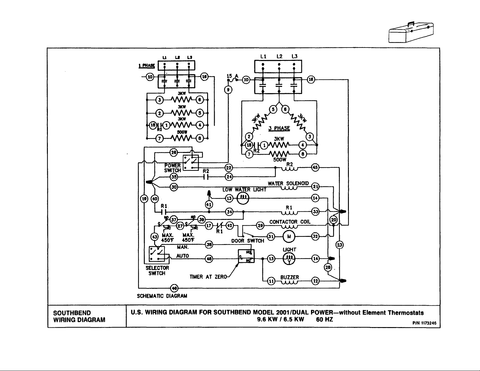
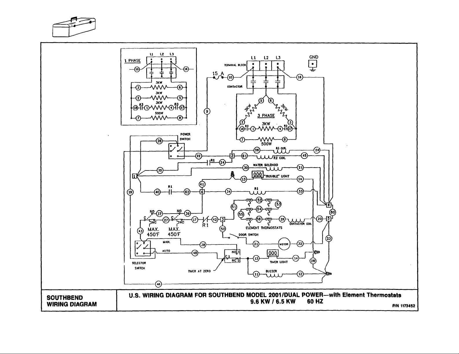
ELECTRICAL CONNECTION:
For proper connection of field wiring to terminal block, see Wiring Diagram, Section 3, Page 7. Be sure that the
input voltage and phase match the requirements shown on the serial plate (located on each piece of equipment).
NOTE: A POSITIVE GROUND CONNECTION IS ESSENTIAL.
NOTE: ALL Steamers are shipped wired for three phase. To convert to single phase see Section One, Page 4.
DO NOT ALLOW ANY TAMPERING OR ADJUSTMENT OF ANY CONTROL OR WIRING. THE UNIT IS
FACTORY SET. ADJUSTMENT OF ANY INTERNAL COMPONENT OTHER THAN THE FIELD TERMINAL
BLOCK CAN VOID THE WARRANTY.
1. Open water valve to full open position.
CHECK:
a. Power to unit.
b. Water to unit.
c. Open drain.
COUNTER TOP CONVECTION STEAMER
SECTION ONE — INSTALLATION
PAGE 3
Page 29

INSTALLATION
Litho in U.S.A.
NOTE: ALL Steamers are shipped three phase. If it becomes necessary to convert from three phase to single phase
follow instructions below.
1. Remove louver panel from rear of steamer
2. Locate contactor in right hand side of rear control compartment and loosen wire terminals on the output side of
contactor.
3. Move wire number 3 from A3 to Al. Refer to diagram below.
4. Move wires number 5 and 6 from A2 to A3. Refer to diagram below.
5. Tighten all wire terminals and replace louver panel. The unit is now converted from three phase to single phase.
COUNTER TOP CONVECTION STEAMER
SECTION ONE - INSTALLATION
PAGE 4
Rev. 12-92
Page 30

INSTALLATION
INSTRUCTIONS FOR STACKING THE 2001:
1. Center one of the 2001s on top of the other, making sure the back bottom comers of the top unit line up with the
back top comers of the bottom unit.
2. Using a felt tip pen, trace around the top unit.
3. Remove the top unit. Spread a bead of high temperature silicone, about the diameter of a pencil, inside the line
drawn in No. 2.
4. Carefully place the top unit on the bottom unit. Seal around edges with silicone to comply with NSF requirements.
5. To install brackets, remove the screws that fasten the bottom plate to the back of the unit. These screws are 3"
from each comer. The hook on the bracket should slide over the lip on the very top of the bottom unit. It may be
necessary to push in slightly on the back louvered panel to allow room for the brackets. Reinstall the screws
through the bracket.
6. Allow 24 hours for silicone to dry before using units.
PERFORMANCE CHECK:
The following items should be checked before or within the first 30 days of operation by a qualified service technician.
1. Check doors for proper alignment and tension.
2. Check door gaskets for wear and sealing ability.
3. Check spray tubes or nozzles for cleanliness and/or leakage.
4. Check all gauges, timers, valves, switches, and motors for proper operation.
5. Visually check control compartment wiring for burned or loose connections.
6. Is user keeping compartment clean?
7. Check electrical load on elements, where applicable, for proper wattage.
COUNTER TOP CONVECTION STEAMER
SECTION ONE — INSTALLATION
PAGE 5
Page 31

COOKING HINTS
Red -
shredded
5lbs. 18-20
27
SPINACH
cut side down
halves
Zucchini, sliced,
5lbs.
SUGGESTED COOKING TIMES:
Timer settings are for general guidance only. Differences in food quality, size, shape, freshness, load size and degree of
cook desired must be considered and adjustments made in time if necessary.
PRODUCT
BATCH
SIZE
APPROX.
COOKING
TIME (MIN)
PRODUCT
BATCH
SIZE
APPROX.
COOKING
TIME (MIN)
FROZEN VEGETABLES* FRESH VEGETABLES*
ASPARAGUS
Cuts and tips 5 IDS. 8-10 Spears 4 Ibs. 12-14
Spears
BEANS
Green or wax - cut 1"
Green - French cut
Lima - Fordhook 5lbs. 16-18 Small 5lbs. 12-14
BROCCOLI
Chopped - tempered 4 IDS. 8-10 CABBAGE
Cut - tempered
Spears 4 IDS. 10-12 Green - wedges, 1/6 cut 5lbs. 20-22
BRUSSEL SPROUTS 4 IDS. 8-10
CARROTS
Sliced
Whole, baby 5lbs. 14-16 CAULIFLOWER
CAULIFLOWER
Flowerettes 4 IDS. 8-10 CELERY
CORN
Cobettes - 3"
Whole Kernel
MIXED VEGETABLES 5lbs. 16-18 On the cob
PEAS
POTATOES
White, whole, small 5 Ibs. 18-20 PEPPERS
Chopped - tempered 6 IDS. 8-10
Leaf - tempered
SUCCOTASH 5lbs. 16-18 peeled, 1 "-3" 7 Ibs. 25-30
ZUCCHINI
Sliced - tempered
*Prepare in 12 x 20 x 2 ½” perforated pan.
5 IDS.
5 IDS.
5lbs.
5lbs.
4 IDS.
5lbs.
5lbs.
6 Ibs.
6 Ibs.
10-12
14-16
20-22
8-10
10-12
14-16
10-12
10-12
- 5"-7" length, 2 pans e ea. pan
18-20
8-10
BROCCOLI
BEANS
Green, 1 "-2" cut 5lbs. 13-15
BRUSSEL SPROUTS
Large 5lbs. 16-18
Green - shredded
CARROTS
Sliced – ½” 7 Ibs. 17-19
Flowerettes
1 "-2" cuts
3"-4" cuts in solid pan 5lbs. 14-16
w/chicken broth added
CORN
5"-7" length 1 14 ears
On the cob 1
Green, large, 14
POTATOES
Red boilers, whole,
Red boilers, whole,
peeled, 1"-3", 3 pans ea. pan
SPINACH
Leaf 2 Ibs. 4-5
SQUASH
Zucchini, sliced, 3/16” 5lbs. 7-8
3/16” - 2 pans ea. pan
COUNTER TOP CONVECTION STEAMER
5lbs.
6 Ibs.
5lbs.
14 ears
7 Ibs.
SECTION TWO — USER'S GUIDE
12-14
14-16
14-16
13-15
18-20
5-7
45-50
12-13
PAGE 3
Page 32

COOKING HINTS
Semolina
2lbs. 18-22
WILD EXTRA FANCY
Litho in
U.SA.
PRODUCT
BATCH
SIZE
FRUIT
CRANBERRIES
Fresh-12 x 20 x 2 ½” solid pan - use
3 cups water and 5 cups sugar
PRUNES
Dried and pitted - 12 x 20 x 2 ½” solid
pan - add 4 cups hot water and sugar
to taste
4 lbs. 8-10
halfway through cooking cycle.
4lbs. 8-10
APPROX.
COOKING
TIME (MIN)
PRODUCT
PASTA
Prepare in 2 ½” deep perforated pan nested inside solid 12" x
20" x 4" pan. Cover with hot tap water. Add salt and oil if
desired and stir. Stir again
SPAGHETTI
Semolina 2lbs. 12-14
MACARONI
BATCH
SIZE
APPROX.
COOKING
TIME (MIN)
RICE AND DRIED BEANS
Prepare in 12" x 20" x 2 ½” solid pan unless otherwise indicated.
Add hot tap water; salt and oil as desired. Stir before placing in
steamer. Do not cover.
WHITE LONG GRAIN CONVEF TTED
2 ½ quarts water, salt, oil 2 lbs. 30-35
6" deep pan, 6 ½ lbs. 40-45
6 ½ quarts water (1 gal)
WHITE MEDIUM GRAIN
1 ¾ quarts water 2 lbs. 22-25
BROWN LONG GRAIN PARBO ILED
1 ½ quarts water 1 ¾ Ibs. 25-30
1 ½ quarts water, 2 pans 1 ¾ Ibs. 30-35
5 cups water 1 Ib. 60-65
KIDNEY BEANS
4 quarts hot water. Steam 4
minutes. Remove; cover; let stand
one hour. Remove cover.
Continue steaming.
NAVY BEANS
3 quarts hot water. Steam 2
minutes. Remove; cover; let stand
1 hour. Remove cover. Continue
steaming.
NOODLES
Egg, Semolina 2lbs. 12-14
Lasagna, Semolina 2lbs. 15-18
EGGS
Prepare in 12" x 20" x 2 ½” perforated pan, unless indicated.
Remove eggs from refrigerator 1 hour prior to cooking.
SOFT COOKED
Large
HARD COOKED
Large, in shell Large, cracked
into oiled solid pan - for salad
SCRAMBLED
Add margarine and spices if
ea. pan
2lbs. 2-50 CHICKEN
4-50
desired. Stir with wire whip after
15 minutes. 4" solid pan. Mixture
in 5-lb. poly film bag, frozen.
Cover with hot water in 4" pan.
Stir after 25 min.
POACHED
In poaching pan or water 8 3-4
POULTRY
Prepare in 12" x 20" x 2 ½” perforated pan. Place solid pan
underneath to catch juice.
4 doz. 8-10
4 doz. 12-14
4 doz. 10-12
6 doz.
2 bags
18-20
45-50
COUNTER TOP CONVECTION STEAMER
SECTION TWO — USER'S GUIDE
PAGE 4
Whole, as purchased 4lbs. 40
Quarters, 8-9 oz. 14 pcs. 18-20
Quarters, 8-9 oz., 2 pans 14 pcs. 24-27
ea. pan
Rev. 12-92
Page 33

APPROX.
APPROX.
BATCH
COOKING
BATCH
COOKING
Frozen,
12" x 20" x 6" Two
1"
water. Cook to
180°
per Ib.
Steam in solid pan with
Stir at
30
minutes.
10
Ibs. 40
DINNER ROLLS
per Ib.
HOT DOGS
TORTILLAS
thawed
5
Ibs. 5 perforated pan or on
8oz. 1-2
COOKING HINTS
PRODUCT SIZE TIME (MIN) PRODUCT SIZE TIME (MIN)
MEAT
MISCELLANEOUS
Prepare in 12" x 20" pan - depth as indicated. CHEESE SOUP
BEEF
Clod - 4" solid pan; add
pan. Water or milk added. 4-lb. tubs 40
Stir at 15 and 30 minutes.
internal temperature 15-17 Ibs. 13-15 BLANCHING NUTS
Ground - 4" solid pan.
CORNED BEEF BRISKET
Raw - cured, 2 ½” solid
1 cup water.
Pre-baked, frozen. Reheat
in perforated pan or on
pan; add ½” water. 9 Ibs. 18-22 pan shelf, uncovered.
2 ½” perforated pan,
2 ½ ‘ perforated pan,
FISH
Prepare in 12" x 20" x 2 ½” perforated pan.
Place solid pan underneath to catch juice.
COD PORTIONS
Thawed - 4 oz. size 3 Ibs. 8-10
OYSTERS
In shell - 18-20 per pan 1 pan 12
In shell - 18-20 per pan 3 pans 15-20
Slightly overlap on
pan shelf. 6-8 1-2
Cooked. To reheat place in
perforated pan or strainer.
4-5
3-4
COUNTER TOP CONVECTION STEAMER
SECTION TWO — USER'S GUIDE
PAGE 5
Page 34

COOKING HINTS
END USER TIPS:
Litho in U.S.A.
Schedule cooking of fresh vegetables so that they will be served soon after they are cooked. If it is necessary to
prepare them in advance, they can be plunged into cold water, drained thoroughly and held under refrigeration until
needed for service.
Five pounds of cold cooked vegetables can be reheated in the steamer in 5 to 10 minutes, depending upon the
variety.
Adding salt to the water for eggs cooked in the shell makes the cooking water more efficient and faster at its job. If
the egg cracks, the white is cooked at the crack and is sealed right away.
To avoid the dreaded green yolk (which is a deposit of iron sulfide) chill the eggs immediately after removing from
the steamer by plunging them into a cold water bath (preferably containing ice).
A quick and easy way to cook eggs for a salad mixture is to crack them directly into a solid steam table pan which
has been lightly coated with salad oil. Do not mix. Steam until they are hard cooked. Remove and chop as you would
for egg salad. The job of peeling has been eliminated.
Transfer steamed hot chicken to deep pan, cover with Cacciatore Sauce and finish in Marathoner oven. Bake 20 to
30 minutes. May be held on steam table.
After cooking, chicken may be browned in Infra-Red or Radiant Broiler. Brush with melted margarine mixed with
salad oil to give a golden brown color.
Use juice saved from steamed chicken to make soups, sauces, or casserole dishes.
Chicken may be steamed in advance and held under refrigeration for next day's use. Be sure to bring product back to
180 °F before serving.
Save the juice from the corned beef. After the cabbage has been steamed, place it in a solid pan and add the juice for
flavoring and holding on a steam table.
Steaming brisket in the 2001 Steamer is a definite time saver. Boiling in water takes 40 to 50 minutes per pound.
Using the 2001 can save 50% in cooking time.
Cabbage when steamed, retains its color and wedge identity. It will not break apart as it does when boiled in an open
pot.
When open, the door can be used as a convenient pan holder while seasoning, loading or unloading.
When removing items prepared in a perforated pan put a solid pan on the door shelf to hold the pan of cooked food.
This will prevent dripping on the floor.
The 2001 is designed to accept standard 12 x 20 pans the way you naturally carry them. Fractional size pans can be
used as well with the optional perforated shelf.
For stirring, the pan does not have to be removed from the steamer. Pull pan 1/3 way out of the cavity and the entire
surface is accessible.
The door may be opened at any time during operation to remove or add food.
Possibility of overcooking is eliminated during the automatic cycle because the elements shut off when the buzzer
sounds.
COUNTER TOP CONVECTION STEAMER
SECTION TWO — USER'S GUIDE
PAGES
Rev. 12-92
Page 35

COUNTER TOP CONVECTION STEAMER
SERVICE
ADJUSTMENTS
WARNING:
ADJUSTMENTS AND SERVICE WORK MAY BE PERFORMED ONLY BY A QUALIFIED
TECHNICIAN WHO IS EXPERIENCED IN, AND KNOWLEDGEABLE WITH, THE OPERATION
OF COMMERCIAL COOKING EQUIPMENT, HOWEVER, TO ASSURE YOUR CONFIDENCE,
CONTACT YOUR AUTHORIZED SERVICE AGENCY FOR RELIABLE SERVICE,
DEPENDABLE ADVICE OR OTHER ASSISTANCES, AND FOR GENUINE FACTORY PARTS.
The following is a brief explanation of the operation of your Southbend Series 2001 Electric Convection Steamer.
The unique design of the Southbend Convection Steamer allows you to cook with steam without the problems of
bulky, troublesome steam boilers. The Southbend 2001 Dual Power Series uses 9.5 KW or 6.5 KW (your choice).
The Southbend Steamer generates its own steam on the bottom of the cooking compartment.
With the selector switch in the "OFF" position, you should have AC across selector switch. If not, check fuse.
When selector switch is placed in the "LO" or "HI" position and second one to "MANUAL" position, voltage is
applied to the coil of contactor from line 4 at terminal block; through fuse; through both selector switches; through
safety thermostats; through relay. Voltage is also applied to water solenoid. Solenoid furnishes 3/8" water
(overflow drain installed) to the floor of the cooking compartment, which turns to steam when heating elements get
hot. Heating elements are fastened directly under the floor of the cooking compartment and heat the water through
direct conduction.
NOTE: From a cold start, the unit should be up to temperature within 4 to 5 minutes.
When contactor energizes, the higher rated voltage is applied to heating elements through the closure of contactor
contacts L1, L2, and L3; from the LINE voltage at terminal block.
NOTE: Interior element also cycles in parallel with heating elements.
Interior element super-heats and dehumidifies the steam in the cooking compartment.
NOTE: The fan will not operate if the door is open, due to safety interlock door switch.
Anytime the unit is turned "ON," a small amount of water will be noticed coming out of the drain-line. This is due
to a "water mist," which is sprayed across the exhaust of the cooking compartment. This eliminates any possibility
of "live" steam ever reaching a drain line. This feature is required by law on ALL pressure less, atmospheric
steamers.
NOTE: The water connection into any Southbend Steamer must be cold water.
FOR REPLACEMENT OF HEATING ELEMENTS (See Drawing on Parts Page 4):
For units without thermostatic element control — Serial Number 91G and before.
A. REMOVAL OF ELEMENTS:
1. Close water valve and remove power to the unit.
2. Disconnect field connection to unit.
3. Remove bolts holding unit to table or stand.
4. Turn the unit on its side and remove bottom cover by sliding it toward the rear.
5. To facilitate work, unscrew control panel and electric box and pull out from their position with
disconnecting any wire. Then disconnect 1/8" copper tubing from condenser.
6. Remove the four nuts, lockwashers, element cover and insulation.
7. Remove all nuts, spring washers and bulbs between elements.
8. Disconnect and remove defective elements. Note carefully where each element is connected.
COUNTER TOP CONVECTION STEAMER
SECTION THREE — SERVICE
PAGE 1
Page 36

ADJUSTMENTS
Litho in U.S
-A-
FOR REPLACEMENT OF HEATING ELEMENTS (See Drawing on Parts Page 5):
For units with thermostatic element control — Serial Number 91H and after.
A. REMOVAL OF ELEMENTS;
1. Close water valve and remove power to the unit.
2. Disconnect field connection to unit.
3. Remove bolts holding unit to table or stand.
4. Turn the unit on its side and remove bottom cover by sliding it toward the rear.
5. To facilitate work, unscrew control panel and electric box and pull out from their position with
disconnecting any wire. Then disconnect 1/8" copper tubing from condenser.
6. Disconnect wires from thermostats and set loose wires aside.
7. Remove the four nuts, lockwashers, element cover and insulation.
8. Remove all nuts, spring washers and bulbs between elements.
B. INSTALLATION OF NEW ELEMENTS (See Drawing on Parts Page 4):
For units without thermostatic element control — Serial Number 91G and before.
9. Make sure the new elements are of correct voltage. Voltage marked on elements must be exactly the
same as marked on the nameplate of the unit.
10. Completely coat the machined side of the element with #PN-126 thermal grease. (Failure to do so will
result in inadequate heat transfer from the element into the steamer bottom plate, causing the low water
light to come on.)
11. Before installing elements make sure to have clean surfaces (on stud plate and elements) except the white
thermo grease.
12. Reinstall elements. Markings should be visible.
13. Install bulbs, flat washers, spring washers and nuts. A maximum of 70 inch/pounds torque should be on
nuts.
14. Connect the new elements in accordance with the wiring diagram.
15. Place the insulation over and around. Use a new insulation if the original one is broken.
16. Place the element cover over the insulation plate with lockwashers and four nuts.
17. Install the bottom cover and turn the unit on its base.
18. Fasten the unit to stand or counter top and seal to the counter top.
19. Connect field wiring and water line and open water valve.
20. Connect drain extension if so equipped, making sure that drain vents freely.
21. Reset power to the unit, turn unit ON and test amperage on each phase and each element. R
INSTALLATION OF NEW ELEMENTS (See Drawing on Parts Page 5):
For units with thermostatic element control — Serial Number 91H and up.
9. Disconnect and remove defective elements. Note locations of wires.
10. Make sure the new elements are of the correct voltage. Voltage marked on elements must be the same as
marked on unit serial plate.
11. Completely coat the machined side of the element with PN-126 thermal grease. Failure to do so will
cause inadequate heat transfer and may severely damage unit.
12. Before installing elements, make sure bottom surface is clean.
13. Reinstall elements. Markings should be visible, (rough side).
14. Install hi-limit bulbs, flat washers, spring washers and nuts. Torque securing nuts to 70 in/lbs.
15. Install (2) new thermostats on new element, tighten snug to casting surface.
16. Reinstall the element insulation board. Use new insulation if broken.
17. Connect the wires back to the elements per the wiring diagram.
18. Reinstall the sheet metal insulation cover and securing nuts.
19. Reinstall thermostat wires to thermostats. Refer to wiring diagram or sticker inside lower side panel.
20. Install the bottom cover and turn unit on its base.
21. Fasten unit to stand or countertop.
22. Connect field wiring and waterline. Open water valve.
23. Connect drain piping.
24. Reset power to unit. Turn unit on and check amperage on each leg of supply wires.
COUNTER TOP CONVECTION STEAMER
SECTION THREE — SERVICE
PAGE 2
Rev. 12-S2
Page 37

ADJUSTMENTS
FOR REPLACEMENT OF MOTOR (Disconnect Electric Field Connections):
A. REMOVAL OF FAN:
1. Remove plastic plug and set screw on the fan hub. An adhesive (LOCTITE or equivalent) may have been
used to prevent loosening of set screw. In such case, the set screw may have to be heated to soften the
adhesive and allow removal. An electric soldering iron or gas soldering torch may be used.
2. Insert a bolt one inch (25 mm) or longer into the threaded hole at the end of the fan hub. Tighten the bolt
against the end of the motor shaft until fan slips off.
Caution: If fan does not move on shaft while tightening the bolt against the end of the motor shaft, spray
penetrating oil (WD-40 or equal) into plug and set screw holes every few minutes until fan can be removed
without damage.
R REMOVAL OF MOTOR:
3. Remove seal and clean shaft.
4. Remove electric wires from motor. Note which terminals the wires were attached to. Incorrect wiring could
damage the motor.
5. Remove motor assembly.
6. Undo the four lockouts holding the motor to the motor support.
C. INSTALLATION OF NEW MOTOR (See Drawing on Parts Page 2):
7. Fasten the new motor to the support with four locknuts,
8. Install nylon washer between cavity and motor support.
9. Place the new motor assembly in position until the motor shaft is exactly centered in the hole where it
penetrates the cooking compartment; check from the front side.
10. Reconnect wiring to the motor.
11. Place the seal on motor shaft (without grease); thin lip of seal in direction of cavity. Seal should make a good
contact on cavity.
D. INSTALLATION OF FAN (See Drawing on Parts Page 2):
12. Before installing the fan check the following points:
a. The motor assembly must be secure.
b. The motor shaft must be centered in the hole.
c. The motor must turn freely.
d. The seal must be in place on the shaft inside the cooking compartment.
13. Coat the inside of the fan hub and the motor shaft with a high-temperature, waterproof anti-seize compound
(LOCTITE 771 or equivalent).
14. Position fan in place. Apply suitable grade adhesive on set screw threads (LOCTITE or equivalent),
position set screw in place and tighten to secure fan on shaft. Place plastic plug in front hole.
15. Rotate the fan by hand to see if everything is smooth. The fan should rotate freely, not rubbing against
anything.
16. Reassemble interior components and place switch in "MANUAL" position. Within five (5) minutes steamer
should be up to temperature and fan should be running. Check for proper rotation (CCW).
COUNTER TOP CONVECTION STEAMER
SECTION THREE - SERVICE
PAGE 3
Page 38

ADJUSTMENTS
REPLACEMENT OF DOOR GASKET (See Drawing on Parts Page 2):
REMOVAL OF INNER PANEL ASSEMBLY (DETAIL)
Litho in U.S.A.
1. Open door and remove inner panel assembly by sliding panel toward you and lifting out of door.
2. Place panel assembly facing down on a flat surface.
3. Remove the two (2) nuts holding two (2) retaining panels and gasket.
4. Install new gasket around inside panel.
5. Two spacers must be installed on studs inside of panel. Front panel inside of gasket.
6. Install flange deflector down, opposite to the turn-down edge panel and then install two nuts.
7. Place panel assembly in door with turn-down edge of panel nearest you. Slide panel toward you, push
downward and secure turn-down edge by sliding panel toward unit.
8. Close door, turn on unit and test for leaks around the door.
9. If required, door can be adjusted by means of the four screws holding the door to the hinges.
To adjust door, loosen the four screws, position door to obtain light pressure on gasket and tighten the four
screws. Make sure the two comers of the door are in
line with the comers of the unit.
10. Further adjustment is possible by adding or removing
shims under the door catch plate. Removing shims
will increase pressure on top edge of gasket.
If these instructions are followed carefully, door
should be easy to operate and without steam or water
leaks.
NOTE: This unit must be free-venting through the drain.
Any restriction at drain outlet or failure to install drain ac-
cording to installation instructions will cause the steam to
escape around door due to excessive backpressure in the
unit
DOOR HINGE TUBING ASSEMBLY (See Drawing on Parts Page 2):
TO REMOVE:
1. Open door and unscrew (4) #10-32 screws.
2. Remove door hinge each side, freeing the door hinge tubing assembly.
3. Remove torsion springs, inspect for damage; replace if defective.
TO REASSEMBLE:
1. Insert door hinge tubing assembly in between tabs on front frame.
2. Install #10-32 screws, being sure to apply thread sealer.
3. Reinstall door; check for smooth operation.
COUNTER TOP CONVECTION STEAMER
SECTION THREE — SERVICE
PAGE 4
Rev. 12-92
Page 39

building.
KPA)
SERVICE
TROUBLE SHOOTING:
FIRST — CHECK THE BASICS. The unit needs power, water, and an open drain to operate properly.
BASIC #1 — POWER: Is there power to the unit of the proper voltage and phase?
BASIC #2 — LOW WATER: Is there water flowing into the compartment? Be sure all water valves are open.
BASIC #3 — DRAIN: Is the drain line open (no solid connection), short (about three feet), and without
obstructions?
Check the BASICS. Then, and only then, can malfunction of controls be considered.
Refer to "INSTALLATION INSTRUCTIONS" section of this service manual to make sure the unit was installed
properly. After all previous steps have been complied with, proceed with this trouble shooting guide. Carefully check
all symptoms listed to find the one closest to the actual malfunction of your steamer.
NOTE: Improper installation may void warranty.
TROUBLE SHOOTING GUIDE: (Always Press Power Off)
Problem:
Steam leaks around the door. —
No water in the cooking
compartment (or very little
water). Non thermostat element
type: Yellow-Low water light
on or thermostat element type:
Bed—Trouble light on
Look For: Correction:
BASIC #3 - DRAIN The drain either
wasn't installed properly or has developed
an obstruction of some sort, causing a back
pressure in the cooking compartment.
— Worn door gasket. Replace gasket.
—
BASIC #2 - WATER Drain overflow not in
place.
— Water valve shut off. Check any water valves to the unit.
— Water may be shut off elsewhere in
— Waterstrainer may be plugged. Clean as necessary.
— Flow control valve may be plugged. Clean as necessary.
— Tank solenoid may be plugged or not
operating.
— Inlet to cooking compartment may be
plugged.
— Low water pressure. Water pressure must be 30 P.S.I. (207
Check drain line installation. The drain line
must be short, at a slope, not physically
connected to any drain system and without
restrictions. (No drain traps.)
Drain overflow should be inserted in drain
of cooking compartment.
Make sure cold water line to unit is on.
Check tank solenoid.
Clean as necessary.
minimum.
COUNTER TOP CONVECTION STEAMER
SECTION THREE — SERVICE
PAGE 5
Page 40

NOTE: Before fan motor will turn on, door switch must be energized. (Check fuse and Master
SERVICE
Litho in U.S.A.
TROUBLE SHOOTING GUIDE: (Continued)
Problem:
No steam. — BASIC #1 - POWER Is there power to the unit? Does the
Look For: Correction:
supply match the rating on the nameplate?
BASIC #2 - WATER There must be at least 1/4" (6 mm) of
water covering floor of cooking
compartment. (If no water on floor of
cooking compartment, SEE SYMPTOM
#2).
— No power to the contactor coil or defective
contactor.
See Wiring Diagram and trace voltages
through proper circuits.
Check element thermostats.
If Contactor is operating properly, check
both sides of contactor to make certain all
phases are going to the elements.
— Defective heating elements. Check all elements. Replace if necessary.
Defective element thermostats. Check thermostat — contacts should be
NOTE: If elements are replaced, check
Section 3-Page 1 for service procedure.
closed at room temperature.
Fan Motor doesn't run. NOTE: Generally, if you can spin the fan by hand, the motor will not be defective unless it is.
overheating. See cause "E" below.
Switch also.)
— Fuse. Check — replace if necessary. Turn
master switch to manual position.
— Loose door latch. Adjust so door will close and activate
door switch.
Temperature in motor compartment is too
high. (Motor will stop automatically if
overheating — it will reset automatically
when temperature returns to normal.)
There must be at least three inches
clearance at back of unit. Unit must not be
located near high heat-producing pieces
of equipment — see installation
instructions.
Slow cooking or unit won't get
— BASIC #2 - WATER Check Symptom #2.
hot enough to make much
steam.
COUNTER TOP CONVECTION STEAMER
SECTION THREE — SERVICE
PAGE 6
Rev. 12-92
Page 41

COUNTER TOP CONVECTION STEAMER
Serial
91G
and before
PE-196
KNOB FOR TIMER
PARTS
PARTS
WARNING:
INSTALLATION OF OTHER THAN GENUINE SOUTHBEND PARTS WILL VOID THE
WARRANTY ON THIS EQUIPMENT,
The serial plate is located on exterior right side at rear.
Replacement parts may be ordered either through a Southbend Authorized Parts Distributor or a Southbend
Authorized Service Agency.
When ordering parts please supply the Model Number, Serial Number, Part Number, Description, plus Finish, and
Electrical Characteristics, as applicable.
For parts not listed consult a Southbend Authorized Parts Distributor or Southbend Authorized Service Agency. If
necessary, please consult Southbend Parts Department for assistance.
NOTE: NO THERMOSTAT ELEMENT CONTROLS ON UNITS Serial Number 91G and before. Units Serial
Number 91H and up have thermostat element controls and a red trouble light replaces the amber low water
light.
CONTROL PANEL VIEW
KEY NO. PART NO. DESCRIPTION
1 1167592 POLYPANEL, Serial 91G and before
2 A93-00023 POWER SWITCH (PE-172)
3 6600030 LOW WATER LIGHT, 240V, AMBER,
4 PE.195
5 A9340025 AUTO/MANUAL SWITCH (A93-00029)
6 1109900 BUZZER,240V
1173537 POLYPANEL, Serial 91H and after
6600028 TROUBLE LIGHT, 240V, Red, Serial
Not Shown
132282
1174320 CONTROL PANEL, Serial 91H and after
91H and after
TIMER
CONTROL PANEL. Serial 91G and
before
2001 SINGLE POWER CONNECTION
COUNTER TOP CONVECTION STEAMER
SECTION FOUR — PARTS
PAGE 1
Page 42

PARTS
Litho in U.S.A
-
2001 SINGLE POWER CONNECTION
DOOR ASSEMBLY MOUNTING VIEW
KEY NO. PART NO. DESCRIPTION
1 1167325 SCREW. HINGE MOUNT (PH-158)
2 1168259 DOOR PIVOT SHAFT TUBE (132-223)
3 A11.00019 BASKET FRAME (132-305)
4 All-00018 INSIDE PANEL (132-306)
5 A16-00004 DOOR GASKET (132-255)
6 6600367 SPACER (PH-404)
7 6600430 LOCK NUT (PH-406)
8 1167344 DOOR PANEL (Exterior) (132-188)
9 132321 DOOR HINGE BLOCK (Left or Right)
10 6600416 HINGE SPRING (Left) (132-046-1)
11 6600414 HINGE SPRING (Right) (132-046-2)
12 6600412 LOCKWASHER. SS. ¼ (PH-256)
13 6600410 SCREW, HINGE BLOCK (PH-007)
14 1173531 DOOR HANDLE (132-121) (6600376)
1173530 DOOR LATCH
15 6600396 SPRING, HANDLE (Left Hand) (132-018-1)
16 6600398 SPRING. HANDLE (Right Hand) (132-018-2)
17 6600402 SPRING CLIP (PH-307)
18 6600400 PIVOT PIN, HANDLE (132-027-1)
19 11-00029 HOLDING PLATE (132-307)
MOTOR AND FAN
MOUNTING
KEY NO. PART NO. DESCRIPTION
1 132-320 MOTOR. 208-240V
2 1167330 BRACKET. MOTOR (132-013)
3 6600430 LOCK NUT (132-200)
4 1168255 BLOWER WHEEL (132-233, 1167331)
5 A16-00005 SHAFT SEAL - CAVITY (PM-122)
6 A60-00003 WASHER, NYLON (130-135)
7 1167332 SET SCREW (PH-172)
8 A59-00020 HOLE PLUG BUTTON (PM-005)
Kit A03-00030 includes items 3. 4. 5,6 & 7 (132-304)
Kit A03-00054 includes items 8 thru 19 (132-303)
Kit 4440334 Door Latch/catch Improvement Kit includes 1 each:
1173531.1173530.1173529
Kit 6600370 includes items 3 thru 19
2001 SINGLE POWER CONNECTION
COUNTER TOP CONVECTION STEAMER
SECTION FOUR — PARTS
PAGE 2
Rev. 12-92
Page 43

10 1173293
SOLENOID 208
-
240V
PARTS
2001
SINGLE POWER CONNECTION
BACK VIEW OF STEAMER
KEY
NO.
*2 #1173428 Replaces #PP-629 starting Jan 91. Ser91A and up. For older units:
Ser90L and before use #4440329 Kit for first time replacement only and then
#1173428 or #1173429.
ITEM PART NO. DESCRIPTION
1 1173428 STRAINER
1a 1173429 REPLACEMENT SCREEN ONLY FOR 1173428
2 1173432 FOUR INCH NIPPLE
3 PP-634 FITTING FEMALE SWIVEL ¼“ HOSE
4 PP-224 90°ELBOW
5 PP-232 ELBOW ¼ MALE FEMALE
6 PP-204 REDUCER 3/8 MALE 'A FEMALE
15 PP-636 FLOW REGULATOR
8 PP-223 REDUCER 3/8 NPT MALE, ¼ NPT MALE
9 PP-710 BRASS TEE
PART
DESCRIPTION
NO.
1 1173448 CONTACTOR (6600052 - 2001 only)
2 PE-194 RELAY, ELEMENT, 240V (REPLACES PE-181)
3 1167340 COVER. TERMINAL BLOCK (132-195)
4 6600462 BOTTOM COVER PANEL, 2001 (132-024)
5 PE-023 TERMINAL BLOCK SECTION, (4) Req'd.
6 1160031 GROUND LUG
7 1012596 FUSE HOLDER
8 1012510 FUSE, 15 AMP (PE-018.1167336)
9 1173428 IN-LINE STRAINER (REPLACES #PP-629)'
9 4440329 REPLACEMENT STRAINER KIT
9a 1173429 REPLACEMENT SCREEN ONLY FOR 1173428
10 1173293 SEE BELOW
11 A93-00022 HI-LIMIT (PE-171)
12 1167328 FOOT, ADJUSTABLE (OPTIONAL) (PM-018)
13 A19-00014 INSULATION, REAR (132-100-3)
14 A14-00027 INSULATION COVER (132-293)
15 PP.636 SEE BELOW
16 6600466 REAR COVER PANEL
17 A39-00021 BRACKET, DOOR INT. SWITCH (132-245)
18 1172988 DOOR PUSH ROD, 2001
19 1142000 INTERLOCK SWITCH (PE-129)
20 A24-00002 HOSE, CAVITY RLL (132-278)
21 PM-019 CLAMP.HOSE
22 PE-179 RELAY. SMALL
23 1170008 BRACKET. RELAYS (132-314) Serial 91G and before
23 1174309 RELAY MOUNTING BRACKET. Serial 91H and after
24 1170335 TERMINAL STRIP. Serial 91H and after
2
WATER INLET ASSEMBLY
11 PP-206 THREE INCH MALE NIPPLE
12 PP-213 90°ELBOW
COUNTER TOP CONVECTION STEAMER
SECTION FOUR — PARTS
PAGE 3
Page 44

PARTS
Litho in
U.S.A.
INSIDE VIEW OF STEAMER 2001 SINGLE POWER CONNECTION
KEY NO. PART NO. DESCRIPTION
1 A95-00002 ELEMENT, CAVITY, 2001
2 1167320 FAN GUARD, 2001 (132-206)
3 1167323 SIDE RACKS, 2001 (132-180)
4 1173529 DOOR CATCH (132-042) (6600434)
6600509 DOOR CATCH SHIM (132-105-1)
5 1172964
1167321
6 6600044 PUSH BUTTON (132-079-2)
7 1168255 BLOWER WHEEL. 2001 (132-205)
8 1167332 SET SCREW. BLOWER WHEEL (PH-172)
9 A1640004 GASKET, DOOR. 2001 (132-255)
10 All-00018 INSIDE PANEL. DOOR. 2001 (132-304)
11 13206-3 DRAIN TUBE/PLUG W/CHAIN /
12 6600244 WATER FILL JET (132-028-1)
13 6600248 GASKET. WATER JET (132-138)
14 1146403 NUT, WATER FILL JET
15 A81-00004 SLIDE KIT
16 1167263 ARM DOOR SLIDE (132-195)
17 A81-00049 PIVOT KIT (132-309,132-312)
18 6600454 DRAIN PAN (132-033)
DOOR CATCH SCREW*
DOOR CATCH SCREW (PH-004)'*
(1173168,1167322)
1
*1 #1172964 for units produced Jan. 91 and after. Ser91A and up.
#1167321 for units produced Dec. 90 and before. Ser90L and before.
MOUNTING VIEW - ELEMENTS
FOR UNITS WITHOUT THERMOSTATS ON
ELEMENTS SERIAL NUMBER 91 G & BEFORE
KEY NO. PART NO. DESCRIPTION
1 1146413 NUT, ¼ -20 (PH-202)
2 1146500 LOCKWASHER, 1/4 (PH-251)
3 A14-00026 COVER, ELEMENT INSULATION (132-295)
4 A19-00011 ELEMENT INSULATION, MAIN (132-294-1)
5 PH-422 SPRING WASHER
6 A60-00005 WASHER, LIMIT THERMOSTAT (132-296)
7 1174304 ELEMENT 208V (132-264-1/1168029)
1174305 ELEMENT 240V (132-264-2/1168028)
8 A19-00012 ELEMENT INSULATING BLOCK -
9 A19-00013 ELEMENT INSULATING - SIDES
PN-126 THERMAL GREASE
FRONT/REAR (132-294-3)
THERMO JOINT COMPOUND (132-294-2)
COUNTER TOP CONVECTION STEAMER
SECTION FOUR — PARTS
PAGE 4
Rev. 12-92
Page 45

2001 THERMOSTATIC
UNDERSIDE COMPONENTS/WIRING ROUTING
MOUNTING VIEW - ELEMENTS
FOR UNITS WITH THERMOSTATS ON ELEMENTS
KEY NO. PART NO. DESCRIPTION
SERIAL NUMBER 91 H & AFTER
1 1146413 NUT, ¼ -20 (PH-202)
2 1146500 LOCKWASHER. ¼ (PH-251)
3 1174307 COVER. ELEMENT INSULATION
4 1174306 ELEMENT INSULATION, MAIN
5 PH-422 SPRING WASHER
6 1174308 RETAINER. Hl-LIMIT BULB
7 1174304 ELEMENT 208V
1174305 ELEMENT 240V
8 A19-00012
9 A19.00013
10 1174302 THERMOSTAT. ELEMENT. (6)
11 1174300 WIRE ROUTING CHANNEL
12 1161675 BUSHING (9)
13 1174299 WIRE ROUTING SUPPORT
14 1174301 WIRING SHIELD
PN-126 THERMAL GREASE
PARTS
ELEMENT INSULATING BLOCK FRONT/REAR (132-294-3)
ELEMENT INSULATING - SIDES THERMO
JOINT COMPOUND (132-294-2)
COUNTER TOP CONVECTION STEAMER
SECTION FOUR — PARTS
PAGE 5
Page 46

INSTRUCTIONS
PARTS
Litho in U.S.A.
CONDENSOR
KEY NO. PART NO. DESCRIPTION
1 A12-00027
2 6600329 INLET FLANGE. CONDENSOR
3 6600241
4 P4119 FITTING
5 6600334 SCREW
6 6600316 TEFLON WASHER (130-169)
CONDENSOR. CONDENSOR BOX
ONLY
SPRAY NOZZLE. CONDENSOR (PP-
632)
MISCELLANEOUS PARTS NOT SHOWN IN
PHOTOS OR DRAWINGS
KEY NO. PART NO. DESCRIPTION
1167328 ADJ. FOOT ONLY (PM-018)
1172857 STEEL LEG ASS'Y. SET OF 4. (optional)
(6600362)
1163561 STEEL LEG ASS'Y. (1 only) (PM-015)
(6600361)
1173012 OWNERS MANUAL
1173354 LAMINATED CLEANING
COUNTER TOP CONVECTION STEAMER
SECTION FOUR — PARTS
PACE 6
Rev. 12-92
 Loading...