

South S82V User Manual

Contents
Contents...........................................................................................................................................................................1
C
hapter I : A brief introduct
C
hapter II : S82V receiver main unit .....................................................................................................................3
C
hapter
App
Ⅲ : S82V acc
end
ix 1: Frequently Asked
Contents
essor
ion of S82V
ies
............................................................................................................................... 10
Quest
...............................................................................................................2
ion
s..........................................................................................................
17
GPS Page 1 of 17 S82V

Ch
apter I : A brief introduction of
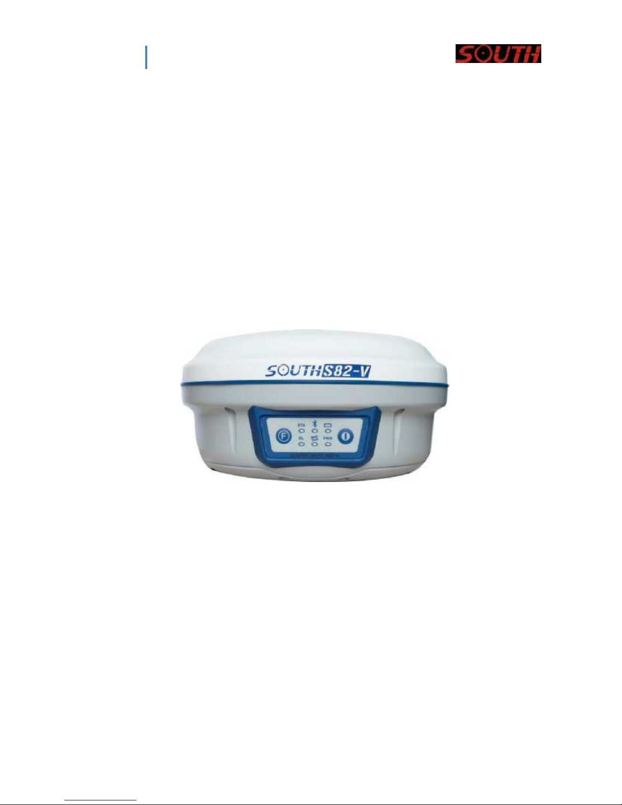
Chapter I: A brief introduction of S82V
S82V
The SOUTH S82V is a RTK GNSS receiver, built for pr
S82V is able to r
The S82V
Bluetooth device to facilitate working
eceive GPS signals, and also
main r
eceiver
unit is integrated with
sat
convenience for
ecision, r
eliab
ility and
user friendliness.
ellite signals from GLONASS and GALILEO.
GNSS antenna interf
the user.
ace,
GNSS
module,
The S82V receiver is lightweight and sturdy, and designed for rugged usage. The receiver
housing is waterproof and dustproof, and built with superior material to withstand long lasting
operat
The
appl
This dev
two
accept any int
CA
ion in the field.
embedded r
ications. The data tr
ice complies with P
eceiver
firmware can cu
ansf
er pro
art 15
conditions: (1) this device ma
erference received, including interference that may cause und
UTION:
stomize d
cess is a
y not
very
of
the FCC Rules. O
cause
ifferent RTK
convenient one.
peration is
harmful int
erferen
software for differen
subject to
ce, and (2)
the following
this device must
esired operation.
t
a) The disposal of electric and electronic device as solid urban waste is strictly prohibited:
they must be collected separately.
b) Contact Local Authorities to obtain practical information about correct handling of the waste,
location and times of waste collection centres. When you buy a new device of ours, you can
give back to our dealer a used similar device.
c) The dumping of these devices at unequipped or unauthorized places may have hazardous
effects on health and environment.
d) The crossed dustbin symbol means that the device must be taken to authorized collection
centres and must be handled separately from solid urban waste.
NOTES:
The treatment, recycling, collection and disposal of electric and electronic devices may vary in
accordance with the laws in force in the Country in question.
You could contact e
GPS Page 2 of 17 S82V
xport@sou
thsurvey.com for any enquiries
pertaining to the S82V.
2
Ch
apter II :
II.1
T
the main
structure. The co
The receiver main body
here are
three parts to
Chapter II: S82V receiver main unit
S82V receiver
main unit
the main unit:
ver protects
the GNSS antenna in
the cover, a
side. The
prot
prot
ective rubb
ective rubb
er ring and
er ring
has the function of additional prot
and
control keys are int
for
the b
uilt-
r
eceiver (Bl
the r
eceiver.
in a
uetooth dev
egrated into front of
compart
ment for
ice,
main board, etc.) are contained in
F
ig. 2.1
ect
ion against water and dust. The display LED panel
the main structure. On the bottom
the batteries. All the others
components of
there is a slot
side the main structure
– S82V ma
in unit
the
of
GPS Page 3 of 17 S82V
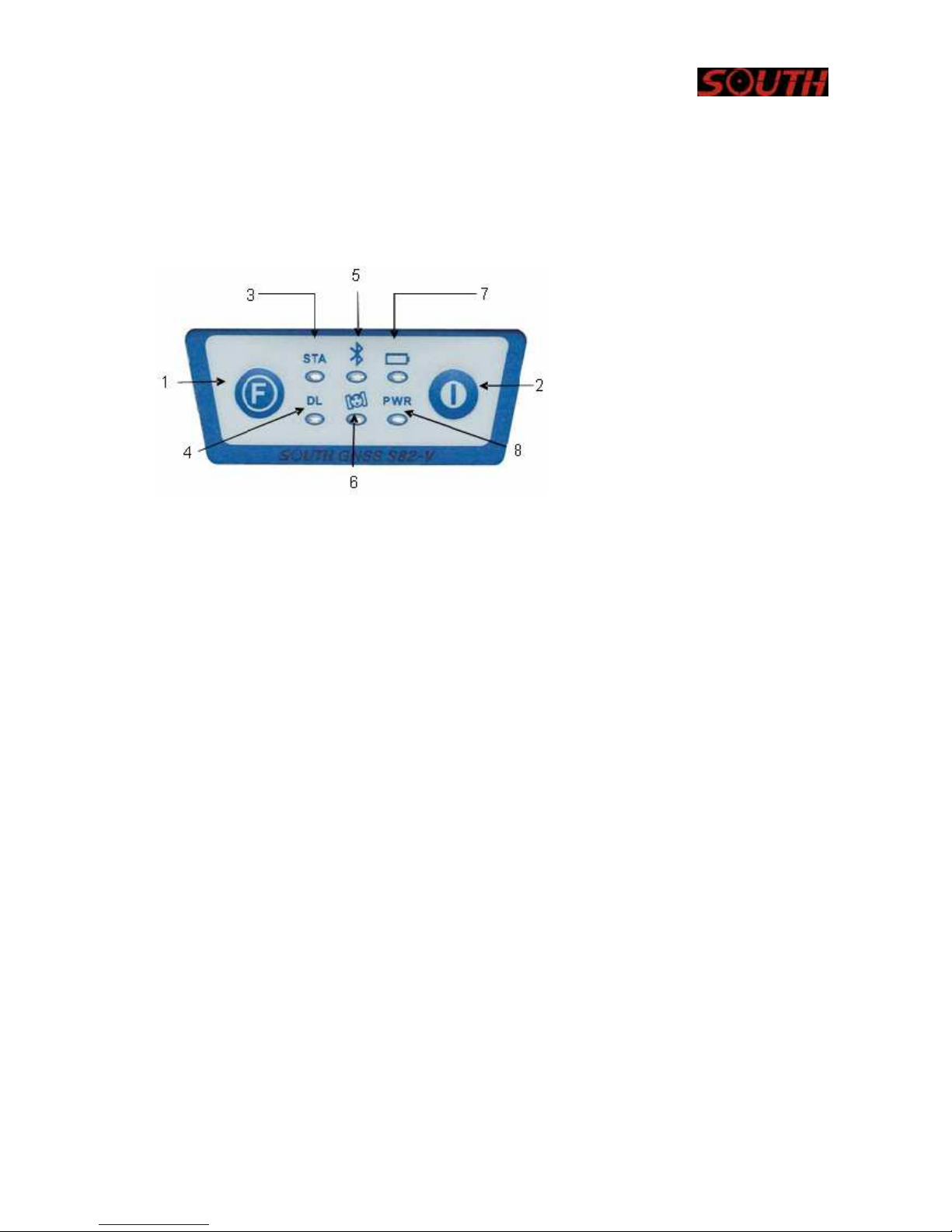
II.2 Indicator lights and instrument setup
Fig.
2.2
– S82V k
eys and indicator lights
As you see by the f
colors and two d
igure 2.2
ifferent funct
there are
ions.
three sets of ind
1.
Function Key
2.
Pow
er Ke
3.
Status light
4.
Data li
5.
6.
7.
8.
icator L
Bluetooth light
Satellite light
Built-i
External power supply light
EDs, each with two different
y
nk light
n pow
er su
pply light
From the l
st
1
indicator: status indicator light (red), data link ind
eft to the right are:
nd
2
indicator:
Bluet
ooth ind
icator l
ight (red), sat
rd
3
indicator: Battery power light (red), ext
The descript
ions
of
the LEDs
are as follows
BAT (red): Built-in power supply light (Fig.2.3).
The status of
the battery power supply are ind
1. Fixed:
Battery power supply in good
2. Flashing: Battery power supply low.
U
sually w
hen the light begins to fl
ash you have
icator light (green)
ellite indicator light (green)
ernal
power supply ind
icated as follows
condition.
one hour of power left.
icator light (gree
n).
GPS Page 4 of 17 S82V
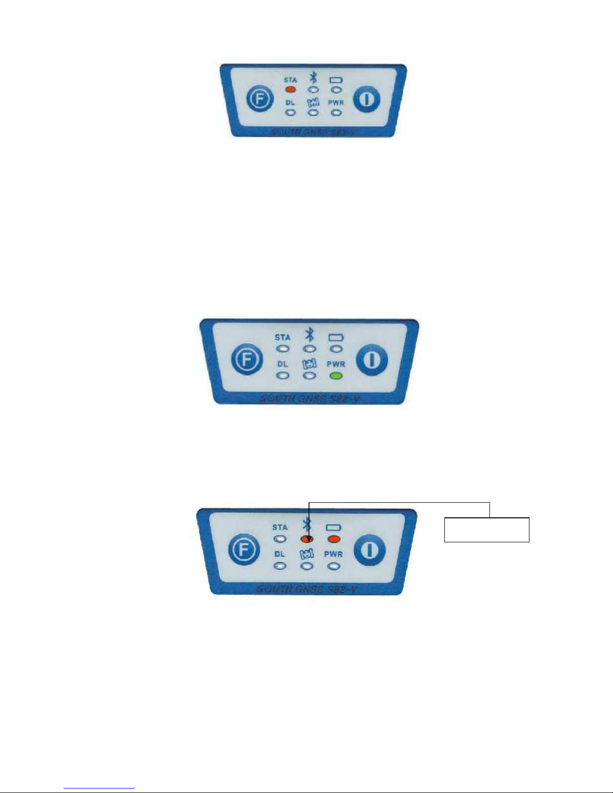
PWR (green): external
The status of
1. Fixed: Ext
2. Flashing: External
the external
ernal
F
ig. 2.3
– S82V batter
y power LED
power supply light (Fig. 2.4).
power supply are ind
icated as follows
power supply in good condition.
power supply l
ow
F
ig. 2.4
– S82V external
BT (red): Bluetooth ind
icator l
ight (Fig. 2.5).
When
the controller is
SAT (gr
een): Sat
connected with the r
F
ig. 2.5
– S82V Bluetooth LED
ellite light (F
ig. 2.6).
It
shows the amount of located satellites, when
power LE
D
eceiver, this light will light up.
the r
eceiver obtains satellites signals, it w
Bluetooth light
ill
start to blink, the numb
GPS Page 5 of 17 S82V
er of blinks corresp
onds with
the number of located
sat
ellites.
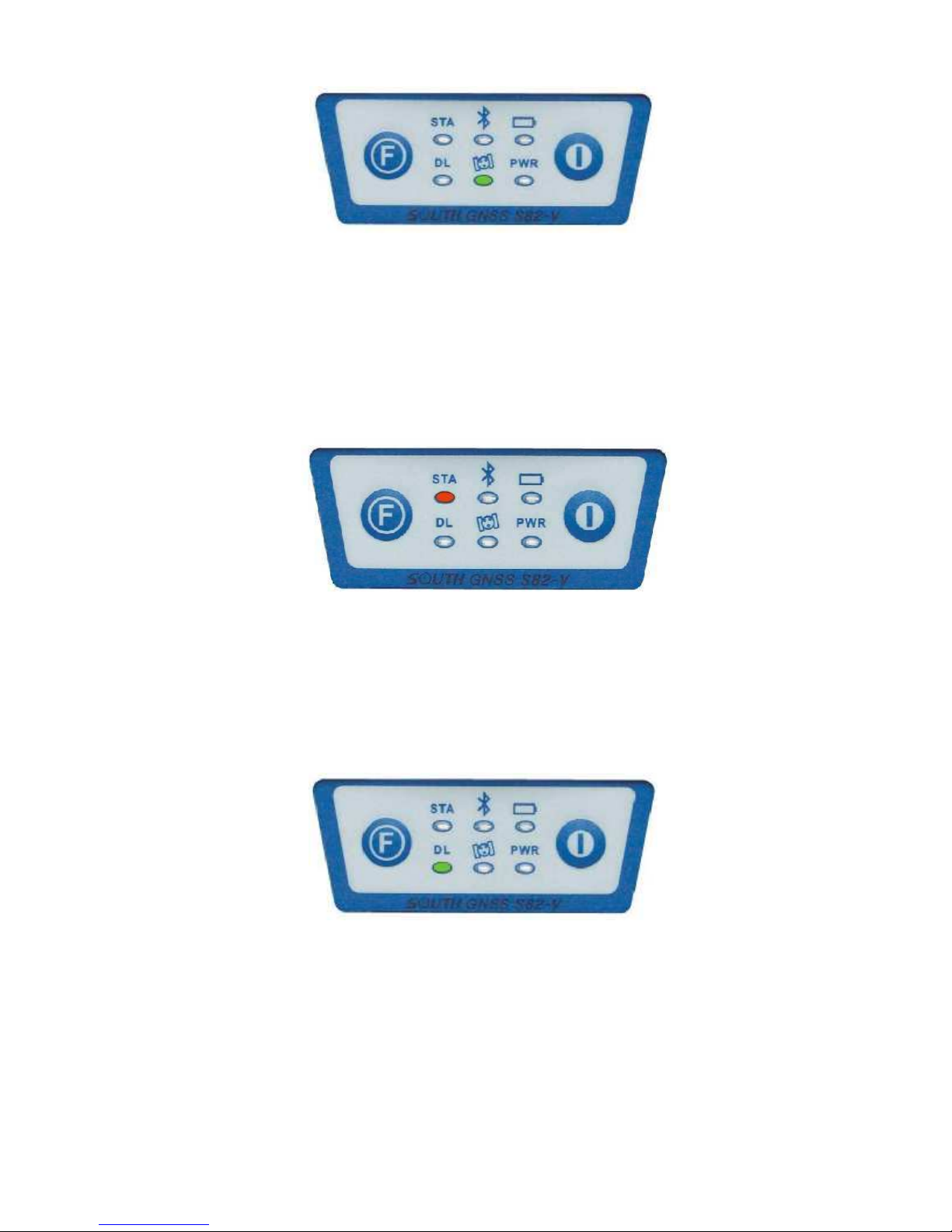
In static mode,
data link
STA (red): Status light (Fig. 2.7).
module working in good condit
this LED lights w
F
ig. 2.6
hen the r
–
S82V satell
ite LED
eceiver is recording data. In RTK
ion.
mode, it
shows if the
F
ig. 2.7
–
S82V status LED
DL (green): Data Link light (F
ig. 2.8).
In static mode, it will remain lit in
data link
F Key : F
module working in good condit
unction ke
y
nor
mal operat
ion.
F
ig. 2.8
ion
–
S82V Data Link LED
conditions. In RTK mode, it
Switches between
the working modes (static, b
ase or rov
er) and RTK
P Key: Power ke
y
Powers unit on/off and
GPS Page 6 of 17 S82V
conf
irms sel
ected funct
ions.
communi
shows if the
cat
ion
mod
es.
 Loading...