

Page 1
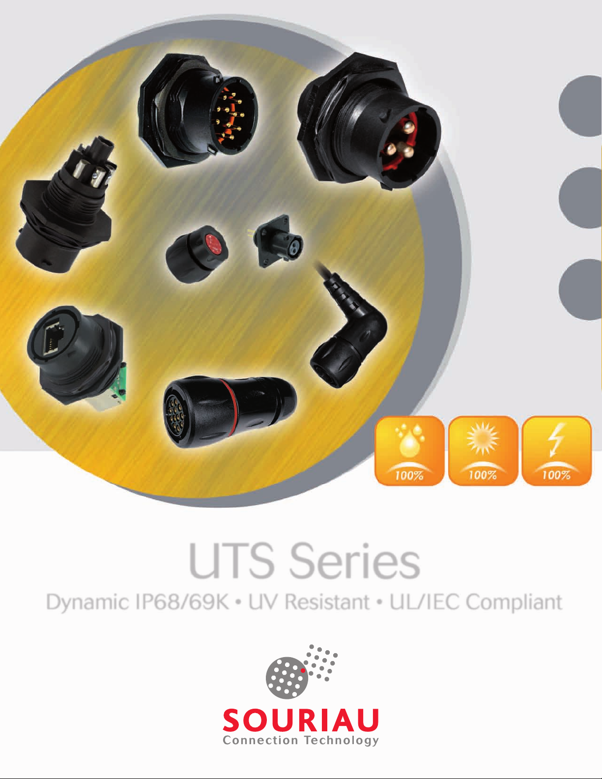
UTS Series
Dynamic IP68/69K • UV Resistant • UL/IEC Compliant
Page 2

Page 3
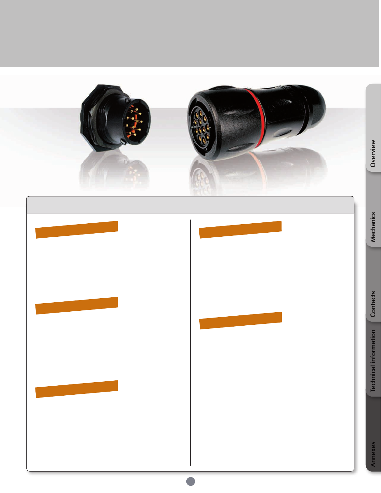
UTS Series
Overview
Contents
Overview
How to read our catalogue ......................................
UTS range overview ....................................................
General technical characteristics ...........................
UTS layout guide .........................................................
Contacts layout ............................................................
De-rating curves ..........................................................
Mechanics
UTS plug cable gland backshell .............................
UTS square ange receptacle .................................
UTS jam nut receptacle with accessories ............
Solder tail protrusion ..................................................
UTS in-line receptacle with accessories ..............
Accessories ....................................................................
Cable assembly .............................................................
Contacts
Description ....................................................................
Contact plating selector guide ................................
Contact selector guide ..............................................
Packaging ......................................................................
Crimp contacts .............................................................
Coaxial contacts ..........................................................
PCB contacts ................................................................
Fibre optic contacts ....................................................
06
07
10
12
13
14
24
26
28
30
32
34
36
40
41
42
42
43
45
46
47
Technical information
Tooling ............................................................................
Assembly instruction ..................................................
Rated current & working voltage ............................
UV resistance ...............................................................
Crimping .........................................................................
UL94 + UL1977 ..........................................................
IEC 61984 with IP code explanation ....................
What is NEMA rating ? ..............................................
Annexes
Coaxial contacts - cabling notices .........................
Glossary of terms ........................................................
Coordinates for PC tail terminations .....................
Stand off dimensions - Drilling pattern .................
Discrimination/Keying methods .............................
Mechanics
52
54
58
59
59
60
63
65
ContactsTechnical informationAnnexes
68
75
76
78
79
3
Page 4

Page 5
UTS Series
Overview
How to read our catalogue ..........................................................................................................
UTS range overview ........................................................................................................................
General technical characteristics ...............................................................................................
UTS layout guide .............................................................................................................................
Contacts layout ................................................................................................................................
De-rating curves ..............................................................................................................................
06
07
10
12
13
14
Page 6
UTS Series
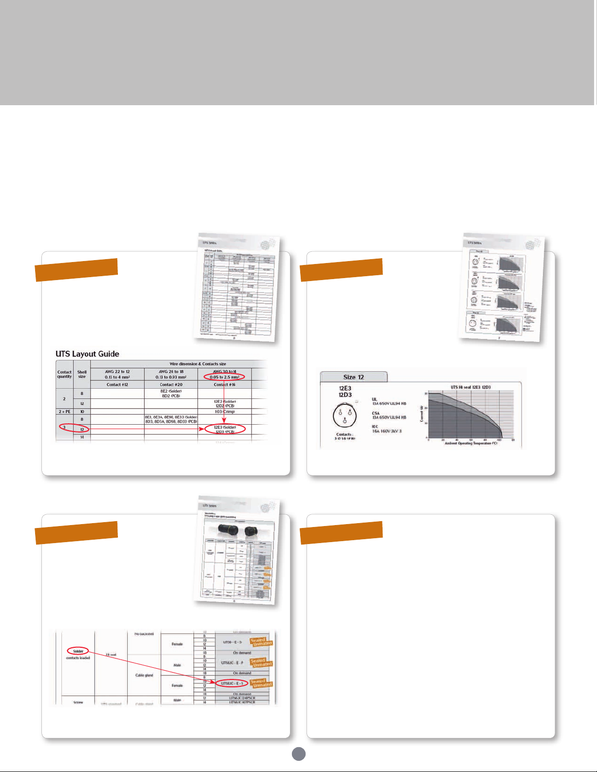
How to read our catalog
Example:
A 3 x 1.5mm² multicore cable carrying 10A of continuous current needs to be connected to a weatherproof enclosure.
The enclosure contains some expensive electronics, so it is important to ensure that it remains sealed even when the cable is not connected.
Step 1
Use the layout guide page 12. Check if your layout can run at 10A
12E3 (for solder contacts)
or 12D3 (for PCB)
Step 3
Step 2
continuous using the dedicated
de-rating curve (see pages 14 to
20).
Step 4
Choose your plug and receptacle.
In our example we chose a plug
with solder contacts.
Your selection should be:
UTS6JC - E - S
Using the UTS layout guide you can select the insert
arrangement code according to your needs. Replace - - by your
choice 12E3 for solder contacts.
Result:
Here your plug with solder contacts is UTS6JC12E3S
For any assembly questions please refer to the “assembly
instruction” section (pages 54 to 57).
For discrimination see p.79.
Plug with solder contacts:
UTS6JC - E - S
6
Page 7
UTS Series
UTS range overview
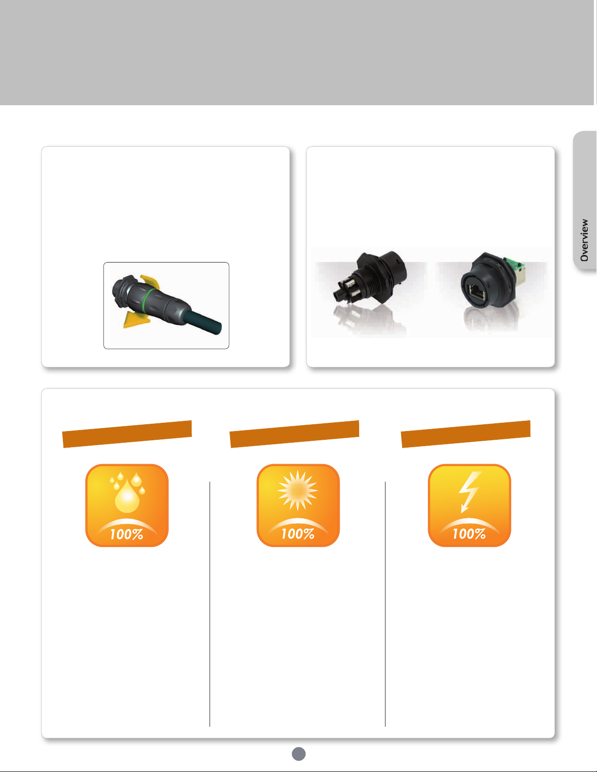
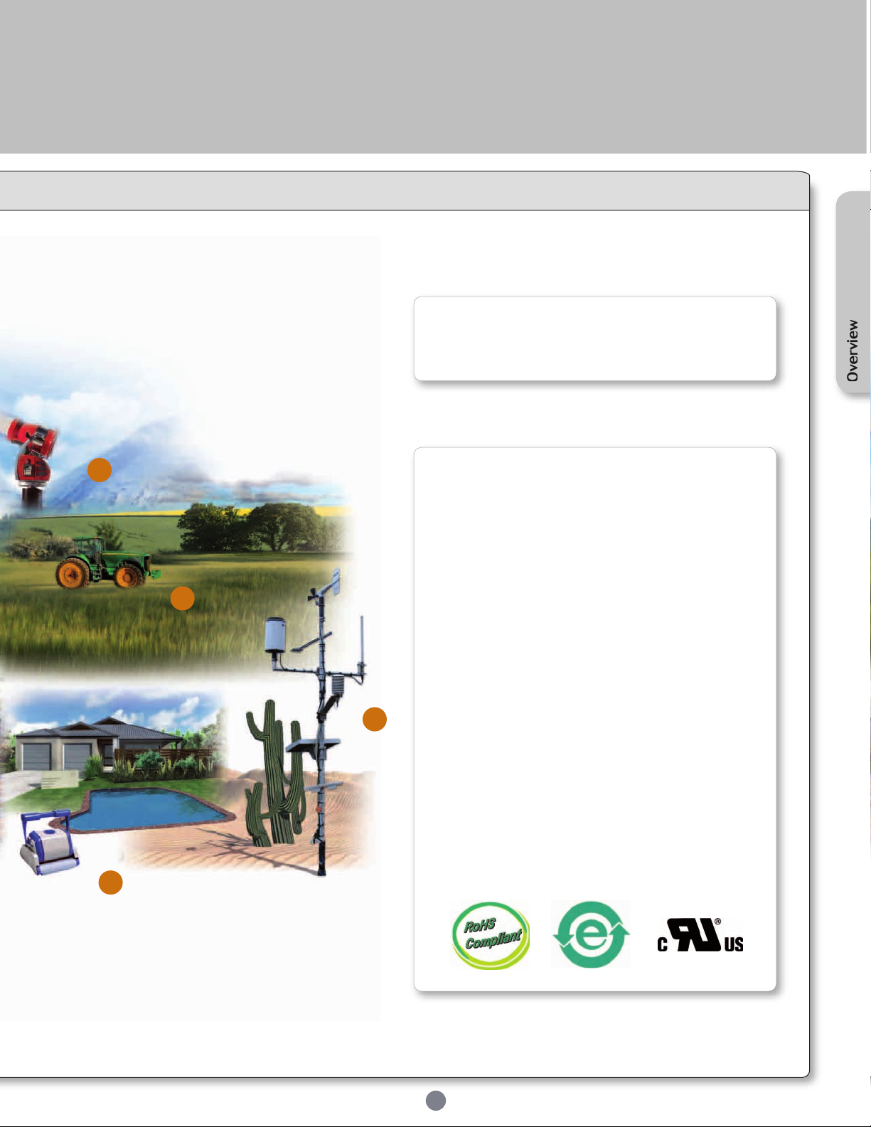
The UTS series is a plastic connector
range but rugged enough to withstand
industrial applications.
The bayonet coupling system makes it simple to use.
With only a 1/3 twist of the coupling ring, connectors are mated
with an audible and sensitive “click”
UTS series is a wide range...
Based on multiple power & signal connectors and offers
everything from box mounted receptacles and cable mounted
plugs to cable mounted in-line and PCB mounted receptacles.
Almost all ways to accommodate wires exist: Crimp, Solder,
Screw termination. We recently added the RJ45 version (Cat5e)
to meet the increasing demand of networking.
Screw termination
version
The philosophy of the UTS series is built around three key elements:
Dynamic IP68/69K
UV Resistant
UL/IEC Compliant
Overview
RJ45 version
UTS series is rated at IP68/69K… even
in dynamic conditions. This means
that it remain sealed even when used
continuously underwater or cleaned using
a high pressure hose and cable is moving.
This extreme level of performance is
achievable with jacketed cable or discrete
wires.
If this same level of performance is
required even when connectors are not
mated, we have UTS Hi Seal; a product
designed to remain watertight if an
environmental cap is not tted or if the
equipment is likely to get wet when cables
have been disconnected.
In most applications, our connectors are
exposed to extreme climatic conditions;
it was therefore key for us to select the
materials best able to cope with the
targeted environment.
Part of our product qualication process
involved subjecting connectors to a
simulated ve years of exposure to various
elements including Temperature, UV and
Humidity.
The results were positive in that there
were no visible signs of weakness, such as
cracking or crazing.
7
The outmost priority for any electrical
installation is to protect personnel from any
shock hazard.
In North America, Underwriters Laboratories insisted that connector manufacturers,
depending of the application, respect
their standards. The UTS series had thus
been qualied and is certied by this
organisation.
In Europe and in Asia, IEC standards are
better known and trusted by end users. Like
its American equivalent, the IEC refers to
safety rules. The UTS series was obviously
designed to respect these rules.
Page 8
UTS Series
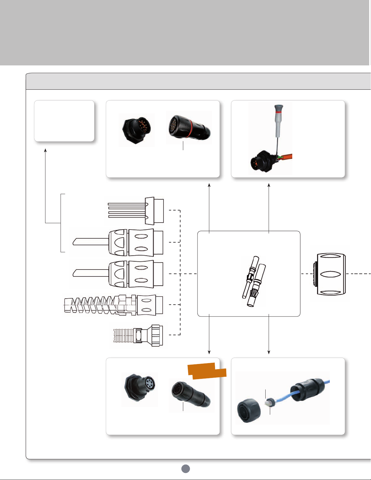
UTS range
UTS discrete
wire sealing
See page 9
UTS Series
Sealed: IP68/69K
UV resistant
UL/IEC compliant
Corrosion-proof
Plastic housing
Crimp
contact
UTS screw
termination
• machined
• stamped and
formed
• coaxial
• fibre optics
Just screw the wires
to the connector !
No special tools
required, use a
standard screwdriver
Screw
termination
contact
UTS Hi seal
Sealed unmated: IP68/69K
MIL-C-26482 compatible
UV resistant
UL/IEC compliant
Solder
contact RJ45
Sealed
Unmated
Corrosion-proof
Plastic housing
8
Plug
UTS RJ45
Standard
RJ45
cordset
Seal to optimize RJ45 cordset
positioning & vibration resistance
Page 9
UTS Series
overview
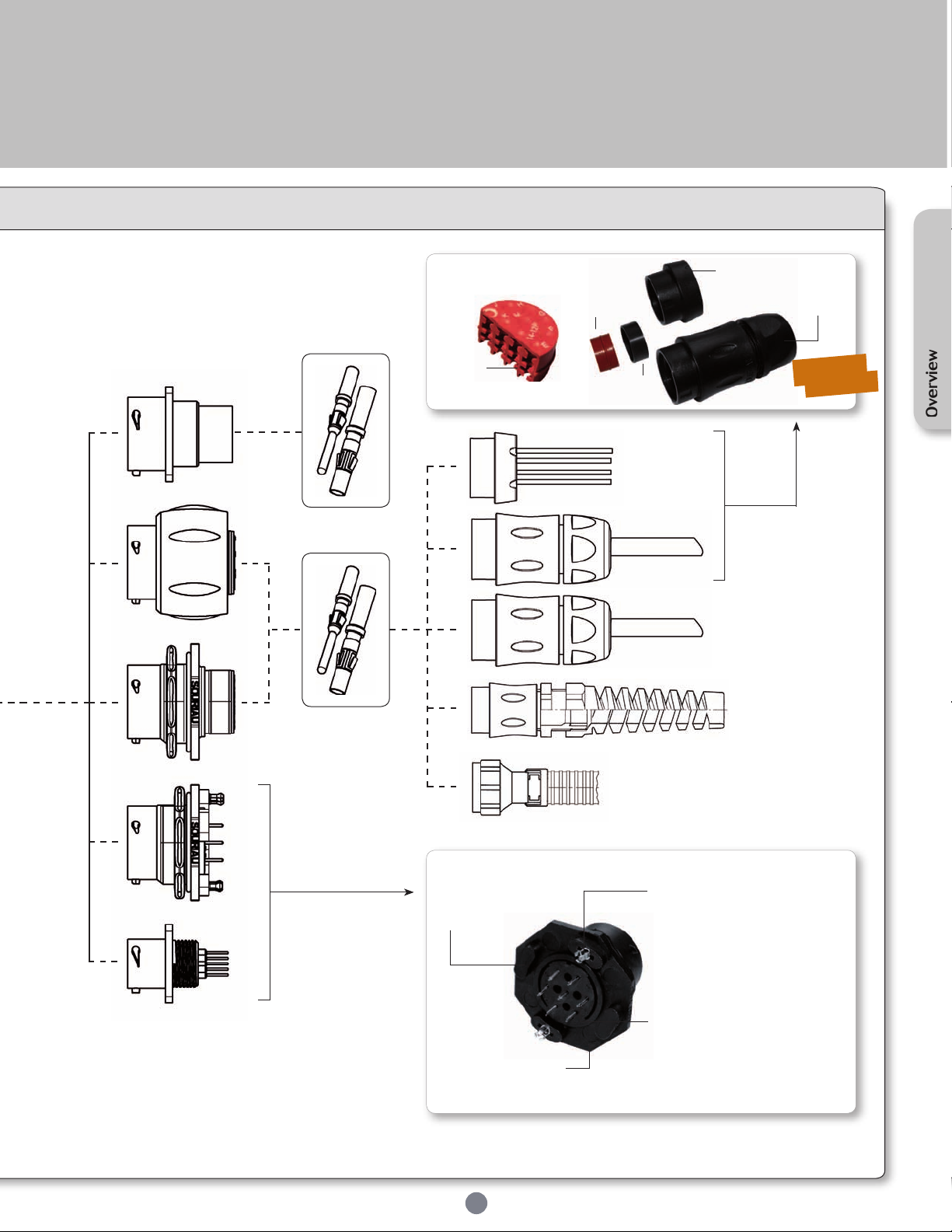
UTS discrete wire sealing
Grommet
No ller
plug needed
Containment
ring
Backnut
or
Easy handling
backshell
Double
Sealing
Overview
Receptacles
UTS PCB contacts
Stand-offs to allow
cleaning after
soldering
Low prole housing to
limit space between
panel and PCB
9
Metal hold down clips
- to lock the connector easily on
the PCB and to release stress on
solder joints
- suitable for soldering in a
metalised hole
Pre-assembled PCB contacts
- machined or stamped versions
available
- different solder tails lengths
possible
- different plating options
Page 10
UTS Series
Mechanical
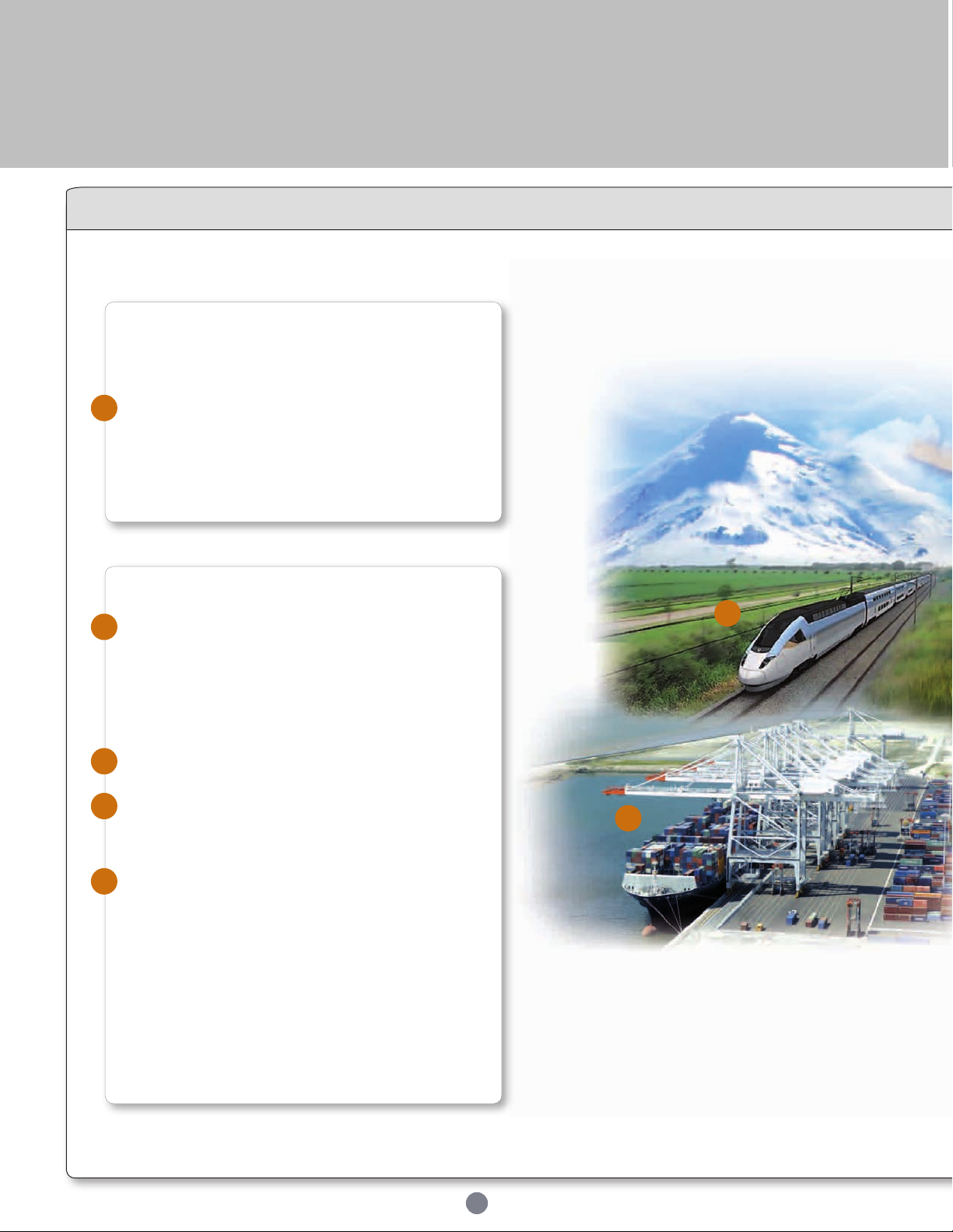
• Durability:
250 matings & unmatings per MIL-C-26482
• Vibration resistance (all UTS versions except UTS Screw
1
termination contacts & UTS RJ45):
Sinusoidal vibrations per CEI 60512-4 - from 10 to 2000 Hz
• Thermal shock (all UTS versions except UTS RJ45):
5 cycles 30 min. from -40°C to 105°C per MIL-STD1344
method 1003
General technical
Environmental
• Operating temperature:
2
from -40°C to +105°C
40/100/21 per NFF 61-030
• Flammability rating:
UL94-V0 (all UTS except the Hi seal) - see page 60
UL94-HB (UTS Hi seal only) - see page 60
I2F3/I3F2 per NFF 61-030
• Salt spray:
3
≥500 hours
• UV resistant:
4
No mechanical degradation or important variation of colour
after 5 years of exposure in natural environment (equivalence
exposure to sun and moisture as per ISO4892)
• Sealing:
5
- UTS Standard: IP68/IP69K (mated)
- UTS Hi seal: IP68/IP69K (mated and unmated)
- UTS Discrete wire sealing: IP67/69K (up to IP68 with easy
handling backshell)
- UTS Screw termination contacts: IP68/I P69K
- UTS RJ45: IP65
Note: IPx8: 1m underwater during 1 week
• Fluid resistance:
- Gasoil
- Mineral oil
- Acid bath
- Basic bath
1
3
10
Page 11
UTS Series
characteristics
Electrical
• See pages 14 to 20
Overview
2
1
4
Material
• Body connector + Backshell:
Thermoplastic
• Insert:
- UTS Standard, UTS Discrete wire sealing, UTS Screw
termination contacts & UTS RJ45:
Thermoplastic
- UTS Hi seal handsolder & UTS Hi seal with PC tails contacts:
Elastomer
• Contacts:
See page 39
• Nut:
Metal
• Halogen free
• RoHS compliant & conform to the Chinese standard
SJ/T1166-2006 (Chinese RoHS equivalent)
• In accordance with:
- UL 1977:
Certicat ECBT2
File number: E169916
- CSA C22.2 n°182.3:
Certicat ECBT8
File number: E169916
5
11
Page 12
UTS Series
Contact
quantity
Shell
size
Wire dimension & Contacts size
AWG 22 to 12
0.13 to 4 mm²
AWG 26 to 18
0.13 to 0.93 mm²
AWG 30 to14
0.05 to 2.5 mm²
AWG 16 to 8
1.5 to 10 mm²
Contact #12 / Ø2.4mm Contact #20 / Ø1mm Contact #16 / Ø1.6mm Contact #8 / Ø3.6mm
2
8
8E2 (Solder)
8D2 (PCB)
12
12E2 (Solder)
12D2 (PCB)
2 + PE 10 103 (Crimp) 142G1 (Crimp)
3
8
8E3, 8E3A, 8E98, 8E33 (Solder)
8D3, 8D3A, 8D98, 8D33 (PCB)
12
12E3 (Solder)
12D3 (PCB)
3 + PE 12
124 (Crimp)
124 (Screw) *
4
8
8E4 (Solder)
8D4 (PCB)
10 102W2 (Crimp, 2#20 + 2#12)
10 104 (Crimp)
5 14 145 (Crimp)
6 10
106 (Crimp)
10E6,10E98 (Solder)
10D6,10D98 (PCB)
103W3 (Crimp, 3#20 + 3#16)
6 + PE 14
147 (Crimp)
147 (Screw) *
7 10
10E7 (Solder)
10D7 (PCB)
8 12
12E8 (Solder)
12D8 (PCB)
128 (Crimp)
10 12
1210 (Crimp)
12E10 (Solder)
12D10 (PCB)
11 18
18E11 (Solder)
18D11 (PCB)
12 14
1412 (Crimp)
14E12 (Solder, 8#20 + 4#16)
14D12 (PCB, 8#20 + 4#16)
14 12
12E14 (Solder)
12D14 (PCB)
15 14 1415 (Crimp, 14#20 + 1#16)
19 14
1419 (Crimp)
14E19 (Solder)
14D19 (PCB)
23 18
1823 (Crimp)
18E23 (Solder)
18D23 (PCB)
30 18
18E30 (Solder, 29#20 + 1#16)
18D30 (PCB, 29#20 + 1#16)
32 18
1832 (Crimp)
18E32 (Solder)
18D32 (PCB)
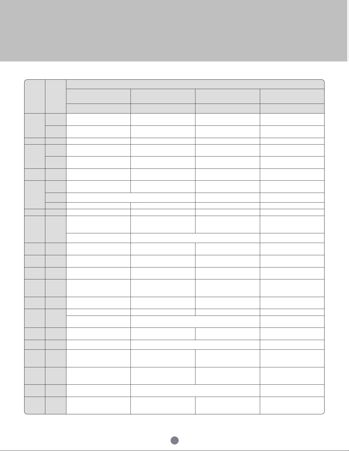
UTS Layout Guide
* AWG 20 to 14, 0.5 to 2.5 mm². Contact #16.
Note: PE=protective earth
12
Page 13
UTS Series
Contact layouts
Size 8
8E2
8D2
□
2 Ø1 (#20) 3 Ø1 (#20) 3 Ø1 (#20)
8E3
8D3
□
8E3A/8E98
8D3A/8D98
Size 10
102W2
■
○
2 Ø1.0 (#20)
103
(2+PE)
3 Ø1.6 (#16)
103W3
■
○
3 Ø1.6 (#16)
3 Ø1.0 (#20)
Size 12
12E2
12D2
□ □
12E3
12D3
124
(3+PE)
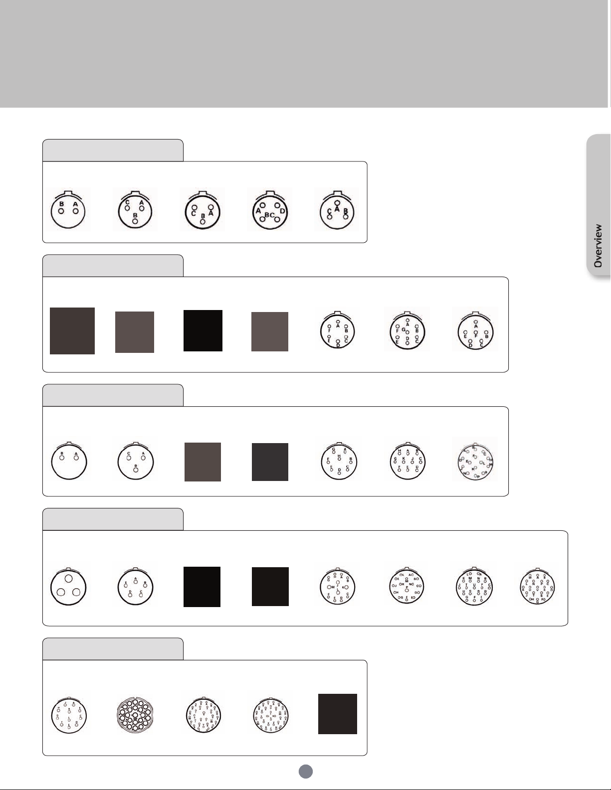
UTS layouts:
8E4
8D4
□
4 Ø1 (#20) 3 Ø1 (#20)
□ □
104
■
○
▲
128
■
○
●
▲
8E33
8D33
= UTS standard version (Ex: 1210)
- -
= UTS Hi seal + Solder (Ex: 12E10)
- E = UTS Hi seal + PCB (Ex: 12D10)
- D -
■
= UTS standard version
□
= UTS Hi seal version
= UTS discrete wire sealing version
▲
= UTS with screw contact termination
●
= In-Line version
○
Overview
106
10E6
10D6
■
○
■
□
10E7
10D7
10E98
10D98
□
□
○
6 Ø1 (#20) 7 Ø1 (#20) 6 Ø1 (#20) 4 Ø1.6 (#16)2 Ø2.4 (#12)
12E8
12D8
■
□ ■
○
1210
12E10
12D10
12E14
12D14
□
□
○
2 Ø1.6 (#16)
142G1
(2+PE)
3 Ø3.6 (#8)
18E11
18D11
11 Ø1.6 (#16)
3 Ø1.6 (#16) 8 Ø1 (#20) 10 Ø1 (#20)
4 Ø1.6 (#16)
8 Ø1.6 (#16)
Size 14
□
14E5
14D5
□ ■
5 Ø1.6 (#16)
147
(6+PE)
7 Ø1.6 (#16)
○
▲
●
1412
12 Ø1.6 (#16)
■
○
▲
14E12
14D12
□ □ □■
8 Ø1 (#20)
4 Ø1.6 (#16)
Size 18
1823
18E23
□ ■
18D33
23 Ø1.6 (#16)
18E30
18D30
□ ■
○
29 Ø1 (#20)
1 Ø1.6 (#16)
1832
18E32
18D32
32 Ø1 (#20)
RJ45
■
□
○
13
1415
14 Ø1 (#20)
1 Ø1.6 (#16)
14 Ø1 (#20)
14E18
14D18
18 Ø1 (#20)
1419
14E19
14D19
□
○
19 Ø1 (#20)
Page 14
UTS Series
De-rating curves
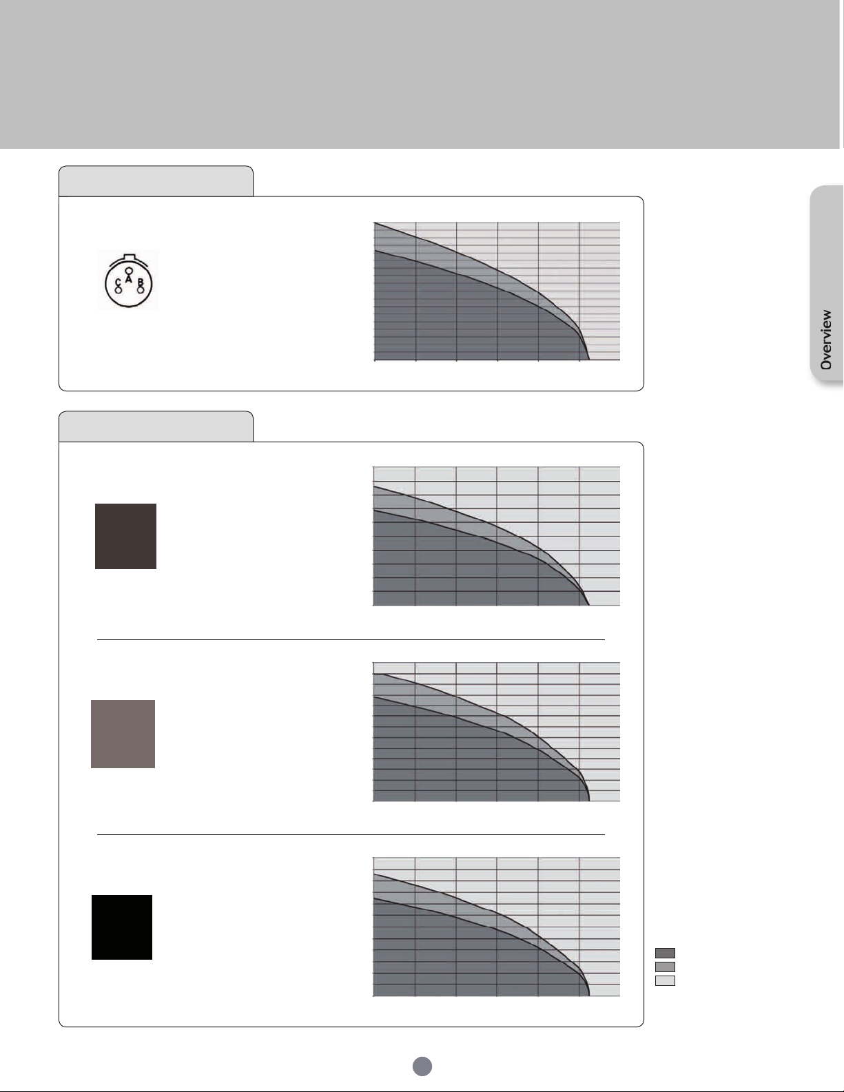
Size 8
8E2
8D2
□
Contacts :
2 Ø 1 (#20)
8E3
8D3
□
Contacts :
3 Ø 1 (#20)
8E3A/8E98
8D3A/8D98
□
Contacts :
3 Ø 1 (#20)
8E4
8D4
□
Contacts :
4 Ø 1 (#20)
UL
7A 250V UL94 HB
CSA
7A 250V UL94 HB
IEC
7A 63V 2.5kV 3
UL
7A 250V UL94 HB
CSA
7A 250V UL94 HB
IEC
7A 40V 2.5kV 3
UL
7A 250V UL94 HB
CSA
7A 250V UL94 HB
IEC
7A 40V 2.5kV 3
UL
7A 250V UL94 HB
CSA
7A 250V UL94 HB
IEC
7A 40V 2.5kV 3
UTS Hi seal 8E2 8D2
18
16
14
12
10
8
Current (A)
6
4
2
0
0 20 40 60 80 100 120
18
16
14
12
10
8
Current (A)
6
4
2
0
0 20 40 60 80 100 120
18
16
14
12
10
8
Current (A)
6
4
2
0
0 20 40 60 80 100 120
18
16
14
12
10
8
Current (A)
6
4
2
0
0 20 40 60 80 100 120
Ambient Operating Temperature (°C)
UTS Hi seal 8E3 8D3
Ambient Operating Temperature (°C)
UTS Hi seal 8E3A/98 8D3A/98
Ambient Operating Temperature (°C)
UTS Hi seal 8E4 8D4
Ambient Operating Temperature (°C)
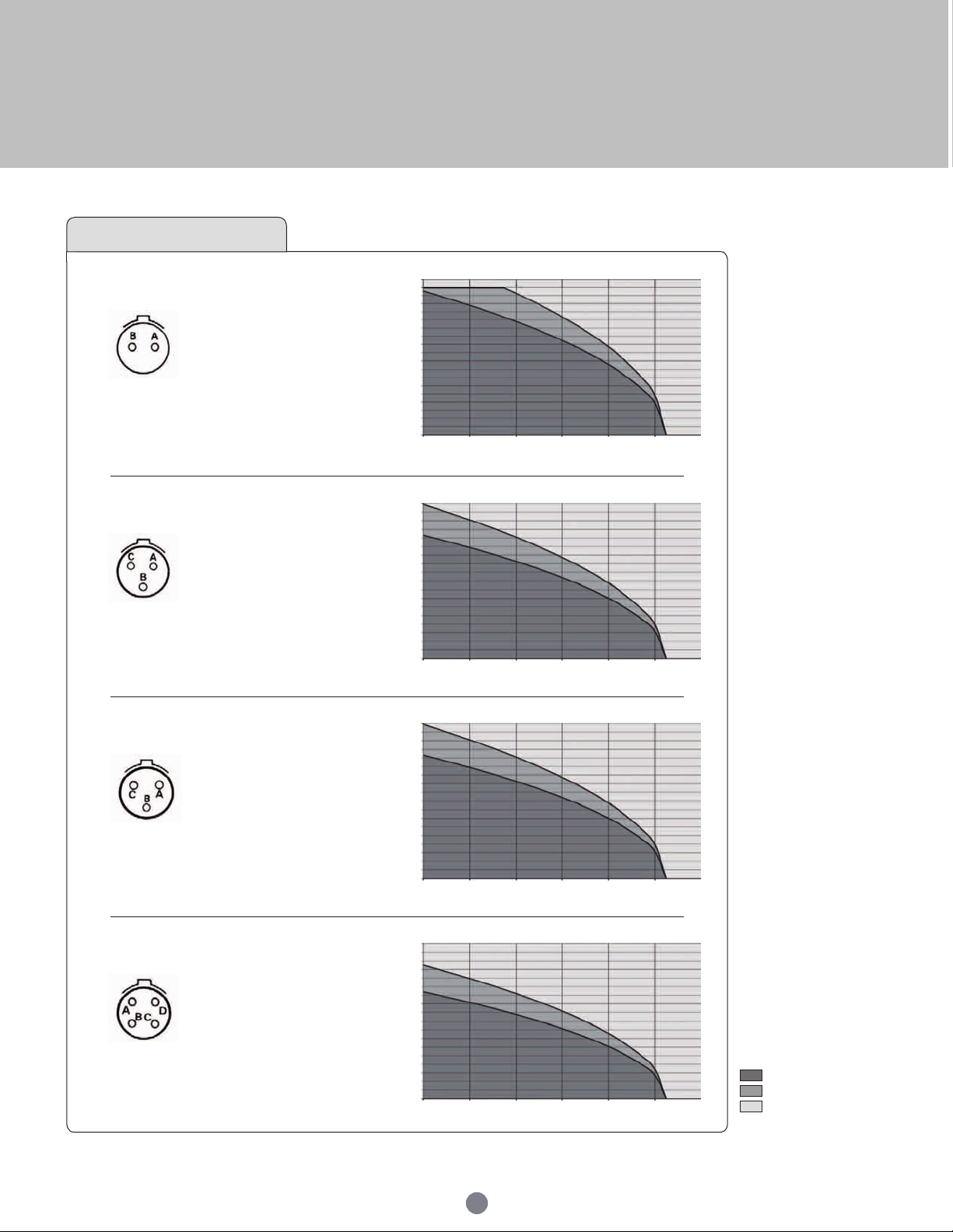
Test conditions
Contact used:
Machined contacts
Wires used:
0.518mm² for #20 contacts
1.31mm² for #16 contacts
3.31mm² for #12 contacts
8.37mm² for #8 contacts
Layouts
UTS standard version
■
UTS discrete wire sealing
▲
version
In-Line version
○
UTS Hi seal version
□
UTS with screw contact
●
termination
Derating curve
Current use
Limited use
Not recommended use
14
Page 15
UTS Series
Size 8
8E33
8D33
Contacts :
3 Ø 1 (#20)
Size 10
102W2
Contacts :
2 Ø2.4 (#12)
2 Ø1.0 (#20)
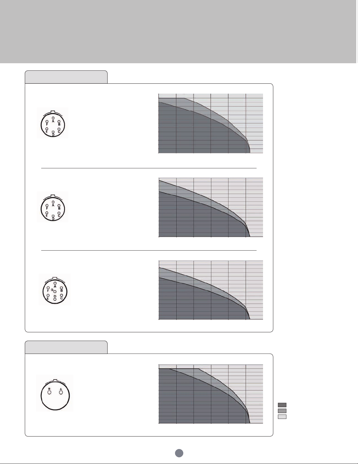
18
□
UL
7A 250V UL94 HB
CSA
7A 250V UL94 HB
IEC
7A 100V 2.5kV 3
■
○
UL
20A 500V UL94 V-0
CSA
18A 500V UL94 V-0
IEC
25A 200V 3kV 3
Temperature elevation: 50°C
16
14
12
10
8
Current (A)
6
4
2
0
0 20 40 60 80 100 120
50
45
40
35
30
25
20
Current (A)
15
10
5
0
0 20 40 60 80 100 120
UTS Hi seal 8E33 8D33
Ambient Operating Temperature (°C)
UTS 102W2
Ambient Operating Temperature (°C)
Overview
103
(2+PE)
Contacts* :
3 Ø 1.6 (#16)
104
Contacts :
4 Ø 1.6 (#16)
▲
UTS 103
30
■
○
UL
10A 500V UL94 V-0
CSA
7A 500V UL94 V-0
IEC
16A 320V 4kV 3
Temperature elevation: 50°C
■
○
UL
10A 500V UL94 V-0
CSA
7A 500V UL94 V-0
IEC
16A 200V 3kV 3
28
25
23
20
18
15
13
Current (A)
10
8
5
3
0
0 20 40 60 80 100 120
30
28
25
23
20
18
15
13
Current (A)
10
8
5
3
0
0 20 40 60 80 100 120
Ambient Operating Temperature (°C)
UTS 104
Ambient Operating Temperature (°C)
Test conditions
Contact used:
Machined contacts
Wires used:
0.518mm² for #20 contacts
1.31mm² for #16 contacts
3.31mm² for #12 contacts
8.37mm² for #8 contacts
Layouts
UTS standard version
■
UTS discrete wire sealing
▲
version
In-Line version
○
UTS Hi seal version
□
UTS with screw contact
●
termination
Derating curve
Current use
Limited use
Not recommended use
15
Page 16
UTS Series
Size 10
106
■
□
○
Contacts :
6 Ø 1 (#20)
UL
5A 250V UL94 V-0
CSA
4A 250V UL94 V-0
IEC
6A 40V 1.5kV 3
UTS 106
12
10
8
6
Current (A)
4
2
0
0 20 40 60 80 100 120
Ambient Operating Temperature (°C)
10E6
10D6
Contacts :
6 Ø 1 (#20)
10E7
10D7
Contacts :
7 Ø 1 (#20)
Size 12
12E2
12D2
Contacts :
2 Ø 1.6 (#16)
UTS Hi seal 10E6 10D6
14
■
□
○
UL
6A 250V UL94 HB
CSA
6A 250V UL94 HB
IEC
10A 100V 2.5kV 3
12
10
8
6
Current (A)
4
2
0
0 20 40 60 80 100 120
Ambient Operating Temperature (°C)
UTS Hi seal 10E7 10D7
14
□
UL
6A 250V UL94 HB
CSA
6A 250V UL94 HB
IEC
7A 100V 2.5kV 3
12
10
8
6
Current (A)
4
2
0
0 20 40 60 80 100 120
Ambient Operating Temperature (°C)
Test conditions
Contact used:
Machined contacts
Wires used:
0.518mm² for #20 contacts
1.31mm² for #16 contacts
3.31mm² for #12 contacts
8.37mm² for #8 contacts
Layouts
UTS standard version
■
UTS discrete wire sealing
UTS Hi seal 12E2 12D2
30
□
UL
13A 650V UL94 HB
20
CSA
13A 650V UL94 HB
Current (A)
10
IEC
16A 160V 3kV 3
0
0 20 40 60 80 100 120
Ambient Operating Temperature (°C)
▲
version
In-Line version
○
UTS Hi seal version
□
UTS with screw contact
●
termination
Derating curve
Current use
Limited use
Not recommended use
16
Page 17
UTS Series
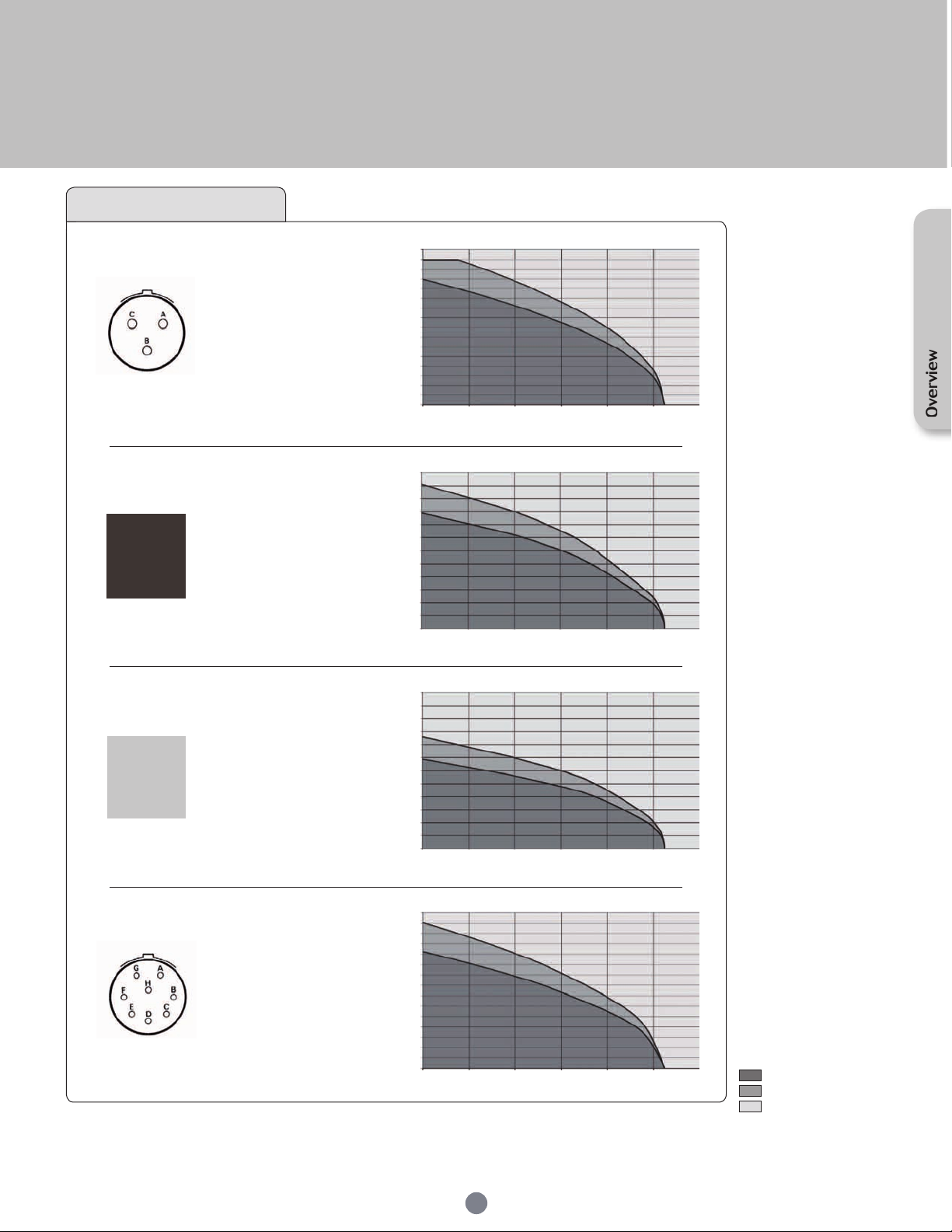
Size 12
12E3
12D3
Contacts :
3 Ø 1.6 (#16)
124
(3+PE)
Contacts* :
4 Ø 1.6 (#16)
128
Contacts :
8 Ø 1.6 (#16)
▲
UL
□
13A 650V UL94 HB
CSA
13A 650V UL94 HB
IEC
16A 160V 3kV 3
UL
■
10A 500V UL94 V-0
○
●
CSA
7A 500V UL94 V-0
IEC
16A 400V 4kV 3
Temperature elevation: 50°C
UL
■
10A 500V UL94 V-0
○
CSA
7A 500V UL94 V-0
IEC
10A 80V 2.5kV 3
UTS Hi seal 12E3 12D3
30
20
Current (A)
10
0
0 20 40 60 80 100 120
30
28
25
23
20
18
15
13
Current (A)
10
8
5
3
0
0 20 40 60 80 100 120
30
28
25
23
20
18
15
13
Current (A)
10
8
5
3
0
0 20 40 60 80 100 120
Ambient Operating Temperature (°C)
UTS 124
Ambient Operating Temperature (°C)
UTS 128
Ambient Operating Temperature (°C)
Test conditions
Contact used:
Machined contacts
Wires used:
0.518mm² for #20 contacts
1.31mm² for #16 contacts
3.31mm² for #12 contacts
8.37mm² for #8 contacts
Overview
12E8
12D8
Contacts :
8 Ø 1 (#20)
UL
□
4.5A 250V UL94 HB
CSA
4.5A 250V UL94 HB
IEC
7A 100V 2.5kV 3
UTS Hi seal 12E8 12D8
14
12
10
8
6
Current (A)
4
2
0
0 20 40 60 80 100 120
Ambient Operating Temperature (°C)
17
Layouts
UTS standard version
■
UTS discrete wire sealing
▲
version
In-Line version
○
UTS Hi seal version
□
UTS with screw contact
●
termination
Derating curve
Current use
Limited use
Not recommended use
Page 18
UTS Series
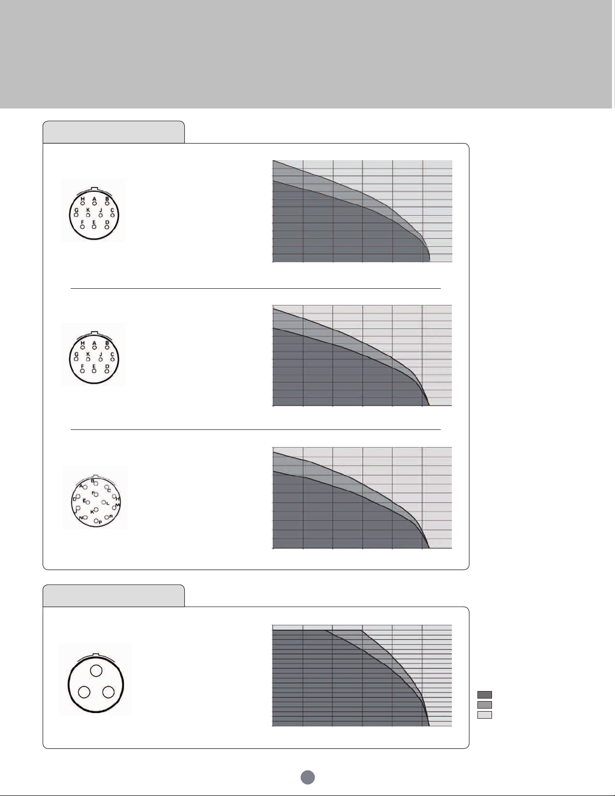
Size 12
1210
Contacts :
10 Ø 1 (#20)
12E10
12D10
Contacts :
10 Ø 1 (#20)
12E14
12D14
Contacts :
14 Ø 1 (#20)
UTS 1210
12
■
□
○
UL
5A 250V UL94 V-0
CSA
4A 250V UL94 V-0
IEC
6A 40V 1.5kV 3
10
8
6
Current (A)
4
2
0
0 20 40 60 80 100 120
Ambient Operating Temperature (°C)
UTS Hi seal 12E10 12D10
12
■
□
○
UL
4.5A 250V UL94 HB
CSA
4.5A 250V UL94 HB
IEC
7A 100V 2.5kV 3
10
8
6
Current (A)
4
2
0
0 20 40 60 80 100 120
Ambient Operating Temperature (°C)
UTS Hi seal 12E14 12D14
10
□
UL
4.5A 250V UL94 HB
CSA
4.5A 250V UL94 HB
IEC
7A 32V 2.5kV 3
8
6
4
Current (A)
2
0
0 20 40 60 80 100 120
Ambient Operating Temperature (°C)
Test conditions
Contact used:
Machined contacts
Wires used:
0.518mm² for #20 contacts
1.31mm² for #16 contacts
3.31mm² for #12 contacts
8.37mm² for #8 contacts
Size 14
142G1
Contacts :
3 Ø 3.6 (#8)
UL
44A 600V UL94 V-0
□
CSA
30A 600V UL94 V-0
IEC
42A 230V 4kV 3
UTS 142G1
50
45
40
35
30
25
20
Current (A)
15
10
5
0
0 20 40 60 80 100 120
Ambient Operating Temperature (°C)
18
Layouts
UTS standard version
■
UTS discrete wire sealing
▲
version
In-Line version
○
UTS Hi seal version
□
UTS with screw contact
●
termination
Derating curve
Current use
Limited use
Not recommended use
Page 19
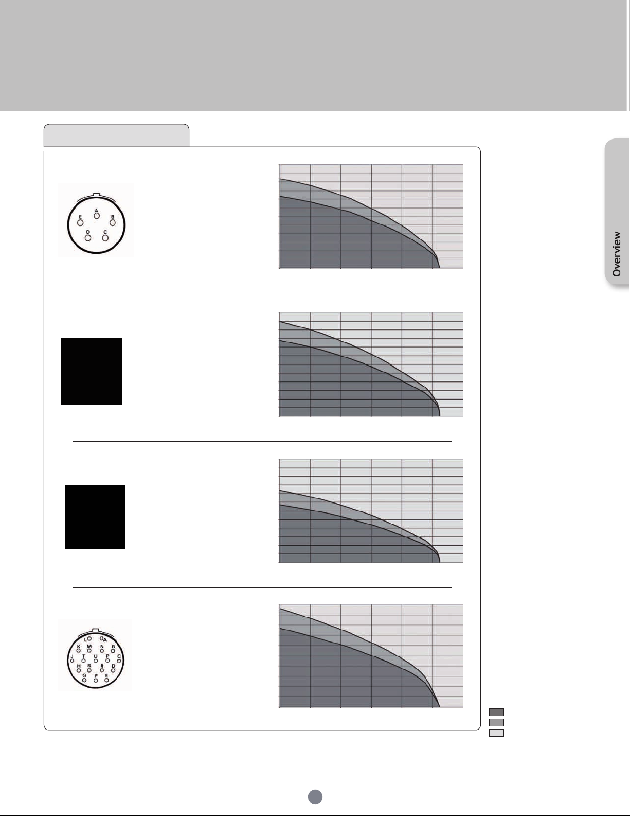
UTS Series
Size 14
14E5
14D5
Contacts :
5 Ø 1.6 (#16)
147
(6+PE)
Contacts* :
7 Ø 1.6 (#16)
1412
Contacts :
12 Ø 1.6 (#16)
▲
■
○
▲
30
28
UL
□
12A 650V UL94 HB
CSA
12A 650V UL94 HB
IEC
16A 160V 3kV 3
■
○
●
UL
10A 500V UL94 V-0
CSA
7A 500V UL94 V-0
IEC
16A 400V 4kV 3
Temperature elevation: 50°C
UL
10A 500V UL94 V-0
CSA
7A 500V UL94 V-0
IEC
10A 80V 2.5kV 3
25
23
20
18
15
13
Current (A)
10
8
5
3
0
0 20 40 60 80 100 120
30
28
25
23
20
18
15
13
Current (A)
10
8
5
3
0
0 20 40 60 80 100 120
30
28
25
23
20
18
15
13
Current (A)
10
8
5
3
0
0 20 40 60 80 100 120
UTS Hi seal 14E5 14D5
Ambient Operating Temperature (°C)
UTS 147
Ambient Operating Temperature (°C)
UTS 1412
Ambient Operating Temperature (°C)
Test conditions
Contact used:
Machined contacts
Wires used:
0.518mm² for #20 contacts
1.31mm² for #16 contacts
3.31mm² for #12 contacts
8.37mm² for #8 contacts
Overview
14E18
14D18
Contacts :
18 Ø 1 (#20)
UL
□
4A 250V UL94 HB
CSA
4A 250V UL94 HB
IEC
7A 100V 2.5kV 3
10
8
6
4
Current (A)
2
0
0 20 40 60 80 100 120
UTS Hi seal 14E18 14D18
Ambient Operating Temperature (°C)
19
Layouts
UTS standard version
■
UTS discrete wire sealing
▲
version
In-Line version
○
UTS Hi seal version
□
UTS with screw contact
●
termination
Derating curve
Current use
Limited use
Not recommended use
Page 20
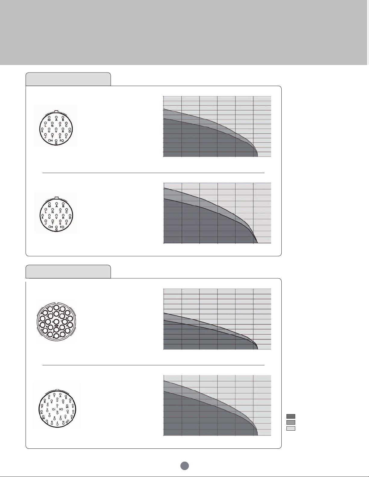
UTS Series
Size 14
1419
Contacts :
19 Ø 1 (#20)
■
□
○
UL
5A 250V UL94 V-0
CSA
4A 250V UL94 V-0
IEC
4A 40V 1.5kV 3
UTS 1419
12
10
8
6
Current (A)
4
2
0
0 20 40 60 80 100 120
Ambient Operating Temperature (°C)
14E19
14D19
Contacts :
19 Ø 1 (#20)
Size 18
1823
Contacts :
23 Ø 1.6 (#16)
1832
Contacts :
32 Ø 1 (#20)
UTS Hi seal 14E19 14D19
■
UL
□
4A 250V UL94 HB
○
10
8
6
CSA
4A 250V UL94 HB
IEC
7A 100V 2.5kV 3
■
○
UL
10A 500V UL94 V-0
CSA
7A 500V UL94 V-0
IEC
10A 80V 2.5kV 3
■
UL
□
5A 250V UL94 V-0
○
CSA
4A 250V UL94 V-0
IEC
3A 32V 1.5kV 3
4
Current (A)
2
0
0 20 40 60 80 100 120
30
28
25
23
20
18
15
13
Current (A)
10
8
5
3
0
0 20 40 60 80 100 120
10
8
6
4
Current (A)
2
0
0 20 40 60 80 100 120
Ambient Operating Temperature (°C)
UTS 1823
Ambient Operating Temperature (°C)
UTS 1832
Ambient Operating Temperature (°C)
Test conditions
Contact used:
Machined contacts
Wires used:
0.518mm² for #20 contacts
1.31mm² for #16 contacts
3.31mm² for #12 contacts
8.37mm² for #8 contacts
Layouts
UTS standard version
■
UTS discrete wire sealing
▲
version
In-Line version
○
UTS Hi seal version
□
UTS with screw contact
●
termination
Derating curve
Current use
Limited use
Not recommended use
20
Page 21
Overview
21
Page 22

Page 23
UTS Series
Mechanics
UTS plug cable gland backshell .................................................................................................
UTS square ange receptacle .....................................................................................................
UTS jam nut receptacle with accessories ................................................................................
PCB version: nominal length out ................................................................................................
UTS in line receptacle with accessories ..................................................................................
Accessories ........................................................................................................................................
Cable assembly .................................................................................................................................
24
26
28
30
32
34
36
Page 24
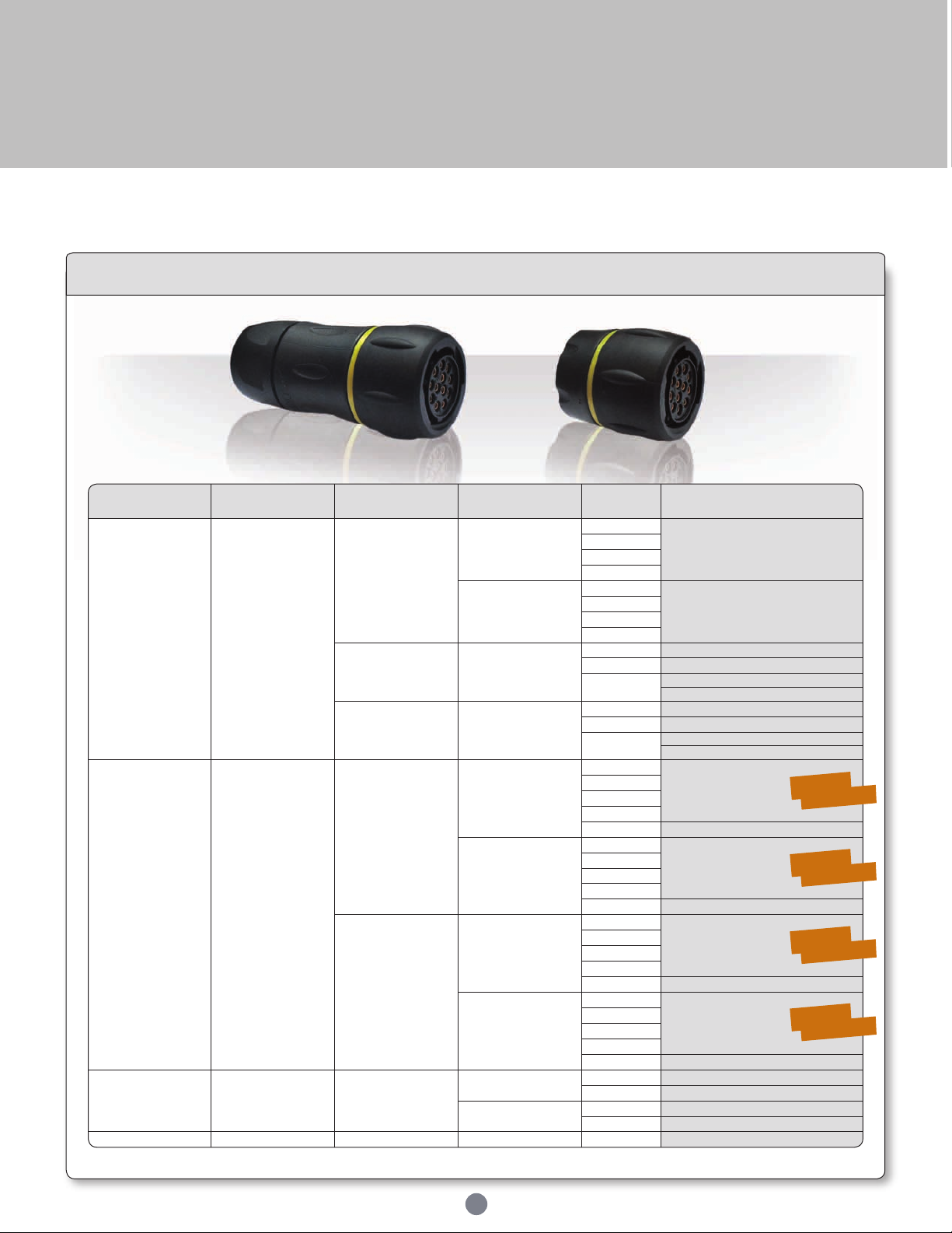
UTS Series
Contact type Connector type Termination Contact sex Shell size Part number
Crimp
contacts supply
separately
UTS standard
Cable gland
Male
10
UTS6JC - - P
12
14
18
Female
10
UTS6JC - - S
12
14
18
Nut and grommet Female
10 UTS6GN104S
12 UTS6GN128S
14
UTS6GN147S
UTS6GN1412S
Cable gland
and grommet
Female
10 UTS6GJC104S
12 UTS6GJC128S
14
UTS6GJC147S
UTS6GJC1412S
Solder
contacts loaded
Hi seal
No backshell
Male
8
UTS6 - E - P
10
12
14
18 On demand
Female
8
UTS6 - E - S
10
12
14
18 On demand
Cable gland
Male
8
UTS6JC - E - P
10
12
14
18 On demand
Female
8
UTS6JC - E - S
10
12
14
18 On demand
Screw
contacts loaded
UTS standard Cable gland
Male
12 UTS6JC124PSCR
14 UTS6JC147PSCR
Female
12 UTS6JC124SSCR
14 UTS6JC147SSCR
RJ45 UTS standard Cable gland - 18 UTS6JC18RJN
Mechanics
UTS plug cable gland backshell
Part number
For coding " - - " see p.6 and UTS layout guide p.12.
24
Sealed
Unmated
Sealed
Unmated
Sealed
Unmated
Sealed
Unmated
Page 25
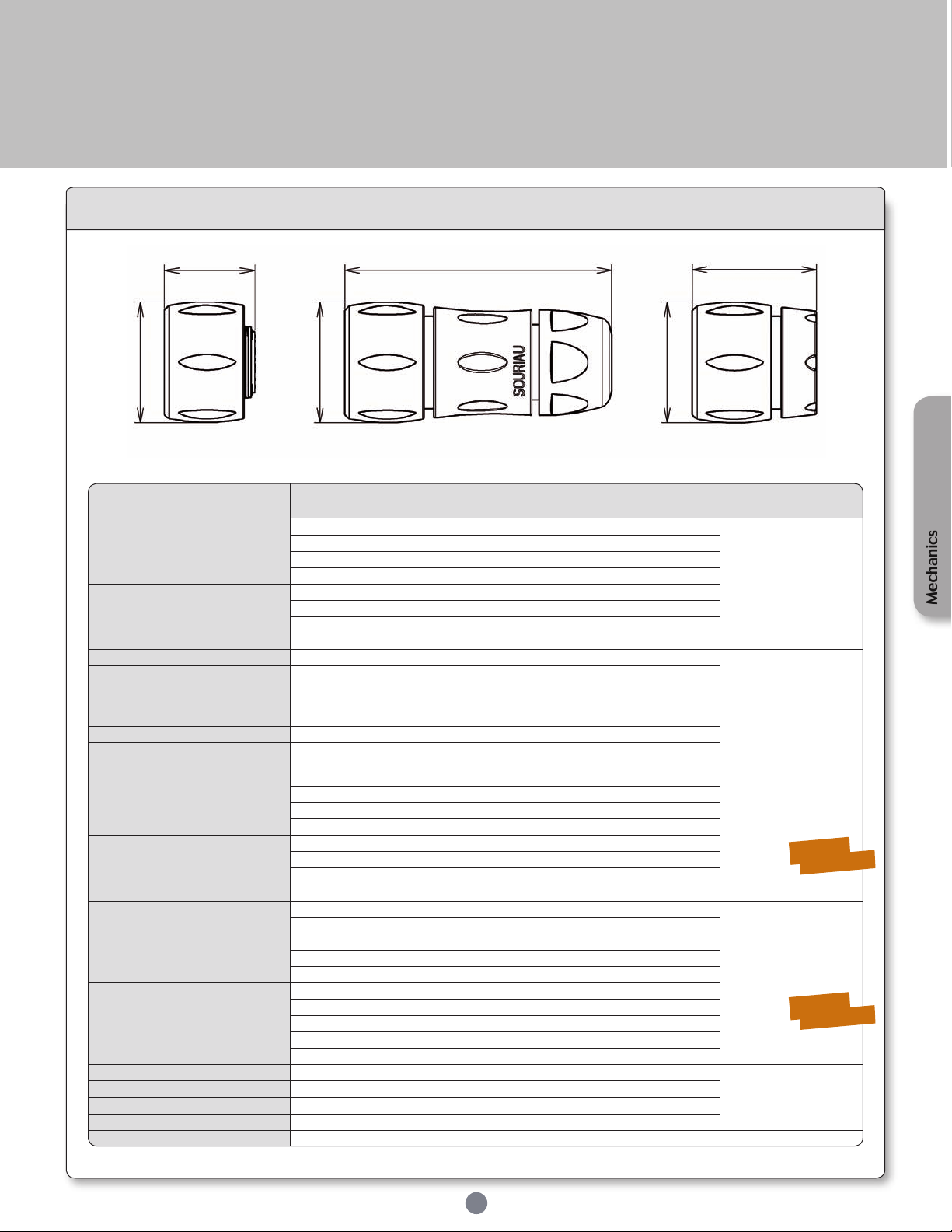
UTS Series
Part number Shell size
L
(total length)
ØA Figure
UTS6JC - - P
10 63.2 26.7
Fig. 2
12 66.7 30.2
14 71.5 35.1
18 81.3 42
UTS6JC - - S
10 63.2 26.7
12 66.7 30.2
14 71.5 35.1
18 81.3 42
UTS6GN104S 10 32 26.2
Fig. 3
UTS6GN128S 12 32.3 29.7
UTS6GN147S
14 32 34.6
UTS6GN1412S
UTS6GJC104S 10 61.5 26.2
Fig. 2
UTS6GJC128S 12 64.5 29.7
UTS6GJC147S
14 70 34.6
UTS6GJC1412S
UTS6 - E - P
8 21.3 22.5
Fig. 1
10 23.6 26.7
12 23.6 30.2
14 23.6 35.1
UTS6 - E - S
8 21.3 22.5
10 23.6 26.7
12 23.6 30.2
14 23.6 35.1
UTS6JC - E - P
8 54 22.5
Fig. 2
10 63.2 26.7
12 66.7 30.2
14 71.5 35.1
18 81.3 42
UTS6JC - E - S
8 54 22.5
10 63.2 26.7
12 66.7 30.2
14 71.5 35.1
18 81.3 42
UTS6JC124PSCR 12 66.7 29.7
Fig. 2
UTS6JC147PSCR 14 71.5 34.6
UTS6JC124SSCR 12 66.7 29.7
UTS6JC147SSCR 14 71.5 34.6
UTS6JC18RJN 18 81.3 42 Fig. 2
L L L
Dimensions
ØA
Fig. 1 Fig. 2 Fig. 3
For coding " - - " see p.6 and UTS layout guide p.12.
ØA
25
ØA
Mechanics
Sealed
Unmated
Sealed
Unmated
Note : all dimensions are in mm
Page 26
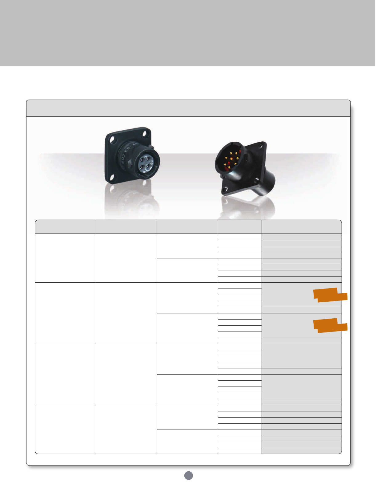
UTS Series
Contact type Connector type Contact sex Shell size Part number
Crimp
contacts supply
separately
UTS standard
Male
10 UTS0104P
12 UTS0128P
14 UTS01412P
18 UTS01823P
Female
10 UTS0104S
12 UTS0128S
14 UTS01412S
18 UTS01823S
Solder
contacts loaded
Hi seal
Male
8
UTS0 - E - P
10
12
14
18 On demand
Female
8
UTS0 - E - S
10
12
14
18 On demand
PCB
contacts loaded
Hi seal
Male
8
UTS0 - D - P
10
12
14
18 On demand
Female
8
UTS0 - D - S
10
12
14
18 On demand
PCB
contacts supply
separately
UTS standard
Male
10 UTS0104P
12 UTS0128P
14 UTS01412P
18 UTS01823P
Female
10 UTS0104S
12 UTS0128S
14 UTS01412S
18 UTS01823S
Mechanics
UTS square flange receptacle
Part number
26
For coding " - - " see p.6 and UTS layout guide p.12.
Sealed
Unmated
Sealed
Unmated
Page 27
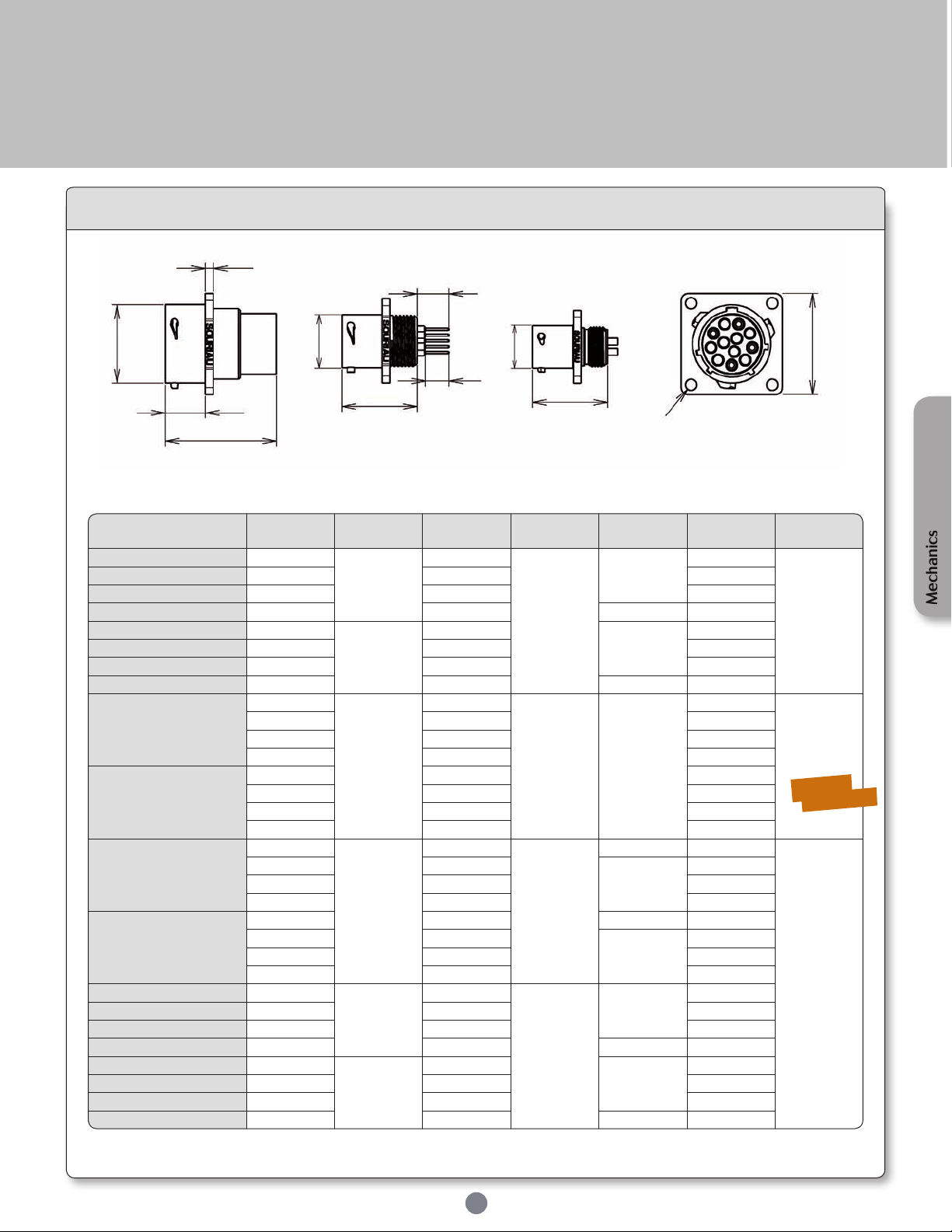
UTS Series
Part number Shell size
L
(total length)
ØA B C D Figure
UTS0104P 10
31.7
15
11.35
2.3
23.8
Fig. 1
UTS0128P 12 19 26.2
UTS01412P 14 22.2 28.6
UTS01823P 18 28.5 2.5 33.3
UTS0104S 10
24.2
15
2.3
23.8
UTS0128S 12 19 26.2
UTS01412S 14 22.2 28.6
UTS01823S 18 28.5 2.5 33.3
UTS0 - E - P
8
21.5
12
11.35 2.3
21
Fig. 3
10 15 23.8
12 19 26.2
14 22.2 28.6
UTS0 - E - S
8 12 21
10 15 23.8
12 19 26.2
14 22.2 28.6
UTS0 - D - P
8
21.5
11.9
11.3
2.3 21
Fig. 2
10 14.9
2.5
23.8
12 19 26.2
14 22.2 28.6
UTS0 - D - S
8 12 2.3 21
10 15
2.5
23.8
12 19 26.2
14 22.2 28.6
UTS0104P 10
31.7
15
11.35
2.3
23.8
UTS0128P 12 19 26.2
UTS01412P 14 22.2 28.6
UTS01823P 18 28.5 2.5 33.3
UTS0104S 10
24.2
15
2.3
23.8
UTS0128S 12 19 26.2
UTS01412S 14 22.2 28.6
UTS01823S 18 28.5 2.5 33.3
Dimensions
C
H
ØA
B
L
Fig. 1 Fig. 2 Fig. 3
H (for PCB contact): PCB nominal length (see page 30)
For coding " - - " see p.6 and UTS layout guide p.12.
ØA
ØA
6.6
L
L
27
D
Ø3.2
Front view
Mechanics
Sealed
Unmated
Note : all dimensions are in mm
Page 28
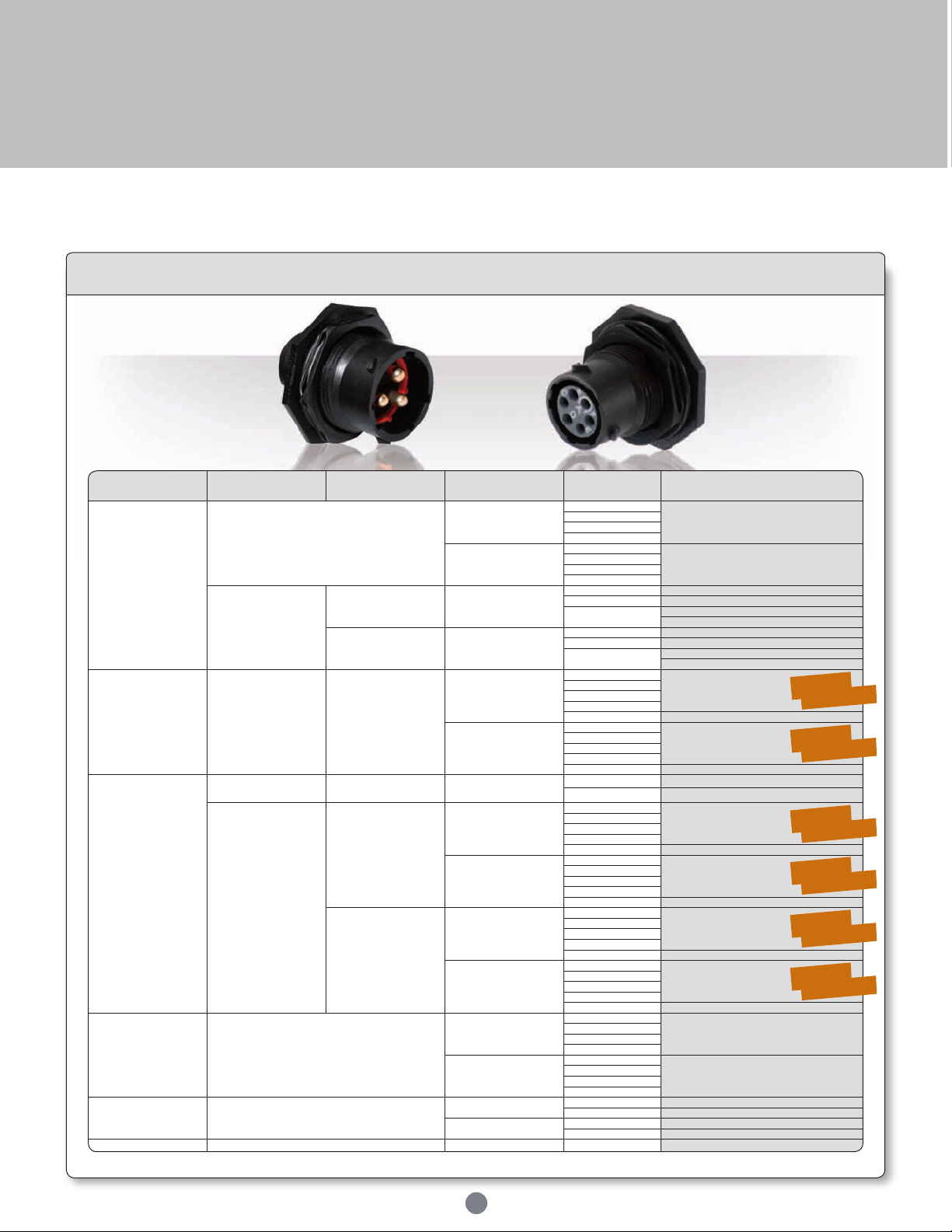
UTS Series
Contact type Connector type Termination Contact sex Shell size Part number
Crimp
contacts supply
separately
UTS standard
Male
10
UTS7 - - P
12
14
18
Female
10
UTS7 - - S
12
14
18
Discrete wire
sealing
Nut and
grommet
Male
10 UTS7GN104P
12 UTS7GN128P
14
UTS7GN147P
UTS7GN1412P
Cable gland
and grommet
Male
10 UTS7GJC104P
12 UTS7GJC128P
14
UTS7GJC147P
UTS7GJC1412P
Solder
contacts loaded
Hi seal
with stand off
Standard
receptacle
Male
8
UTS7 - E - P
10
12
14
18 On demand
Female
8
UTS7 - E - S
10
12
14
18 On demand
PCB
contacts loaded
UTS standard
with stand off
Receptacle
with hold down clip
Male
12 UTS7128PSEK9
14 UTS7147PSEK9
Hi seal
with stand off
Receptacle
without hold
down clip
Male
8
UTS7 - D - P
10
12
14
18 On demand
Female
8
UTS7 - D - S
10
12
14
18 On demand
Receptacle
with hold
down clips
Male
8
UTS7 - D - P32
10
12
14
18 On demand
Female
8
UTS7 - D - S32
10
12
14
18 On demand
PCB
contacts supply
separately
UTS standard
Male
10
UTS7 - - P
12
14
18
Female
10
UTS7 - - S
12
14
18
Screw
contacts loaded
UTS standard
Male
12 UTS7124PSCR
14 UTS7147PSCR
Female
12 UTS7124SSCR
14 UTS7147SSCR
RJ45 UTS standard -
18 UTS718RJFN
Mechanics
UTS jam nut receptacle with accessories
Part number
For coding " - - " see p.6 and UTS layout guide p.12.
28
Sealed
Unmated
Sealed
Unmated
Sealed
Unmated
Sealed
Unmated
Sealed
Unmated
Sealed
Unmated
Page 29
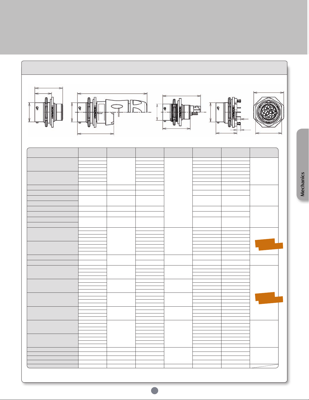
UTS Series
Part number Shell size
L
(total length)
ØA B C D Figure
UTS7 - - P
10
33.9
14.9
19.3
27 22.2
Fig. 1
12 19 31.8 27
14 22.2 34.9 30.2
18 28.5 41.3 36.6
UTS7 - - S
10 14.9 27 22.2
12 19 31.8 27
14 22.2 34.9 30.2
18 28.5 41.3 36.6
UTS7GN104P
10
41
14.9 27 22.2
Fig. 2
UTS7GN128P
12
40.7
19 31.8 27
UTS7GN147P
14
43
22.2 34.9 30.2
UTS7GN1412P
UTS7GJC104P
10
70.5
14.9 27 22.2
Fig. 3
UTS7GJC128P
10
74
19 31.8 27
UTS7GJC147P
14
80.5
22.2 34.9 30.2
UTS7GJC1412P
UTS7 - E - P
8
25
12
19.3
24 19.3
Fig. 5
10 14.9 27 22.2
12 19 31.8 27
14 22.2 34.9 30.2
UTS7 - E - S
8 12 24 19.3
10 14.9 27 22.2
12 19 31.8 27
14 22.2 34.9 30.2
UTS7128PSEK9
12
25
19
19.3
31.8 27
Fig. 6
UTS7147PSEK9
14 22.1 34.9 30.2
UTS7 - D - P
8
25
12
19.3
24 19.3
Fig. 6
10 14.9 28 22.2
12 19 31.8 27
14 22.2 34.9 30.2
UTS7 - D - S
8
25
12
19.3
24 19.3
10 14.9 28 22.2
12 19 31.8 27
14 22.2 34.9 30.2
UTS7 - D - P32
8
25
12
19.3
24 19.3
10 14.9 28 22.2
12 19 31.8 27
14 22.2 34.9 30.2
UTS7 - D - S32
8
25
12
19.3
24 19.3
10 14.9 28 22.2
12 19 31.8 27
14 22.2 34.9 30.2
UTS7 - - P
10
33.9
14.9
19.3
27 22.2
Fig. 5
12 19 31.8 27
14 22.2 34.9 30.2
18 28.5 41.3 36.6
UTS7 - - S
10 14.9 27 22.2
12 19 31.8 27
14 22.2 34.9 30.2
18 28.5 41.3 36.6
UTS7124PSCR
12
46.5
19
19.3
31.8 27
Fig. 4
UTS7147PSCR
14
52.5
22.2 34.9 30.2
UTS7124SSCR
12
38.3
19 31.8 27
UTS7147SSCR
14
44.4
22.2 34.9 30.2
UTS718RJFN
18
48
28.5
19.3
41.3 36.6
Dimensions
L
B
ØA
Fig. 1 Fig. 2
H (for PCB contact): PCB nominal length (see page 30)
For coding " - - " see p.6 and UTS layout guide p.12.
ØA
L
Fig. 3
L
ØA
Fig. 4
L
ØA
L
Fig. 5 Fig. 6
29
H
L
4
Note : all dimensions are in mm
C
D
Front view
Mechanics
Sealed
Unmated
Sealed
Unmated
Page 30
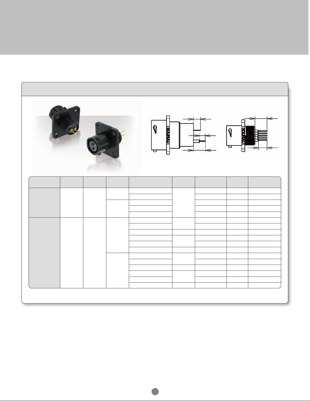
UTS Series
Contact type
Connector
type
Contact
size
Contact
sex
Part number
Shell
size
Layout A C
PCB
contacts
supply
separately
UTS0
Standard
16
Male
RM20M12E8□
10 to 18
- 50.2 -
RM20M12E83□ - 10.3 -
Female
RC20M12E8□ - 5.2 -
RC20M12E83□ - 10.4 -
RC20M12E84□ - 13.9 -
PCB
contacts
loaded
UTS0
Hi seal
16 & 20
Male
8
8E2 8E3 8E4 - 9.76 to 11.86
- 8E3A 8E98 - 10.78 to 13.09
- 10 - - 8.1 to 10.5
-
12
- - 8.1 to 10.5
- 1214 - 7.2 to 9.3
- 14 - - 8.1 to 10.5
Female
8
8E2 8E3 8E4 - 9.55 to 11.71
- 8E3A 8E98 - 10.82 to 12.79
- 10 - - 8.15 to 10.15
-
12
- - 8.15 to 10.15
- 1214 - 7.3 to9.3
- 14 - - 8.15 to 10.15
Mechanics
Solder tail protrusion
Dimensions
A
7
B
C
6.6
□ = plating - see available plating p.44
Note : all dimensions are in mm
30
Page 31
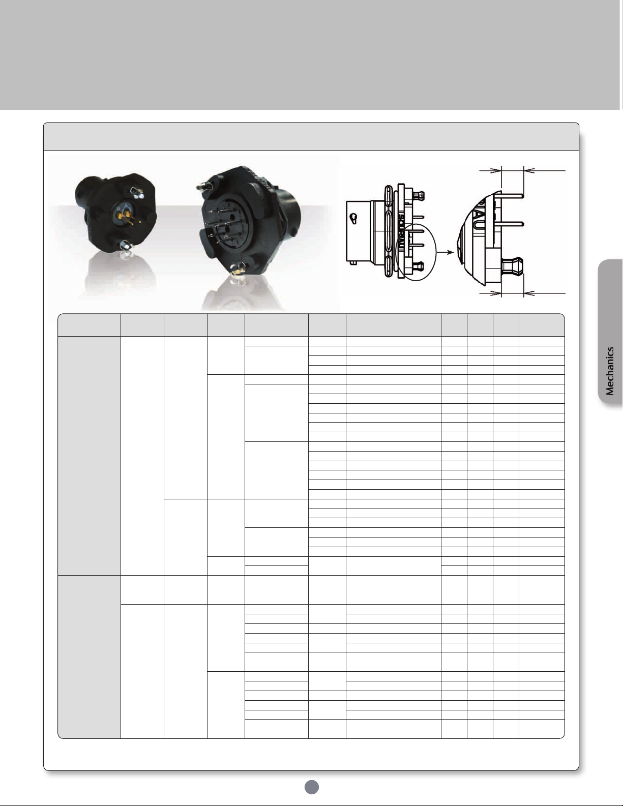
UTS Series
Contact type
Connector
type
Contact
size
Contact
sex
Part number
Shell
size
Layout A B C D
PCB
contacts
supply
separately
UTS7
Standard
16
Male
RM20M12E8□ 10 to 18 - 4.1 - - -
RM20M12E83□
10 to 18 - 9.2 - - -
20 & 22 - 4.85 - - -
24 - 3.35 - - -
Female
RC20M12E84□ 10 to 18 - 4.65 - - -
RC20M12E85□
10 & 12 - 7.15 - - -
14 - 7.85 - - -
16 & 18 - 7.15 - - -
20 - 3.4 - - 22 - 2.7 - - 24 - 1.3 - - -
RC20M12E86□
10 & 12 - 7.95 - - -
14 - 8.65 - - -
16 & 18 - 7.95 - - -
20 - 4.2 - - 22 - 3.5 - - 24 - 2.1 - - -
20
Male
RMW50A7K
10 to 16 - 9.51 - - 18 to 22 - 5 - - -
24 - 3.6 - - -
RMW5016K
10 to 16 - - 10.41 - 18 to 22 - - 6 - -
24 - - 4.6 - -
Female
RCW50A7K
10 to 16 -
2.4 - - -
RCW5016K 3.04 - -
PCB
contacts loa-
ded
UTS7
with stand
off version
16
Male &
Female
- 12 & 14 - - - 3.6 -
UTS7
Hi seal
without
stand off
20
Male
8
8D2 8D3 8D4 - - - 3.8 to 6
- 8D3A 8D98 8D33 - - - 4.7 to 7.25
- 10 10D6 10D7 - - - 4.9 to 7
-
12
12D2 12D3 12D8 12D10 - - - 4.8 to 7
- 12D14 - - - 3.85 to 5.9
- 14
14D5 14D12 14D15
14D18 14D19
- - - 4.8 to 7
Female
8
8D2 8D3 8D4 - - - 3.75 to 5.8
- 8D3A 8D98 8D33 - - - 4.8 to 6.9
- 10 10D6 10D7 - - - 4.9 to7
-
12
12D2 12D3 12D8 12D10 - - - 5.2 to 7
- 12D14 - - - 3.85 to 5.9
- 14
14D5 14D12 14D15
14D18 14D19
- - - 5.3 to 7
Dimensions
D
4
□ = plating - see available plating p.44
Note : all dimensions are in mm
31
Mechanics
Page 32
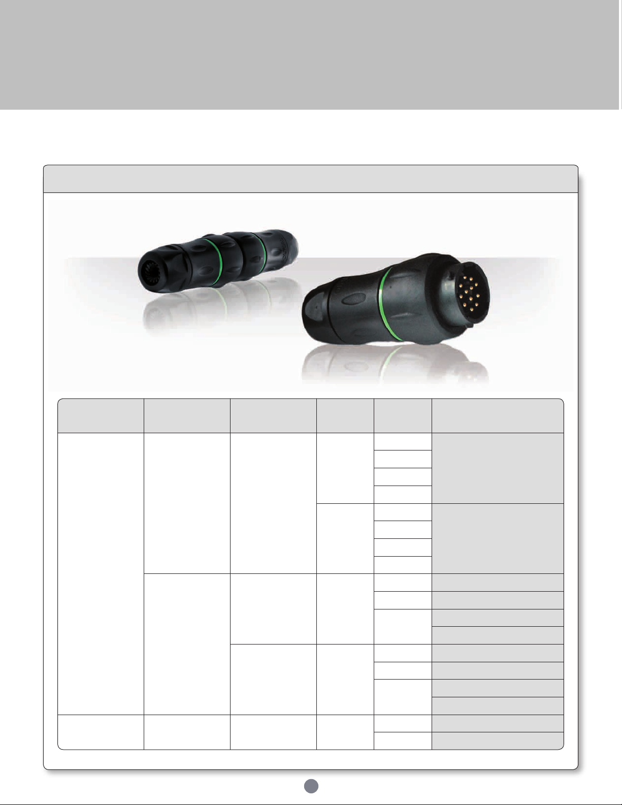
UTS Series
Contact type Connector type Termination Contact sex
Shell
size
Part number
Crimp
contacts
supply
separately
UTS standard Cable gland
Male
10
UTS1JC - - P
12
14
18
Female
10
UTS1JC - - S
12
14
18
Discrete wire
sealing
Nut and
grommet
Male
10 UTS1GN104P
12 UTS1GN128P
14
UTS1GN147P
UTS1GN1412P
Cable gland
and grommet
Male
10 UTS1GJC104P
12 UTS1GJC128P
14
UTS1GJC147P
UTS1GJC412P
Screw
contacts loaded
UTS standard
Cable gland
backshell
Male
12 UTS1JC124PSCR
14 UTS1JC147PSCR
Mechanics
UTS in line receptacle with accessories
Part number
For coding " - - " see p.6 and UTS layout guide p.12.
32
Page 33
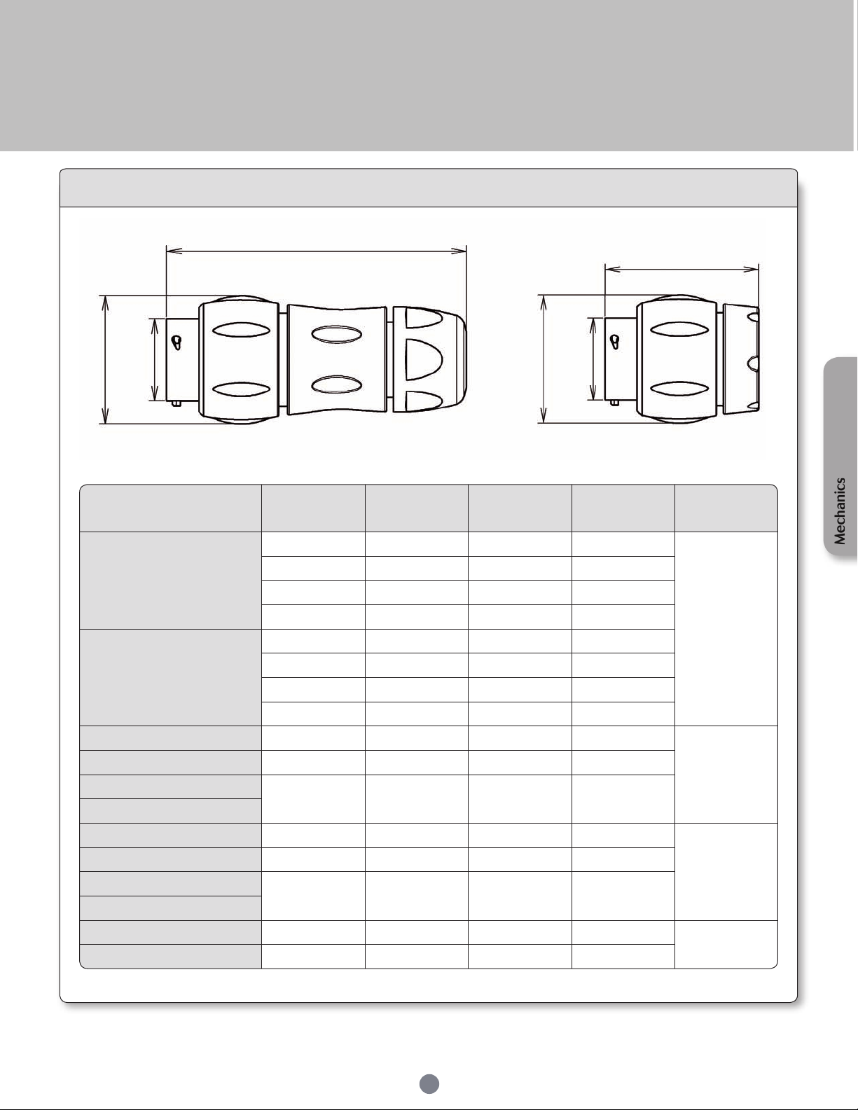
UTS Series
Part number
Shell
size
L
(total length)
ØA B Figure
UTS1JC - - P
10 70 14.9 26.7
Fig. 1
12 74 19 30.1
14 78.5 22.2 35.1
18 89 28.5 42
UTS1JC - - S
10 70 14.9 26.7
12 74 19 30.1
14 78.5 22.2 35.1
18 89 28.5 42
UTS1GN104P 10 40.9 14.9 26.2
Fig. 2
UTS1GN128P 12 40.9 19 29.7
UTS1GN147P
14 43 22.2 34.6
UTS1GN1412P
UTS1GJC104P 10 70.7 14.9 26.2
Fig. 1
UTS1GJC128P 12 74.5 19 29.7
UTS1GJC147P
14 80.5 22.2 34.6
UTS1GJC412P
UTS1JC124PSCR 12 74 19 29.7
Fig. 1
UTS1JC147PSCR 14 78.5 22.2 34.6
Dimensions
L
L
ØB
ØA
Fig. 1 Fig. 2
ØB
ØA
Mechanics
For coding " - - " see p.6 and UTS layout guide p.12.
33
Note : all dimensions are in mm
Page 34
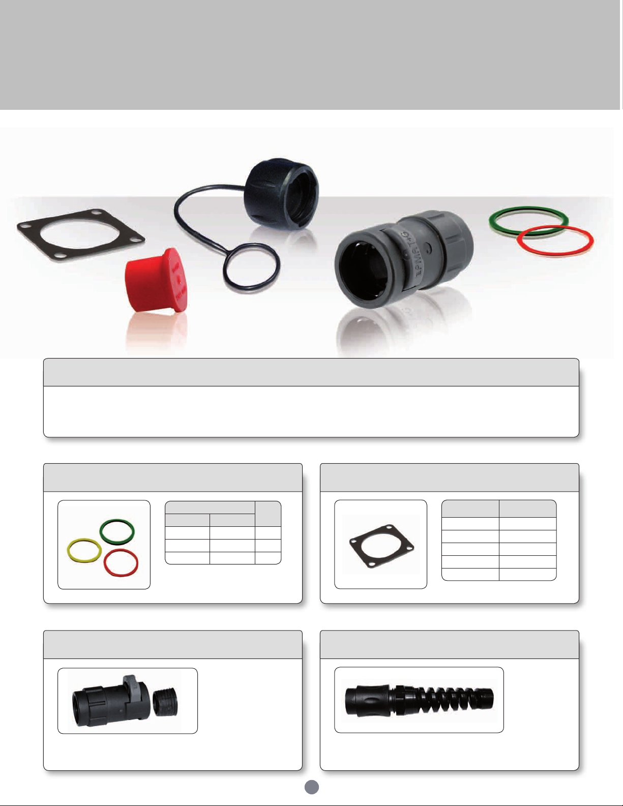
UTS Series
Part numbers
Shell
size
Receptacles Plugs
UTS710CCR* UTS610CCR* 10
UTS712CCR* UTS612CCR* 12
UTS714CCR* UTS614CCR* 14
Part numbers /
neoprene
Shell size
UTFD11B 8
UTFD12B 10
UTFD13B 12
UTFD14B 14
UTFD16B 18
Accessories
Description
UTS series offers a wide range of accessories: from the plastic protective cap to the dust caps, coloured rings for visual identification or
discrimination pins.
Colour coding rings
* Add G for Green, Y for Yellow, R for Red
For shell sizes 8 & 18, please consult factory
PMA adapter
IP40 version
Bending protection spiral
Gasket
IP68/69K
version
To get a PMA adapter you should change JC to PMA.
Ex: UTS6JC - - S UTS6PMA - - S
To get a spiral protection you should change JC to JS.
Ex: UTS6JC - - S UTS6JS - - S
34
Page 35
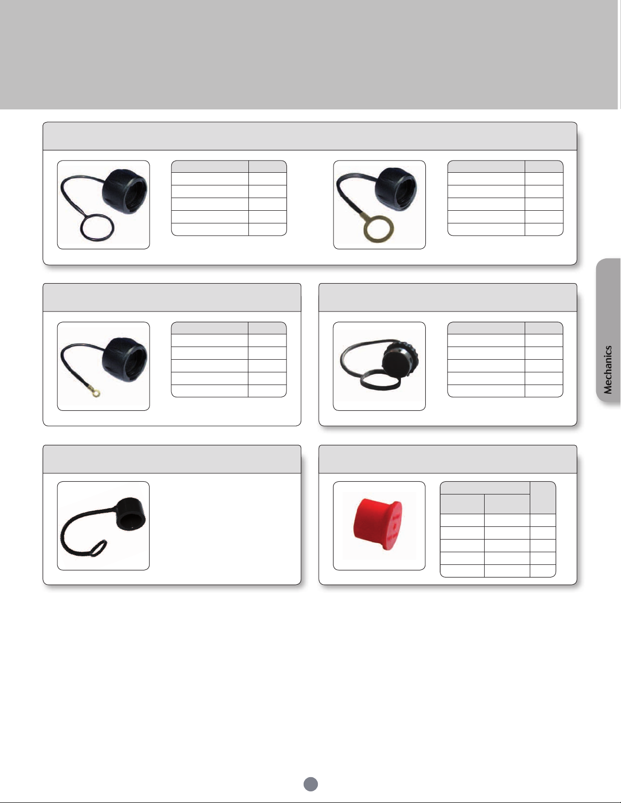
UTS Series
Part numbers Shell size
UTS8DCG 8
UTS10DCG 10
UTS12DC G 12
UTS14DC G 14
UTS18DCG 18
Part numbers Shell size
UTS8DCGE 8
UTS10DCGE 10
UTS12DC GE 12
UTS14DC GE 14
UTS18DCGE 18
Part numbers Shell size
UTS68C ** 8
UTS610DCG 10
UTS612DCG 12
UTS614DCG 14
UTS618DCG 18
Part numbers Shell size
UTS8DCGR 8
UTS10DCGR 10
UTS12DC GR 12
UTS14DC GR 14
UTS18DCGR 18
Part numbers
Shell
size
Receptacle
cap
Plug cap
8500-5585A 8500-5594 8
8500-5586A 8500-5595 10
8500-5587A 8500-5596 12
8500-5588A 8500-5597 14
8500-5590A 8500-5599 18
Metal terminal
Square flange sealing cap
Jam nut sealing caps
Metal terminal
* Except for UTS RJ45 plug / ** Non sealed
Plug sealing cap*
Mechanics
Plug protective cap
Size 8
IP40
Part number: UTS68C
35
Plastic protective cap
Page 36
UTS Series
Connector
type
Backshell
type
Gender
Connector
size
Part number
1m of cable 3m of cable 5m of cable
UTS
standard
Straight
Male
10 to 18
HAUTSOV - - PSTR100 HAUTSOV - - PSTR300 HAUTSOV - - PSTR500
Female HAUTSOV - - SSTR100 HAUTSOV - - SSTR300 HAUTSOV - - SSTR500
90°
Male HAUTSOV - - PRA100 HAUTSOV - - PRA300 HAUTSOV - - PRA500
Female HAUTSOV - - SRA100 HAUTSOV - - SRA300 HAUTSOV - - SRA500
UTS Hi seal
Straight
Male
8 to 14
HAUTSOV - E - PSTR100 HAUTSOV - E - PSTR300 HAUTSOV - E - PSTR500
Female HAUTSOV - E - SSTR100 HAUTSOV - E - SSTR300 HAUTSOV - E - SSTR500
90°
Male HAUTSOV - E - PRA100 HAUTSOV - E - PRA300 HAUTSOV - E - PRA500
Female HAUTSOV - E - SRA100 HAUTSOV - E - SRA30 HAUTSOV - E - SRA500
Connector
type
Backshell
type
Gender
Connector
size
Part number
1m of cable 3m of cable 5m of cable
UTS
standard
Straight
Male
10 to 18
HAUTS - - PSTR100 HAUTS - - PSTR300 HAUTS - - PSTR500
Female HAUTS - - SSTR100 HAUTS - - SSTR300 HAUTS - - SSTR500
UTS Hi seal Straight
Male
8 to 14
HAUTS - E - PSTR100 HAUTS - E - PSTR300 HAUTS - E - PSTR500
Female HAUTS - E - SSTR100 HAUTS - E - SSTR300 HAUTS - E - SSTR500
Cable assembly
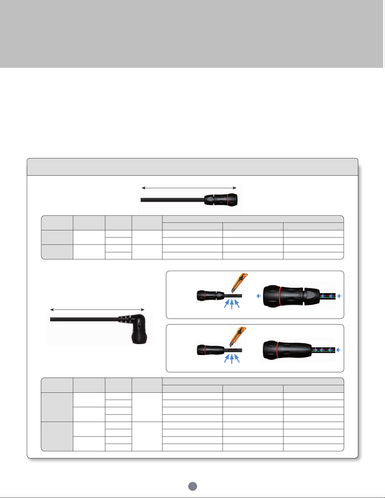
Souriau provides connectors in various applications for more than 90 years in the most extreme environment.
Being conscious about the difculty to nd a quick and a reliable harness manufacturer, we decided years ago to start in house cable
assembly production. It allows customers to reduce the number of suppliers, and to take advantage of the "best in class" quality of the
Souriau group. Overmoulding is a process that further enhances the sealing properties of the UTS range, especially over many years
of use. Overmoulding provides the opportunity to change the cable exit from straight through 90 degrees and avoid any stress on the cable
terminated to the connector. Also, as the wires are encapsulated inside the moulding, a barrier is created which prevents from any liquid from entering
the equipment through the connector if the cable jacket is breached.
In this section you’ll nd standard cable sets but as all customers are unique we are happy to adapt our proposal to your specic needs on demand.
Harnesses
Standard harnesses
Overmoulded harnesses
Total length
Free end
Total length
Free end
Discrete
connector
If cable jacket is breached... water ingress unhampered, leading to damage.
Overmoulded
connector
Other lengths and configurations: on demand, see factory
Note: UTS standard necessarily with gold plated stamped & formed contacts
If cable jacket is breached... prevents water ingress via capillary action.
36
Page 37
UTS Series
Connector type
Number and size of
wires
Cable used
Shell size
Arrangement
for UTS standard
Type Harmonised reference
8
8E2 2 #20 2X0.5 H05 V V - F 2X0.5
8E3; 8E3A; 8E33 3 #20 3X0.5 H05 VV - F 3X0.5
8E4 4 #20 4X0.5 H05 V V - F 4X0.5
10
103PE 3 #16 3G1.5 H05 VV - F 3G1.5
103 3 #16 3X1.5 H05 VV - F 3X1.5
104 4 #16 4X1.5 H05 VV - F 4X1.5
106; 1098 6 #20 7X0.5 H05 VV - F 7X0.5
10E7 7 #20 7X0.5 H05 VV - F 7X0.5
12
12E2 2 #16 2X1.5 H05 VV - F 2X1.5
12E3 3 #16 3X1.5 H05 VV - F 3X1.5
124PE 4 #16 4G1.5 H05 VV - F 4G1.5
128 8 #16 8X1.5 H05 VV - F 8X1.5
12E8 8 #20 10G0.5 H05 VV - F 10G0.5
1210 10 #20 10G0.5 H05 VV - F 10G0.5
1214 14 #20 14G0.5 H05 VV - F 14G0.5
14
14E2 3 #8 3G10 H05 VV - F 3G10
147PE 7 #16 7G1.5 H05 VV - F 7G1.5
1412 12 #16 12X1.5 H05 VV - F 12X1.5
14E12 8 #20; 4 #16 12G0.5 H05 VV - F 12G0.5
14E15 14 #20; 1 #16 18G0.5 H05 VV - F 18G0.5
14E18 18 #20 18G0.5 H05 VV - F 18G0.5
1419 19 #20 21G0.5 H05 VV - F 21G0.5
18
18E11 11 #16 12X1.5 H05 VV - F 12X1.5
1823 23 #16 25G1 H05 VV - F 25G1.5
18E30 29 #20; 1 #16 30G0.5 H05 VV - F 30G0.5
1832 32 #20 35G0.5 H05 VV - F 35G0.5
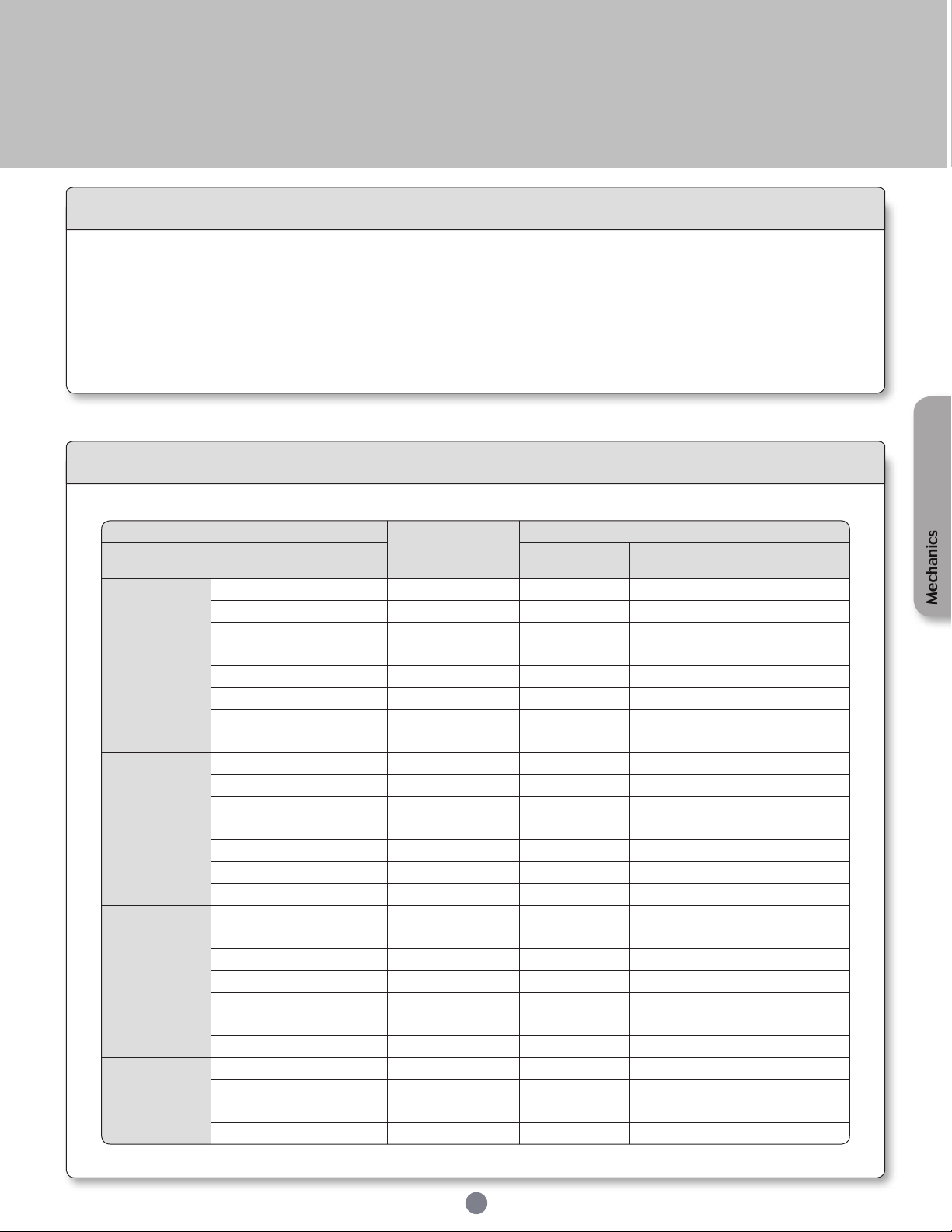
Cable information
Range of temperature: Occasional exing: -5°C up to +70°C
Fixed installation: -40°C up to +80°C
Rated voltage: U0/U: 300/500 V
Wire section : Arrangement with #16 contact: wire section 1.5 mm²
Arrangement with #20 contact: wire section 0.5 mm²
Cable selection
37
Mechanics
Page 38

Page 39
UTS Series
Contacts
Description ........................................................................................................................................
Contact plating selector guide ....................................................................................................
Contact selector guide ..................................................................................................................
Packaging ..........................................................................................................................................
Crimp contacts .................................................................................................................................
Coaxial contacts ..............................................................................................................................
PCB contacts ....................................................................................................................................
Fibre optic contacts ........................................................................................................................
40
41
42
42
43
45
46
47
Page 40
UTS Series
Contacts
Description
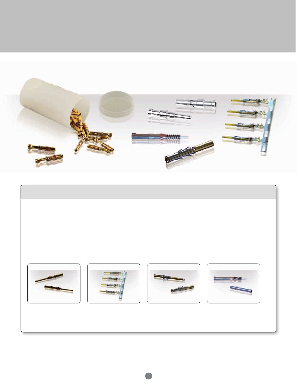
The UTS series offers the unique possibility to use the same contact in any layout as long as it receives the same active part size. Thus it is
possible to buy only one contact reference and equip all connectors even if housings are different.
The main benefit is the standardisation which means reduction of inventory cost.
Bearing in mind that any additional tool or complicated assembly process should be avoided, our contacts are based on a snap-in principle
which avoid the use of an insertion tool.
Crimp contacts are available in different versions:
• machined • stamped & formed • coaxial • fiber optic
In addition, UTS series can obviously be equipped with solder contacts, PCB contacts, screw termination and RJ45.
40
Page 41
UTS Series
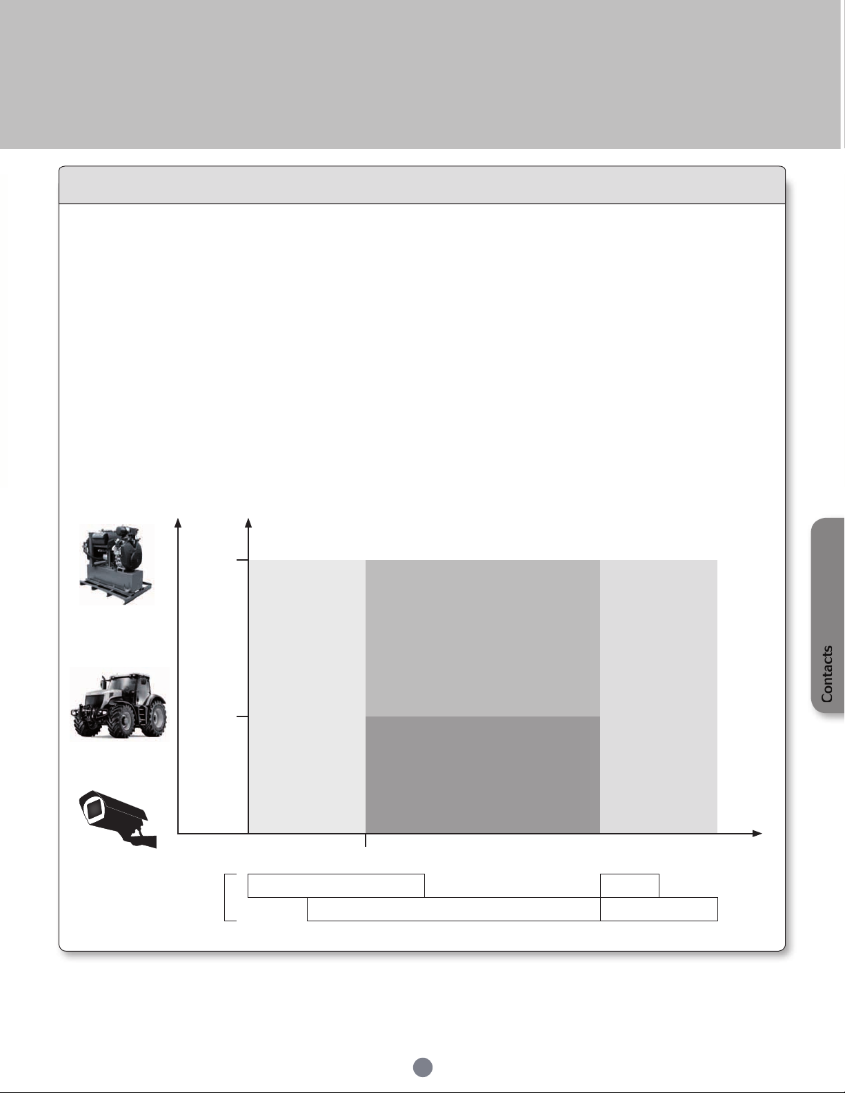
Contact plating selector guide
As soon as you know what contact size you need, you next have to decide on which type to use.
Souriau proposes mainly two different types of electrical contacts:
- Machined
- Stamped & formed
Machined contacts are generally chosen for low quantities purpose as well as a better solution for power
applications.
Stamped & formed contacts offer the ability to be crimped automatically which makes them more suitable for
high volume production applications.
Then comes the question: What plating should I choose ?
Hereunder is a graph with criteria to guide you:
Vibration
Contact
size
Number of
cycles
250
100
0.4μm of gold
min
#20 #12
5mA
5mV
Gold flash
Silver
Tin
#16 #8
Contacts
Current /
Voltage
41
Page 42
UTS Series
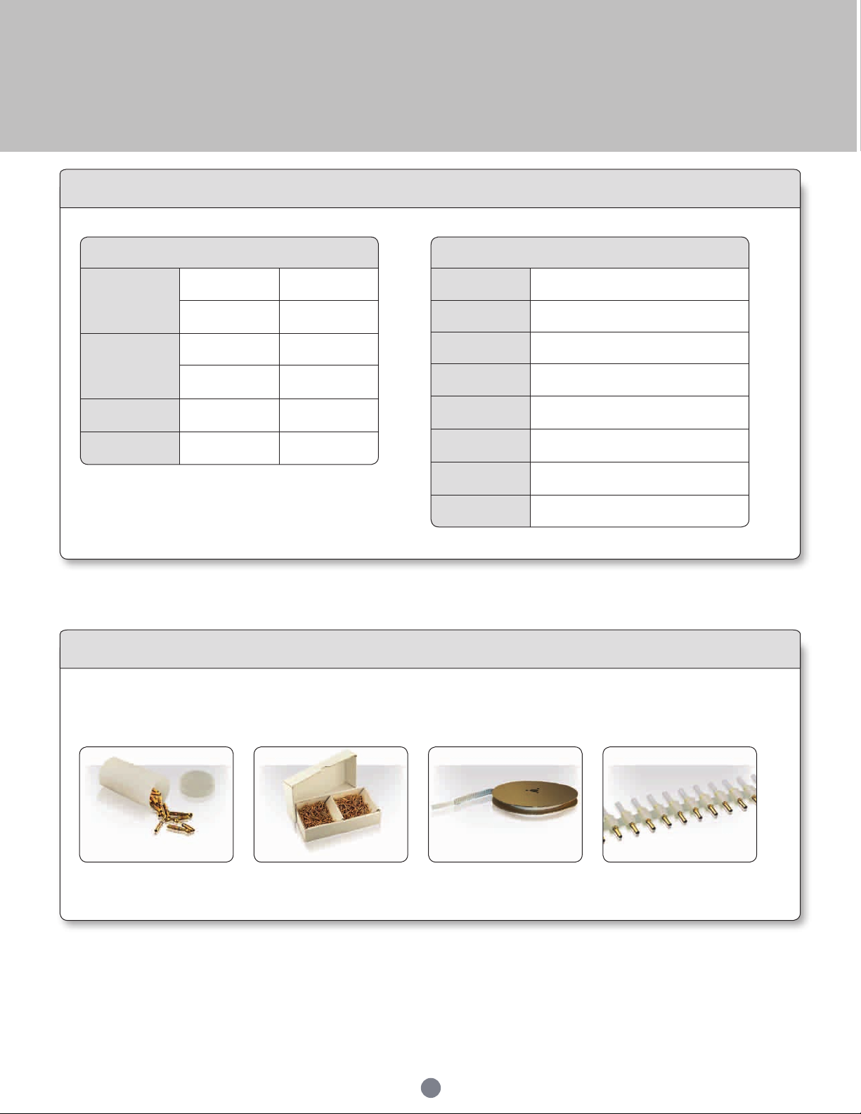
Electrical characteristics: contact resistance
#20
Ø1mm
Machined < 6mΩ
Stamped &
formed
< 15mΩ
#16
Ø1.6mm
Machined < 3mΩ
Stamped &
formed
< 6mΩ
#12
Ø2.4mm
Machined < 5mΩ
#8
Ø3.6mm
Machined < 5mΩ
Available platings
A 2μ Ni + 2μ Ag
J Gold ash over 2μ Ni
K Min 0.4μ gold over 2μ Ni
S31 Gold ash over Ni
S18
0.75μ gold min in active part over 2μ Ni
Gold ash over Ni
S25
S26
Active part: 0.75μ Au over Ni
Crimp area: ash Au over Ni
T
T: 2μm Ni mini all over + 3 to 5 μm Sn
all over
TK6 2-5μ Sn pre-plated
Contact selector guide
Conscious of the wide variety of applications, contact packaging has been considered for small series (bulk packaging) and high volume
production (reeled contacts):
• 50 pieces bulk packing
(standard)
Packaging
• 1000 pieces bulk packing • 5000 pieces reeled machined
• 3000 pieces reeled stamped
& formed contacts
42
contacts
Page 43
UTS Series
Contact
size
Type
Wire size Part number
Max
wire Ø
Max
insulator
Ø
Color band
Plating
available
AWG mm² Male Female Front Rear
#20
Ø1 mm
Machined 26-24 0.13-0.20 RM24W3- RC24W3- 1.58 max - - K
S&F 26-24 0.13-0.25
SM24W3S26 (1) SC24W3S25 (1)
0.89-1.58
- -
S25, S26
SM24WL3S26 (2) SC24WL3S25 (2) - -
Machined 22-20 0.32-0.52 RM20W3- RC20W3- 1.58 max - - K
S&F 22-20 0.35-0.5
SM20W3S26 (1) SC20W3S25 (1)
1.17-2.08
- -
S25, S26
SM20WL3S26 (2) SC20WL3S25 (2) - -
Machined 20-18 0.50-0.93 RM18W3- RC18W3- 2.10 max - - K
#16
Ø1.6
mm
Machined 30-28 0.05-0.08 RM28M1- RC28M1- 0.55 1.1 - - K, J, T
Machined 26-24 0.13-0.2 RM24M9- RC24M9- 0.8 1.6 Red - K, J, T
S&F 26-24 0.13-0.25
SM24M1- (1)
SM24ML1- (2)
SC24M1- (1)
SC24ML1- (2)
0.89-1.28 - - S31, S18, TK6
Machined 22-20 0.32-0.52
RM20M13- RC20M13-
1.18
1.8 Black -
K, J, T
RM20M12- RC20M12- 2.2 Blue -
S&F 22-20 0.35-0.5
SM20M1- (1)
SM20ML1- (2)
SC20M1- (1)
SC20ML1- (2)
1.17-2.08 - - S31, S18, TK6
Machined 20-16 0.52-1.5 RM16M23- RC16M23- 1.8 3.2 - - K, J, T
S&F 18-16 0.8-1.5
SM16M1- (1)
SM16ML1- (2)
SC16M1- (1)
SC16ML1- (2)
3.0 - - S31, S18, TK6
S&F 18-16 0.8-1.5
SM16M11- (1)
SM16ML11- (2)
SC16M11- (1)
SC16ML11- (2)
2.0-3.0 - - S31, S18, TK6
Machined 16-14 1.5-2.5 RM14M50- RC14M50- 2.05 3.2 - - K, J, T
Machined 16-14 1.5-2.5 RM14M30- RC14M30- 2.28 3.2 - - K, J, T
S&F 14 2.0
SM14M1- (1)
SM14ML1- (2)
SC14M1- (1)
SC14ML1- (2)
3.2 - - S31, S18, TK6
#12
Ø2.4 mmMachined
22 0.13-0.4 8291 1457N- 8291 1456-
- 4.9 - A, K
20 0.5 8291 1459N- 8291 1458-
18 0.75-1.0 8291 1461N- 8291 1460-
16 1.5 8291 1463N- 8291 1462-
14 2.5 8291 1465N- 8291 1464-
12 4 8291 1467N- 8291 1466-
#8
Ø3.6 mmMachined
16 1.5 8291 3601- 8291 3600-
- 6.5 - A
14 2.5 8291 3603- 8291 360212 4 8291 3605- 8291 3604-
10 6.0 8291 3607- 8291 3606-
8 10.0 8291 3609- 8291 3608-
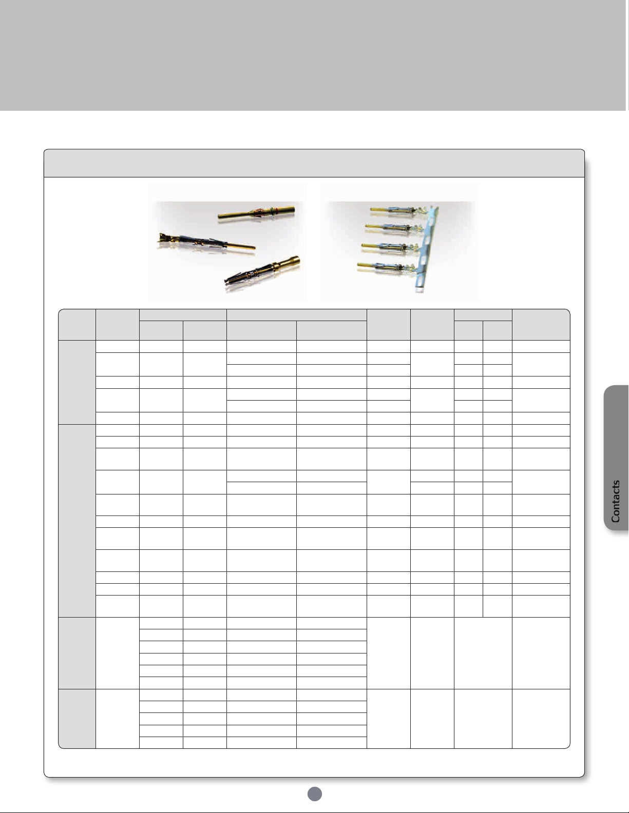
Crimp contacts
Standard version
(1) contact reeled
(2) loose contact
43
Contacts
Page 44
UTS Series
Contact
size
Type
Wire size Part number
Max
wire Ø
Max
insulator Ø
Color band
Plating
available
AWG mm² Male Female Front Rear
#16
Ø1.6 mm
Longer male
contact
(+1mm)
Machined
30-28 0.05-0.08 RM28M1GE1□
-
0.55 1.1 - Red
□ =
K, J or T
26-24 0.13-0.2 RM24M9GE1□ 0.8 1.6 Red Red
22-20 0.32-0.52
RM20M13GE1□
1.18
1.8 Black Red
RM20M12 GE1□ 2.2 Blue Red
20-16 0.52-1.5 RM16M23 GE1□ 1.8 3.2 - Red
16-14 1.5-2.5 RM14M50 GE1□ 2.05 - - Red
16-14 1.5-2.5 RM14M30 GE1□ 2.28 - - Red
#16
Ø1.6 mm
Shorter fe-
male contact
(-0.7mm)
Machined
30-28 0.05-0.08
-
RC28M1GE7□ 0.55 1.1 - Blue
□ =
K, J or T
26-24 0.13-0.2 RC24M9GE7□ 0.8 1.6 Red Blue
22-20 0.32-0.52
RC20M13GE7□
1.18
1.8 Black Blue
RC20M12GE7□ 2.2 Blue Blue
20-16 0.52-1.5 RC16M23GE7□ 1.8 3.2 - Blue
16-14 1.5-2.5 RC14M50GE7□ 2.05 - - Blue
16-14 1.5-2.5 RC14M30GE7□ 2.28 - - Blue
Contact 1
Contact 2
Standard male
contact
Standard female
contact
Longer male
contact
Standard male
contact
Standard female
contact
FMLB
Shorter female
contact
LMFB
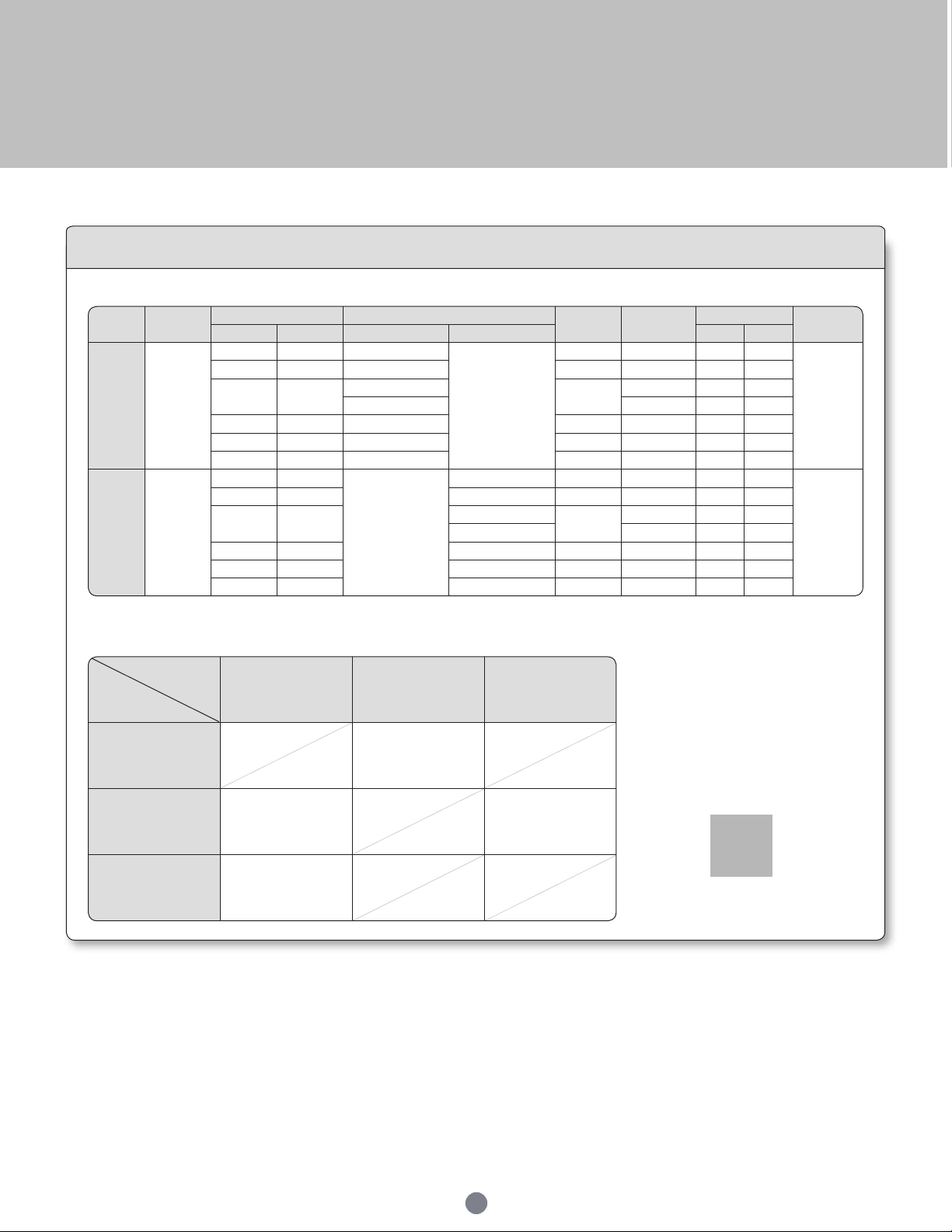
Crimp contacts
First Mate Last Break contacts
How to make FMLB / LMFB connection
44
First Mate Last Break contacts should
be chosen only if the cavity is not
marked with the earth symbol. For
cavities marked with the earth symbol,
standard contacts will fulll the same
role as a rst mate, last break contact
used in a standard cavity.
Ground symbol
Page 45
UTS Series
Contact type
Contact range Contact part
number with cable
combination
Cabling notice
Male contact Female contact
Multipiece RM DXK10D28 RCDXK1D28
See page 68
See pages 72 & 73
Monocrimp RMDX60xxD28 RCDX60xxD28 See page 74
Contact type
Contact range Contact part
number with cable
combination
Cabling notice
Male contact Female contact
Multipiece
RMDXK10D28
+ YORK090
RCDXK1D28
+ YORK090
See page 69
See page 70
Monocrimp RMDX60xxD28 RCDX60xxD28 See page 71
Coaxial contacts
Coaxial contact range
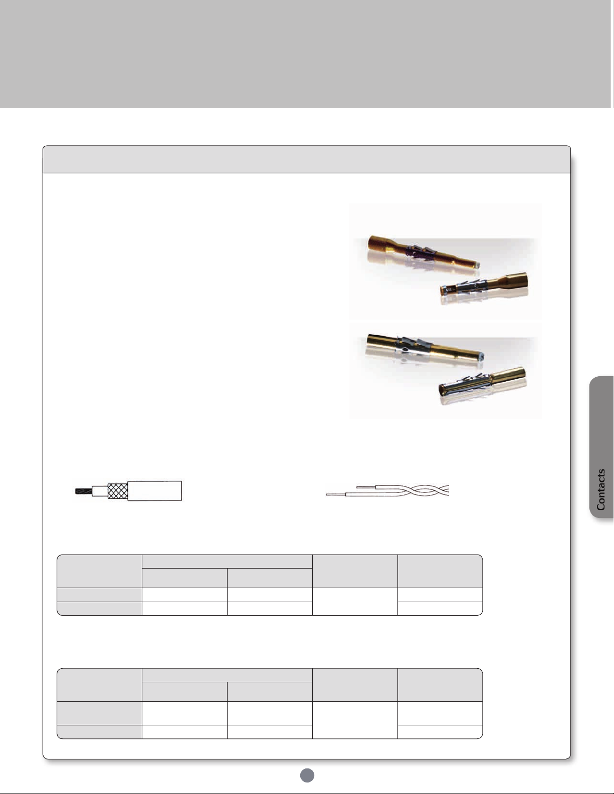
We provide 2 types of coaxial contacts suitable for 50 or 75Ω, coaxial cable or twisted pair cable.
Monocrimp coaxial contact
• The monocrimp one-piece coaxial contacts offer high reliability plus
the economic advantage of a 95% reduction in installation time over
conventional assembly methods.
• This economy is achieved by simultaneously crimping both the inner
conductor and outer braid or drain wire.
Multipiece crimp coaxial contact
• The inner conductor and outer braid is crimped individually.
• The thermoplastic insulating bushing in the outer body is designed
to accept and permanently retain the inner contact.
• An outer ferrule is used to connect the braid to the outer contact
and provide cable support to ensure against bending and vibration.
Suitable for Coaxial cable or Twisted cable
• For jacket diameter from 1.78 to 3.05mm
Inner conductor up to 2.44mm diameter
Contacts for coaxial cable summary
Contacts for twisted pairs cable summary
• For jacket diameter from 0.64 to 1.45mm
Inner conductor from AWG30 to AWG24
Contacts
45
Page 46
UTS Series
Contact size Type
Part number
Plating
Male Female
#20
Ø1mm
Short version RMW50A7□ RCW50A7□
□ = K
Long version RMW5016□ RCW5016□
#16
Ø1.6mm
Short version RM20M12E8□ RC20M12E8□
□ = K or T
Long version RM20M12E83□
RC20M12E83□
RC20M12E84□
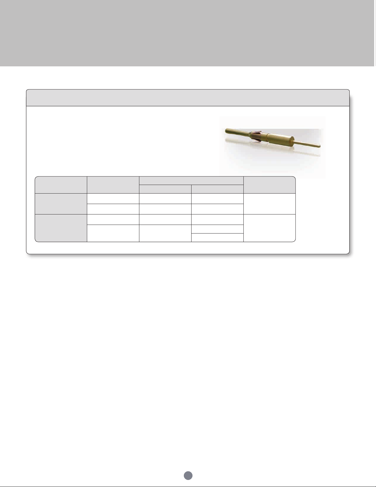
PCB contacts
PCB contacts
PCB soldering
UTS range can be carried out with a wave soldering process, but not reow
soldering process. All high temperature processes are prohibited.
46
Page 47
UTS Series
Fibre optic contacts
Description
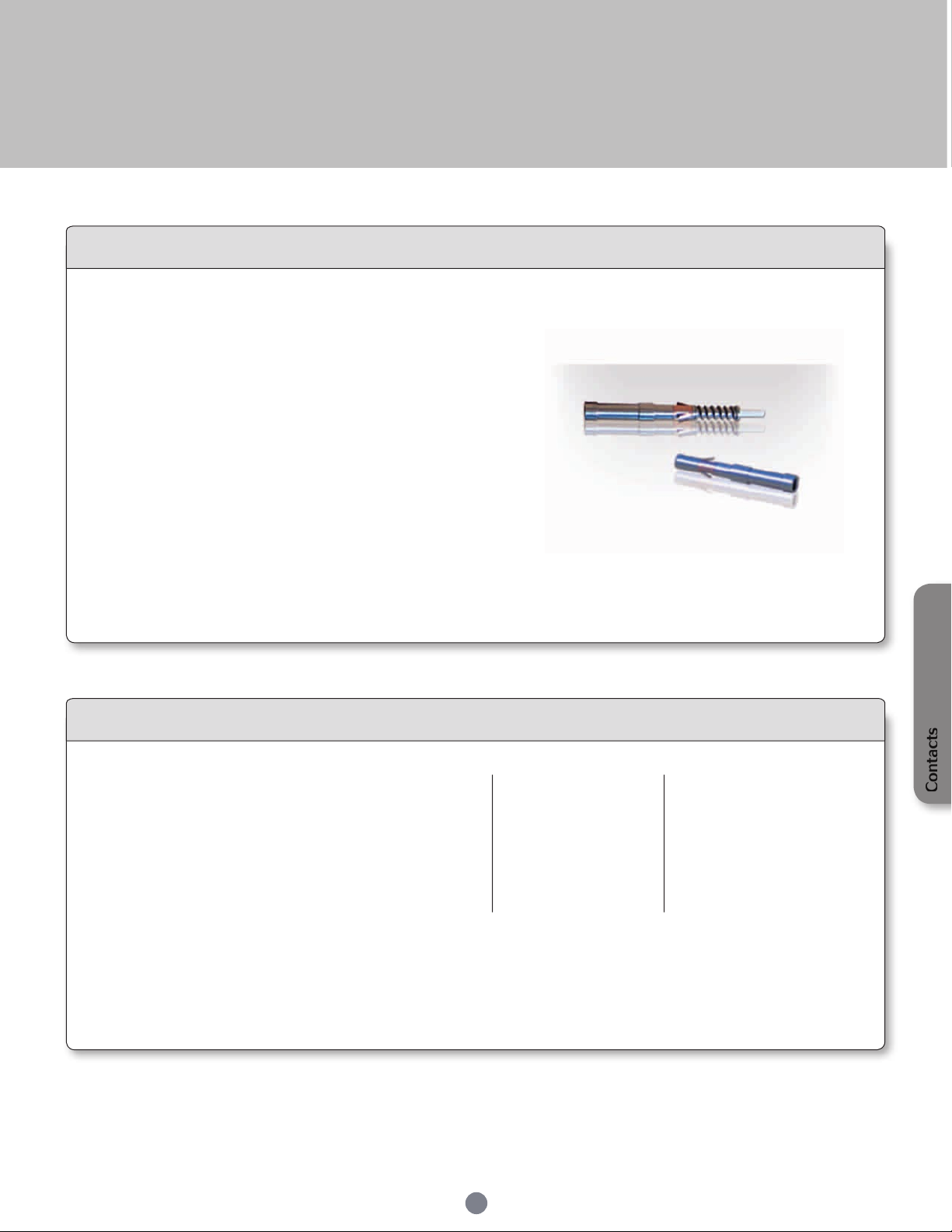
Size 16 Fibre optic contacts for TRIM TRIO® connectors
Size 16 Fibre optic contacts are optical contacts designed for the integration of optical links in all TRIM TRIO® cable connectors.
The Fibre optic contacts are designed to accommodate:
• Plastic Optical Fibre (POF)
1 mm core and 2.2 mm jacket
• Plastic Clad Fibre (PCF)
230µm core and 2.2 mm jacket
• Multimode Silica Fibre
62.5/125µm type 2.0 mm max. jacket
• Singlemode Silica Fibre
9/125µm type 2.0 mm jacket
Typical features and benefits are:
• Socket contact is spring loaded to avoid any air gap between the two optical faces.
• Low insertion loss is provided by high precision pieces.
• Single jumpers, multiway harness and active device housings can be supplied regarding customer requirement.
Technical characteristics
Performance
• Fibre type: POF/PCF Multimode Singlemode
62.5/125μm 9/125μm
• Wave length: 650 nm 1300 nm 1310 nm
• Optical insertion loss (typ.): 2 dB max. < 0.5 dB < 0.35 dB
• Jacketed external diameter: 2.2mm 2.0mm max. 2.0mm max.
• Temperature range: -25°C to +70°C -25°C to +70°C -25°C to +70°C
• Cable retention: 49N
• Mating cycles without cleaning: 50
• Max. mating cycles: 500
Construction
• Contact body: Copper alloy
Connector accommodation
Any TRIM TRIO® size 16 contact can be used in any contact position in any connector in the TRIM TRIO® size 16 interconnection
system : UTP, UTS, UTG, UTO.
Contacts
47
Page 48
UTS Series
Part numbers Descriptions
80WD0005
Stripping tool
80WD0025
Automatic stripping tool for Ø 0.5 mm, 0.6
mm, 0.7 mm & 3.8 mm
80WM0006
Ruler
80WP0005
Polishing plate
80WP0013
Non slip base (to hold the polishing plate)
80WP0014
Polishing disk (grain size 9µm)
80WP0018
Polishing tool
80WP0019
Polishing disk (grain size 30µm)
80WS0002
Crimping plier
Part numbers Descriptions
80WG0010
Needle
80WG0015
Capsule
80WG0016
Syringe
80WN0005
Dry air spray
80WN0006
Optical paper
80WN0012
Dropping bottle
80WN0008
Wiping solvent
Descriptions
Stripping tool for Ø 2.2 mm
Kevlar scissors
Stripping tool for Ø 0.25 mm
Alumina blade
Polishing tool
Press t tool
Microscope
Descriptions
Polishing disk (grain size 9µm)
Polishing disk (grain size 0.3µm)
Curing oven
Polishing plate
Non slip base (to hold the polishing plate)
Glue
Fibre optic contacts
Ordering information
POF Contacts (Plastic Optical Fibre)
Male contact RMPOF1000
Female contact RCPOF1000B
PCF Contacts (Plastic Clad Fibre)
Male contact RMPCF230
Female contact RCPCF230B
POF Contact (Plastic Optical Fibre)
STANDARD TOOLING KIT - P/N 80MS0004
The
standard tooling kit
that can be ordered separately as well.
is made of the part numbers below
Silica Contacts - Multimode
Male contact RMMMOFA
Female contact RCMMOFA
Silica Contacts - Monomode
Male contact RMSMOFA
Female contact RCSMOFA
SPECIFIC TOOLING LIST - can be ordered only separately
STANDARD TOOLING KIT - P/N 80MG0039
PCF Contact (Plastic Clad Fibre)
48
Page 49
UTS Series
Part numbers Descriptions
80WC0001 Aramid yarn scissors
80WC0003 Cutter
80WC0004 Alumina blade
80WD0008 Stripping tool for Ø 0.20 mm
80WD0010 Stripping tool for Ø 0.25 mm
80WD0014 Stripping tool for Ø 0.60 mm
80WD0025
Automatic stripping tool for Ø 0.5 mm,
0.6 mm, 0.7 mm & 3.8 mm
80WM0006 Ruler
80WP0005 Polishing plate
80WP0013
Non slip base (to hold the polishing
plate)
80WT0008 Curing oven
80WT0009 Protective tube
Part numbers Descriptions
80WD0036 Stripping tool for Ø 0.9 mm & 0.25 mm
80WD0005 Stripping tool for Ø 2.2 mm & 1.5 mm
80WL0001 Microscope x400
80WL0008 Microscope adaptor
80WP0025 Polishing tool
80WS0002 Crimping tool
80WT0005 Contact support for polymerisation
80WG0010 Needle
80WG0014 Glue
80WG0015 Capsule
80WG0016 Syringe
80WN0005 Dry air spray
80WN0006 Optical paper
80WN0012 Dropping bottle
80WP0014 Polishing disk (grain size 9µm)
80WP0015 Polishing disk (grain size 0.3μm)
Fibre optic contacts
Multimode Contact - Silica
STANDARD TOOLING KIT - P/N 80MG0027
The
standard tooling kit
that can be ordered separately as well.
is made of the part numbers below
SPECIFIC TOOLING LIST - can be ordered only separately
Contacts
49
Page 50

Page 51
UTS Series
Technical information
Tooling ................................................................................................................................................
Assembly instruction ......................................................................................................................
Rated current & working voltage ................................................................................................
UV resistance ...................................................................................................................................
Crimping .............................................................................................................................................
UL94 + UL1977 ..............................................................................................................................
IEC 61984 and IP codes explained ..........................................................................................
What is NEMA rating ? ..................................................................................................................
52
54
58
59
59
60
63
65
Page 52
UTS Series
Tooling
Automatic crimping tools
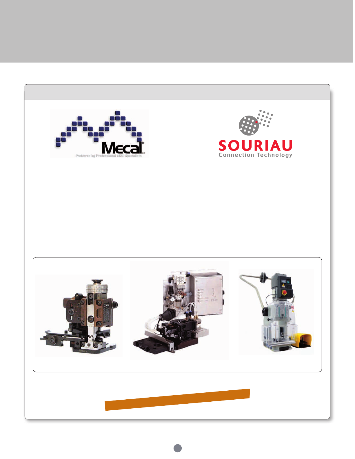
Mecal is leader in manufacturing tooling for
crimping terminals over a stripped wire.
Established in 1976, Mecal has become one of the
world's leading companies dedicated to the design
and manufacture of semi automatic production tools
for strip fed, open barrel crimp terminals, serving
the Automotive, Telecom and Datacomm industry.
Souriau has been working in partnership with Mecal for a good number of years. With sales offices located
in all major industrial regions of the world, the combined strengths of both organisations has resulted in a
truly global solution to all your production tooling needs.
The extreme environment interconnect specialist
“from deep sea to deep space”.
Souriau designs manufactures and markets high
performance interconnect solutions for severe
environments dedicated to the aerospace, defence,
light and heavy industry markets.
Mini Applicator Stripper Presses
Mecal sales network:
www.mecal.net/eng/retevendita.php
52
Page 53
UTS Series
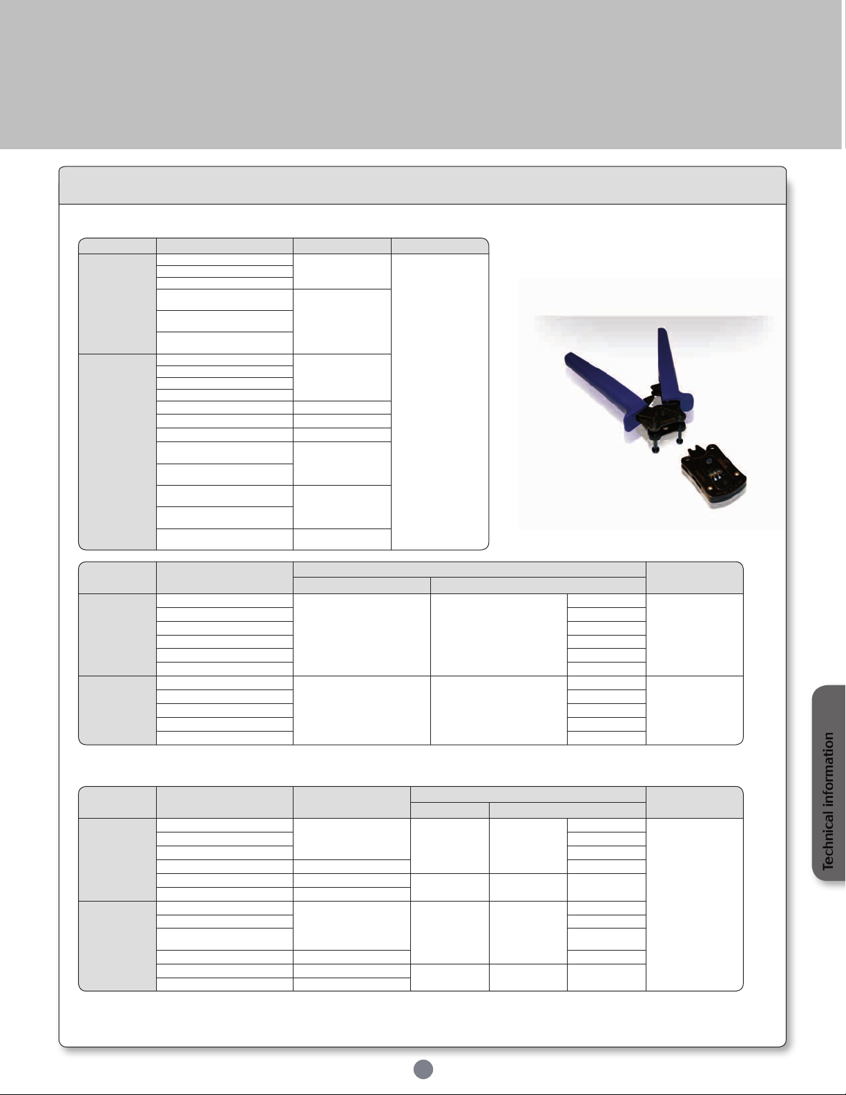
Contact size Part number Head Handles
#20
1mm
RM/RC 24W3 -
S20RM
SHANDLES
RM/RC 20W3 RM/RC 18W3 SM 24W3S - (1)
SC 24W3S - (1)
S20SCM20
SM 24WL3S - (2)
SC 24WL3S - (2)
SM/SC 20W3S - (1)
SM/SC 20WL3S - (2)
#16
1.6mm
RM/RC 28M1 -
S16RCM20
RM/RC 24M9 RM/RC 20M13 RM/RC 20M12 -
RM/RC 16M23 -
S16RCM16
RM/RC 14M50 -
S16RCM1450
RM/RC 14M30 -
S16RCM14
SM/SC 24M1 SM/SC 24ML1 -
S16SCM20
SM/SC 20M1 SM/SC 20ML1 -
SM/SC 16M1 SM/SC 16ML1 -
S16SCML1
SM/SC 14M1 -
SM/SC 14M L1 SM/SC 16M11 -
SM/SC 16ML11 -
S16SCML11
Contact size Part number
Tool with separate locator
Extraction tools
Hand tool Positioner + locator setting
12
2.4mm
8291 1457N- / 8291 1456-
M317 VGE10077A
1-2
5106 02 09 24
8291 1459N- / 8291 1458-
2
8291 1461N- / 8291 1460-
2
8291 1463N- / 8291 1462-
3
8291 1465N- / 8291 1464-
3
8291 1467N- / 8291 1466-
4
#8
3.6mm
8291 3601A / 8291 3600A
M317 VGE10078A
3
5106 021 09 36
8291 3603A / 8291 3602A
3
8291 3605A / 8291 3604A
4
8291 3607A / 8291 3606A
5
8291 3609A / 8291 3608A
6/7
Contact size Part number
Hand tools
(SHANDLES) head
Tool with separate locator
Extraction tools
Hand tool Positioner + locator setting
#16
Ø 1.6mm
Longer RM
contact
RM28M1GE1-
S16RCM20
MH860 MH861686
4/6
RX2025GE1
RM24M9GE1-
5/6
RM20M13GE1-
6/7
RM16M23 GE1-
S16RCM16 6/8
RM14M50 GE1-
S16RCM1450
M317 UH2-5 3
RM14M30 GE1-
S16RCM14
#16
Ø 1.6mm
Shorter RC
contact
RC28M1GE7-
S16RCM20
MH860 MH861646
4/6
RC24M9GE7-
5/6
RC20M13G E7RC20M12G E7-
5/7
RC16M23GE7-
S16RCM16 6/8
RC14M50G E7-
S16RCM1450
M317 UH2-5 3
RC14M30G E7-
S16RCM14
Standard contacts
Crimptooling table
Specific contacts
Coaxial contacts
See cabling notice pages 68 to 74.
53
Technical information
Page 54
UTS Series
Shell size
Jam nut
torque (Nm)
Ø Wire
Standard
version
Discrete
wire
sealing
8 1.5
3.2 mm
max.
from
1.7 mm
to
3.0 mm
10 3
12 4
14 5
18 5
Part number
Stripping length
L (mm)
Male Female
Machined contact #16
RM28M1-
RM24M9RM20M13RM20M12-
RC28M1-
RC24M9RC20M13RC20M12-
4.8
RM16M23-
RM14M50RM14M30-
RC16M23-
RC14M50RC14M30-
7.1
Stamped & formed contact #16
SM24M1-
SM24ML1-
SM20M1-
SM20ML1-
SC24M1-
SC24ML1-
SC20M1-
SC20ML1-
4
SM16M1-
SM16ML1-
SC16M1-
SC16ML1-
6.35
SM16M11-
SM16ML11-
SC16M11-
SC16ML11-
4.65
SM14M1-
SM14ML1-
SC16M11-
SC16ML11-
6.35
Machined contacts #20
RM24W3RM20W3RM18W3-
RC24W3-
RC20W3-
RC18W3-
4.8
Stamped & formed contact #20
SM24W3-
SM24WL3-
SM20W3-
SM20WL3-
SC24W3-
SC24WL3-
SC20W3-
SC20WL3-
4
Part number
Stripping length
L (mm)
Male Female
Screw contacts
Contact delivered with connector 5.8
Power contacts #12
8291 1457 8291 1459 -
8291 14618291 1463 8291 1465 8291 1467 -
8291 1456 8291 1458 8291 1460 8291 1462 8291 1464 8291 1466 -
7 to 8
Power contacts #8
8291 3601 8291 3603 8291 3605 8291 3607 8291 3609 -
8291 3600 8291 3602 8291 3604 8291 3606 8291 3608 -
6.5 to 7.5
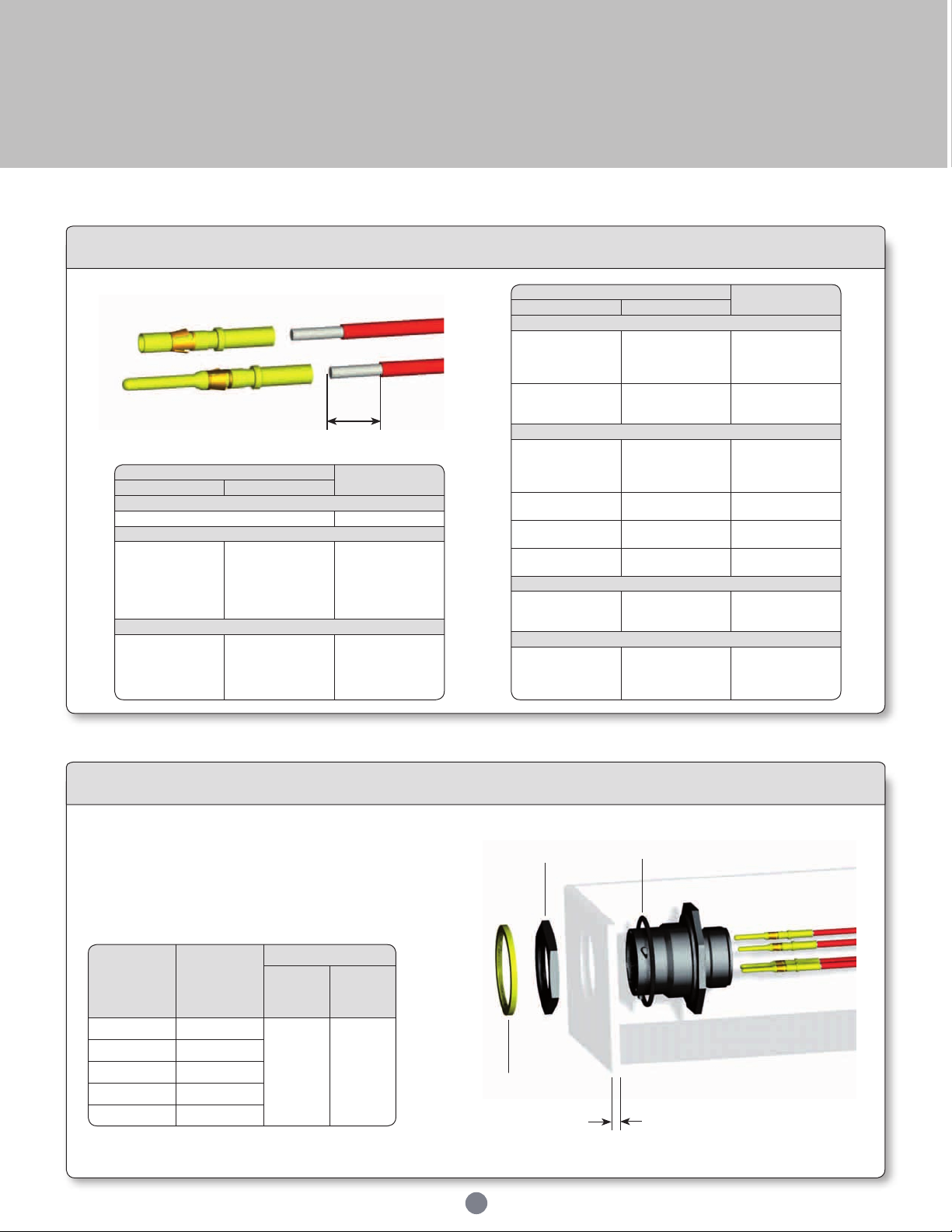
Assembly instruction
Wire stripping
L
• Strip wires, crimp contacts
• Insert contacts into connector cavities (insert
manually or use tool RTM205)
• Seat o-ring, place receptacle in the panel cut-out
• Tighten jam nut
UTS 7 assembly (mounting suggestion)
Jam nut
Optional
coding ring
54
O-ring
Panel thickness:
3.2mm max
Page 55
UTS Series
Shell size
Nut tightening
torque (Nm)
Ø Wire
10 1
from
1.7 mm to
3.0 mm
12 1.5
14 1.5
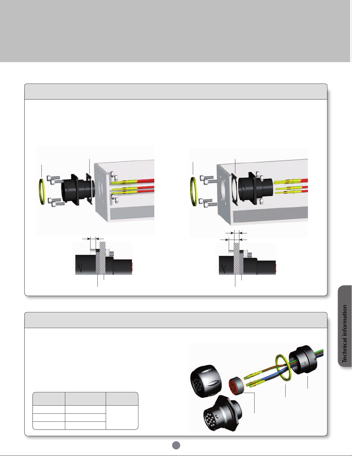
UTS 0 assembly (mounting suggestion)
• Strip wires, crimp contacts
• Insert contacts into connector cavities (insert manually or use tool RTM205)
• Place receptacle in the panel cut-out, with optional gasket
• Secure receptacle with screws (not supplied)
Front mounting
Optional
coding ring
3mm max
Gasket (optional)
Panel
Receptacle flange
Rear mounting
Optional
coding ring
3mm max
Gasket (optional)
Panel thickness: 2.5mm max
Receptacle flange
Panel
• Slide accessories on the cable (make sure to keep compression ring on the grommet)
• Strip wires and crimp contacts
• Insert rst contact into the grommet (rst contact in cavity A, use male contact to
pierce the grommet, no tool is required), then insert the contact in the connector
cavity A (insert manually or use tool RTM205)
• Place the grommet and compression ring on the insulator
• Insert the other contacts
• Tighten nut (recommended torque: see note)
UTS 6 GN / UTS 7 GN assembly
Technical information
Nut
Optional
coding ring
Grommet
+ Compression ring
55
Page 56
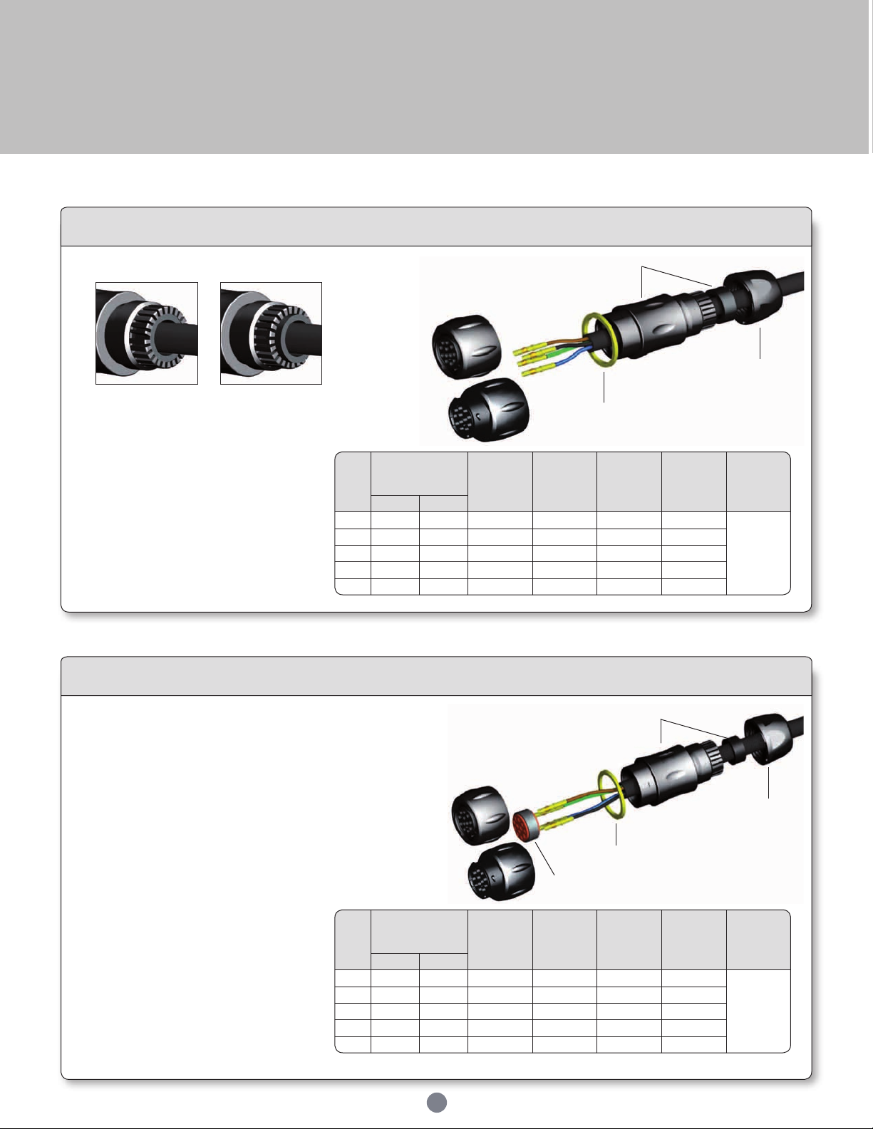
UTS Series
Shell
size
Recommended
jacket strip
length (mm)
Adapter
tightening
torque
(Nm)
Nut
tightening
torque
(Nm)
Ø Cable
range
Standard
seal
Ø Cable
range
Reducing
seal
Ø Wire
Male Female
8 (17) (25) 1 0.75 2.5/6.5 1.5/5.0
3.2 mm
max.
10 21 29 1.5 2 2.5/8.0 1.5/5.0
12 25 33 2 2.5 5.0/12.0 3.0/9.0
14 29 36 3 2.5 7.0/14.0 5.0/12.0
18 37 45 4 3.5 9.0/18.0 7.0/16.0
Shell
size
Recommended
jacket strip
length (mm)
Adapter
tightening
torque
(Nm)
Nut
tightening
torque
(Nm)
Ø Cable
range
Standard
seal
Ø Cable
range
Reducing
seal
Ø Wire
Male Female
8 (17) (25) 1 0.75 2.5/6.5 1.5/5.0
from
1.7 mm
to
3.0 mm
10 21 29 1.5 2 2.5/8.0 1.5/5.0
12 25 33 2 2.5 5.0/12.0 3.0/9.0
14 29 36 3 2.5 7.0/14.0 5.0/12.0
18 37 45 4 3.5 9.0/18.0 7.0/16.0
Assembly instruction
UTS 1 JC / UTS 6 JC assembly
• Slide accessories on the cable
Make sure the rubber gasket is positioned as shown.
• Strip external cable jacket
• Strip wires and crimp contacts
• Insert contacts into connector
cavities (insert manually or use tool
RTM205)
• Tighten adaptor with plug, tighten
nut with adaptor (recommended
torque values to be applied
according to the table - right)
Adapter + mounted gasket
Nut
Coding ring
UTS 1 GJC / UTS 6 GJC assembly
• Slide accessories on the cable (make sure to keep
compression ring on the grommet)
• Strip external cable jacket
• Strip wires and crimp contacts
• Insert rst contact into the grommet (rst contact
in cavity A, the contact pierces the grommet, no
tool is required), then insert the contact in the
connector cavity A (insert manually or use tool
RTM205)
• Place the grommet and compression
ring on the insulator
• Insert the other contacts
• Tight adapter with plug, tight nut
with adaptater (recommended
torque values to be applied
according to the table - right)
56
Adapter + mounted gasket
Nut
Optional coding ring
Grommet + Compression ring
Page 57
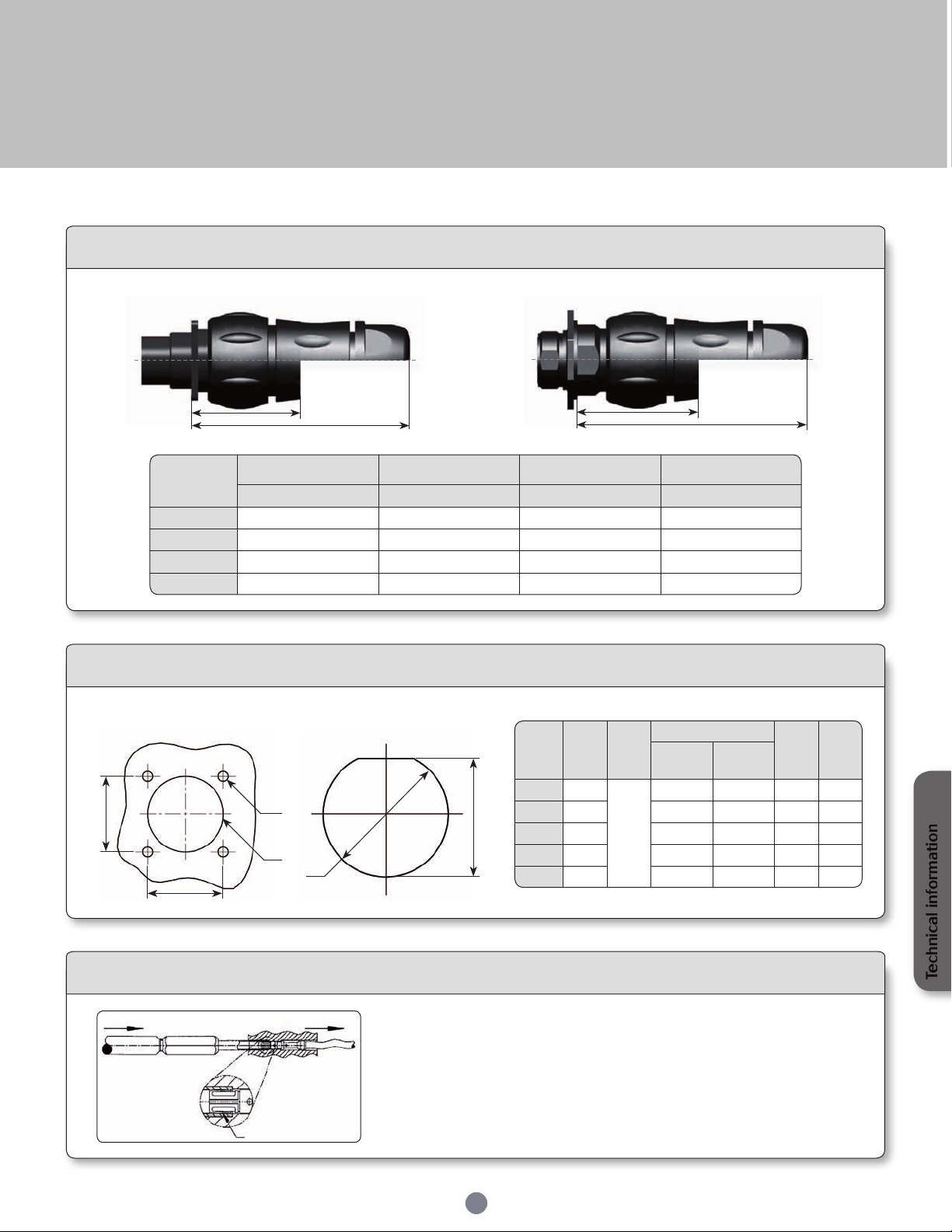
UTS Series
Shell size
UTS0
+ UTS6 EN JC & CJC
UTS0
+ UTS6 EN GN
UTS7
+ UTS6 EN JC & CJC
UTS7
+ UTS6 EN GN
A max B max C max D max
10 73.2 39.6 77.3 43.7
12 77.6 39.4 81.7 43.5
14 83.5 40 87.6 44.1
18 93.1 - 97.2 -
Shell
size
A
±0.25
Ø B
±0.1
Ø C
±0.1
Ø D
±0.2E±0.2
Front
mounting
Rear
mounting
8 15.1
3.2
12.5 14.5 14.6 13.75
10 18.3 15.1 17.8 17.7 16.5
12 20.6 18.2 22.2 22.5 21.2
14 23.0 21.4 25.5 25.7 24.3
18 27.0 27.8 31.8 32 30.6
UTS0 + UTS6
B
A
Mated connector length
UTS7 + UTS6
D
C
Panel cut out
Square flange receptacle
UTS0
A
A
Push
Note : all dimensions are in mm
B
C
D
Contact extraction for size 16 & size 20 contacts
Pull
Locking spring
UTS7
Jam nut receptacle
How to remove a contact out of its cavity?
First of all, if the connector is tted with a backshell, unscrew it and slide it up the cable.
Slide the extraction tip over contact from mating side and push it all the way into the
connector cavity until it stops, indicating that the locking spring from the contact is
depressed.
Push on handle to activate the sprung loaded inner plunger to extract the contact from
the rear of the connector.
E
57
Technical information
Page 58
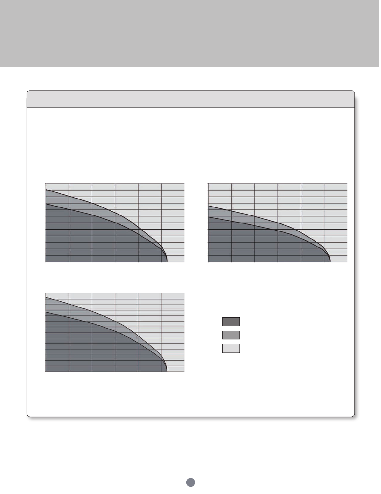
UTS Series
Rated current & working voltage
Current carrying capacity
The current carrying capacity of a connector is limited by the thermal properties of materials used in it's construction. The amount of current
that can be handled depends on the size of cable used, the ambient temperature and the heat that is generated inside the connector. Part 3
of the IEC 60512 standard determines through a derating curve, the maximum current permissible, which varies from one layout to another
(Fig.1 & Fig.2). Wire size plays an important role as well, since they help to dissipate heat and avoid overheating (Fig.1 & Fig.3).
Please note that the curve should be adjusted when dealing with potential hot spots, which can occur as a result of unequal loading of current
across a number of contacts. As a general rule, it is best to avoid locating power handling contacts in the middle of the connector; try to locate
them towards the edge where heat can be dissipated more effectively. Eventually you should nd a level which represents the permissible
operating range:
30
28
25
23
20
18
15
13
Current (A)
10
8
5
3
0
0 20 40 60 80 100 120
Fig.1: UTS 12-4 – 1.5mm² wires
Ambient Operating Temperature (°C)
35
33
30
28
25
23
20
18
15
13
Current (A)
10
8
5
3
0
0 20 40 60 80 100 120
Fig.3: UTS 12-4 – 2.5mm² wires
Ambient Operating Temperature (°C)
30
28
25
23
20
18
15
13
Current (A)
10
8
5
3
0
0 20 40 60 80 100 120
Fig.2: UTS 12-8 – 1.5mm² wires
Ambient Operating Temperature (°C)
Current use
Limited use
Not recommended use
The rated current is dened as uninterrupted continuous current that a connector can take when all contacts are energized simultaneously
without exceeding the maximum limit of temperature. The earth contact is never loaded.
58
Page 59
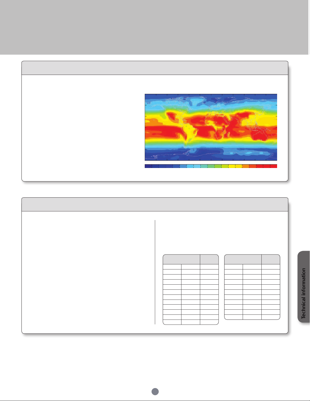
UTS Series
Conductor
cross-section
Pull out
force
MM² AWG N
0.05 30 6
0.08 28 11
0.12 26 15
0.14 18
0.22 24 28
0.25 32
0.32 22 40
0.5 20 60
0.75 85
0.82 18 90
1.0 108
Conductor
cross-section
Pull out
force
MM² AWG N
1.3 16 135
1.5 150
2.1 14 200
2.5 230
3.3 12 275
4.0 310
5.3 10 355
6.0 360
8.4 8 370
10.0 380
UV resistance
Solar radiation affects all materials, but plastics can be
susceptible to extreme degradation over time. The
choice of materials for the UTS series was therefore a
critical consideration.
All over the world we are not exposed to the same
amount of energy given by the sun. The chart shown
here clearly illustrates this.
So we performed test according to the ISO 4892-2 and
simulated 5 years exposure to outdoor environments
(temperature, humidity, etc...)
After this period there was no signicant colour variation,
no crazing, no cracking and no major variation of
mechanical properties.
- 30°
- 60°
- 90°
One of the key factors which affects the performance of
a connector, is the way contacts are terminated. Crimped
connections are nowadays seen as the best solution to ensure
quality throughout the lifetime of the product. Here are some
reasons why we recommend this method of termination for UTS
connectors:
Yearly mean of daily irradiation in UV (280-400 nm)
90°
60°
30°
0°
0
10
20
Crimping
To ensure that the crimp tooling is performing according to
original specications, it is important to carry out regular checks.
A common way to check the performance of tooling is with a
simple pull test, ideally using a dedicated electric pull tester.
Minimum recommended full forces are indicated in the tables
below:
on horizontal plane (J/cm²) (1990-2004)
30
40
70
50
60
80
90
110
120
100
90°60°30°0°- 30°- 90° - 60° 180°150°120°- 180° - 150° - 120°
130
150
140
160
J/cm²
170
180
190
Advantages (Extract from the IEC 60352-2):
- Efcient processing of connections at each production level
- Processing by fully-automatic or semi- automatic crimping
machines, or with hand operated tools
- No cold-soldered joints
- No degradation of the spring characteristic of female contacts
by the soldering temperature
- No health risk from heavy metal and ux steam
- Preservation of conductor exibility behind the crimped
connection
- No burnt, discolored and overheated wire insulation
- Good connections with reproducible electrical and mechanical
performances
- Easy production control
Technical information
59
Page 60
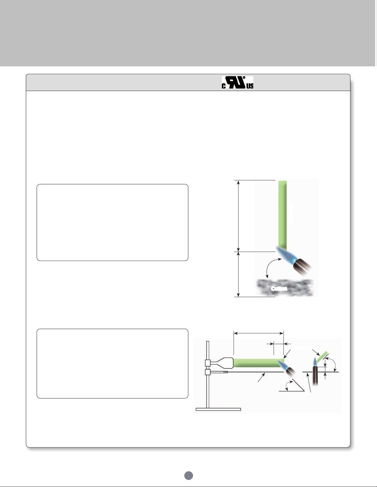
UTS Series
Underwriter Laboratories
There are two main standards for industrial connectors: UL94 & UL1977
UL94
This standard is dedicated to plastics ammability. It characterises how the material burns in various orientation and thicknesses.
The UTS series has been rated at V-0 & HB.
Procedure: A specimen is supported in a vertical or horizontal position and a ame is applied to the bottom of the specimen. The ame is
applied for ten seconds and then removed until aming stops, at which time the ame is reapplied for another ten seconds and then removed.
Two sets of ve specimens are tested. The two sets are conditioned under different conditions.
V-0 :
• Specimens must not burn with aming combustion for more
than 10 seconds after either test ame application.
• Total aming combustion time must not exceed 50 seconds
for each set of 5 specimens.
• Specimens must not burn with aming or glowing combustion
up to the specimen holding clamp.
• Specimens must not drip aming particles that ignite the
cotton.
• No specimen can have glowing combustion remain for longer
than 30 seconds after removal of the test ame.
5’’
Material
45°
HB :
• A material classed HB shall not have a burning rate exceeding
40 mm per minute over a 75 mm span for specimens having
a thickness of 3.0 to 13 mm.
• A material classed HB shall not have a burning rate exceeding
75 mm per minute over a 75 mm span for specimens having
a thickness less than 3.0 mm.
• A material classed HB shall cease to burn before the 100 mm
reference mark.
12’’
~
~
Wire gauze
100±1mm
25±1mm
Cotton
45°
Material
45°
10±1mm
Wire gauze
60
Page 61
UTS Series
Type Flame rating
Relative thermal index (RTI)
Electrical/mechanical w/o impact */**
0 - 50/50
1A HB 50/50
1B HB 50/50
2 HB 50/50
3 HB 50/50
4 HB 50/50
Underwriter Laboratories
UL1977
There are several standards which deal with plug and receptacle. Each of them is only for a small area of applications. It could be
telecommunication, Etc. The UL 1977 covers single and multipole connectors intended for factory assembly.
Requirements apply to devices in taking into account intensity and voltage. There a categories as follows:
0
0
Type 0 Type 1A
8.3 A
31 A
200 A
1000 A
According to above table, the level of performance that has to be reached could be different. Most of them are explained in the following page.
Tybe 1B
30 V
(42 V peak)
Type 4
600 V
Type 2
Type 3
Insulating materials:
Material uses for electrical insulation, as a minimum, have to comply with the characteristics shown below:
• Minimum ratings for polymeric materials
Assembly:
Connector has to be keyed to prevent any mismating that can damage the machine or hurt the user. In the same way, plugs and sockets have
to be equipped to protect persons against contact with live parts.
Finally the identied grounding contact shall be located so that the corresponding electrical continuity has to be completed before any other
contact.
61
* The RTI of the material shall not be lower than the temperature measured during
the Temperature Test.
** For a thickness less than that for which a value has been established, the RTI of
the minimum thickness with an established value shall be used.
Technical information
Page 62
UTS Series
Type
Uninsulated live part - uninsulated
live part of opposite polarity
Uninsulated live part - uninsulated
grounded metal part
Uninsulated live part - exposed
dead metal part
0 No No No
1A Yes Yes Yes
1B Yes Yes No
2 Yes Yes Yes
3 Yes Yes Yes
4 Yes Yes Yes
Underwriter Laboratories
UL1977
Spacing:
For a 250V max connector, distance through air or over material shall be 1.2mm whereas from 250V to 600V connector the spacing is 3.2
minimum. These distances have to be taken between uninsulated live parts as shown in the matrix below:
• Applicability of spacing requirements
An alternative way to determine voltage rating is with the Dielectric-Withstand test. If during one minute there is no arc-over or breakdown
the rated voltage is given as given below:
a) 500 volts for a type 1B device
b) 1000 volts plus twice rated voltage for types 1A, 2, 3 and 4 devices.
Marking:
A device shall be legibly marked with the manufacturer's trade name, trade mark, or other descriptive marking by which the organisation
responsible for the product may be identied. (Exception: If the device is too small, or where the legibility would be difcult to attain, the
manufacturer’s name, trademark, or other descriptive marking may appear on the smallest unit container or carton)
The following shall be marked on the device or on the smallest unit container or carton or on a stuffer sheet in the smallest unit container
or carton:
a) The catalogue number or an equivalent designation
b) The electrical rating in both volts and amperes, if assigned
c) Whether ac or dc, if restricted
d) Flammability class, if identied
Example - Marking for the arrangement 10-3:
10A 500V UL94 V-0
62
Page 63
UTS Series
IEC 61984
The norm is dedicated to connectors with rated voltage above 50V and up to 1000V and rated currents up to 125A per contact. But
depending of your application connectors should be compliant with another standard. This has to be double checked with the customer.
There are lot of constructional requirements and performances specied in that standard. Most of them are illustrated in greater details
hereafter.
Provisions for earthing:
The UTS connector is intended to be used on Class II systems. Even if the purpose of our connector is not to interrupt current, we often
see a need to add a protective earth contact. Then this one shall be a “First mate, last break” style. Critically, among all of the normal
assumptions we make in designing a connector, this contact has to be considered as a live part and must be protected against electric shock
by double or reinforced insulation.
IP Code:
IP is a coding system dened by the IEC 60529 to indicate the
degrees of protection provided by an enclosure. The aim of this is to
give information regarding the accessibility of live parts against ingress
of water and other foreign bodies.
1st digit Degree of protection 2nd digit Degree of protection
0 No protection against accidental contact.
No protection against solid foreign bodies.
1 Protection against contacts with any large area by hand and
against large solid foreign bodies with a diameter bigger than
50 mm.
2 Protection against contacts with the ngers.
Protection against solid foreign bodies with a diameter bigger
than 12 mm.
3 Protection against tools, wires or similar objects with a diame-
ter bigger than 2.5 mm.
Protection against small solid bodies with a diameter bigger
than 2.5 mm.
4 As 3 however diameter is bigger than 1 mm. 4 Splash-proof.
5 Full protection against contacts. Protection against interior
injurious dust deposits.
6 Total protection against contacts. Protection against
penetration of dust.
UTS offers high sealing
performance IP68 / 69K…
Even in dynamic situations.
IEC 61984 ed.2.0 “Copyright © 2008 IEC Geneva, Switzerland.www.iec.ch"
IEC 60664-1 ed.2.0 “Copyright © 2007 IEC Geneva, Switzerland.www.iec.ch”
Code letters
(international
Protection)
0 No protection against water.
1 Drip-proof.
Protection against vertical water drips.
2 Drip-proof.
Protection against water drips up to a 15° angle.
3 Spray-proof.
Protection against diagonal water drips up to a 60° angle.
Protection against splashed water from all directions.
5 Hose-proof.
Protection against water (out of a nozzle) from all directions.
6 Protection against temporary ooding.
7 Protection against temporary immersions.
8 Protection against water pressure.
Pressure to be specied by supplier.
In addition to the IEC 60529 we conjointly use the DIN 40050 part 9
which are dedicated to road vehicles. The main differences are:
• First digit: 5 replaced by 5K, 6 by 6K. In the DIN the tested
equipment is not depressurized as it is in the IEC.
• Second digit: 5K and 6K has been added and are equivalent
respectively to 5 and 6 but with higher pressure.
9K which represents the High pressure cleaning.
9K High pressure hose-proof.
Protection against high pressure water (out of a nozzle) from
all directions.
First digit
(foreign bodies
protection)
IP 6 8
Second digit
(water
protection)
63
Page 64
UTS Series
IEC 61984
Overvoltage
UTS connectors are qualied to be used on systems rated at Overvoltage category III
Per the IEC 60664-1 (formely VDE 0110) each category is linked to the end application and where the device will be implemented:
• Category IV (primary overcurrent protection equipment):
Origin of the installation
• Category III (Any xed installation with a permanent connection)
Fixed installation and equipment and for cases where the reliability and the availability is subject to special requirements
• Category II (Domestic applicances):
Energy consuming equipment to be supplied from the xed installation
• Category I (Protected electronic circuit):
For connection to circuit in which measures are taken to limit transient overvoltage.
Pollution degree
Per the IEC 60664-1 (formerly VDE 0110) the environment affects the performance of the insulation. Particles can build a bridge between
two metal parts. As a rule dust mixed with water can be conductive and more generally speaking metal dust is conductive. Finally, the
standard denes 4 levels of pollution:
• Degree 1 (Air conditioned dry room):
No pollution or only dry, non conductive pollution occurs. The pollution has no inuence.
• Degree 2 (Personal computer in a residential area):
Only non conductive pollution occurs except that occasionally a temporary conductivity caused by condensation is to be
expected.
• Degree 3 (Machine tools):
Conductive pollution occurs or dry non-conductive pollution occurs which becomes conductive due to condensation which is to
be expected.
• Degree 4 (Equipments on roof, locomotives):
Continuous conductivity occurs due to conductive dust, rain or other wet conditions.
Finally, the harsher the environment is, the longer clearance and creepage distances should be. Nonetheless, according the IEC 61984,
enclosure rated at IP54 or higher can be dimensioned for a lower pollution degree. This applies to mated connectors disengaged for test
and maintenance.
Marking
The marking should give enough details to the user to know what the main characteristics are and without going deep in technical
documentation. Below examples identify the suitability of the connector:
• Example 1:
Marking of a connector with rated current 16A, rated voltage 400V, rated impulse voltage 6kV and pollution degree 3, 2 and 1 for
use in any system, preferably unearthed or delta-earthed systems:
16A 400V 6kV 3
16A 400V 6kV 3
• Example 2:
Marking of a connector with rated current 16A, rated insulation voltages line-to-earth 250V, line-to-line 400V, rated impulse
voltage 4kV and pollution degree 3, 2 and 1 for use in earthed systems:
16A 250V 400V 4kV 3
16A 250V 400V 4kV 3
64
Page 65

UTS Series
Enclosure
rating
IP20 IP22 IP55 IP64 IP65 IP66 IP67
Type 1
•
Type 3
•
Type 3R
•
Type 3S
•
Type 4
•
Type 4X
•
Type 6
•
Type 12
•
Type 13
•
What is NEMA rating ?
• NEMA ratings vs IP ratings
Whereas IP ratings only consider protection against ingress of foreign bodies - first digit - and ingress of water
(second digit), NEMA ratings consider these but also verify protection from external ice, corrosive materials, oil
immersion, etc.
The correlation between NEMA & IP being limited only to dust and water, we can state that a NEMA type is
equivalent to an IP rating but it is not possible to say the contrary.
Below a list of some NEMA standards:
• indicates compliance
Type 6 rating can be either Type 6 or Type 6P - please see below:
6 IP67 Enclosures constructed for either indoor or outdoor use to provide a degree of protection
to personnel against incidental contact with the enclosed equipment, falling dirt, hose directed water, the entry of water during occasional temporary submersion at a limited depth
and damage from external ice formation.
6P IP67 Enclosures constructed for either indoor or outdoor use to provide a degree of protection to
personnel against incidental contact with the enclosed equipment, falling dirt, hose-directed
water, the entry of water during prolonged submersion at a limited depth and damage from
external ice formation.
65
Technical information
Page 66

Page 67
UTS Series
Annexes
Coaxial contacts - cabling notices .............................................................................................
Glossary of terms ............................................................................................................................
Coordinates for PC Tail terminations .........................................................................................
Stand off dimensions - Drilling pattern (PCB view).................................................................
Discrimination/Keying methods .................................................................................................
68
75
76
78
79
Page 68
UTS Series
Cable
type
Impe-
dance
Contact
type
Ø over jacket
Ø over
dielectric
Inner
cond
size
Ø outer braid
Male contact kit
for coaxial cable
Female contact
kit for coaxial
cable
inch mm inch mm
Ext. Ø
mm
inch mm
RG161/U 75
Multi
piece
0.09 2.29 0.057 1.45
RMDXK10D28 RCDXK10D28
RG179A/U 75 0.105 2.67 0.063 1.6 0.3 0.084 2.13 max
RG179B/U 75 0.105 2.67 0.063 1.6 0.3 0.084 2.13 max
RG187/U 75 0.11 2.79 max 0.06 1.52 0.3
RG188/U 50 0.11 2.79 max 0.06 1.52 0.51 0.078 1.98 max
RG174/U 50 0.11 2.92 0.06 1.52 0.48 0.088 2.24 max
AMPHENOL 21-598 50 0.105 2.67 0.06 1.52 0.48
RG196/U 50 0.08 2.03 max 0.034 0.086 0.3
RG178A/U 50 0.075 1.91 0.034 0.86 0.3 0.054 1.37 max
RG/188A/U 50
Mono
crimp
0.110 2.79 0.06 1.52 0.51 0.078 1.98 max RMDX60-36D28 RCDX60-36D28
KX21TVT (europe)
RG178 B/U
50 0.075 1.91 0.034 0.86 0.3 0.054 1.37 max RMDX60-34D28 RCDX60-34D28
RG178 / BU 50 0.075 1.91 0.034 0.86 0.3 0.054 1.37 max RMDX60-50D28 RCDX60-16D28
RG174/U 50 0.115 2.92 0.06 1.52 0.48 0.088 2.24 max RM DX60-32D28 RCDX60-32D28
RG188A/U 50 0.11 2.79 0.06 1.52 0.51 0.078 1.98 max RMDX60-36D28 RCDX60-36D28
RG316/U 50 0.107 2.72 0.6 1.52 0.51 0.078 2.05 max RMDX60-36D28 RCDX60-36D28
raychem 5024A3111 50 0.12 3.05 0.083 2.11 0.64 0.097 2.46 RMDX60-52D28 RCDX60-52D28
raychem 5026e1614 50 0.083 2.11 0.05 1.27 0.48 0.067 1.7 RMDX60-36D28 RCDX60-36D28
surprenant pn 8134 -
Multi
piece
0.1 2.54 0.058 1.47 0.3 RMDXK10D28 RCDXK10D28
PRD PN 247AS-
C1123-001
-
Mono
crimp
0.103 2.62 0.06 1.52 0.51 0.078 1.98 RMDX60-18D28 RCDX60-18D28
PRD PN 247AS-C1251 - 0.092 2.34 0.05 1.27 0.64 0.067 1.7 RMDX60-18D28 RCDX60-18D28
JUDD C15013010902 - 0.087 2.13 0.05 1.27 0.48 0.066 1.67 RMDX60-36D28 RCDX60-36D28
CDC PIN22939200 - 0.09 2.29 0.048 1.22 0.3 0.064 1.63 RMDX60-46D28 RCDX60-16D28
CDC PIN22939200 - 0.09 2.29 0.048 1.22 0.3 0.064 1.63 RMDX60-50D28 RCDX60-16D28
CDC PIN245670000 - 0.104 2.64 0.067 1.7 0.3 0.083 2.11 RMDX60-50D28 RCDX60-16D28
ampex - 0.114 2.9 0.075 1.91 0.38 0.09 1.29 RMDX60-32D28 RCDX60-32D28
TI PN 920580 - 0.7 1.78 0.038 0.96 0.48 0.054 1.37 RMDX60-24D28 RCDX60-24D28
Honeywell PN
58000062
- 0.12 3.05 0.077 1.96
0.41
solid
0.096 2.44 RMDX60-26D28 RCDX60-26D28
- - 0.104 2.64 0.067 1.7 0.3 2.11 RMDX60-50D28 RCDX60-50D28
- - 0.09 2.29 0.048 1.22 0.3 1.63 RMDX60-50D28 RCDX60-50D28
- - 0.114 2.9 0.075 1.91 0.38 1.29 RMDX60-32D28 RCDX60-32D28
- - 0.07 1.78 0.038 0.96 0.48 1.37 RMDX60-24D28 RCDX60-24D28
- - 0.12 3.05 0.077 1.96 0.41 2.44 RMDX60-26D28 RCDX60-26D28
Coaxial contacts
Coaxial cable - Contact monocrimp and multipiece
68
Page 69
UTS Series
Cable
type
Contact
type
Inner
AWG
cond
Ø over jacket
(single wire)
Inner cond size
Ø outer
braid
Male
contact kit for
coaxial cable
Female
contact kit for
coaxial cable
inch mm
Stranded
definition
Ext. Ø
mm
inch mm
2#24 stranded mil w 16878 type B
Multi
piece
24 0.049
1.24
max
7/.008 - - RMDXK10D28 RCDXK10D28
2 #24 solid mil-w-76 type LW 24 0.047
1.12
max
1/.0201 - - RMDXK10D28 RCDXK10D28
2 #26 stranded mil w 76 type LW
or mil w16878 type b&e
26 0.043
1.09
max
7/.0063 0.16 - - RMDXK10D28 RCDXK10D28
2 #28 solid mil-w-81822/3 28 0.028
0.71
max
- - RMDXK10D28 RCDXK10D28
TWISTED PAIR 1/.201 SOLID MIL
w 76 TYPE lw or MIL W 16878
26 0.044
1.12
max
1/.0201 0.511 - - RMDXK10D28 RCDXK10D28
twisted pair solid mil w 81822/3 28 0.028
0.71
max
1/.0126 0.32 - - RMDXK10D28 RCDXK10D28
#28 7/.0036 per Hitachi spec
ec-711 (13-2820)
Mono
crimp
- 0.046 1.17 7/.0036 - - -
RMDX60-31D28
+ YORX090
RCDX60-31D28
+ YORX090
20218201 - 0.028 0.71 - - - -
RMDX60-31D28
+ YORX090
RCDX60-31D28
+ YORX090
#30 solid - 0.025 0.64 - - - -
RMDX60-15D28
+ YORX090
RCDX60-15D28
+ YORX090
#26 7/.0063 26 0.028 0.71 7/.063 0.16 - -
RMDX60-31D28
+ YORX090
RCDX60-31D28
+ YORX090
#26 19/.004 26 0.049 1.24 19/.004 - - -
RMDX60-19D28
+ YORX090
RCDX60-19D28
+ YORX090
#24 7/.008 24 0.049 1.24 7/.008 - - -
RMDX60-19D28
+ YORX090
RCDX60-19D28
+ YORX090
#24 19/.005 24 0.057 1.45 19/.005 - - -
RMDX60-19D28
+ YORX090
RCDX60-19D28
+ YORX090
- 26 - 1.25 - - - 19x0.1
RMDX60-19D28
+ YORX090
RCDX60-19D28
+ YORX090
- 24 - 1.25 - - - 7x0.2
RMDX60-19D28
+ YORX090
RCDX60-19D28
+ YORX090
- 24 - 1.45 - - - 19x0.13
RMDX60-19D28
+ YORX090
RCDX60-19D28
+ YORX090
- 26 - 0.7 - - - 7x0.16
RMDX60-31D28
+ YORX090
RCDX60-31D28
+ YORX090
Twisted cable - Contact monocrimp and multipiece
69
Annexes
Page 70
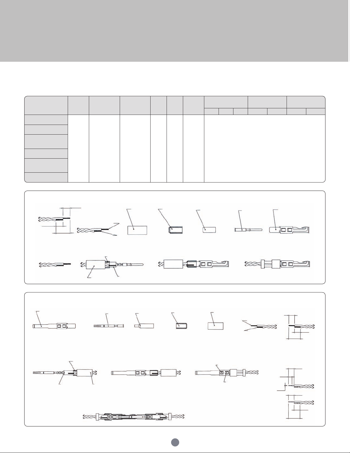
UTS Series
Cable reference
Contact
type
Male
contact
Female
contact
Crimp
tool
Die
set
Stop
bushing
Cable strip length
Inner conductor
crimp
Braid crimp
A B C g dim t dim g dim t dim
2#24 stranded mil w
16878 type B
Multi
piece
RMDXK10D28 R CDXK10D28 M10S-1J - - See assembly notice
2 #24 solid mil-w-76
type LW
2 #26 stranded mil w 76
type LW or mil w16878
type b&e
2 #28 solid mil-
w-81822/3
TWISTED PAIR 1/.201
SOLID M IL w 76 TYPE lw
OR MIL W 16878
twisted pair solid mil w
81822/3
Coaxial contacts
Twisted pair cable multipiece contact cabling
Female contact
±0.41
Strip lengths
of cable
7.95
±0.41
6.35
Conductor "W"
Outer hyring
YOC-074
Twisted pair adapter
YORK-090
Inner supporting
sleeve
RCDXB-055-1
Inner pin
RMD26L-1
Outer female contact
RCDX60-2
Male contact
Step 1: Step 2: Step 3:
Note : all dimensions are in mm
±0.41
13.49
Outer male contact
RMDX60-2
Inner supporting
sleeve
Conductor "X"
Step 1: Step 2: Step 3:
Twisted pair adapter
Outer hyring
Twisted pair adapter
Outer hyring
Supporting
sleeve
Inner socket
RFD26L-1
Inner supporting
sleeve
RMDXB-055-3
Twisted pair adapter
YORK-090
Outer hyring
YOC-074
Locking louver typical
Grounding louver typical
Conductor "Y"
Conductor "Z"
When using solid wire atten
conductor "X" and "Z" using
N24FL-1 die as shown
70
7.95
±0.41
5.94
±0.05
0.25
15.54
±0.41
15.54
Strip lengths
of cable
7.95
±0.41
7.54
±0.41
7.54
7.95
±0.41
±0.41
±0.41
Page 71
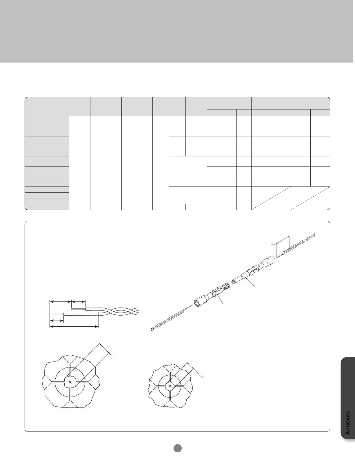
UTS Series
Cable reference
Contact
type
Male
contact
Female
contact
Crimp
tool
Die
set
Stop
bushing
Cable strip length
Inner conductor
crimp
Braid crimp
A B C g dim t dim g dim t dim
#28 7/.0036 per Hitachi
spec ec-711 (13-2820)
Mono
crimp
RMDX60-31D28
+ YORX090
RCDX60-31D28
+ YORX090
M10S-1J
S-80 S L-105 4.7 6.1 4.32
1.30 to
1.12
1.4 to
1.22
2.97 to
2.84
3.07 to
2.9
20218204 S-80 S L-105 3.94 6.1 3.16
1.30 to
1.17
1.4 to
1.22
2.97 to
2.84
3.07 to
2.79
#30 solid S-83 S L-105 4.7 6.1 4.06
1.22 to
1.12
1.35 to
1.22
2.97 to
2.84
3.12 to
2.95
#26 7/.0063 S-80 S L-105 4.7 6.1 4.06
1.30 to
1.17
1.4 to
1.22
2.97 to
2.84
3.07 to
2.9
#26 19/.004
M10SG8 ASSY'Y
TOOL DIE SET
STOP BUSH ING
M10S-1J TOOL
4.7 6.1 4.06
1.22 to
1.17
1.35 to
1.22
2.84 to
2.79
3.12 to
2.97
#24 7/.008 4.7 6.1 4.06
1.22 to
1.17
1.35 to
1.22
2.84 to
2.79
3.12 to
2.97
#24 19/.005 4.7 6.1 4.0 6
1.22 to
1.17
1.35 to
1.22
2.84 to
2.79
3.12 to
2.97
AWG26 (19x0.1)
M10SG8
crimping kit
4.7 6 4
AWG24 (7x0.2)
AWG24 (19x0.13)
AWG26 (7x0.16) S-80 SL-150
Twisted pair cable monocrimp contact cabling
• Select appropriate monocrimp coax twisted pair contact and cable combination.
• Select appropriate crimp tooling (hand tool, S-die set, stop bushing).
• Strip the twisted pair cable to the designated wire strip lengths.
• Insert the stripped cable into the contact. One cable is to be inserted into the
inside diameter of hyring, and pushed forwaerd into the inner contact. The
second cable is to be inserted between the outside diameter of hyring and the
inside diameter of the outer contact body.
• Crimp the contact.
Cable strip length
B
C
A
16 min.
Note : all dimensions are in mm
Braid crimp (G) to be measured
with die set fully closed
G
Inner conductor crimp (G) to be
measured with die set fully closed
71
See cable strip lengths
RMDX60
Male coax contact
RCDX60
Female coax contact
G
Annexes
Page 72
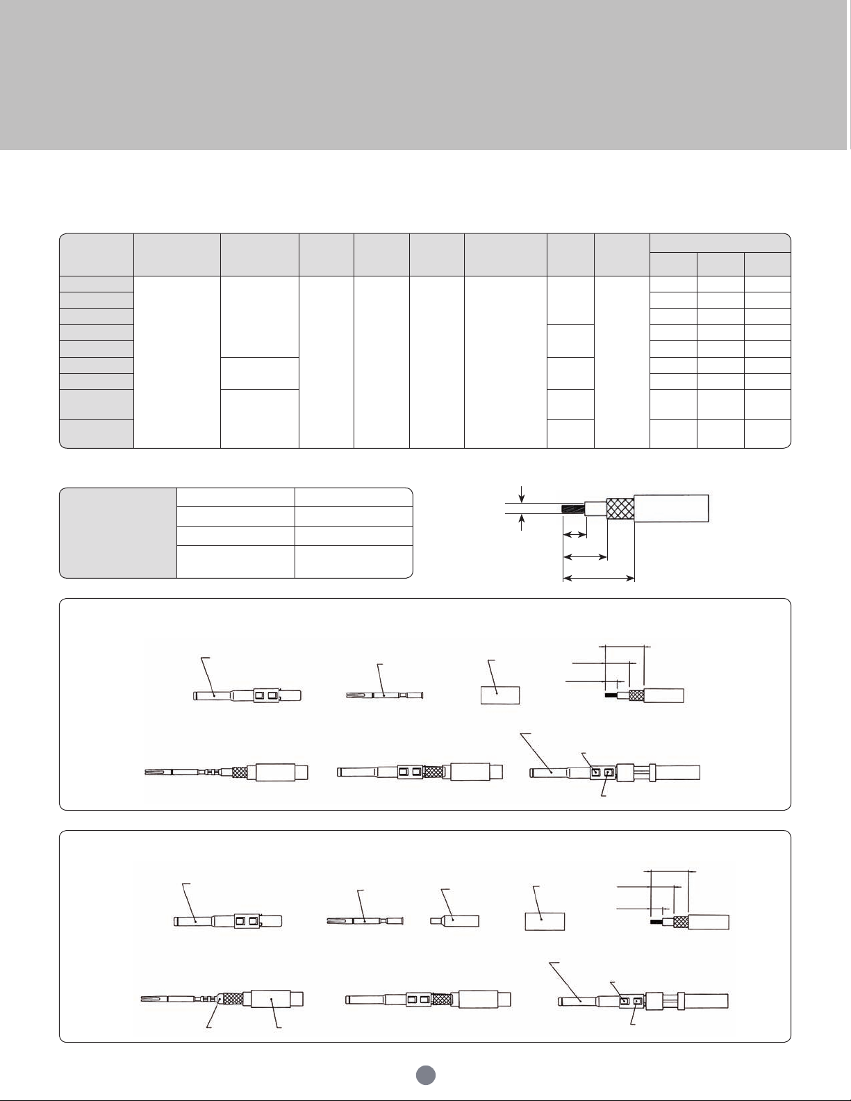
UTS Series
Cable
reference
Outer contact
Hyring com-
plementary
compoments
Crimp
tool
Die set
Stop
bushing
Inner
contact
Die set
Stop
bushing
Cable strip length
A B C
RG161U
Male:
RMDXK10D28
YOC074
M10S-1J S22-1 SL47-1 RFD26L1D28
S23D2
SL46D2
4.37 7.95 15.88
RG179 4.37 7.95 15.88
RG187U 4.37 7.95 15.88
RG188/U
S26D2
4.37 7.95 15.88
RG174/U 4.37 7.95 15.88
RG178A/U
YOC074 +
RMDXB0553
S23D2
7.54 9.12 17.53
RG196U 7.54 9.12 17.53
AMPHENOL
21-598
YOC074
- 4.37 7.95 15.88
surprenant
pn 8134
- 4.37 7.95 15.88
RMDXK10D28
includes
RMDX602D28 Body contact
RFD26L1D28 Inner contact
YOC-074 Outer hyring
RMDXB0553
Inner supporting
sleeve
Coaxial contacts
Multipiece male contact with coax cable
Multipiece kit details
Cable stip length
Dielectric
diameter
A
B
C
Contact assembly with dielectric diameter over 1.4mm - without inner supporting sleeve
±0.41
Outer male contact
RMDX60-2
Step 1:
- Assemble outer hyring onto cable
- Assemble inner socket to inner conductor and crimp
Inner socket
RFD26L-1
Step 2:
- Insert the assembly into the outer male contact
until the inner socket snaps into place
- The cable braid (shield) should now cover the
barrel of the outer male contact as shown
Outer hyring
YOC-074
Step 3:
- Slide outer hyring forward against spring and
crimp in place as shown
15.88
±0.41
7.95
±0.41
4.37
Locking louver typical
Grounding louver typical
Strip lengths
of cable
Contact assembly with dielectric diameter under 1.4mm - with inner supporting sleeve
±0.41
17.53
Outer male contact
RMDX60-2
Step 1:
- Assemble outer hyring onto cable
- Assemble supporting sleeve over dielectric and under braid
- Assemble inner socket to inner conductor, push back against
sleeve and crimp
Note : all dimensions are in mm
Supporting
sleeve
Outer hyring
Inner socket
RFD26L-1
Step 2:
- Insert the assembly into the outer male contact
until the inner socket snaps into place
- The cable braid (shield) should now cover the
barrel of the outer male contact as shown
72
Inner supporting
sleeve
RMDXB-055-3
Outer hyring
YOC-074
Step 3:
- Slide outer hyring forward against spring and
crimp in place as shown
±0.41
9.12
±0.41
7.54
Locking louver typical
Grounding louver typical
Strip lengths
of cable
Page 73
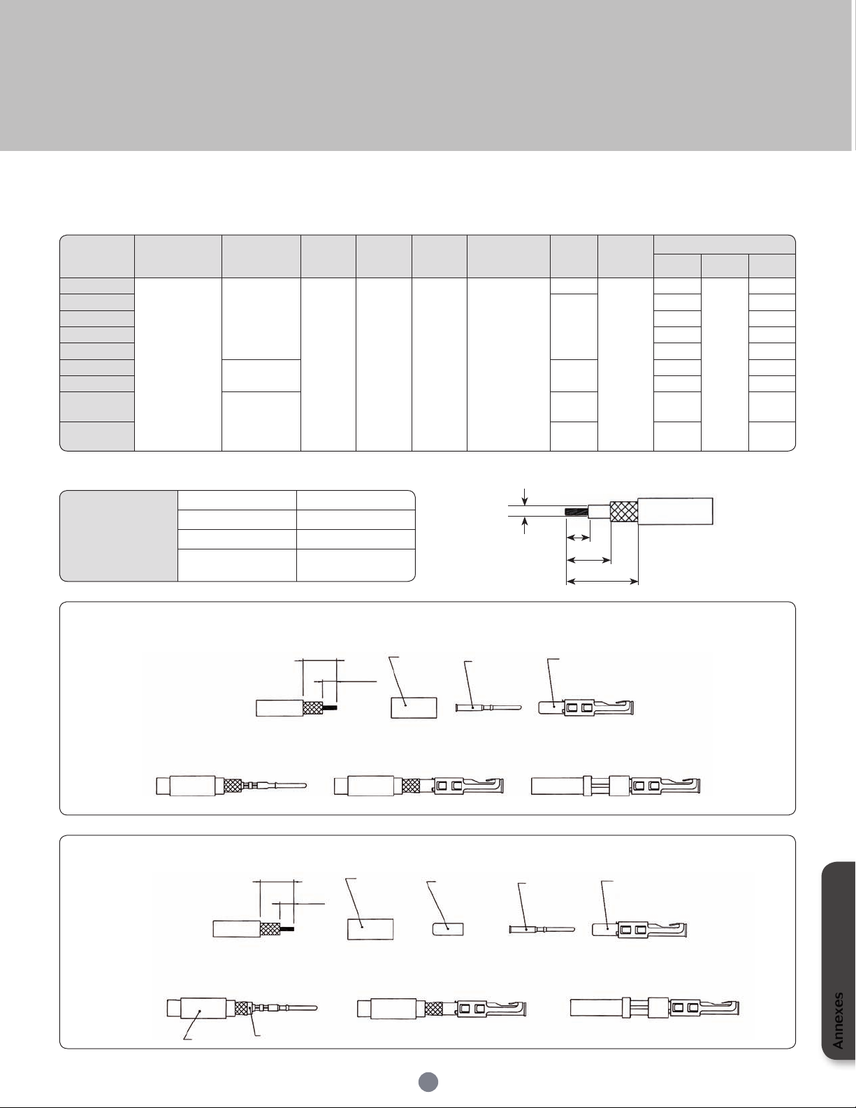
UTS Series
Cable
reference
Outer contact
Hyring com-
plementary
compoments
Crimp
tool
Die set
Stop
bushing
Inner
contact
Die set
Stop
bushing
Cable strip length
A B C
RG161U
Female:
RCDXK10D28
YOC074
M10S-1J S22-1 SL47-1 RMD26L1D28
S23D2
SL46D2
4.37
-
11.13
RG179
S23D2
4.37 11.13
RG187U 4.37 11.13
RG188/U 4.37 11.13
RG174/U 4.37 11.13
RG178A/U
YOC074 +
RMDXB0553
S23D2
6.35 11.13
RG196U 6.35 11.13
AMPHENOL
21-598
YOC074
- 4.37 11.13
surprenant
pn 8134
- 4.37 11.13
RCDXK10D28
includes
RCDX602D28 Body contact
RMD26L1D28 Inner contact
YOC-074 Outer hyring
RCDXB0553
Inner supporting
sleeve
Multipiece female contact with coax cable
Multipiece kit details Cable stip length
Dielectric
diameter
A
B
C
Contact assembly with dielectric diameter over 1.4mm - without inner supporting sleeve
±0.41
Strip lengths
of cable
Step 1:
- Assemble outer hyring onto cable
- Assemble inner pin to inner conductor and crimp
11.13
±0.41
4.37
Step 2:
- Insert the assembly into the outer female contact
until the inner pin snaps into place
- The cable braid (shield) should now cover the
barrel of the outer female contact as shown
Outer hyring
YOC-074
Inner pin
RMD26L-1
Outer female contact
RCDX60-2
Step 3:
- Slide outer hyring forward against spring and
crimp in place as shown
Contact assembly with dielectric diameter under 1.4mm - with inner supporting sleeve
±0.41
11.13
Strip lengths
Step 1:
- Assemble outer hyring onto cable
- Assemble supporting sleeve over dielectric and under braid
- Assemble inner pin to inner conductor, push back against
sleeve and crimp
Note : all dimensions are in mm
of cable
Outer hyring
Supporting
sleeve
6.35
±0.41
Outer hyring
YOC-074
Step 2:
- Insert the assembly into the outer female contact
until the inner pin snaps into place
- The cable braid (shield) should now cover the
barrel of the outer female contact as shown
Supporting sleeve
RCDXB-055-1
Inner pin
RMD26L-1
73
Outer female contact
RCDX60-2028
Step 3:
- Slide outer hyring forward against spring and
crimp in place as shown
Annexes
Page 74
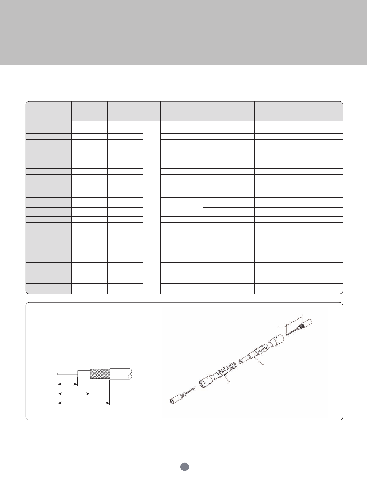
UTS Series
Cable
reference
Male
contact
Female
contact
Crimp
tool
Die
set
Stop
bushing
Cable strip length
Inner conductor
crimp
Braid crimp
A B C g dim t dim g dim t dim
CDC PIN22939200 R MDX60-46D28 RCDX60-16D28
M10S-1J
S-80 SL-105 4.19 5.97 8.51 1.30/1.17 1.40/1.22 2.77/2.64 3.02/2.84
CDC PIN22939200 R MDX60-46D28 RCDX60-16D28 S-87 S L-105 5.08 6.35 8.89 1.30/1.17 1.40/1.22 2.77/2.64 3.02/2.84
CDC PIN245670000 RMDX60-50D28 RCDX60-16D28 S-80 SL-105 5.08 6.35 8.89 1.30/1.17 1.40/1.22 2.97/2.84 3.12/2.95
KX21TVT (europe)
RG178 B/U
RMDX60-34D28 RC DX60-34D28 S-82 SL-105 5.08 6.35 8.89 1.30/1.17 1.32/1.17 2.84/2.74 3.07/2.9
RG178 / BU RMDX60-50D28 RCDX60-16D28 S-87 SL-105 5.08 6.35 8.89 1.30/1.17 1.40/1.22 2.77/2.64 3.02/2.84
ampex RM DX60-32D28 RCDX60-32D28 S-80 SL-105 5.08 6.35 11.68 1.30/1.17 1.40/1.22 2.97/2.84 3.12/2.95
TI PN 920580 RMDX60-24D28 RC DX60-24D28 S-82 SL-105 5.08 6.35 8.89 1.35/1.19 1.42/1.27 2.87/2.74 3.07/2.9
RG174/U RMDX60-32D28 RCDX60-32D28 S-80 SL-105 5.08 6.35 11.68 1.30/1.17 1.40/1.22 2.97/2.84 3.12/2.95
Honeywell PN
58000062
RMDX60-26D28 RC DX60-26D28 S-82 SL-105 5.08 6.35 8.89 1.35/1.19 1.42/1.27 2.87/2.74 3.07/2.9
RG188A /U RM DX60-36D28 RCDX60-36D28 S-80 SL-105 5.08 6.35 11.68 1.30/1.17 1.40/1.22 2.97/2.84 3.12/2.95
RG316/ U R MDX60-36D28 RCDX60-36D28 S-80 SL-105 5.08 6.35 11.68 1.30/1.17 1.40/1.22 2.97/2.84 3.12/2.95
PRD PN
247AS-C1123-001
RMDX60-18D28 RC DX60-18D28
M10SG8 ASSY'Y
TOOL DIE SET
STOP BUSH ING
M10S-1J TOOL
5.08 6.35 8.89 1.22/1.17 1.35/1.22 2.92/2.79 3.12/2.97
PRD PN 247AS-C1251 RMDX60-18D28 RC DX60-18D28 5.08 6.35 8.89 1.22/1.17 1.35/1.22 2.92/2.79 3.12/2.97
raychem 5024A3111 R MDX60-52D28 RC DX60-52D28 S-88 SL-105 5.08 6.35 11.68 1.37/1.27 1.45/1.32 2.92/2.79
raychem 5026e1614 RMDX60-36D28 RCDX60-36D28 M10SG8 ASSY'Y
TOOL DIE SET
STOP BUSH ING
M10S-1J TOOL
5.08 6.35 8.89 1.22/1.17 1.35/1.22 2.92/2.79 3.12/2.97
JUDD C15013010902 RMDX60-36D28 RCDX60-36D28 5.08 6.35 8.89 1.22/1.17 1.35/1.22 2.92/2.79 3.12/2.97
inner cond. #30,
braid diam 2.64
RMDX60-50D28 RC DX60-50D28 S-80 SL-105 5.1 6.35 8.9 - - - -
inner cond. #30,
braid diam 2.29
RMDX60-50D28 RC DX60-50D28 S-87 S L-105 4.2 6.35 8.5 - - - -
inner cond. #28,
braid diam 2.9
RMDX60-32D28 RC DX60-32D28 S-80 SL-105 5.1 6.35 11.7 - - - -
inner cond. #26,
braid diam 1.78
RMDX60-24D28 RC DX60-24D28 S-82 SL-105 5.1 6.35 8.9 - - - -
inner cond. #26,
braid diam 3.05
RMDX60-26D28 RC DX60-26D28 S-82 SL-105 5.1 6.35 8.9 - - - -
Coaxial contacts
Coax cable with monocrimp contact cabling
• Select appropriate cable and contact combination.
• Select appropriate crimp tooling (hand tool, S-die set, stop bushing).
• Strip coax cable to the designated wire strip lengths.
• Insert the stripped coax into the rear of the contact.
• Crimp the contact.
Cable strip length
A
B
C
74
See cable strip lengths
RCDX60
Female coax contact
RMDX60
Male coax contact
Page 75
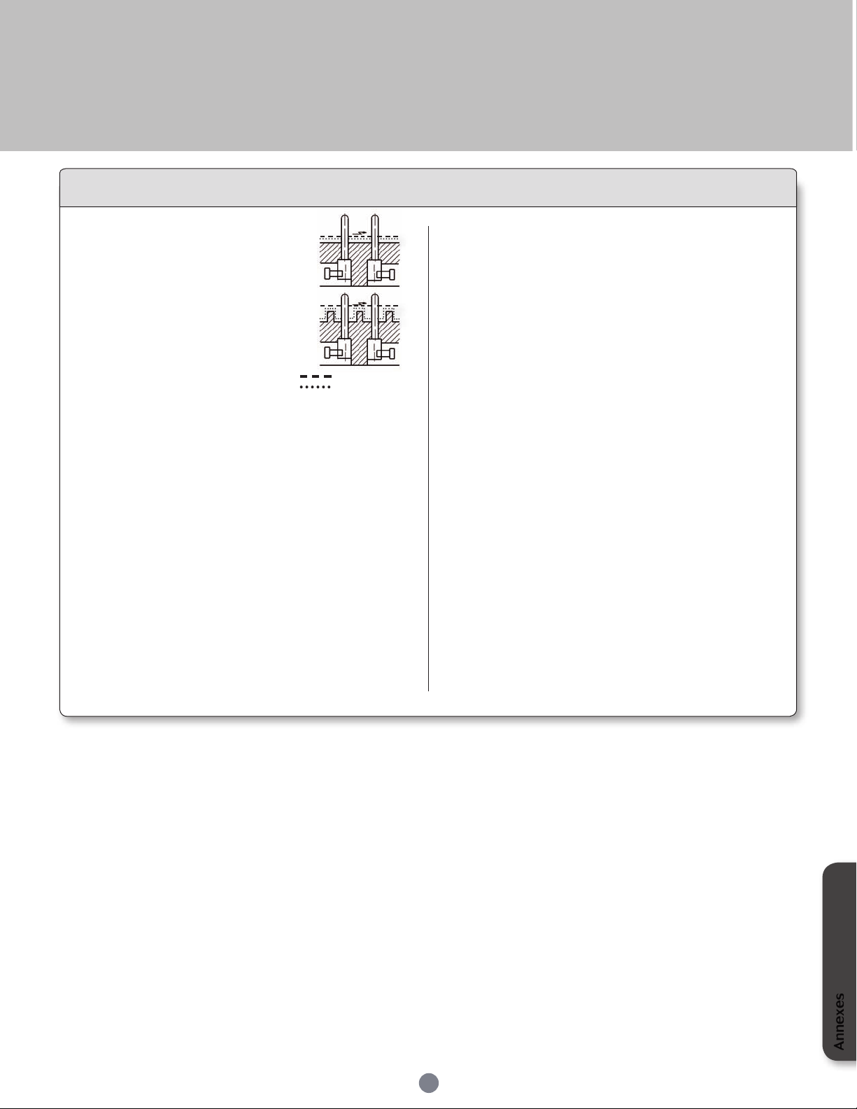
UTS Series
Glossary of terms
• Clearance
Per the IEC 60664-1 it is the shortest
distance between two conductive parts
even over the air.
• Creepage distance
Per the IEC 60664-1 it represents the
shortest distance along the surface
of the insulating material between two
conductive parts.
• Working voltage
Per the IEC 60664-1 it is the highest r.m.s. value of A.C. or D.C.
voltage across any particular insulation which can occur when the
equipment is supplied at rated voltage.
• Rated impulse voltage
Impulse withstands voltage value assigned by the manufacturer
to the equipment or to a part of it characterizing the specied
withstand capability of its insulation against transient overvoltage.
• Working current
It is the maximum continuous and not interrupted current able
to be carried by all contacts without exceeding the maximum
temperature of the insulating material.
Air gap
Creepage distance
• CTI (Comparative Tracking Index)
The CTI value is commonly used to characterize the electrical
breakdown properties of an insulating material. It allows users
to know the tendency to create creepage paths. This value
represents the maximum voltage after 50 drops of ammonium
chloride solution without any breakdown.
• RTI (Relative temperature Index):
Extract from ULs website:
“Maximum service temperature for a material, where a class of
critical property will not be unacceptably compromised through
chemical thermal degradation, over the reasonable life of an
electrical product, relative to a reference material having a
conrmed, acceptable corresponding performance dened RTI.
- RTI Elec: Electrical RTI, associated with critical electrical
insulating properties.
- RTI Mech Imp: Mechanical Impact RTI, associated with
critical impact resistance, resilience and exibility
properties.
- RTI Mech Str: Mechanical Strength (Mechanical
without Impact) RTI, associated with critical
mechanical strength where impact resistance,
resilience and exibility are not essential”
• Transient voltage
Extract from the IEC 60664-1: Short duration overvoltage of a
few millisecond or less, oscillatory or non-oscillatory, usually
highly damped.
Annexes
75
Page 76
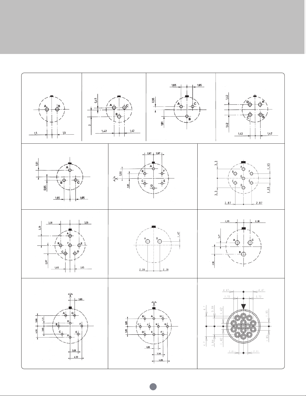
UTS Series
Drilling patterns (terminations viewed from male rear face, soldering side)
8D3A/8D988D3 8D48D2
8D33
10D98 12D2
12D1012D8
10D710D6
12D3
12D14
76
Page 77
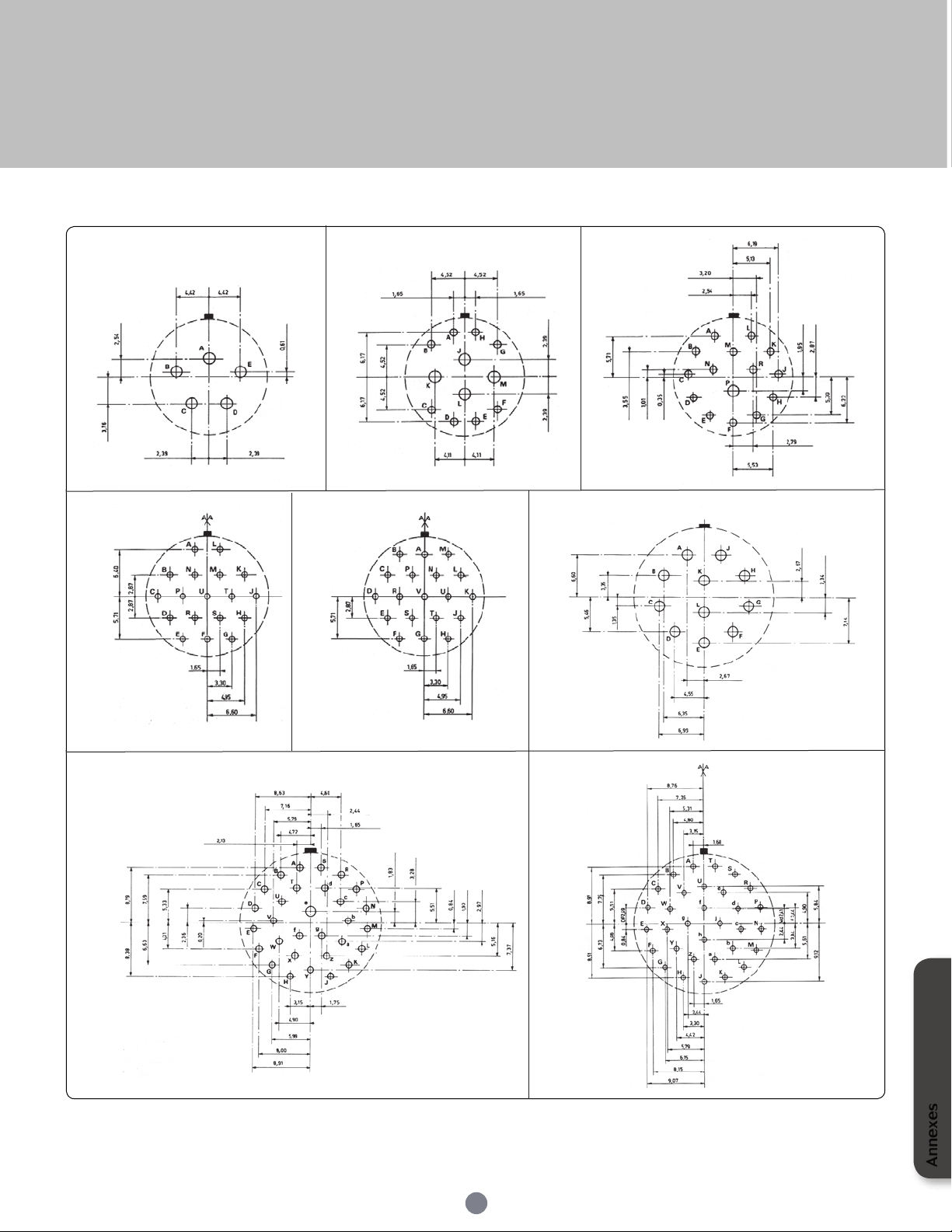
UTS Series
14D5 14D1514D12
14D18 14D19
18D30
18D11
18D32
77
Annexes
Page 78
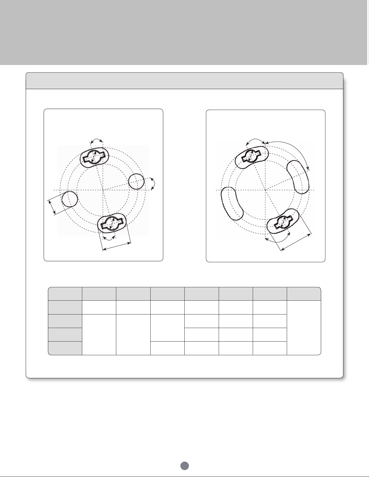
UTS Series
Shell size Angle A Angle B Angle C
Ø Internal
diameter D1
Diameter D2
Ø External
diameter D3
Ø E
8 15° 15° 15° 13.5 17.7 22
3.1
10
22° 68°
30°
17 21.25 25.5
12 22 26.25 30.5
14 22° 24 32.5
Stand off dimensions - Drilling pattern (PCB view)
4mm
D3
D2
D1
Size 8
A
E
E
C
7.5mm
Size 10 to 14
A
B
E
D3
D2
B
D1
E
C
10mm
Note : all dimensions are in mm
78
Page 79
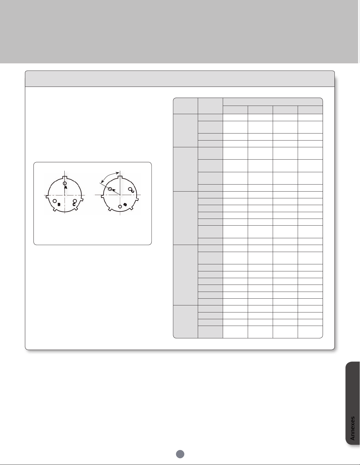
UTS Series
Shell
size
Layout
Discrimination keys degrees
W X Y Z
8
8E2 58° 122°
8E3
8E3A
60° 210°
8E4 45°
8E33 90°
10
102W2
103
104
106
45°
10E6
10E7
90°
10E98 90° 180° 240° 270°
12
12E2
12E3 180°
124
128 26°
12E8 90° 112° 203° 292°
1210
12E10
60° 155° 270° 295°
12E14 45°
14
14E5 40° 92° 184° 273°
142G1
147
1412 60°
14E12 43° 90°
14E15 17° 110° 155° 234°
14E18 15° 90° 180° 270°
1419 30° 165° 315°
14E19 30° 165° 315°
18
18E11 62° 119° 241° 340°
1823 158° 270°
18E30 180° 193° 285° 350°
1832
18E32
85° 138° 222° 265°
Discrimination/Keying methods
In applications where similar connectors are used
next to each other, mismatching can be a reason for
disturbances, system failure or even danger to operating
personnel.
To eliminate mismatching, all TRIM TRIO
can be equipped with discrimination keys, which
offer unlimited possibilities for an error avoiding
interconnection system.
The other way around is to rotate the insert into the shell.
®
connectors
N (Normal)
Note: Insert rotated in body
(viewed from front face of male insert)
Connectors with rotated inserts can be ordered by
adding the suffix W, X, Y or Z to the standard part
number.
Annexes
79
Page 80
www.souriau.com
www.souriau-industrial.com
INDUTSCAUS04EN © Copyright SOURIAU April 2010 - All information in this document presents only general particulars and shall not form part of any contract. All rights reserved to SOU RIAU for changes without prior notication or public announcement. Any duplication is prohibited, unless approved in writing.
 Loading...