

QUICK START GUIDE
Defense Center 750
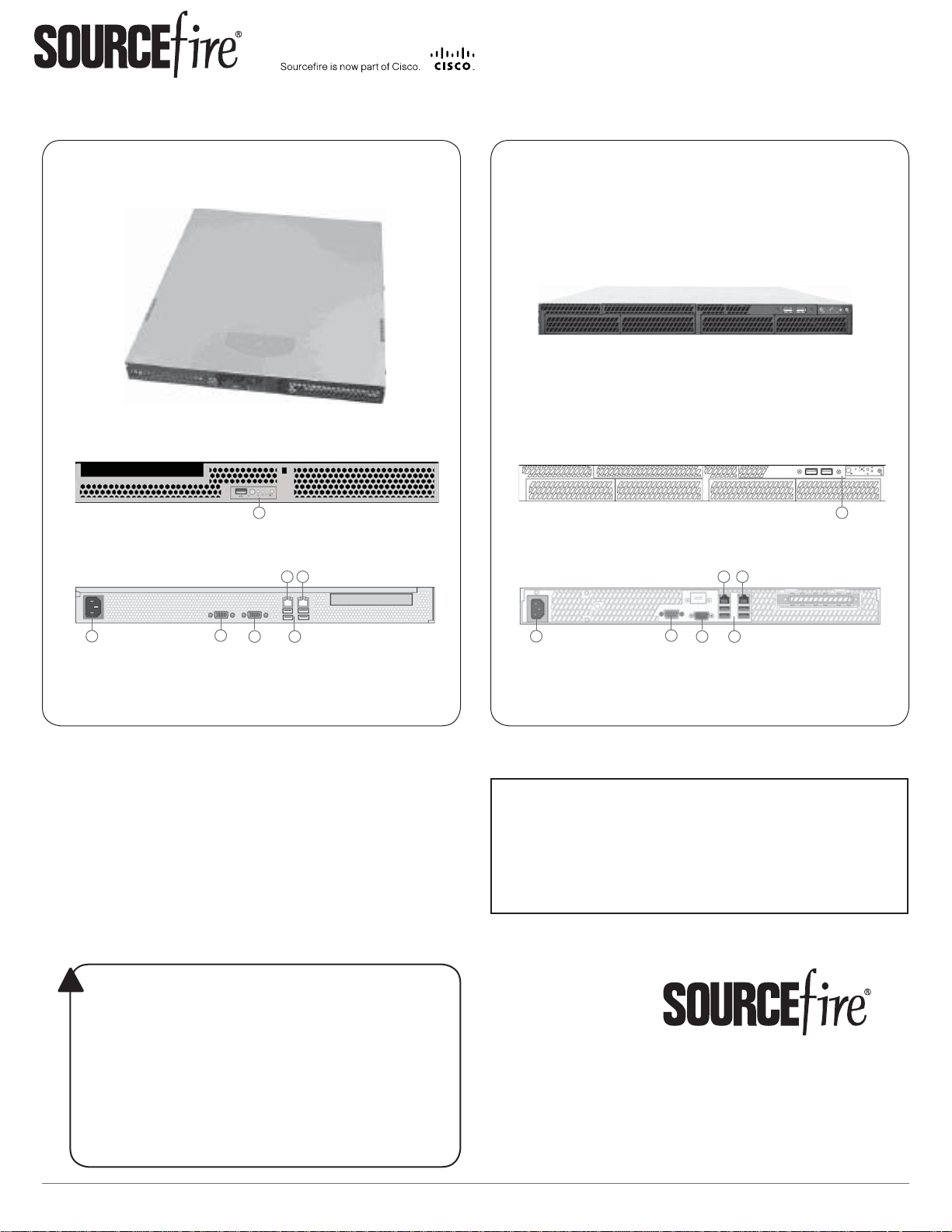
DC750 (Rev 1)
Front
(A) Front Panel Controls and USB Port
Back
DC750 (Rev 2)
Front
A
(A) Front Panel Controls and USB Ports
Back
E
F
E
F
A
C
D
B
(B) Power Supply
(C) Serial Port
(D) VGA Port
G
(E) Management Interface
(F) Alternate eStreamer Interface
(G) USB Ports
Included items:
Sourcefi re DC750 (Rev 1) or DC750 (Rev 2)•
one power cord•
one straight-through Cat 5e Ethernet cable•
rack-mounting kit•
Required items:
fl athead and Phillips screwdrivers for the •
rack-mounting kit
laptop or monitor and keyboard to connect •
directly to the Defense Center
WARNING!
!
This Sourcefi re appliance should be installed and maintained by
qualifi ed personnel only. Keep in mind the following safety
information to avoid system damage or personal injury:
Remove all factory packaging before using the appliance.•
Provide adequate ventilation to prevent overheating. Do not •
cover or block vents, or otherwise enclose the appliance.
The appliance must be properly grounded when connecting •
power to the power outlet.
At all times, keep the chassis area free from dust.•
Lifting the chassis for rack installation may require two people, •
as the unit is heavy.
To avoid electrical shock, do not open or remove the chassis •
covers or metal parts without proper instruction.
C
D
B
(B) Power Supply
(C) Serial Port
(D) VGA Port
G
(E) Management Interface
(F) Alternate eStreamer Interface
(G) USB Ports
Thank you for choosing Sourcefi re.
Before installing this device, download and follow the
instructions in the Sourcefi re Support Welcome Kit
(https://support.sourcefi re.com) to get started with
Sourcefi re Support, and to set up your Customer
Center account.
9770 Patuxent Woods Drive
Columbia, MD 21046 USA
800.917.4134 | +1.410.423.1901
support@sourcefi re.com
©2014 Cisco and/or its affi liates.
All rights reserved.
Quick Start Guide - DC750
Page 1 of 4
2014-5.2-3

https:// 192.168.45.45
DC750
INSTALLATION and CONFIGURATION
Installing the Hardware
Mount the Defense Center in your rack using the instructions included with the rack
mounting kit.
To install the Defense Center:
Connect the power cord to the Defense Center and plug it into a power source.1.
Turn on the Defense Center using the power button on the front panel. 2.
Connect an Ethernet cable from the management interface to a protected network segment. The default 3.
IP address of the management interface is 192.168.45.45 with a netmask of 255.255.255.0.
Confi gure the management interface as instructed below.4.
Confi guring the Management Interface
Connect the management interface to a secure internal management network that is
protected from unauthorized access.
Use either of two options for specifying the management interface and other network
settings: connect a laptop to the management interface (IPv4 addresses only), or connect a
monitor and keyboard to the Defense Center (IPv4 or IPv6 addresses).
Using the Management Interface
Specify the management interface network settings by connecting a laptop directly to
the management interface.
To confi gure using the management interface:
Using the supplied Ethernet cable, connect the network interface on a local host (for example, a 1.
laptop computer) to the management interface on the Defense Center.
Create an IP alias address for the 192.168.45.0 subnet on the local host, making sure that you do 2.
not use the same IP address as the default IP address of the management interface (192.168.45.45).
Note that each operating system has its own procedure for creating an alias.
Use your web browser to navigate to the Defense Center’s default IP address:3.
https:// 192.168.45.45
The login page appears.
Log into the web interface using4. admin as the user and Sourcefi re as the password and
continue with Performing the Initial Setup on page 3. Note that the password is case-sensitive.
Quick Start Guide - DC750
Page 2 of 4
2014-5.2-3

sudo /usr/local/sf/bin/confi gure-network
Management IP address?
10.2.2.20
Management netmask?
255.255.255.0
Management gateway?
10.2.1.1
Are these settings correct: (y or n)?
DC750
CONFIGURATION (continued) and INITIAL SETUP
Confi guring the Management Interface, continued
Using a Monitor and Keyboard
Specify the management interface network settings by connecting a monitor and
keyboard to the back of the Defense Center.
To confi gure using a monitor and keyboard:
Using the supplied Ethernet cable, connect the management interface on the back of the Defense 1.
Center to a protected management network.
Connect the monitor to the VGA port and the keyboard to one of the USB ports.2.
Log into the command line interface using3. admin as the user and Sourcefi re as the password.
Note that the password is case-sensitive.
Run the following script:4.
sudo /usr/local/sf/bin/confi gure-network
The following prompt (appended with the current value) appears:
Management IP address?
Enter the IP address you want to assign to the management interface or press Enter to accept the 5.
current value. For example:
10.2.2.20
The following prompt (appended with the current value) appears:
Management netmask?
Enter the netmask for the interface’s IP address or press Enter to accept the current value. For 6.
example:
255.255.255.0
The following prompt (appended with the current value) appears:
Management gateway?
Enter the gateway for the interface’s IP address or press Enter to accept the current value. For 7.
example:
10.2.1.1
The following prompt appears:
Are these settings correct: (y or n)?
If the settings are correct, type8. y and press Enter to accept the settings and continue.
If the settings are incorrect, type n and press Enter. You are prompted to enter the information
again.
After you have accepted the settings, log out of the shell.
Performing the Initial Setup
Complete the initial setup through the web interface. To access the web interface, browse
to the IP address you confi gured in the previous procedure.
Refer to the Sourcefi re 3D System Installation Guide for information to guide you through
the start-up pages for the Defense Center.
Quick Start Guide - DC750
Page 3 of 4
2014-5.2-3

DC750
A USB port
B Power button
C System status LED
D Power LED
E Fixed disk drive status LED
F NIC 1 activity status LED
G NIC 2 activity status LED
A ID button with ID LED
B Non-maskable interrupt button
C NIC activity status LEDs
D Reset button
E Fixed disk drive status LED
F Power button with power LED
G System status LED
LEDs, SPECIFICATIONS, REGULATORY, and SECURITY
LEDs
Front Panel and Front Panel LEDs
DC750 (Rev 1)
A
B
F
D
E
C
A USB port
G
B Power button
C System status LED
D Power LED
E Fixed disk drive status LED
F NIC 1 activity status LED
G NIC 2 activity status LED
LED Color Indications
System status A green light indicates that the system is operating normally.
Power A green light indicates there is power.
Hard Drive Activity A blinking green light indicates that the fi xed disk drive is active.
NIC Activity A blinking green light indicates there is activity.
A blinking green light indicates that the system is operating in a degraded condition.
DC750 (Rev 1) only: A blinking amber light indicates that the system is in a non-critical error condition.
DC750 (Rev 1) only: An amber light indicates that the system is in a critical or non-recoverable error condition.
No light indicates POST/system stop.
IMPORTANT! - DC750 (Rev 1) only
Amber status light takes precedence over green. When amber is on or blinking, green is off.
A blinking green light indicates the system is sleeping.
No light indicates there is no power.
DC750 (Rev 1) only: An amber light indicates there is a fi xed disk drive fault.
No light indicates either there is no drive activity, or the system is powered off or sleeping.
No light indicates there is no activity.
Management Interface LEDs
DC750 (Rev 2)
A
B
A ID button with ID LED
D
E
C
G
F
B Non-maskable interrupt button
C NIC activity status LEDs
D Reset button
E Fixed disk drive status LED
F Power button with power LED
G System status LED
LED Description
Left (Link) Indicates whether the link is up. If the LED is on, the link is up; if the LED is off, there is no link.
Right (Activity) Indicates activity on the port. A blinking LED indicates activity; if the LED is off, there is no activity.
Hardware Specifi cations
Physical and Environmental Parameters
Parameter DC750 (Rev 1) DC750 (Rev 2)
Form Factor 1U 1U
Dimensions (D x W x H) 20.0” x 16.93” x 1.67” (50.8 cm x 43.0 cm x 4.24 cm) 21.8” x 17.25” x 1.67” (55.37 cm x 43.82 cm x 4.24 cm)
Max Weight 33 lbs (15 kg) 33 lbs (15 kg)
Power Supply 350 W power supply at 120 VAC
Operating Temperature 50°F to 95°F (10°C to 35°C) with the maximum rate of change
Non-Operating Temperature -40°F to +158°F (-40°C to +70°C) -40°F to +158°F (-40°C to +70°C)
Non-Operating Humidity 90%, non-condensing at 95°F (35°C) 90%, non-condensing at 82.4°F (28°C)
Acoustic Noise <7.0 dBA (rack mount) in an idle state at typical offi ce ambient
Operating Shock No errors with half a sine wave shock of 2G (with 11
Package Shock Operational after 24” (61 cm) free fall; cosmetic damage may
Air Flow Front to back Front to back
ESD +/- 12kV for air discharge and 8 K for contact +/- 12kV for air discharge and 8 K for contact
System Cooling Requirements 1660 BTU/hour 1660 BTU/hour
9.5 Ampere max. at 110 Volts, 50/60 Hz
4.75 Ampere max. at 220 volts, 50/60 Hz
not to exceed 18°F (10°C)
temperature
millisecond duration)
be present (chassis weight: 40-80 lbs / 18-36 kg)
Regulatory Conformance
This Sourcefi re appliance conforms to multiple national and international standards. For a full list of regulatory compliance, see the
Sourcefi re 3D System Installation Guide
.
Security Considerations
Before you install your appliance, Sourcefi re recommends that you consider the following:
Locate your appliance in a lockable rack within a secure location that prevents access by unauthorized personnel.•
Allow only trained and qualifi ed personnel to install, replace, administer, or service the appliance.•
Always connect the management interface to a secure internal management network that is protected from unauthorized access.•
250 W power supply at 120 VAC
6.0 Ampere max. at 110 Volts, 50/60 Hz
3.0 Ampere max. at 220 volts, 50/60 Hz
50°F to 95°F (10°C to 35°C) with the maximum rate of change
not to exceed 18°F (10°C)
<7.0 dBA (rack mount) in an idle state at typical offi ce ambient
temperature
No errors with half a sine wave shock of 2G (with 11
millisecond duration)
Operational after 24” (61 cm) free fall; cosmetic damage may
be present (chassis weight: 40-80 lbs / 18-36 kg)
Quick Start Guide - DC750
Page 4 of 4
2014-5.2-3
 Loading...