


3D Sensor
Installation Guide
Version 4.10.3

Terms of Use Applicable to the User Documentation
The legal notices, disclaimers, terms of use, and other information contained herein (the “terms”) apply only to
the information discussed in this documentation (the “Documentation”) and your use of it. These terms do not
apply to or govern the use of websites controlled by Sourcefire, Inc. or its subsidiaries (collectively,
“Sourcefire“) or any Sourcefire-provided products. Sourcefire products are available for purchase and subject
to a separate license agreement and/or terms of use containing very different terms and conditions.
Terms of Use and Copyright and Trademark Notices
The copyright in the Documentation is owned by Sourcefire and is protected by copyright and other intellectual
property laws of the United States and other countries. You may use, print out, save on a retrieval system, and
otherwise copy and distribute the Documentation solely for non-commercial use, provided that you (i) do not
modify the Documentation in any way and (ii) always include Sourcefire's copyright, trademark, and other
proprietary notices, as well as a link to, or print out of, the full contents of this page and its terms.
No part of the Documentation may be used in a compilation or otherwise incorporated into another work or with
or into any other documentation or user manuals, or be used to create derivative works, without the express
prior written permission of Sourcefire. Sourcefire reserves the right to change the terms at any time, and your
continued use of the Documentation shall be deemed an acceptance of those terms.
SOURCEFIRE®, SNORT®, CLAMAV®, SOURCEFIRE DEFENSE CENTER®, SOURCEFIRE 3D®, RNA®, RUA®,
SECURITY FOR THE REAL WORLD®, the Sourcefire logo, the Snort and Pig logo, the ClamAV logo, Sourcefire
IPS, RAZORBACK, Sourcefire Master Defense Center, DAEMONLOGGER, and certain other trademarks and
logos are trademarks or registered trademarks of Sourcefire, Inc. in the United States and other countries. Other
company, product and service names may be trademarks or service marks of others.
© 2004 - 2013 Cisco and/or its affiliates. All rights reserved.
Disclaimers
THE DOCUMENTATION AND ANY INFORMATION AVAILABLE FROM IT MAY INCLUDE INACCURACIES OR
TYPOGRAPHICAL ERRORS. SOURCEFIRE MAY CHANGE THE DOCUMENTATION FROM TIME TO TIME.
SOURCEFIRE MAKES NO REPRESENTATIONS OR WARRANTIES ABOUT THE ACCURACY OR SUITABILITY OF
ANY SOURCEFIRE-CONTROLLED WEBSITE, THE DOCUMENTATION AND/OR ANY PRODUCT INFORMATION.
SOURCEFIRE-CONTROLLED WEBSITES, THE DOCUMENTATION AND ALL PRODUCT INFORMATION ARE
PROVIDED “AS IS” AND SOURCEFIRE DISCLAIMS ANY AND ALL EXPRESS AND IMPLIED WARRANTIES,
INCLUDING BUT NOT LIMITED TO WARRANTIES OF TITLE AND THE IMPLIED WARRANTIES OF
MERCHANTABILITY AND/OR FITNESS FOR A PARTICULAR PURPOSE. IN NO EVENT SHALL SOURCEFIRE BE
LIABLE TO YOU FOR ANY DIRECT, INDIRECT, INCIDENTAL, SPECIAL, EXEMPLARY, PUNITIVE, OR
CONSEQUENTIAL DAMAGES (INCLUDING BUT NOT LIMITED TO PROCUREMENT OF SUBSTITUTE GOODS OR
SERVICES, LOSS OF DATA, LOSS OF PROFITS, AND/OR BUSINESS INTERRUPTIONS), ARISING OUT OF OR IN
ANY WAY RELATED TO SOURCEFIRE-CONTROLLED WEBSITES OR THE DOCUMENTATION, NO MATTER HOW
CAUSED AND/OR WHETHER BASED ON CONTRACT, STRICT LIABILITY, NEGLIGENCE OR OTHER TORTUOUS
ACTIVITY, OR ANY OTHER THEORY OF LIABILITY, EVEN IF SOURCEFIRE IS ADVISED OF THE POSSIBILITY OF
SUCH DAMAGES. BECAUSE SOME STATES/JURISDICTIONS DO NOT ALLOW THE EXCLUSION OR LIMITATION
OF LIABILITY FOR CONSEQUENTIAL OR INCIDENTAL DAMAGES, THE ABOVE LIMITATIONS MAY NOT APPLY TO
YOU.
The Documentation may contain “links” to websites that are not created by, or under the control of Sourcefire.
Sourcefire provides such links solely for your convenience, and assumes no responsibility for the availability or
content of such other sites.
2014-Jan-15 12:06

Table of Contents
Chapter 1: Before You Begin......................................................................... 7
IPS Installation Considerations ............................................................................. 8
RNA Installation Considerations ........................................................................... 9
RUA Installation Considerations ......................................................................... 10
Typical 3D Sensor Deployments ......................................................................... 11
Deploying a Multi-Port 3D Sensor.......................................................... 15
Other Deployment Options ................................................................................ 18
Integrating with VPNs ............................................................................ 18
Detecting Intrusions on Other Points of Entry ....................................... 18
Deploying in Multi-Site Environments.................................................... 20
Integrating 3D Sensors with RNA within Complex Networks ............... 21
Understanding Detection Engines and Interface Sets........................................ 22
Understanding Detection Resources and 3D Sensor Models ............... 23
Comparing Inline and Passive Interface Sets......................................... 25
Connecting Sensors to Your Network................................................................. 25
Using a Hub ........................................................................................... 26
Using a Span Port .................................................................................. 26
Using a Network Tap.............................................................................. 26
Issues for Copper Cabling in Inline Deployments .................................. 27
Special Case: Connecting 8000 Series Devices .................................... 29
Using a Sourcefire Defense Center .................................................................... 29
Communication Ports ......................................................................................... 31
Version 4.10.3 Sourcefire 3D Sensor Installation Guide 3

Table of Contents
Chapter 2: Installing a 3D Sensor .............................................................. 33
Included Items .................................................................................................... 34
Security Considerations ...................................................................................... 34
Identifying the Management and Sensing Interfaces......................................... 35
Sourcefire 3D Sensor 500/1000/2000 ................................................... 35
Sourcefire 3D Sensor 2100/2500/3500/4500......................................... 36
Sourcefire 3D Sensor 6500.................................................................... 38
Sourcefire 3D Sensor 7010/7020/7030 .................................................. 42
Sourcefire 3D Sensor 7110/7120 ........................................................... 42
Sourcefire 3D Sensor 8120/8130/8140 .................................................. 45
Sourcefire 3D Sensor 8250/8260/8270/8290......................................... 48
Sourcefire 3D Sensor 9900.................................................................... 53
Using 3D Sensors in a Stacked Configuration .................................................... 55
Connecting 3D9900 Sensors................................................................. 56
Connecting 3D8140 Sensors ................................................................. 58
Connecting 3D8250/8260/8270/8290 Sensors ...................................... 58
Using the 8000 Series Stacking Cable................................................... 62
Installing the 3D Sensor in a Rack ...................................................................... 62
Configuring the Management Interface.............................................................. 64
Using the Management Interface .......................................................... 65
Using a Monitor and Keyboard............................................................... 66
Using the LCD Panel.............................................................................. 68
Using the Command Line Interface ....................................................... 71
Performing the Initial Setup ................................................................................ 72
Redirecting Console Output ............................................................................... 75
Testing an Inline Fail-Open Interface Installation ................................................ 76
Checking for Updates ......................................................................................... 78
Chapter 3: Using the LCD Panel ................................................................. 79
Understanding the LCD Panel ............................................................................ 80
Understanding LCD Panel Modes ...................................................................... 80
Initial Setup/Network Configuration ....................................................... 81
Idle Display ............................................................................................ 82
Error Alert .............................................................................................. 83
System Status........................................................................................ 83
Using the Multi-Function Keys............................................................................ 85
Resetting the Network Configuration ................................................................. 87
Adjusting the Brightness and Contrast on the LCD Panel .................................. 88
Version 4.10.3 Sourcefire 3D Sensor Installation Guide 4

Table of Contents
Chapter 4: Hardware Specifications......................................................... 89
Rack and Cabinet Mounting Options .................................................................. 89
Sourcefire 3D Sensor 500/1000/2000 Specifications ......................................... 90
Chassis Front View ................................................................................ 90
Chassis Rear View ................................................................................. 92
Physical and Environmental Parameters................................................ 93
Sourcefire 3D Sensor 2100/2500/3500/4500 Specifications .............................. 94
Chassis Front View ................................................................................ 94
Chassis Rear View ............................................................................... 100
Physical and Environmental Parameters.............................................. 102
Sourcefire 3D Sensor 6500 Specifications ....................................................... 103
Chassis Front View .............................................................................. 103
Chassis Rear View ............................................................................... 109
Physical and Environmental Parameters............................................... 111
Sourcefire 3D Sensor 7010/7020/7030 Specifications ...................................... 112
Chassis Front View .............................................................................. 113
Chassis Rear View ............................................................................... 118
Physical and Environmental Parameters.............................................. 119
Sourcefire 3D Sensor 7110/7120 Specifications ............................................... 120
Chassis Front View .............................................................................. 120
Chassis Rear View ............................................................................... 126
Physical and Environmental Parameters.............................................. 128
Sourcefire 3D Sensor 8120/8130/8140 Specifications ...................................... 130
Chassis Front View .............................................................................. 130
Chassis Rear View ............................................................................... 138
Physical and Environmental Parameters.............................................. 140
Sourcefire 3D Sensor 8250/8260/8270/8290 Specifications ............................ 142
Chassis Front View .............................................................................. 143
Chassis Rear View ............................................................................... 152
Physical and Environmental Parameters.............................................. 154
Sourcefire 3D Sensor 9900 Specifications ....................................................... 156
Chassis Front View .............................................................................. 156
Chassis Rear View ............................................................................... 162
Physical and Environmental Parameters.............................................. 165
Chapter 5: Restoring a 3D Sensor to Factory Defaults......................... 166
Using an ISO File to Restore Your System ....................................................... 167
Obtaining the Restore ISO File ............................................................ 168
Using a Restore USB Drive.................................................................. 168
Using an Internal Flash Drive ............................................................... 170
Completing the Restore Process ......................................................... 171
Updating the Restore USB Drive ...................................................................... 175
Scrubbing the Contents of the Hard Drive........................................................ 176
Version 4.10.3 Sourcefire 3D Sensor Installation Guide 5

Table of Contents
Chapter 6: Safety and Regulatory Information ...................................... 177
General Safety Guidelines ................................................................................ 177
Safety Warning Statements.............................................................................. 179
Regulatory Information ..................................................................................... 182
Sourcefire 3D Sensor 500/1000/2000 Information .............................. 183
Sourcefire 3D Sensor 2100/2500/3500/4500 Information ................... 184
Sourcefire 3D Sensor 6500/9900 Information ..................................... 185
Sourcefire 3D Sensor 7000 Series Information ................................... 186
Sourcefire 3D Sensor 8000 Series Information ................................... 189
Waste Electrical and Electronic Equipment Directive (WEEE) .......................... 193
Chapter 7: Power Requirements for Sourcefire 3D Sensors............... 194
Warnings and Cautions..................................................................................... 194
Interface Connections.......................................................................... 194
Static Control ....................................................................................... 195
3D7010/7020/7030............................................................................................ 195
Installation ........................................................................................... 195
Grounding/Earthing Requirements ..................................................... 196
3D7110/7120..................................................................................................... 197
Installation ........................................................................................... 197
Grounding/Earthing Requirements ..................................................... 198
3D8120/8130/8140 and 3D8250/8260/8270/8290 ............................................ 199
AC Installation ..................................................................................... 199
DC Installation...................................................................................... 201
Grounding/Earthing Requirements ..................................................... 202
For Assistance .................................................................................................. 204
Version 4.10.3 Sourcefire 3D Sensor Installation Guide 6

Chapter 1
Before You Begin
This guide describes how to install and set up the Sourcefire 3D Sensor.
Depending on which Sourcefire 3D System products you have licensed, a
Sourcefire 3D Sensor can include:
• IPS, the intrusion detection and prevention component
• RNA, the Real-time Network Awareness component
• RUA, the Real-time User Awareness component
• any two components, or all three
Each of the components is described in detail in the Sourcefire 3D System User
Guide. You can install a 3D Sensor with the IPS component as a standalone
appliance, but if you want to use RNA or RUA, you must use the 3D Sensor with
a Defense Center. Note that some models of the 3D Sensor do not support every
combination of components. See Understanding Detection Resources and
3D Sensor Models on page 23 for more information.
Before you install a Sourcefire 3D Sensor, you should consider how your network
is configured and how you want to deploy the various components of the
Sourcefire 3D System within it.
Version 4.10.3 Sourcefire 3D Sensor Installation Guide 7

Before You Begin
IPS Installation Considerations
This chapter describes some of the considerations for deploying a 3D Sensor,
including:
• the concept of the detection engine and the modes in which you can deploy
detection engines on the 3D Sensor: passive or inline
• your goals in deploying sensors that use RNA to perform network discovery
and vulnerability assessment, as well as your goals in deploying sensors
that use IPS to detect and prevent attacks on your network assets
• deployment issues, such as which network segments you want to monitor
with your 3D Sensors, and why
• how you will physically connect the sensors to your network, taking into
account any special network configuration factors, such as firewall
placement, VPN deployments
• whether you will use a Sourcefire Defense Center to aggregate and
correlate RNA and intrusion events
See the following sections for more information:
• IPS Installation Considerations on page 8
• RNA Installation Considerations on page 9
• RUA Installation Considerations on page 10
• Typical 3D Sensor Deployments on page 11
• Other Deployment Options on page 18
• Understanding Detection Engines and Interface Sets on page 22
• Connecting Sensors to Your Network on page 25
• Using a Sourcefire Defense Center on page 29
Chapter 1
IPS Installation Considerations
IPS is the intrusion prevention and detection component of the Sourcefire 3D
System. Before you install a 3D Sensor with IPS, you should consider how your
network is configured and how you want to deploy the various components of the
Sourcefire 3D System within it.
Every network architecture is different, and every enterprise has different security
needs. This section lists some of the factors you should consider as you
formulate your deployment plans and includes a description of how the Sourcefire
3D System can help you meet common network security goals.
Version 4.10.3 Sourcefire 3D Sensor Installation Guide 8

Before You Begin
RNA Installation Considerations
Your deployment decisions for 3D Sensors with IPS will be based on a variety of
factors. Answering these questions can help you understand the vulnerable areas
of your network and clarify your intrusion detection and prevention needs:
• Will you be deploying your 3D Sensor with passive or inline interface sets?
Does your 3D Sensor support multiple detection engines with a mix of
interface sets, some passive and others inline? See Understanding
Detection Engines and Interface Sets on page 22 for more information
about detection engines and interface sets and how they influence your
sensor deployment.
• How will you connect the 3D Sensors to the network? Hubs? Taps?
Spanning ports on switches? See Connecting Sensors to Your Network on
page 25 for more information about methods for connecting the sensing
interfaces on your sensor to your network.
• Do you want to detect every attack on your network, or do you only want to
know about attacks that penetrate your firewall? Do you have specific
assets on your network such as financial, accounting, or personnel records,
production code, or other sensitive, protected information that require
special security policies? See Typical 3D Sensor Deployments on page 11
for more information.
• Do you provide VPN or modem access for remote workers? Do you have
remote offices that also require an IPS deployment? Do you employ
contractors or other temporary employees? Are they restricted to specific
network segments? Do you integrate your network with the networks of
other organizations such as customers, suppliers, or business partners? See
Other Deployment Options on page 18 for more information.
Chapter 1
RNA Installation Considerations
RNA is the Real-time Network Awareness component of the Sourcefire 3D
System. Before you install a 3D Sensor with RNA, you should first consider your
goals in deploying network discovery and vulnerability assessment sensors. Next,
consider deployment issues, such as which network segments you want to
monitor with RNA (and why), and how you will physically connect these
appliances to your network. Finally, you should take into account any special
network configuration factors, such as firewall placement, VPN deployments, and
how you will use a Sourcefire Defense Center to aggregate and correlate RNA
events.
Monitoring network changes with RNA can help you realize a variety of goals.
Clarifying your network discovery and vulnerability assessment goals can guide
Version 4.10.3 Sourcefire 3D Sensor Installation Guide 9

Before You Begin
RUA Installation Considerations
your deployment choices. This section examines some general goals that can
influence a deployment of 3D Sensors with RNA, such as:
• gaining a more thorough understanding of your current network
infrastructure
• learning when network change occurs and how it affects your network’s
susceptibility to compromise
• using RNA data to refine your intrusion rules and firewall rules
RUA Installation Considerations
RUA is the Real-time User Awareness component of the Sourcefire 3D System.
RUA allows your organization to correlate threat, endpoint, and network
intelligence with user identity information. 3D Sensors with RUA allow you to
identify the source of policy breaches, attacks, or network vulnerabilities. By
linking network behavior, traffic, and events directly to individual users, RUA helps
to mitigate risk, block users or user activity, and take action to protect others from
disruption. These capabilities also significantly improve audit controls and
enhance regulatory compliance.
Chapter 1
You can deploy RUA in two ways: as a component on a 3D Sensor or as an agent
on a Microsoft Active Directory server. The implications of each deployment
method are described in “Using Real-time User Awareness” in the Sourcefire 3D
System User Guide.
3D Sensors with RUA use detection engines to passively analyze the traffic that
travels through your network. An RUA detection engine collects user login events
by passively monitoring traffic. Refer to “Setting up Sourcefire 3D Sensors with
RUA” in the Sourcefire 3D System User Guide for more information.
The Sourcefire RUA Agent on a Microsoft Active Directory (AD) server detects all
AD server logins and reports them to the Defense Center as RUA events. Only
usernames and IP addresses associated with RUA events are collected in this
manner. Information about loading the RUA Agent on a Microsoft Active Directory
server is provided in “Installing an RUA Agent on an Active Directory Server” in
the Sourcefire 3D System User Guide.
Version 4.10.3 Sourcefire 3D Sensor Installation Guide 10
Before You Begin
Typical 3D Sensor Deployments
Typical 3D Sensor Deployments
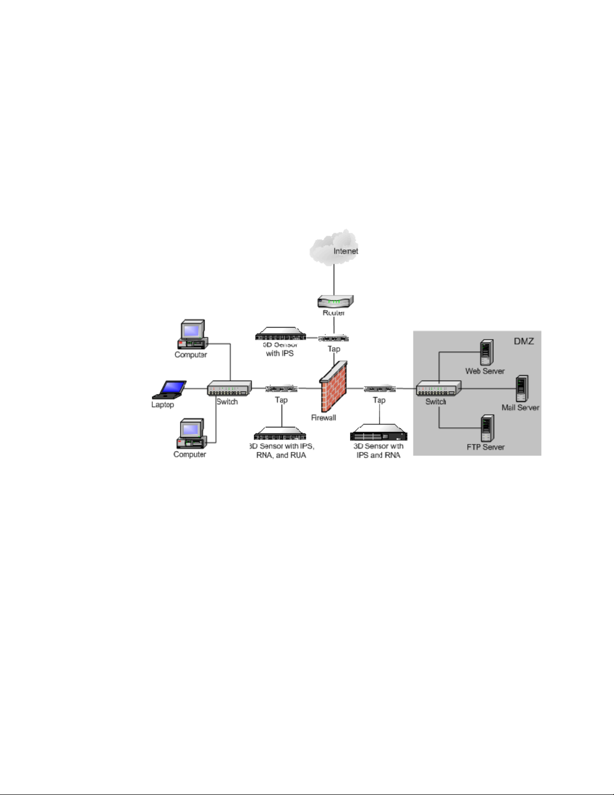
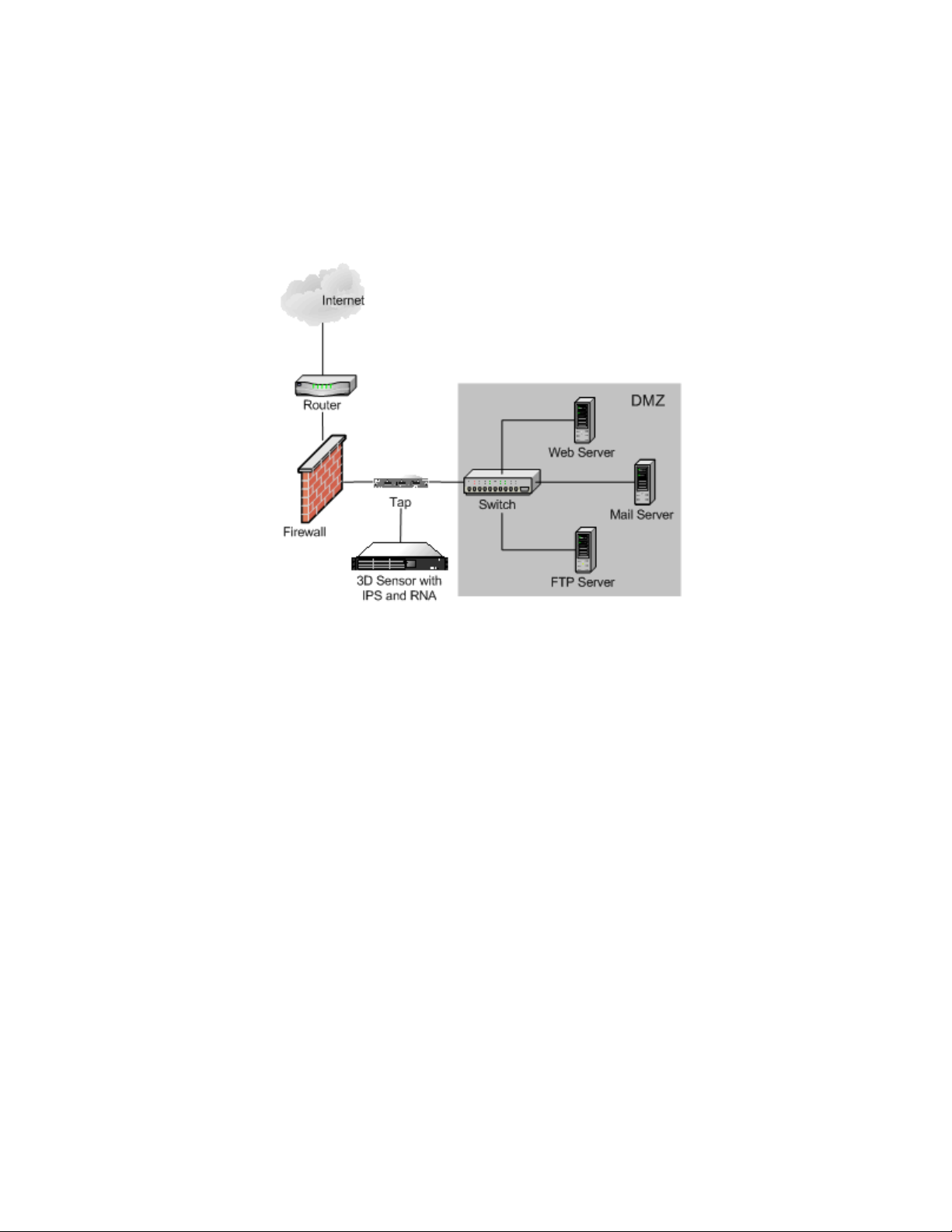
In the following simple network architecture diagram, the network has three
areas with three different security policies:
• between the border router and the firewall
• in the demilitarized zone, or DMZ
• in the internal, protected network
Chapter 1
Deploying your 3D Sensors in each of these locations serves different purposes.
Security requirements vary, so the following are typical location
recommendations:
• Placement outside the firewall gives you a clear picture of all the traffic
traversing your network via this gateway. This location is appropriate for IPS
only. Most enterprises would not need to identify user identities or employ
host and vulnerability detection capabilities in this area.
• Placement in the DMZ provides you with useful information about attacks
on outward-facing servers. This location is appropriate for IPS and RNA,
although some enterprises would want to add the user identification
capabilities of RUA here as well.
• Placement on the internal network monitors inbound traffic for firewall
misconfiguration and detects attacks that originate from hosts on the
internal network. All internal networks are ideal locations for the combined
capabilities of IPS, RNA, and RUA.
These three locations indicate where you may want to connect the 3D Sensor’s
sensing interfaces. Regardless of where you connect the sensing interfaces,
Version 4.10.3 Sourcefire 3D Sensor Installation Guide 11
Before You Begin
Typical 3D Sensor Deployments
make sure you connect the 3D Sensor’s management interface to a secure
internal network that is protected from unauthorized access.
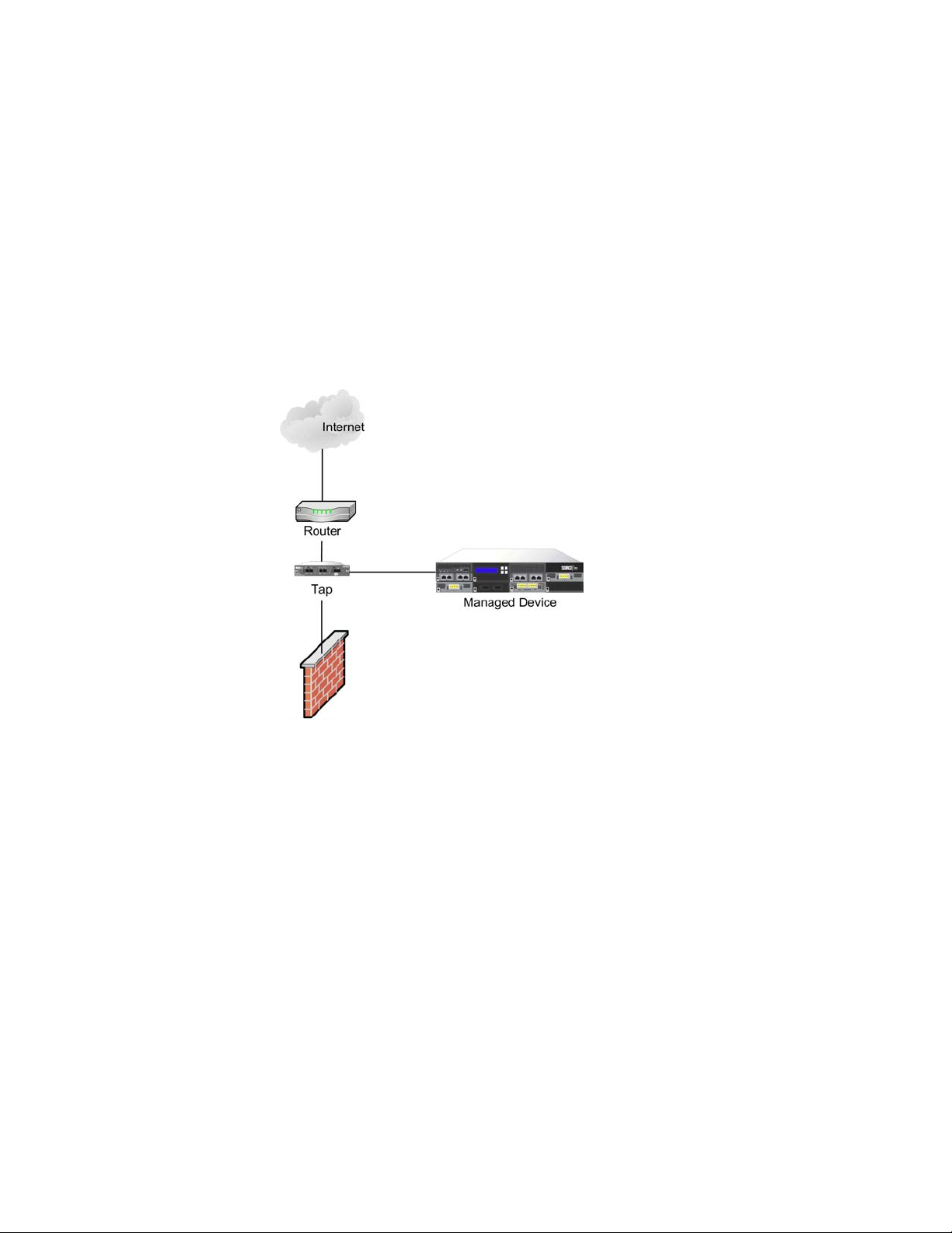
Outside the Firewall
Outside the firewall, the router provides the first line of defense. Although you
can configure most routers to block unwanted packets, this is not typically used
to secure the network segment between the router and the firewall. Placing the
3D Sensor here can help you detect attacks made against your network as well as
attacks from your network to another.
Chapter 1
Deploying the 3D Sensor on this segment of your network for a week or two can
help you understand what kinds of attacks reach your firewall and where they
originate. Although you can readily inspect all traffic traversing your network,
considerable resources are required to prioritize, investigate, and respond to
events that may be blocked by your firewall. Your enterprise’s ability to gain
knowledge from this approach depends on the amount of traffic traversing your
network and your security analyst resources. Gaining this kind of information can
help you tune your firewall rules to be as effective as possible.
Version 4.10.3 Sourcefire 3D Sensor Installation Guide 12
Before You Begin
Typical 3D Sensor Deployments
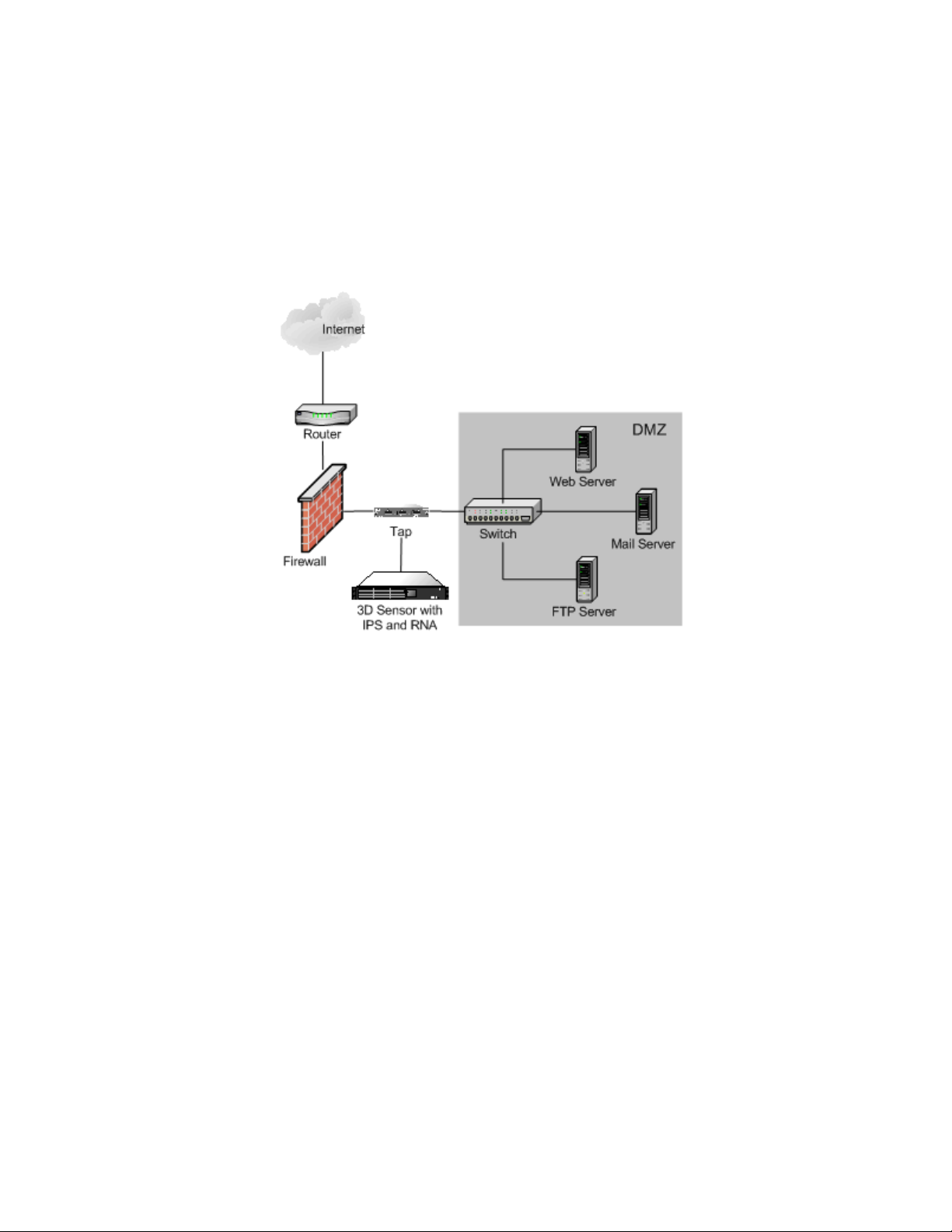
In the DMZ
In this simple network architecture, the DMZ contains outward-facing servers
(web, FTP, DNS, mail, and so on). The hosts in the DMZ provide services to
external users and are at a greater security risk than those inside the firewall.
Chapter 1
In this network configuration, the servers in the DMZ also provide services such
as mail relay and web proxy to users on the internal network. A 3D Sensor with
IPS on this segment can provide useful information about the kinds of attacks on
outward facing servers as well as detect attacks directed to the Internet that
originate from a compromised server in the DMZ. Adding RNA to the sensor on
this segment can help you monitor these exposed servers for changes (for
example, a new unknown service suddenly appearing) that could indicate a
compromised server in the DMZ.
Version 4.10.3 Sourcefire 3D Sensor Installation Guide 13

Before You Begin
Typical 3D Sensor Deployments
On the Internal Side of Redundant Firewalls
Many network environments implement a redundant data path for Internet
connectivity. These secondary links may also require monitoring in situations
when the primary, or active, links go offline. Two options are available for ensuring
continuous monitoring during a primary link outage:
• A single 3D Sensor can monitor both the active (primary) and passive
(secondary) links over multiple inline links passing through the single
sensor. Built-in fail-open bypass capabilities ensure that traffic is always
moving through the appliance, and any traffic that moves to the secondary
link is still monitored by the sensor appliance as if nothing had failed.
• Two 3D Sensor appliances may be placed on the network. One can monitor
the active (primary) link and one the passive (secondary) link, with both
sensors up and continuously monitoring the specified link. If a condition
causes traffic to move from the primary to the secondary link, the
3D Sensor on the secondary link automatically takes over all monitoring
responsibilities.
Chapter 1
On the Internal Network
Although the sample network includes a firewall configured to provide security to
the servers and workstations on the internal network, 3D Sensors on this
segment can monitor traffic that is allowed inbound by the firewall by choice or
due to firewall misconfiguration. For example, if you have a security policy that
prohibits FTP connections to any host on the internal network, you can create a
rule on the 3D Sensor that will trigger when it detects traffic directed to port 21
on any IP address in the segment. A 3D Sensor on this segment can also detect
attacks that originate from hosts on the internal network. For instance, attaching
one 3D Sensor to a mirror or span port on a switch helps you identify attacks from
Version 4.10.3 Sourcefire 3D Sensor Installation Guide 14
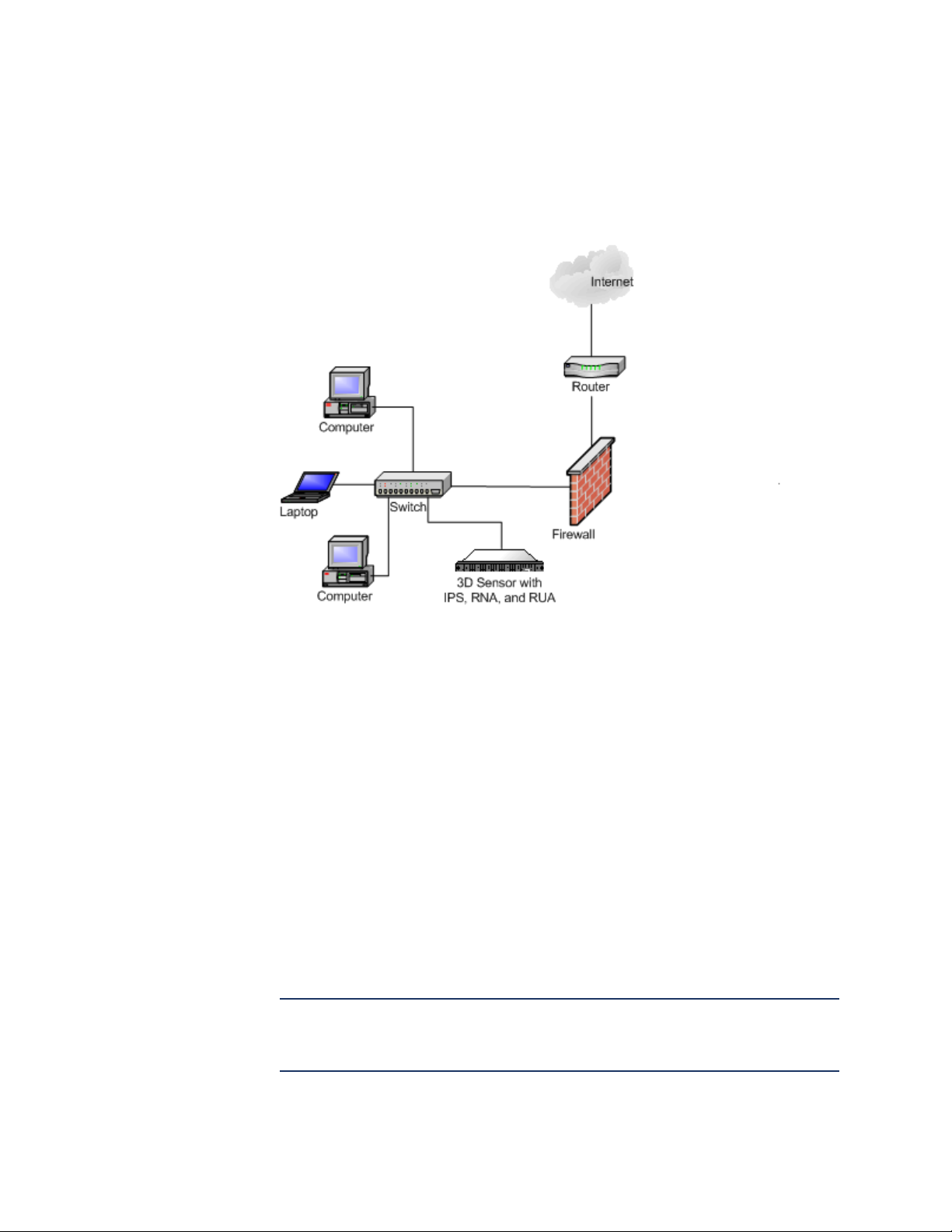
Before You Begin
Typical 3D Sensor Deployments
one computer on the internal network directed against other computers on the
internal network if the attack traffic traverses the switch.
Chapter 1
Similarly, if a host on your network is compromised from within, RNA can
immediately identify both unauthorized changes on hosts. For example, a
Microsoft shop can use RNA to identify in real time a rogue Linux or FreeBSD
system that mysteriously appears on their network segment. RNA on a switched
network segment can monitor all the hosts and services on the segment for
changes and vulnerabilities. For example, attaching an 3D Sensor to a mirror or
SPAN port on the switch allows you to monitor the entire network segment, as
long as all traffic to and from all hosts on the segment traverses the switch.
In either case, by adding RUA to the 3D Sensor, you can immediately identify the
user who is logged into the host that is running the rogue operating system or
launching the internal attack.
Deploying a Multi-Port 3D Sensor
Selected models of the 3D Sensor offer multiple sensing ports on an adapter
card. You can use the multi-port 3D Sensors in either of two ways:
• to recombine the separate connections from a network tap
• to capture and evaluate traffic from different networks
IMPORTANT! Although each port is capable of receiving the full throughput for
which the sensor is rated, the total traffic on the 3D Sensor cannot exceed its
bandwidth rating without some packet loss.
Version 4.10.3 Sourcefire 3D Sensor Installation Guide 15
Before You Begin
Typical 3D Sensor Deployments
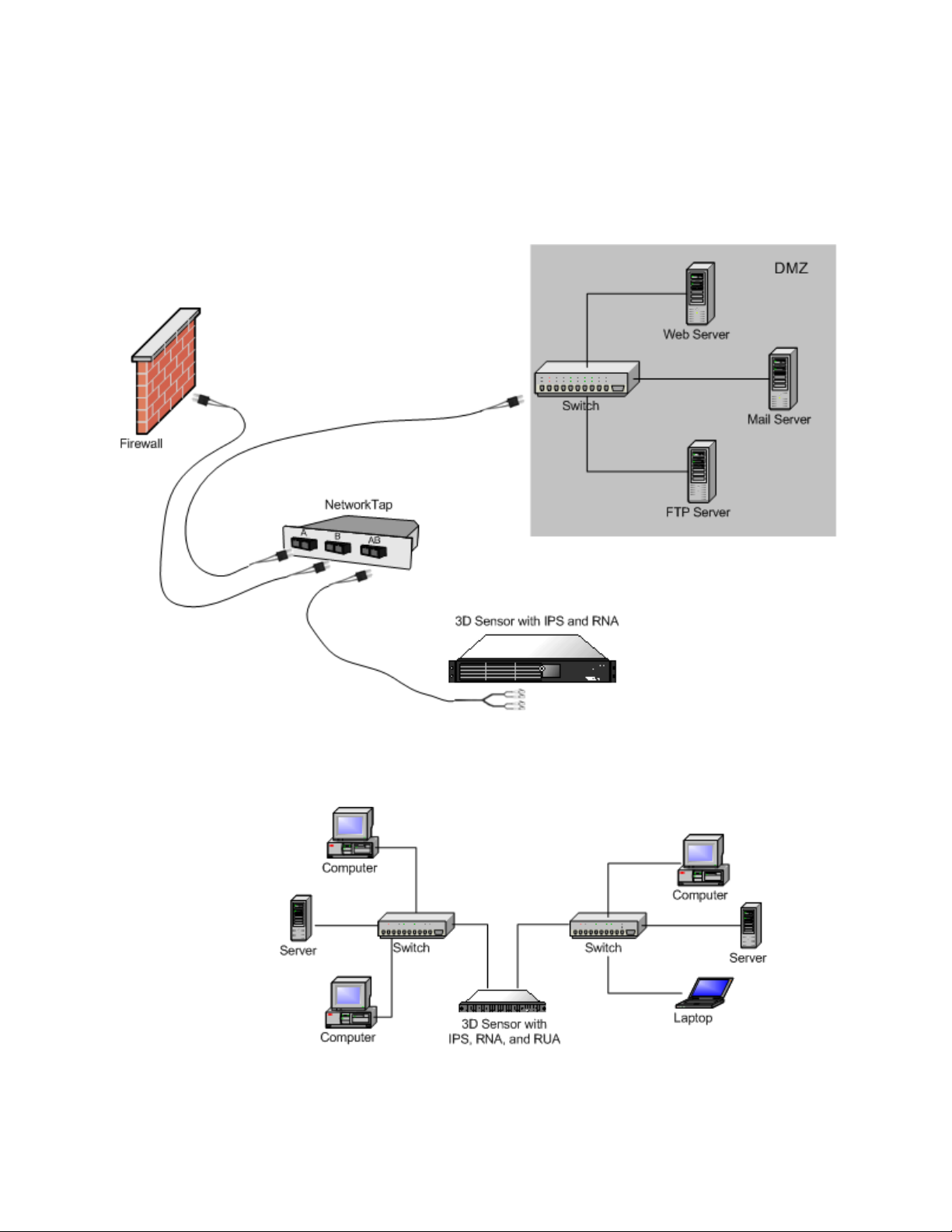
Deploying a multi-port 3D Sensor with a network tap is a straightforward process.
The following diagram shows a network tap installed on a high-traffic network
segment.
Chapter 1
In this scenario, the tap transmits incoming and outgoing traffic through separate
ports. When you connect the multi-port adapter card on the 3D Sensor to the tap,
the 3D Sensor is able to combine the traffic into a single data stream so that it
can be analyzed.
Version 4.10.3 Sourcefire 3D Sensor Installation Guide 16
Before You Begin
Typical 3D Sensor Deployments
Note that with a gigabit optical tap, as shown in the illustration below, both sets
of ports on the 3D Sensor are used by the connectors from the tap.
Chapter 1
If your 3D Sensor supports multiple detection engines, you can also create
interface sets to capture data from separate networks. The following diagram
shows a single sensor with a dual-port adapter and two interface sets connected
to two networks.
Version 4.10.3 Sourcefire 3D Sensor Installation Guide 17
Before You Begin
Other Deployment Options
Other Deployment Options
The following sections describe other installation scenarios that may affect your
enterprise’s deployment of the Sourcefire 3D System:
• Integrating with VPNs on page 18
• Detecting Intrusions on Other Points of Entry on page 18
• Deploying in Multi-Site Environments on page 20
• Integrating 3D Sensors with RNA within Complex Networks on page 21
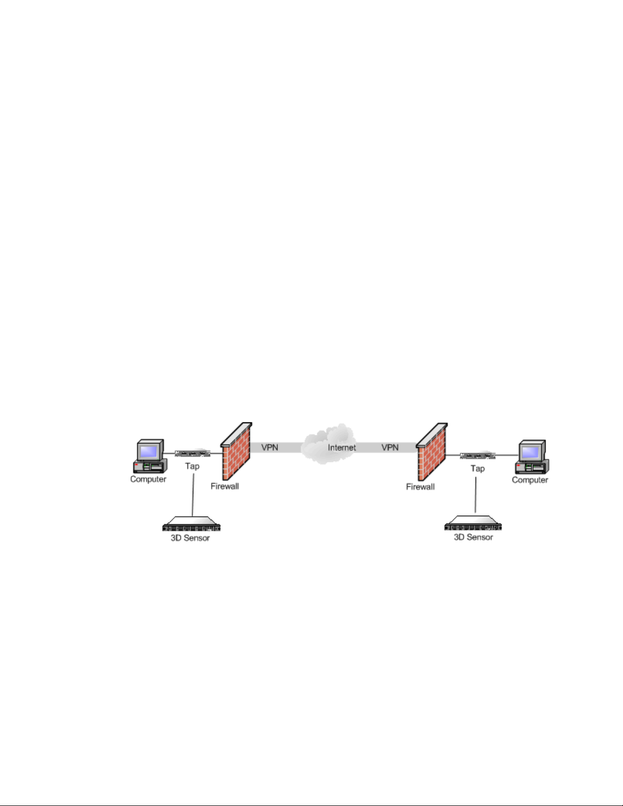
Integrating with VPNs
Virtual private networks, or VPNs, use IP tunneling techniques to provide the
security of a local network to remote users over the Internet. In general, VPN
solutions encrypt the data payload in an IP packet. The IP header is unencrypted
so that the packet can be transmitted over public networks in much the same way
as any other packet. When the packet arrives at its destination network, the
payload is decrypted and the packet is directed to the proper host.
Because network appliances cannot analyze the encrypted payload of a VPN
packet, placing 3D Sensors outside the terminating endpoints of the VPN
connections ensures that all packet information can be accessed. The following
diagram illustrates how 3D Sensors can be deployed in a VPN environment.
Chapter 1
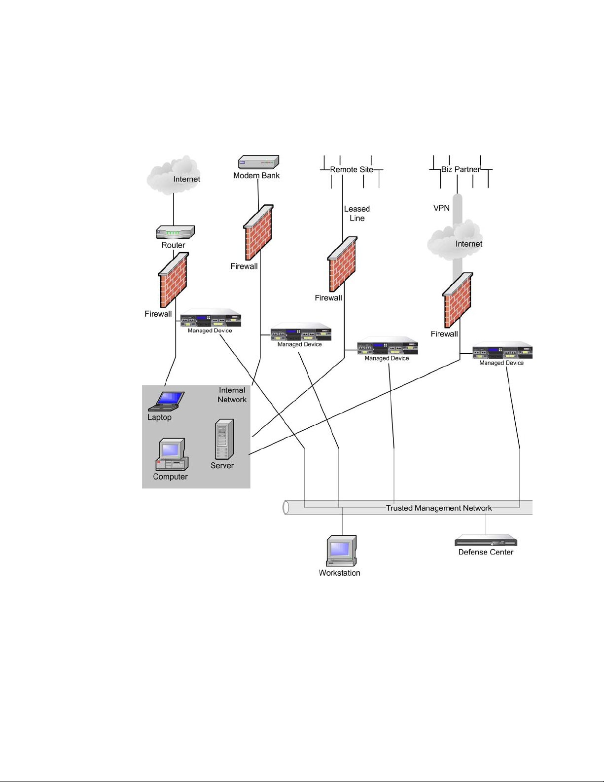
Detecting Intrusions on Other Points of Entry
Many networks include more than one access point. Instead of a single border
router that connects to the Internet, some enterprises use a combination of the
Internet, modem banks, and direct links to business partner networks. In general,
you should deploy 3D Sensors near firewalls (either inside the firewall, outside
the firewall, or both) and on network segments that are important to the integrity
and confidentiality of your business data. The following diagram shows how
Version 4.10.3 Sourcefire 3D Sensor Installation Guide 18
Before You Begin
Other Deployment Options
3D Sensors can be installed at key locations on a complex network with multiple
entry points.
Chapter 1
Version 4.10.3 Sourcefire 3D Sensor Installation Guide 19
Before You Begin
Other Deployment Options
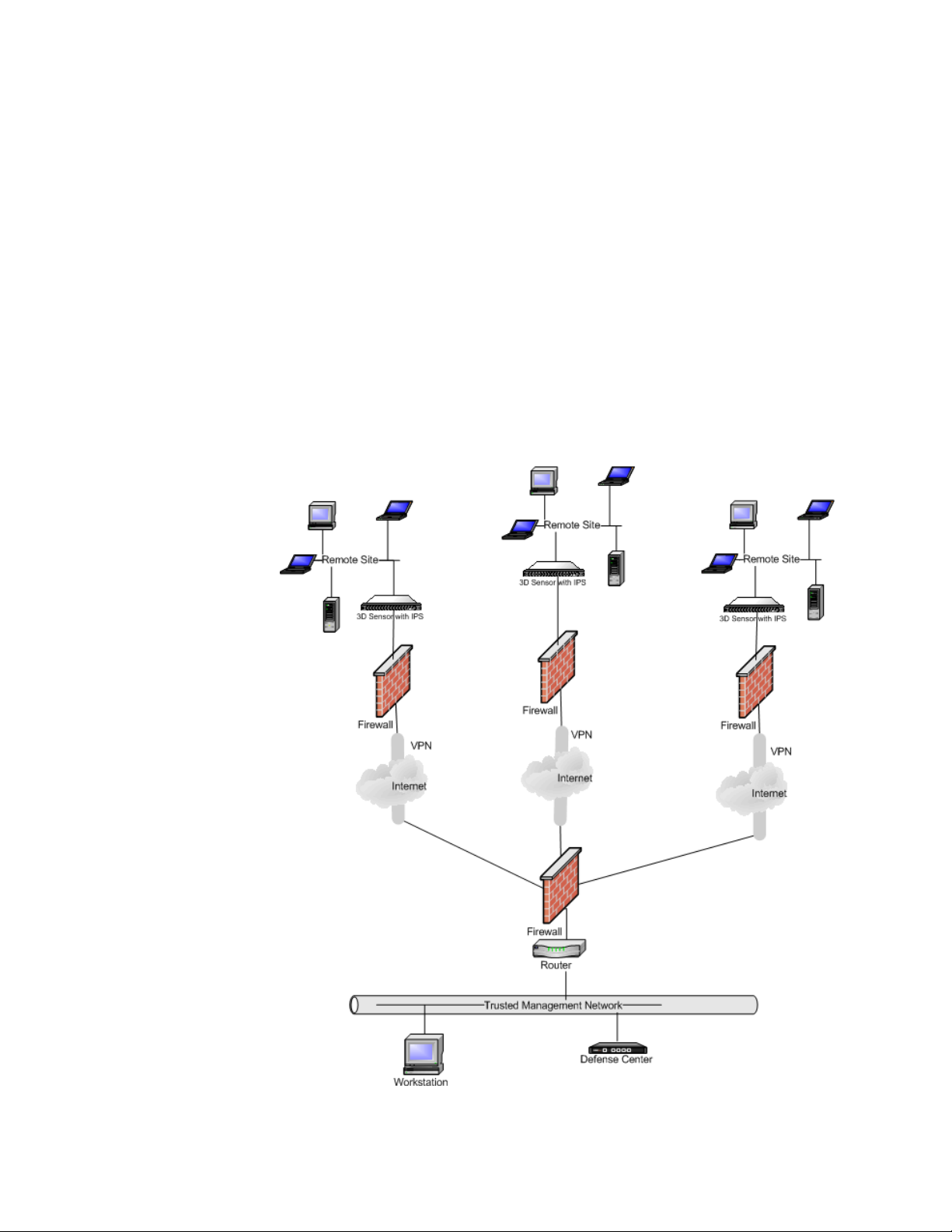
Deploying in Multi-Site Environments
Many organizations want to extend intrusion detection across a geographically
disparate enterprise and then analyze all the IPS data from one location. The
Sourcefire 3D System supports this by offering the Defense Center, which
aggregates and correlates events from 3D Sensors deployed throughout the
organization’s many locations. Unlike deploying multiple 3D Sensors and Defense
Centers in the same geographic location on the same network, when deploying
3D Sensors in disparate geographic locations, you must take precautions to
ensure the security of the 3D Sensors and the data stream. To secure the data,
you must isolate the 3D Sensors and Defense Center from unprotected
networks. You can do this by transmitting the data stream from the 3D Sensors
over a VPN or with some other secure tunneling protocol as shown in the
following diagram.
Chapter 1
Version 4.10.3 Sourcefire 3D Sensor Installation Guide 20

Before You Begin
Other Deployment Options
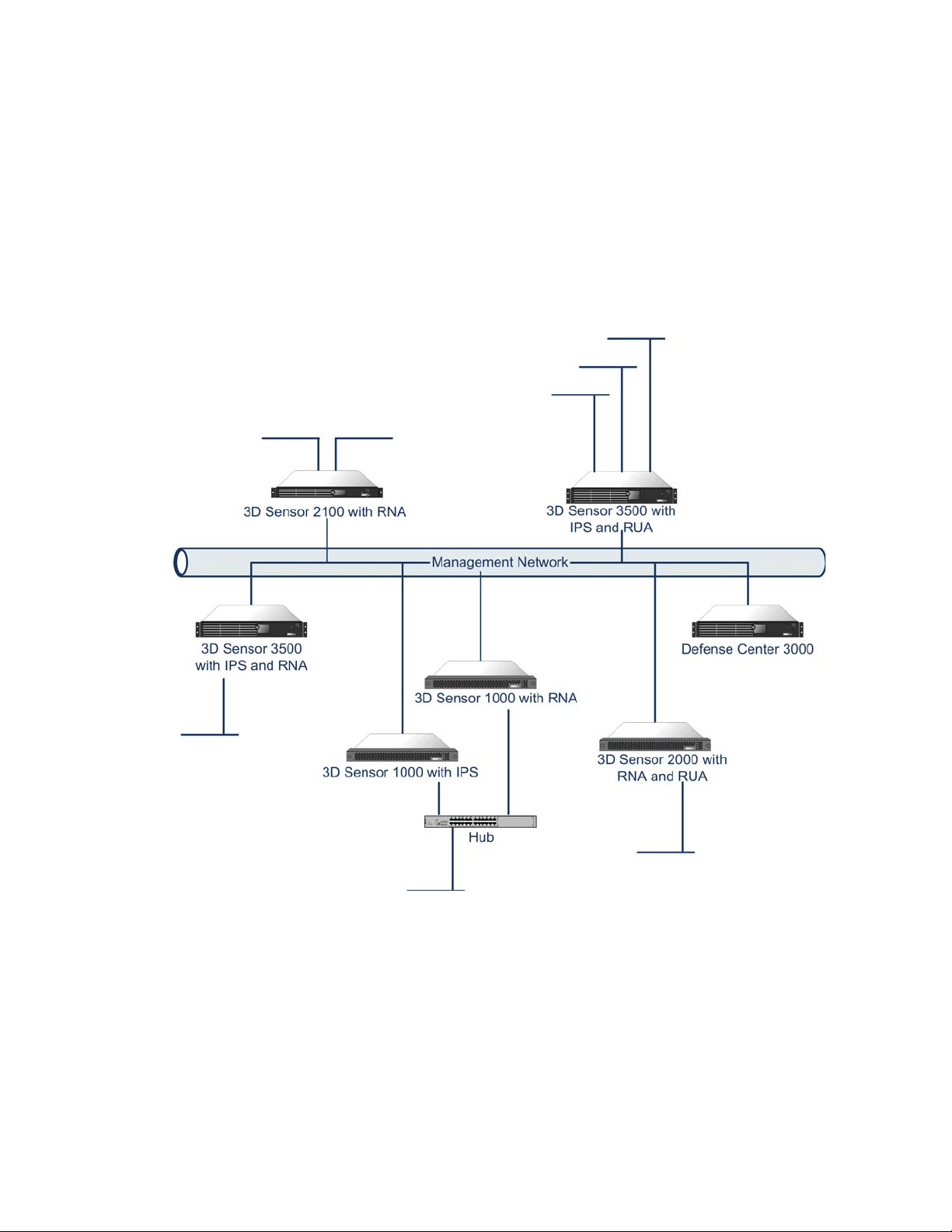
Integrating 3D Sensors with RNA within Complex Networks
You can deploy 3D Sensors with RNA in more complex network topologies than a
simple multi-sector network. This section describes the issues surrounding
network discovery and vulnerability analysis when deploying RNA in
environments where proxy servers, NAT devices, and VPNs exist, in addition to
information about using the Sourcefire Defense Center to manage multiple
3D Sensors and the deployment and management of 3D Sensors in a multi-site
environment.
Integrating with Proxy Servers and NAT
Network address translation (NAT) devices or software may be employed across a
firewall, effectively hiding the IP addresses of internal hosts behind a firewall. If
3D Sensors with RNA are placed between these devices or software and the
hosts being monitored, RNA may incorrectly identify the hosts behind the proxy
or NAT device. In this case, Sourcefire recommends that you position 3D Sensors
with RNA inside the network segment protected by the proxy or NAT device to
ensure that hosts are correctly detected.
Chapter 1
Integrating with Load Balancing Methods
In some network environments, “server farm” configurations are used to
perform network load balancing for services such as web hosting, FTP storage
sites, and so on. In load balancing environments, IP addresses are shared
between two or more hosts with unique operating systems. In this case, RNA
detects the operating system changes and cannot deliver a static operating
system identification with a high confidence value. Depending on the number of
different operating systems on the affected hosts, RNA may generate a large
number of operating system change events or present a static operating system
identification with a lower confidence value.
Other RNA Detection Considerations
If an alteration has been made to the TCP/IP stack of the host being identified,
RNA may not be able to accurately identify the host operating system. In some
cases, this is done to improve performance. For instance, administrators of
Windows hosts running the Internet Information Services (IIS) Web Server are
encouraged to increase the TCP window size to allow larger amounts of data to
be received, thereby improving performance. In other instances, TCP/IP stack
alteration may be used to obfuscate the true operating system to preclude
accurate identification and avoid targeted attacks. The likely scenario that this
intends to address is where an attacker conducts a reconnaissance scan of a
network to identify hosts with a given operating system followed by a targeted
attack of those hosts with an exploit specific to that operating system.
Version 4.10.3 Sourcefire 3D Sensor Installation Guide 21

Before You Begin
Understanding Detection Engines and Interface Sets
Understanding Detection Engines and Interface Sets
A detection engine is the mechanism on a 3D Sensor that is responsible for
analyzing the traffic on the network segment where the sensor is connected.
Depending on which components are licensed on the sensor, 3D Sensors can
support three types of detection engines: IPS, RNA, and RUA.
A detection engine has two main components:
• an interface set, which can include one or more sensing interfaces
• a detection resource, which is a portion of the sensor’s computing
resources
3D Sensor models have at least three detection resources available and can
support at least three detection engines: one for IPS, one for RNA, and the third
for RUA.
An interface set refers to a grouping of one or more sensing interfaces on a
sensor; a sensing interface can belong to only one interface set at a time. The
Sourcefire 3D System supports three types of interface sets, but the interface
options available to you depend on the type of sensor and the capabilities of its
sensing interfaces.
Chapter 1
Interface Set Types
Type Description
Passive Use a passive interface set if you deployed the sensor out of
band from the flow of network traffic.
Inline Use an inline interface set if you deployed the sensor inline on
your network and the sensing interfaces do not support
automatic fail-open capabilities. Note that you can use any
two of the non-fail-open interfaces on the sensor’s network
interface cards as part of an inline interface set.
Inline with
Fail Open
The typical scenario for deploying 3D Sensors across your network infrastructure
calls for installing a different sensor in each location where you want to enforce a
security policy. In other words, you may want to install one 3D Sensor in the DMZ
and others on each internal network segment. If you have a network segment
with hosts that are likely to be targets of specialized attacks (for example, a web
host farm), you would deploy another 3D Sensor there.
Use an inline with fail-open interface set if you deployed the
sensor inline on your network and the sensing interfaces do
support automatic fail-open capabilities. Note that you must
use paired fail-open interfaces on the sensor’s network
interface cards for an inline with fail-open interface set.
Multiple IPS detection engines on a single 3D Sensor can provide you with more
flexibility in deploying 3D Sensors throughout your network. A detection engine is
Version 4.10.3 Sourcefire 3D Sensor Installation Guide 22

Before You Begin
Understanding Detection Engines and Interface Sets
like a virtual sensor within a sensor. When you create a detection engine on a
3D Sensor, you specify which of the sensor’s sensing interfaces it uses and what
portion of the sensor’s detection resources it can use. You can then create and
apply an intrusion policy that is tuned especially for the network attacks that are
likely to be seen on the segment of the network that the detection engine
monitors. See the “Using Detection Engines and Interface Sets” chapter in the
Sourcefire 3D System User Guide for more information about creating and using
detection engines.
Understanding Detection Resources and 3D Sensor Models
3D Sensor with IPS can use multiple detection resources per detection engine,
which allows you to use more computing resources when network traffic is high.
For example, if you plan to use the 3D3500 sensor in inline mode, you could
assign two detection resources to your detection engine to allow processing of
more events per second. As a best practice, use one detection resource per
application per core on your appliance. Different sensor models have different
numbers of detection resources as shown in the Detection Resources by Model
table on page 23:
Chapter 1
• The Optimal column indicates the per sensor total number of detection
resources you should use if you want to maximize the performance of the
sensor. It also indicates the maximum number of detection resources you
can assign a single detection engine.
• The Maximum column indicates the total number of detection resources
available on the sensor.
• The Combination Restrictions column indicates the permitted combinations of
detection resources that you can allocate to detection engines on the same
sensor; 3D Sensors can run combinations of IPS, RNA, and RUA.
Note that for some sensor models, the availability of detection resources
depends on the amount of RAM on the sensor, which you can determine using
the Memory Usage field on the Statistics page (Operations > Monitoring > Statistics).
Detection Resources by Model
Model Optimal
per Sensor
3D500 1 2 Maximum of one IPS
3D1000 (512MB RAM) 1 2 Maximum of one IPS
Maximum
per Sensor
Combination
Restrictions
and either one RNA or
one RUA
and either one RNA or
one RUA
3D1000 (1GB RAM) 1 2 No restrictions
Version 4.10.3 Sourcefire 3D Sensor Installation Guide 23

Before You Begin
Understanding Detection Engines and Interface Sets
Detection Resources by Model (Continued)
Chapter 1
Model Optimal
per Sensor
3D2000 1 2 No restrictions
3D2100 2 3 No restrictions
3D2500 2 4 No restrictions
3D3000 2 4 No restrictions
3D3500 2 6 No restrictions
3D4500 4 8 No restrictions
3D6500 8 12 No restrictions
3D7010 Auto 6 No restrictions
3D7020 Auto 6 No restrictions
3D7030 Auto 6 No restrictions
3D7110 Auto 6 No restrictions
Maximum
per Sensor
Combination
Restrictions
3D7120 Auto 6 No restrictions
3D8120 Auto 16 No restrictions
3D8130 Auto 22 No restrictions
3D8140 Auto 22 No restrictions
3D8250 Auto 22 No restrictions
3D9900 7 12 No restrictions
Note that disabling hyperthreading on 3D7010/7020/7030 and 8000 Series
sensors reduces the maximum number of detection engines you can create. If
you disable hyperthreading after creating more than the allowable number of
detection engines for a sensor with disabled hyperthreading, you are prohibited
from creating additional detection engines. For information on hyperthreading,
see “Command Line Reference” in the Sourcefire 3D System User Guide.
Version 4.10.3 Sourcefire 3D Sensor Installation Guide 24

Before You Begin
Connecting Sensors to Your Network
Comparing Inline and Passive Interface Sets
An interface set is comprised of one or more sensing interfaces on the
3D Sensor. Each detection engine is assigned to an interface set and uses those
interfaces to monitor the traffic on specific network segments. Interface sets can
be one of the following types:
• passive
• inline
• inline with fail open
If you create an IPS detection engine that uses either type of the inline interface
set, you can deploy your detection engine inline. This allows you to take
advantage of drop rules that prevent suspicious traffic from reaching a potentially
vulnerable host. You can also use replace rules that substitute malicious content
with a benign alternative. You can also create RNA and RUA detection engines for
inline or inline with fail open interface sets.
A detection engine that uses an inline with fail open interface set has the same
properties as an inline interface set with one exception. You can only use an inline
with fail open interface set with fail-open network interface cards (NICs). If a
3D Sensor with a fail-open card should fail for some reason (power failure, hard
drive failure, and so on), traffic is not blocked by the sensor and your network
continues to function.
On the 3D9900 model of the 3D Sensor, you can also take advantage of a feature
called tap mode. Tap mode allows you to use interface sets to passively monitor
traffic when your sensor is deployed inline on your network.
Chapter 1
Connecting Sensors to Your Network
There are several ways to connect 3D Sensors to your network. The following
sections outline the supported connection methods:
• Using a Hub on page 26
• Using a Span Port on page 26
• Using a Network Tap on page 26
Additionally, Issues for Copper Cabling in Inline Deployments on page 27 explains
some of the guidelines for using straight-through or crossover cables in your
deployment and Special Case: Connecting 8000 Series Devices on page 29
describes how to configure stable network links for Series 3 devices.
Version 4.10.3 Sourcefire 3D Sensor Installation Guide 25

Before You Begin
Connecting Sensors to Your Network
Using a Hub
An Ethernet hub is an inexpensive way to ensure that the detection engine on a
3D Sensor can see all the traffic on a network segment. Most hubs of this type
take the IP traffic meant for any of the hosts on the segment and broadcast it to
all the devices connected to the hub. Connect the interface set to the hub to
monitor all incoming and outgoing traffic on the segment. Using a hub does not
guarantee that the detection engine sees every packet on a higher volume
network because of the potential of packet collision. For a simple network with
low traffic, this is not likely to be a problem. In a high-traffic network, a different
option may provide better results. Note that if the hub fails or loses power, the
network connection is broken. In a simple network, the network would be down.
IMPORTANT! Some devices are marketed as hubs but actually function as
switches and do not broadcast each packet to every port. If you attach your
3D Sensor to a hub, but do not see all the traffic, you may need to purchase a
different hub or use a switch with a Span port.
Chapter 1
Using a Span Port
Many network switches include a span port that mirrors traffic from one or more
ports. By connecting an interface set to the span port, you can monitor the
combined traffic from all ports, generally both incoming and outgoing. If you
already have a switch that includes this feature on your network, in the proper
location, then you can deploy the detection on multiple segments with little extra
equipment cost beyond the cost of the 3D Sensor. In high-traffic networks, this
solution has its limitations. If the span port can handle 200 Mbps and each of
three mirrored ports can handle up to 100 Mbps, then the span port is likely to
become oversubscribed and drop packets, lowering the effectiveness of the
3D Sensor.
Using a Network Tap
Network taps allow you to passively monitor traffic without interrupting the
network flow or changing the network topology. Taps are readily available for
different bandwidths and allow you to analyze both incoming and outgoing
packets on a network segment. Unfortunately, you can monitor only a single
network segment with most taps, so they are not a good solution if you want to
monitor, for example, the traffic on two out of the eight ports on a switch.
Instead, you would have to install the tap between the router and the switch and
access the full IP stream to the switch.
By design, network taps divide incoming and outgoing traffic into two different
streams over two different cables. 3D Sensors offer multi-port options that
recombine the two sides of the conversation so that the entire traffic stream is
evaluated by the decoders, the preprocessors, and the detection engine.
Version 4.10.3 Sourcefire 3D Sensor Installation Guide 26

Before You Begin
Connecting Sensors to Your Network
Issues for Copper Cabling in Inline Deployments
If you are deploying your sensor inline on your network, and you are taking
advantage of your sensor’s fail open capabilities to maintain network connectivity
even if the sensor goes down, there are a few important points to keep in mind.
If you are deploying a sensor with fiber fail-open interfaces, there are no special
cabling issues beyond ensuring that the connections are securely fastened and
the cables are not kinked. However, if you are deploying sensors with copper
rather than fiber network interfaces, then you must be aware of the sensor model
that you are using, because different sensor models use different network cards.
The network interface cards (NICs) in the sensor support a feature called
Auto-Medium Dependent Interface Crossover (Auto-MDI-X), which allows
network interfaces to configure automatically whether you are using a
straight-through or crossover Ethernet cable to connect to another network
device. However, the network cards in the sensor can act in a different manner
when the sensor loses power and the NICs fail open. Some of the cards will fail
open as a straight-through connection, others as crossover. This has implications
for you as you choose cables to connect a sensor to each endpoint. The Sensor
Models and Fail Open Characteristics table lists the various sensor models and
whether they fail open as crossover or straight-through devices.
Chapter 1
Sensor Models and Fail Open Characteristics
Model Fails open as...
3D500 straight-through
3D1000 straight-through
3D2000 straight-through
3D2100 straight-through
3D2500 straight-through
3D3500 straight-through
3D4500 straight-through
3D6500 crossover
3D9900 crossover
7000 Series crossover
8000 Series crossover
Version 4.10.3 Sourcefire 3D Sensor Installation Guide 27

Before You Begin
Connecting Sensors to Your Network
For sensor models that fail open as straight-through, wire the device as you
would for normal operation without a sensor deployed. The link should work with
power to the sensor removed. In most cases you should use one crossover cable
and one straight-through cable to connect the sensor to the two endpoints.
For sensor models that fail open as crossover, wire the device as would normally
be done with the 3D Sensor live on the network. In most cases you should use
two straight-through cables to connect the sensor to the two endpoints.
Chapter 1
The following table indicates where you should use crossover or straight-through
cables in your hardware bypass configurations.
Valid Configurations for Hardware Bypass
Endpoint 1 Cable Sensor Cable Endpoint 2
MDIX===MDI
MDIX==MDI
MDI = = X MDI
MDI===MDIX
MDIX=X=MDIX
MDI = X = MDI
MDIXXXMDI
MDIX X X = MDI
= indicates a straight-through cable or sensor bypass connection
X indicates a crossover cable or sensor bypass connection
Version 4.10.3 Sourcefire 3D Sensor Installation Guide 28

Before You Begin
Using a Sourcefire Defense Center
Note that every network environment is likely to be unique, with endpoints that
have different combinations of support for Auto-MDI-X. The easiest way to
confirm that you are installing your sensor with the correct cabling is to begin by
connecting the sensor to its two endpoints using one of the cabling scenarios
shown in the illustration, but with the sensor powered down. Ensure that the two
endpoints can communicate. If they cannot communicate, then one of the cables
is the incorrect type. Switch one (and only one) of the cables to the other type,
either straight-through or crossover.
After the two endpoints can successfully communicate with the inline sensor
powered down, power up the sensor. The Auto-MDI-X feature ensures that the
two endpoints will continue to communicate. Note that if you have to replace an
inline sensor, you should repeat the process of ensuring that the endpoints can
communicate with the new sensor powered down to protect against the case
where the original sensor and its replacement have different fail-open
characteristics.
The Auto-MDI-X setting functions correctly only if you allow the network
interfaces to auto-negotiate. If your network environment requires that you turn
off the Auto Negotiate option on the Network Interface page, then you must
specify the correct MDI/MDIX option for your inline network interfaces. See
“Editing Network Interface Configurations” in the Sourcefire 3D System User
Guide for more information.
Chapter 1
Special Case: Connecting 8000 Series Devices
8000 Series managed devices do not support half duplex network links; they also
do not support differences in speed or duplex configurations at opposite ends of a
connection. To ensure a stable network link, you must either auto-negotiate on
both sides of the connection, or set both sides to the same static speed.
Using a Sourcefire Defense Center
You must manage 7000 Series and 8000 Series 3D Sensors with a Sourcefire
Defense Center. The Defense Center aggregates and correlates events
generated by multiple 3D Sensors on different segments of your network. You
can also use the Defense Center to manage, change, and standardize the
intrusion policies on 3D Sensors.
In addition to running Series 2 3D Sensors with IPS as standalone appliances, you
can manage 3D Sensors with the Sourcefire Defense Center. The Defense
Center aggregates and correlates events generated by multiple 3D Sensors on
different segments of your network. You can also use the Defense Center to
manage, change, and standardize the intrusion policies on 3D Sensors.
To safeguard the Defense Center, it must be installed on a protected internal
network. Although the Defense Center is configured to have only the necessary
services and ports available, you must make sure that attacks cannot reach it from
outside the firewall.
Version 4.10.3 Sourcefire 3D Sensor Installation Guide 29
Before You Begin
Using a Sourcefire Defense Center
If the 3D Sensor and the Defense Center reside on the same network, you can
connect the management interface on the 3D Sensor to the same protected
internal network as the Defense Center. This allows you to securely control the
sensor from the Defense Center and aggregate the event data generated on the
3D Sensor’s network segment. By using the Defense Center’s filtering
capabilities, you can analyze and correlate data from attacks across your network
to evaluate how well your security policies are being implemented.
Chapter 1
Version 4.10.3 Sourcefire 3D Sensor Installation Guide 30

Before You Begin
Communication Ports
Chapter 1
Communication Ports
The Sourcefire 3D System uses ports 443 and 8305 to communicate internally
and externally between the Defense Center and sensors. Open other ports to
enable optional functionality within your deployment.
Communication Ports
Ports Description Protocol Direction Open the port to...
22 ssh/ssl TCP Bidirectional allow a secure remote connection to the
appliance. SSH version 2 is supported
for command-line connections; TLS
version 1 and SSL version 3 are
supported for HTTPS connections.
25 smtp TCP Outbound send email notices and alerts from the
appliance.
53 dns TCP Outbound use DNS.
67, 68 dhcp UDP Outbound use DHCP. Default is disabled.
80 http TCP Outbound allow the RSS Feed dashboard widget to
162 snmp UDP Bidirectional provide access if you enabled SNMP
389, 636 ldap TCP Outbound use RUA and for authentication.
443 https TCP Inbound
Bidirectional
514 syslog UDP Outbound use for remote syslog server.
623 SOL/LOM UDP Bidirectional allow a Serial Over LAN connection to
1500, 2000 database access TCP Inbound access the Defense Center or Master
connect to a remote web server; use for
auto-update.
polling (inbound) and SNMP traps
(outbound).
access the appliance. Required.
Add outbound access to allow
appliances to download software
updates.
use Lights Out Management.
Defense Center if external database
access is enabled.
Version 4.10.3 Sourcefire 3D Sensor Installation Guide 31

Before You Begin
Communication Ports
Communication Ports (Continued)
Ports Description Protocol Direction Open the port to...
Chapter 1
1812, 1813 RADIUS UDP Outbound use RADIUS. Open both ports to ensure
3306 RUA Agent TCP Inbound allow communication between the
8301 Intrusion Agent TCP Bidirectional allow communication between the
8302 eStreamer TCP Bidirectional use for an eStreamer client.
8305 sensor
management
8307 Host Input
Client API
18183 OPSEC SAM TCP Outbound use OPSEC for remediations.
TCP Bidirectional communicate between the Defense
TCP Bidirectional communicate with the Defense Center
that RADIUS functions correctly.
Ports 1812 and 1813 are the default, but
you can configure RADIUS to user other
ports instead. For more information, see
the Sourcefire 3D System User Guide.
Defense Center and RUA Agents.
Defense Center and Intrusion Agents.
Center and 3D Sensors. Required.
during client/server authentication.
Version 4.10.3 Sourcefire 3D Sensor Installation Guide 32

Chapter 2
Installing a 3D Sensor
Depending on what you have licensed and which sensor model you are using, the
Sourcefire 3D Sensor can host the RNA component, the IPS component, the
RUA component, or any combination of the three. The IPS component requires
that you install a license on the sensor itself during the initial setup process. The
RNA and RUA components require that you manage the sensor with a Defense
Center and that you install an RNA host or RUA user license on the Defense
Center.
TIP! You can also install an RUA Agent on a Microsoft Active Directory server to
take advantage of RUA features. The RUA Agent installation process is explained
in the Sourcefire 3D System User Guide.
You can install the 3D Sensor as part of a larger Sourcefire 3D System
deployment or, if you are licensing the IPS component, as a standalone network
monitoring appliance. You can also manage multiple 3D Sensors using the
Defense Center, which allows for data correlation and display for IPS, RUA, and
RNA.
See the following sections for more information about installing a 3D Sensor:
• Included Items on page 34
• Security Considerations on page 34
• Identifying the Management and Sensing Interfaces on page 35
• Installing the 3D Sensor in a Rack on page 62
• Configuring the Management Interface on page 64
• Performing the Initial Setup on page 72
Version 4.10.3 Sourcefire 3D Sensor Installation Guide 33

Installing a 3D Sensor
Included Items
Included Items
Chapter 2
• Redirecting Console Output on page 75
• Testing an Inline Fail-Open Interface Installation on page 76
• Checking for Updates on page 78
The following is a list of components that ship with Sourcefire appliances. As you
unpack the system and the associated accessories, check that your package
contents are complete as follows:
• one Sourcefire 3D Sensor
• power cord (two power cords are included with appliances that include
redundant power supplies)
• two Category 5e Ethernet straight-through cables
• one rack-mounting kit (not applicable to the 3D500; available separately for
the 3D7010/7020/7030)
IMPORTANT! Remove all factory packaging from delivered appliances and cables
before installation. Do not cover the vents or enclose the appliance; there must be
ample clearance on all sides of the chassis. Restricting the airflow may cause the
appliance to overheat.
Security Considerations
Sourcefire 3D System appliances are hardened to ensure secure operation. In
accordance with security best practices, before you install your appliance,
Sourcefire recommends that you consider the following:
• Locate your Sourcefire 3D System appliance in a lockable rack within a
secure location that prevents access by unauthorized personnel. If you are
installing a desktop model, make sure you place it within a secure location
that prevents access by unauthorized personnel.
• Allow only trained and qualified personnel to install, replace, administer, or
service the Sourcefire appliance.
• Always connect the management interface to a secure internal
management network that is protected from unauthorized access.
• Identify the specific workstation IP addresses that can be allowed to access
appliances. Restrict access to the appliance to only those specific hosts,
using the Access List within the appliance’s System Policy. For more
information, see the Sourcefire 3D System User Guide.
Version 4.10.3 Sourcefire 3D Sensor Installation Guide 34

Installing a 3D Sensor
Management Interface Sensing Interfaces
eth0 eth1 eth2 eth3 eth4
Identifying the Management and Sensing Interfaces
Identifying the Management and Sensing Interfaces
The Sourcefire 3D Sensor is delivered on different hardware appliances. Make
sure you refer to the correct illustration for your appliance as you follow the
installation procedure:
• Sourcefire 3D Sensor 500/1000/2000 on page 35
• Sourcefire 3D Sensor 2100/2500/3500/4500 on page 36
• Sourcefire 3D Sensor 6500 on page 38
• Sourcefire 3D Sensor 7010/7020/7030 on page 42
• Sourcefire 3D Sensor 7110/7120 on page 42
• Sourcefire 3D Sensor 8120/8130/8140 on page 45
• Sourcefire 3D Sensor 8250/8260/8270/8290 on page 48
• Sourcefire 3D Sensor 9900 on page 53
• Using 3D Sensors in a Stacked Configuration on page 55
Chapter 2
Sourcefire 3D Sensor 500/1000/2000
The 3D500, 3D1000, and 3D2000 models are Series 2 sensors, available on the
desktop appliance. The following illustration indicates the locations of the
management and sensing interfaces.
You can use the sensing interfaces to passively sense up to four separate
network segments.
You also can use paired interfaces in inline or inline with fail-open mode, which
allows you to deploy the 3D Sensor as an intrusion prevention system. The
3D500 can monitor one network when deployed inline, while the 3D1000 and
3D2000 can monitor two networks inline.
If you want to take advantage of the sensor’s automatic fail-open capability, you
must connect either the two interfaces on the left or the two interfaces on the
right to a network segment. This allows traffic to flow even if the sensor fails or
Version 4.10.3 Sourcefire 3D Sensor Installation Guide 35

Installing a 3D Sensor
paired
interfaces
paired
interfaces
(eth1 and eth2) (eth3 and eth4)
Management interface (eth0)
eth1 (Do not use)
Identifying the Management and Sensing Interfaces
loses power. You must also use the web interface to configure the interface set
as inline with fail open.
If you configure the interfaces as inline without using the fail-open capability, you
can use any two of the interfaces on the sensor as an inline pair.
IMPORTANT! By default, the initial setup process supports one inline fail-open
interface pair for
single interface sets by default: eth1:eth2, and eth3:eth4. For more information,
see “Using Detection Engines and Interface Sets” in the Sourcefire 3D System
User Guide.
eth1 and eth2. For the 3D1000 or 3D2000, the pairs are in
Chapter 2
Sourcefire 3D Sensor 2100/2500/3500/4500
The 3D2100, 3D2500, 3D3500, and 3D4500 models are Series 2 3D Sensors, and
are available on a 1U appliance.
The following illustration of the 3D3500/4500 indicates the location of the
management interface, which is on the rear of the chassis of these Sourcefire
appliances.
Note that the 3D2100 and 3D2500 sensors do not have a redundant power
supply. Otherwise, the rear of the Sourcefire appliance chassis are identical.
Version 4.10.3 Sourcefire 3D Sensor Installation Guide 36

Installing a 3D Sensor
NIC 1
eth4
eth2
eth3
eth5
eth8
eth6
eth7
eth9
Sensing Interfaces
NIC 2
Sensing Interfaces
paired interfacespaired interfaces
(eth2 and eth3) (eth4 and eth5)
Identifying the Management and Sensing Interfaces
The following illustration indicates the locations of the sensing interfaces, which
are on the front of the chassis.
The Sourcefire appliance can be delivered with two different network interface
cards (NICs), depending on the model:
• NIC 1: a quad-port copper bypass NIC, which contains four 10/100/1000
copper Ethernet interfaces.
• NIC 2: either a quad-port fiber bypass NIC, which contains four gigabit fiber
interfaces, or a duplicate of NIC 1 (quad-port copper bypass).
The 3D2100 sensor contains only NIC 1. The 3D2500, 3D3500, and 3D4500
sensor models contain both NIC 1 and NIC 2, in either the quad-port copper or the
quad-port fiber configuration. Note that the fiber NIC accepts LC-type (Local
Connector) optical transceivers.
Chapter 2
Version 4.10.3 Sourcefire 3D Sensor Installation Guide 37
You can use each NIC to passively monitor up to four separate network
segments. You also can use paired interfaces in inline or inline with fail open
mode, which allows you to deploy the 3D Sensor as an intrusion prevention
system on up to four networks, depending on the sensor model.
If you want to take advantage of a NIC’s automatic fail-open capability, you must
connect the two interfaces on the left or the two interfaces on the right (top and
bottom on the same NIC) as paired interfaces to a network segment. The
fail-open mode allows traffic to flow even if the sensor fails or loses power. You
must use the sensor’s or the Defense Center’s web interface to configure the
interface set as inline with fail open. The web interface ensures the correct
pairing.

Installing a 3D Sensor
Management Interface (eth0)
Sensing Interfaces
Identifying the Management and Sensing Interfaces
If you configure the interfaces as inline without using the fail-open capability, you
can use any two of the interfaces on the same NIC as an inline pair.
IMPORTANT! By default, the initial setup process supports one inline fail-open
interface pair for
3D4500, the initial setup process supports two inline fail-open interface pairs, one
for
eth2 and eth3 and another for eth6 and eth7. If you want to use additional
inline fail-open pairs, see “Using Detection Engines and Interface Sets” in the
Sourcefire 3D System User Guide.
eth2 and eth3 on the 3D2100. On the 3D2500, 3D3500, and
Sourcefire 3D Sensor 6500
The 3D6500 model is a Series 2 3D Sensor, and is available as a 2U appliance.
The following illustration of the 3D6500 indicates the location of the management
interface, which is on the rear of the chassis.
Chapter 2
The following illustration indicates the location of the sensing interfaces, which
are on the front of the chassis.
Version 4.10.3 Sourcefire 3D Sensor Installation Guide 38

Installing a 3D Sensor
eth2 eth13eth3 eth4 eth5 eth6 eth7 eth8 eth9 eth10 eth11 eth12
Identifying the Management and Sensing Interfaces
The 3D6500 appliance can be delivered with four different sensing interface
configurations:
• twelve 10/100/1000 copper interfaces with bypass capability; see
Twelve-Port Copper Configuration on page 39 for more information.
• four 10Gb fiber interfaces with bypass capability; see Quad-Port 10Gb Fiber
Configuration on page 40 for more information
• a combination of six 10/100/1000 copper Ethernet interfaces and two 10Gb
fiber bypass interfaces; see Dual-Port 10Gb Fiber with Six Copper Interfaces
on page 40 for more information
• a combination of six 10/100/1000 copper Ethernet interfaces and four 1Gb
fiber bypass interfaces; see Quad-Port 1Gb Fiber with Six Copper Interfaces
on page 41 for more information
Twe lv e-Port Copper Configuration
The 3D6500 sensor 12-port configuration provides for 1Gb copper
connections.The following illustration indicates the interface numbering.
Chapter 2
You can use these connections to passively monitor up to 12 separate network
segments. You also can use paired interfaces in inline or inline with fail-open
mode, which allows you to deploy the 3D Sensor as an intrusion prevention
system on up to six networks.
If you want to take advantage of a NIC’s automatic fail-open capability, you must
connect adjacent interfaces (
network segment. The fail-open mode allows traffic to flow even if the sensor
fails or loses power. You must use the sensor’s or the Defense Center’s web
interface to configure the interface set as inline with fail open. The web interface
ensures the correct pairing.
If you configure the interfaces as inline without using the fail-open capability, you
can use any two sensing interfaces (even nonconsecutive interfaces) as an inline
pair.
By default, the initial setup process supports six inline fail-open interface pairs. If
you want to use passive or other configurations, see Using Detection Engines
and Interface Sets in the Sourcefire 3D System User Guide.
IMPORTANT! When using NetOptics copper taps with 3D6500 sensor 1Gb
copper interfaces, you must keep the cable length between the tap and sensor to
no more than 25 feet.
eth2 with eth3, eth4 with eth5, and so on) to a
Version 4.10.3 Sourcefire 3D Sensor Installation Guide 39

Installing a 3D Sensor
eth2 eth3 eth4 eth5
eth2 eth4 eth9eth3 eth5 eth6 eth7 eth8
Identifying the Management and Sensing Interfaces
Quad-Port 10Gb Fiber Configuration
The 3D6500 sensor can be shipped with a quad-port 10Gb fiber bypass
configuration. It uses LC-type (Local Connector) optical transceivers. Note that
these are SR interfaces. The following illustration indicates the interface
numbering.
You can use this configuration to passively monitor up to four separate network
segments. You also can use paired interfaces in inline or inline with fail open
mode, which allows you to deploy the 3D Sensor as an intrusion prevention
system.
If you want to take advantage of a sensor’s automatic fail-open capability, you
must connect the two interfaces on the left or the two interfaces on the right to a
network segment. This allows traffic to flow even if the sensor fails or loses
power. You must also use the web interface to configure the interface set as
inline with fail open.
If you configure the interfaces as inline without using the fail-open capability, you
can use any two of the interfaces as an inline pair.
Chapter 2
Dual-Port 10Gb Fiber with Six Copper Interfaces
The 3D6500 sensor can be shipped with dual 10Gb fiber interfaces and six 1Gb
copper interfaces. The fiber portion of the configuration uses LC-type (Local
Connector) optical transceivers. Note that these are SR interfaces. The following
illustration indicates the interface numbering.
Version 4.10.3 Sourcefire 3D Sensor Installation Guide 40

Installing a 3D Sensor
eth2 eth5 eth6 eth11eth3 eth4 eth7 eth8 eth9 eth10
Identifying the Management and Sensing Interfaces
You can use the copper interfaces to passively monitor up to six separate network
segments. You can also use paired interfaces in inline or inline with fail open
mode, which allows you to deploy the 3D Sensor as an intrusion prevention
system on up to three networks.
IMPORTANT! When using NetOptics copper taps with 3D6500 sensor 1Gb
copper interfaces, you must keep the cable length between the tap and sensor to
no more than 25 feet.
If you want to take advantage of the automatic fail-open capability, you must
connect interfaces
eth9 as paired interfaces to a network segment. This allows traffic to flow even if
the sensor fails or loses power. You must also use the web interface to configure
the interface set as inline with fail open.
WARNING! You must use two of the same type of interfaces as a pair. You cannot
pair a fiber with a copper interface.
eth2 and eth3, eth4 and eth5, eth6 and eth7, or eth8 and
Chapter 2
If you are configuring the interfaces as inline without the fail-open capability, you
can use any two interfaces of the same type.
Quad-Port 1Gb Fiber with Six Copper Interfaces
This 3D6500 configuration combines the four 1Gb fiber interfaces and six 1Gb
copper interfaces. The fiber portion of the configuration uses LC-type (Local
Connector) optical transceivers. Note that these are SR interfaces. The following
illustration indicates the interface numbering.
You can use the copper interfaces to passively monitor up to six separate network
segments. You can also connect paired interfaces in inline or inline with fail open
mode, which allows you to deploy the 3D Sensor as an intrusion prevention
system on up to three networks.
IMPORTANT! When using NetOptics copper taps with 3D6500 sensor 1Gb
copper interfaces, you must keep the cable length between the tap and sensor to
no more than 25 feet.
If you want to take advantage of the automatic fail-open capability, you must
connect interfaces
eth2 and eth3, eth4 and eth5, eth6 and eth7, eth8 and eth9,
Version 4.10.3 Sourcefire 3D Sensor Installation Guide 41

Installing a 3D Sensor
Management Interface
Sensing Interfaces
Identifying the Management and Sensing Interfaces
or eth10 and eth11 as paired interfaces to a network segment. This allows traffic
to flow even if the sensor fails or loses power. You must also use the web
interface to configure the interface set as inline with fail open.
WARNING! You must use two of the same type of interfaces as a pair. You cannot
pair a fiber with a copper interface.
If you are configuring the interfaces as inline without the fail-open capability, you
can use any two interfaces of the same type.
Sourcefire 3D Sensor 7010/7020/7030
The 3D7010, 3D7020, and 3D7030 3D Sensors are 1U appliances that are
one-half the width of the chassis tray, and are delivered with eight copper port
sensing interfaces, each with bypass capability. The following illustration of the
front of the chassis indicates the location of the management interface.
Chapter 2
The eight 1000BASE-T copper port bypass sensing interfaces are also on the front
of the chassis.
You can use these connections to passively monitor up to eight separate network
segments. You also can use paired interfaces in inline or inline with fail-open
mode to deploy the 3D Sensor as an intrusion prevention system on up to four
networks.
If you want to take advantage of the sensor’s automatic fail-open capability, you
must connect two interfaces vertically (interfaces 1 and 2, 3 and 4, 5 and 6, or 7
and 8) to a network segment. Automatic fail-open capability allows traffic to flow
even if the sensor fails or loses power. After you cable the interfaces, you use the
web interface to configure the interface set as inline with fail open.
Sourcefire 3D Sensor 7110/7120
The 3D7110 and 3D7120 3D Sensors are 1U appliances, and are delivered with
dual quad-port copper or eight-port fiber sensing interfaces, each with bypass
Version 4.10.3 Sourcefire 3D Sensor Installation Guide 42

Installing a 3D Sensor
Management Interface
Sensing Interfaces
Link LED
Activity LED
Bypass LED
Identifying the Management and Sensing Interfaces
capability. The following illustration of the rear of the chassis indicates the location
of the management interface. The rear is identical for copper and fiber chassis.
Dual Quad-Port 1000BASE-T Copper Bypass Sensing Interfaces
The following illustration indicates the location of the copper sensing interfaces,
which are on the front of the chassis.
Chapter 2
You can use these connections to passively monitor up to eight separate network
segments. You also can use paired interfaces in inline or inline with fail-open
mode to deploy the 3D Sensor as an intrusion prevention system on up to four
networks.
If you want to take advantage of the sensor’s automatic fail-open capability, you
must connect either the two interfaces on the left or the two interfaces on the
right to a network segment. Automatic fail-open capability allows traffic to flow
even if the sensor fails or loses power. After you cable the interfaces, you use the
web interface to configure the interface set as inline with fail open.
Version 4.10.3 Sourcefire 3D Sensor Installation Guide 43

Installing a 3D Sensor
Sensing Interfaces
Link LED
Activity LED
Bypass LED
Identifying the Management and Sensing Interfaces
Eight-Port 1000BASE-SX Fiber Bypass Interfaces
The following illustration indicates the location of the fiber sensing interfaces,
which are on the front of the chassis.
Chapter 2
The eight-port 1000BASE-SX fiber bypass configuration uses LC-type (Local
Connector) optical transceivers.
You can use this configuration to passively monitor up to eight separate network
segments. You also can use paired interfaces in inline or inline with fail open
mode, which allows you to deploy the 3D Sensor as an intrusion prevention
system on up to four separate networks.
TIP! For best performance, use the interface sets consecutively. If you skip any
interfaces, you may experience degraded performance.
If you want to take advantage of a sensor’s automatic fail-open capability, you
must connect the two interfaces on the left or the two interfaces on the right to a
network segment. Automatic fail-open capability allows traffic to flow even if the
sensor fails or loses power. After you cable the interfaces, you use the web
interface to configure the interface set as inline with fail open.
Version 4.10.3 Sourcefire 3D Sensor Installation Guide 44

Installing a 3D Sensor
Management Interface
Module Slots
1
2
3
Identifying the Management and Sensing Interfaces
Sourcefire 3D Sensor 8120/8130/8140
The 3D8120, 3D8130, and 3D8140 3D Sensors are 1U appliances. This sensor
can be shipped fully assembled, or you can install the sensing interface modules
into the chassis. Assemble your sensor before installing the Sourcefire 3D
System. See the assembly instructions shipped with your modules.
The following illustration of the rear of the chassis indicates the location of the
management interface.
The following illustration indicates the location of the sensing interfaces, which
are on the front of the chassis.
Chapter 2
Modules
The 3D8120, 3D8130, and 3D8140 sensors can be delivered with the following
modules:
• a quad-port 1000BASE-T copper interface with bypass capability. See Dual
Quad-Port 1000BASE-T Copper Bypass Sensing Interfaces on page 43.
• a dual-port 10GBASE (MMSR or SMLR) fiber interface with bypass
capability. See Dual-Port 10GBASE (MMSR or SMLR) Fiber Bypass NetMod
on page 46 for more information.
• a quad-port 1000BASE-SX fiber interface with bypass capability. See
Quad-Port 1000BASE-SX Fiber Bypass NetMod on page 47 for more
information.
• a stacking module used to stack two identical 3D8140 sensors to increase
detection resources. The stacking module is not available on the
3D8120/8130 sensors. See Stacking Module on page 48.
Version 4.10.3 Sourcefire 3D Sensor Installation Guide 45

Installing a 3D Sensor
Link LED
Activity LED
Bypass LED
Link LED Ports Bypass LED
Activity LED
Identifying the Management and Sensing Interfaces
Quad-Port 1000BASE-T Copper Bypass NetMod
You can use these connections to passively monitor up to four separate network
segments. You also can use paired interfaces in inline or inline with fail-open
mode, which allows you to deploy the 3D Sensor as an intrusion prevention
system on up to two separate networks.
If you want to take advantage of the sensor’s automatic fail-open capability, you
must connect either the two interfaces on the left or the two interfaces on the
right to a network segment. Automatic fail-open capability allows traffic to flow
even if the sensor fails or loses power. After you cable the interfaces, you use the
web interface to configure the interface set as inline with fail open.
Chapter 2
If you configure the interfaces as inline without using the fail-open capability, you
can use any two sensing interfaces (even nonconsecutive interfaces) as an inline
pair.
Dual-Port 10GBASE (MMSR or SMLR) Fiber Bypass NetMod
The dual-port 10GBASE fiber bypass configuration uses LC-type (Local Connector)
optical transceivers. Note that these can be either MMSR or SMLR interfaces.
You can use this configuration to passively monitor up to two separate network
segments. You also can use paired interfaces in inline or inline with fail open
Version 4.10.3 Sourcefire 3D Sensor Installation Guide 46

Installing a 3D Sensor
Ports Bypass LED Link LEDs
Activity LEDs
Identifying the Management and Sensing Interfaces
mode, which allows you to deploy the 3D Sensor as an intrusion prevention
system on a single network.
TIP! For best performance, use the interface sets consecutively. If you skip any
interfaces, you may experience degraded performance.
If you want to take advantage of a sensor’s automatic fail-open capability, you
must connect the two interfaces on the left or the two interfaces on the right to a
network segment. Automatic fail-open capability allows traffic to flow even if the
sensor fails or loses power. After you cable the interfaces, you use the web
interface to configure the interface set as inline with fail open.
If you configure the interfaces as inline without using the fail-open capability, you
can use any two of the interfaces as an inline pair.
Quad-Port 1000BASE-SX Fiber Bypass NetMod
Chapter 2
The quad-port 1000BASE-SX fiber bypass configuration uses LC-type (Local
Connector) optical transceivers.
You can use this configuration to passively monitor up to four separate network
segments. You also can use paired interfaces in inline or inline with fail open
mode, which allows you to deploy the 3D Sensor as an intrusion prevention
system on up to two separate networks.
TIP! For best performance, use the interface sets consecutively. If you skip any
interfaces, you may experience degraded performance.
If you want to take advantage of a sensor’s automatic fail-open capability, you
must connect the two interfaces on the left or the two interfaces on the right to a
network segment. Automatic fail-open capability allows traffic to flow even if the
sensor fails or loses power. After you cable the interfaces, you use the web
interface to configure the interface set as inline with fail open.
If you configure the interfaces as inline without using the fail-open capability, you
can use any two of the interfaces as an inline pair.
Version 4.10.3 Sourcefire 3D Sensor Installation Guide 47
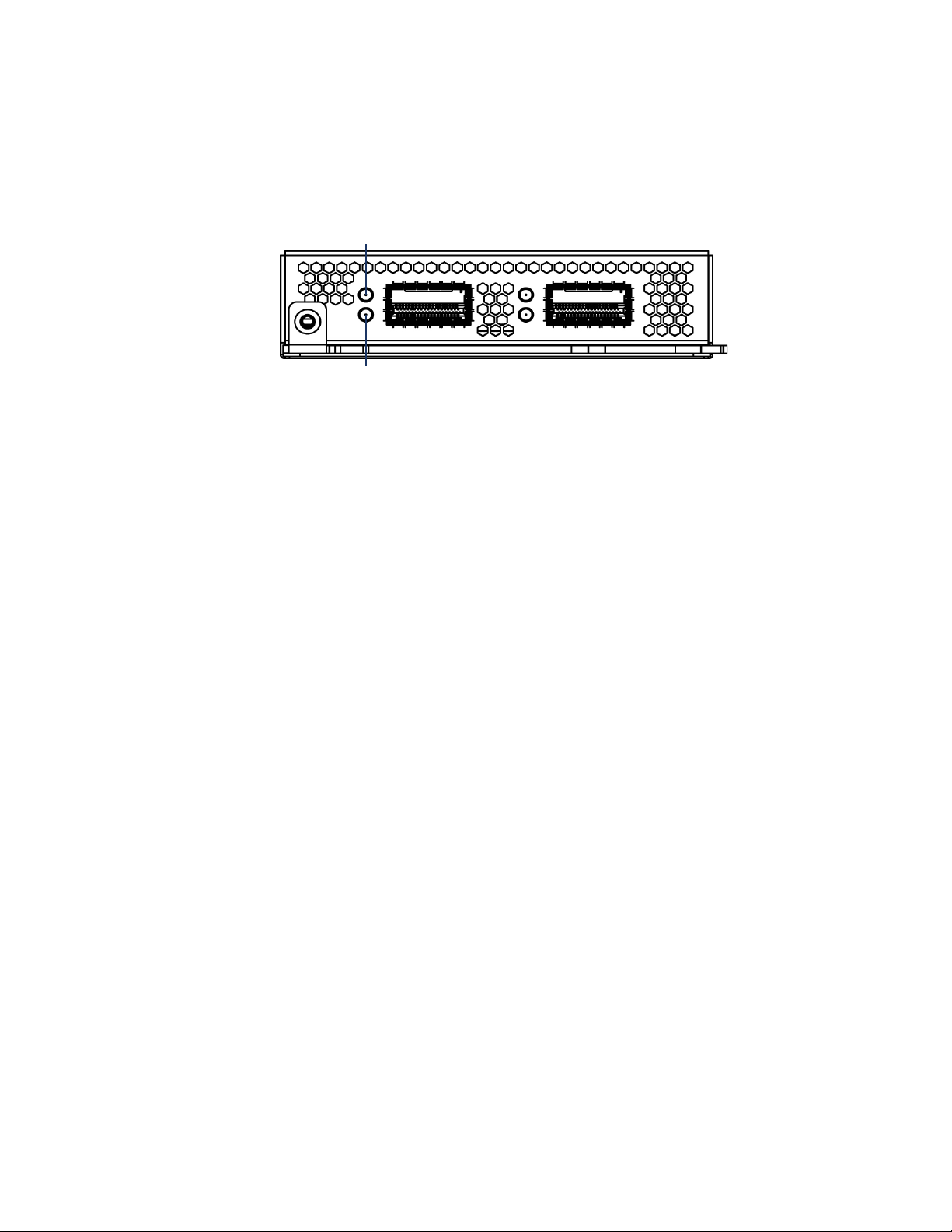
Installing a 3D Sensor
Activity
Link
Identifying the Management and Sensing Interfaces
Stacking Module
You can increase the amount of traffic inspected on a network segment by
connecting two 3D8140 sensors in a stacked sensor configuration to combine
their resources into a single, shared configuration.
One sensor is designated as primary and the other is secondary. Connect the
primary sensor to the network segment you want to analyze in the same way you
would configure a single 3D8140 sensor (either passive, inline, or inline with
fail-open). Connect a secondary sensor to the primary sensor using one
8000 Series cable. Use a Defense Center to establish the stacked relationship
between the sensors and manage their joint resources. For more information on
establishing the stacked configuration, see Using 3D Sensors in a Stacked
Configuration on page 55. For more information on managing the stacked
configuration, see “Managing a Stacked Pair” in the Sourcefire 3D System User
Guide.
Chapter 2
Sourcefire 3D Sensor 8250/8260/8270/8290
The 3D8250/8260/8270/8290 3D Sensor is a 2U, 4U, 6U, or 8U appliance, as
follows:
• a 2U 3D8250 (a 10G-capable sensor)
• a 4U 3D8260 (a 10G-capable primary sensor and a secondary sensor)
• a 6U 3D8270 (a 40G-capable primary sensor and two secondary sensors)
• a 8U 3D8290 (a 40G-capable primary sensor and three secondary sensors)
The sensor can be shipped fully assembled, or you can install the sensing
interface modules into the chassis. For the 3D8260/8270/8290, sensing interface
modules are installed in the primary sensor only. The 40G sensing interface
module must be installed in 40G-capable sensors only. Assemble your sensor
before installing the Sourcefire 3D System. See the assembly instructions
Version 4.10.3 Sourcefire 3D Sensor Installation Guide 48

Installing a 3D Sensor
Management Interface
Module Slots
4
5
7
1
2
3
6
Identifying the Management and Sensing Interfaces
shipped with your modules.The following illustration of the rear view of the
3D8250 and 3D8260 chassis indicates the location of the management interface.
The following illustration of the front view of the chassis indicates the location of
the sensing interfaces.
Chapter 2
Modules
The 3D8250 sensor can be delivered with the following modules:
• a quad-port 1000BASE-T copper interface with bypass capability. See Dual
Quad-Port 1000BASE-T Copper Bypass Sensing Interfaces on page 43.
• a dual-port 10GBASE (MMSR or SMLR) fiber interface with bypass
capability. See Dual-Port 10GBASE (MMSR or SMLR) Fiber Bypass NetMod
on page 46 for more information.
• a quad-port 1000BASE-SX fiber interface with bypass capability. See
Quad-Port 1000BASE-SX Fiber Bypass NetMod on page 47 for more
information.
• a dual-port 40GBASE-SR4 fiber interface with bypass capability. See
Dual-Port 40GBASE-SR4 Fiber Bypass NetMod on page 52 for more
information.
• a stacking module used to stack up four identical 3D8250 sensors to
increase detection resources. See Stacking Module on page 48.
Version 4.10.3 Sourcefire 3D Sensor Installation Guide 49

Installing a 3D Sensor
Link LED
Activity LED
Bypass LED
Link LED Ports Bypass LED
Activity LED
Identifying the Management and Sensing Interfaces
Quad-Port 1000BASE-T Copper Bypass NetMod
The quad-port 1000BASE-T copper bypass configuration uses Ethernet cables.
You can use these connections to passively monitor up to four separate network
segments. You also can use paired interfaces in inline or inline with fail-open
mode, which allows you to deploy the 3D Sensor as an intrusion prevention
system on up to two separate networks.
If you want to take advantage of the sensor’s automatic fail-open capability, you
must connect either the two interfaces on the left or the two interfaces on the
right to a network segment. Automatic fail-open capability allows traffic to flow
even if the sensor fails or loses power. After you cable the interfaces, you use the
web interface to configure the interface set as inline with fail open.
If you configure the interfaces as inline without using the fail-open capability, you
can use any two sensing interfaces (even nonconsecutive interfaces) as an inline
pair.
Chapter 2
Dual-Port 10GBASE (MMSR or SMLR) Fiber Bypass NetMod
The dual-port 10GBASE fiber bypass configuration uses LC-type (Local Connector)
optical transceivers. Note that these can be either MMSR or SMLR interfaces.
You can use this configuration to passively monitor up to two separate network
segments. You also can use paired interfaces in inline or inline with fail open
Version 4.10.3 Sourcefire 3D Sensor Installation Guide 50

Installing a 3D Sensor
Ports Bypass LEDLink LEDs
Activity LEDs
Identifying the Management and Sensing Interfaces
mode, which allows you to deploy the 3D Sensor as an intrusion prevention
system on a single network.
TIP! For best performance, use the interface sets consecutively. If you skip any
interfaces, you may experience degraded performance.
If you want to take advantage of a sensor’s automatic fail-open capability, you
must connect the two interfaces on the left or the two interfaces on the right to a
network segment. Automatic fail-open capability allows traffic to flow even if the
sensor fails or loses power. After you cable the interfaces, you use the web
interface to configure the interface set as inline with fail open.
If you configure the interfaces as inline without using the fail-open capability, you
can use any two of the interfaces as an inline pair.
Quad-Port 1000BASE-SX Fiber Bypass NetMod
Chapter 2
The quad-port 1000BASE-SX fiber bypass configuration uses LC-type (Local
Connector) optical transceivers.
You can use this configuration to passively monitor up to four separate network
segments. You also can use paired interfaces in inline or inline with fail open
mode, which allows you to deploy the 3D Sensor as an intrusion prevention
system on up to two separate networks.
TIP! For best performance, use the interface sets consecutively. If you skip any
interfaces, you may experience degraded performance.
If you want to take advantage of a sensor’s automatic fail-open capability, you
must connect the two interfaces on the left or the two interfaces on the right to a
network segment. Automatic fail-open capability allows traffic to flow even if the
sensor fails or loses power. After you cable the interfaces, you use the web
interface to configure the interface set as inline with fail open.
If you configure the interfaces as inline without using the fail-open capability, you
can use any two of the interfaces as an inline pair.
Version 4.10.3 Sourcefire 3D Sensor Installation Guide 51

Installing a 3D Sensor
Link LED
Port
Bypass LED
Activity LED
Activity
Link
Identifying the Management and Sensing Interfaces
Dual-Port 40GBASE-SR4 Fiber Bypass NetMod
The dual-port 40GBASE-SR4 fiber bypass configuration uses MPO (Multiple-Fiber
Push On) connector optical transceivers.
You can use the 40G NetMod only in the 3D8270/8290 or a 40G-capable
3D8250/8260. If you attempt to create a 40G interface on a sensor that is not
40G-capable, the 40G interface screen on its managing Defense Center web
interface displays red. A 40G-capable sensor displays
Panel
You can use this configuration to passively monitor up to two separate network
segments. You also can use the paired interface in inline or inline with fail-open
mode, which allows you to deploy the 3D Sensor as an intrusion prevention
system on one network.
If you want to take advantage of a sensor’s automatic fail-open capability, you
must use the web interface to configure the interface set as inline with fail-open.
Chapter 2
3D 8250-40G on the LCD
Stacking Module
The stacking module uses two 8000 Series cables for each stacking module.
You can increase the amount of traffic inspected on a network segment by
connecting up to four 3D8250 sensors in a stacked sensor configuration to
combine their resources into a single, shared configuration. Note that the 3D8260
contains a 3D8250 primary sensor and a dedicated secondary sensor for
stacking.
Version 4.10.3 Sourcefire 3D Sensor Installation Guide 52

Installing a 3D Sensor
Management Interface (eth0)
Sensing Interfaces
Identifying the Management and Sensing Interfaces
One sensor is designated as primary and the others are secondary. Connect the
primary sensor to the network segment you want to analyze in the same way you
would configure a single 3D8250 sensor (either passive, inline, or inline with failopen). Connect the secondary sensor (another 3D8250 or the dedicated
secondary sensor in the 3D8260) to the primary sensor using two 8000 Series
cables. Use a Defense Center to establish the stacked relationship between the
sensors and manage their joint resources. For more information on establishing
the stacked configuration, see Using 3D Sensors in a Stacked Configuration on
page 55. For more information on managing the stacked configuration, see
“Managing a Stacked Pair” in the Sourcefire 3D System User Guide.
Sourcefire 3D Sensor 9900
The 3D9900 3D Sensor is a 2U appliance and is also referred to as a Series 2
sensor. The following illustration indicates the location of the management
interface, which is on the rear of the chassis.
Chapter 2
The following illustration indicates the location of the sensing interfaces, which
are on the front of the chassis.
Version 4.10.3 Sourcefire 3D Sensor Installation Guide 53

Installing a 3D Sensor
ethb0
ethb11
ethb1 ethb2 ethb3
ethb4 ethb5 ethb6 ethb7 ethb8 ethb9 ethb10
Identifying the Management and Sensing Interfaces
The 3D9900 appliance can be delivered with two different sensing interface
configurations:
• Twelve-port configurations for 10/100/1000 copper bypass; see Twelve-Port
Copper Configuration on page 54 for more information
• Four-port 10Gb fiber bypass configuration; see Four-Port 10Gb Fiber
Configuration on page 54 for more information
Twe lv e-Port Copper Configuration
The 3D9900 12-port configuration contains 12 1Gb copper interfaces.The
following illustration indicates the interface numbering.
You can use these interfaces to passively monitor up to 12 separate network
segments. You also can use paired interfaces in inline or inline with fail open
mode, which allows you to deploy the 3D Sensor as an intrusion prevention
system on up to six networks.
Chapter 2
TIP! For the best performance, you must use the interfaces consecutively,
starting with
performance.
If you want to take advantage of a sensor’s automatic fail-open capability, you
must connect adjacent interfaces (
on) to a network segment. This allows traffic to flow even if the sensor fails or
loses power. You must also use the web interface to configure the interface set
as inline with fail open.
By default, the initial setup process supports six inline fail-open interface pairs. If
you want to use passive or other configurations, see “Using Detection Engines
and Interface Sets” in the Sourcefire 3D System User Guide.
ethb0. If you skip any interfaces, you may experience degraded
ethb0 with ethb1, ethb2 with ethb3, and so
Four-Port 10Gb Fiber Configuration
The 3D9900 sensor also supports a four-port bypass configuration for 10Gb fiber
media. It uses uses LC-type (Local Connector) optical transceivers. Note that
these are SR interfaces. The following illustration indicates the interface
Version 4.10.3 Sourcefire 3D Sensor Installation Guide 54

Installing a 3D Sensor
ethb0 ethb3ethb1 ethb2
Using 3D Sensors in a Stacked Configuration
numbering for the two leftmost interfaces: ethb0 and ethb1. The two interfaces
on the right are
You can use this configurations to passively monitor up to four separate network
segments. You also can use paired interfaces in inline or inline with fail open
mode, which allows you to deploy the 3D Sensor as an intrusion prevention
system on up to four networks.
TIP! For the best performance, you must use the interfaces consecutively,
starting with
performance.
ethb2 and ethb3.
ethb0. If you skip any interfaces, you may experience degraded
Chapter 2
If you want to take advantage of a sensor’s automatic fail-open capability, you
must connect the two interfaces on the left or the two interfaces on the right to a
network segment. Automatic fail-open capability allows traffic to flow even if the
sensor fails or loses power. After you cable the interfaces, you use the web
interface to configure the interface set as inline with fail open.
Using 3D Sensors in a Stacked Configuration
Increase the amount of traffic inspected on network segments by combining the
resources of identically-configured sensors in a stacked configuration.
Use a Defense Center to establish the relationship between the stacked sensors
and manage the resources of the stacked sensors. After the stacked relationship
is established, each device inspects traffic separately using a single, shared
detection configuration.
You can create the following stacked configurations:
• two fiber-based 3D9900 sensors
• two 3D8140 sensors
• up to four 3D8250 sensors
• a 3D8260 (a 10G-capable primary sensor and a secondary sensor)
• a 3D8270 (a 40G-capable primary sensor and two secondary sensors)
• a 3D8290 (a 40G-capable primary sensor and three secondary sensors)
For the 3D8260 and 3D8270, you can stack additional sensors for a total of four
sensors in the stack.
Version 4.10.3 Sourcefire 3D Sensor Installation Guide 55

Installing a 3D Sensor
Using 3D Sensors in a Stacked Configuration
One sensor is designated as the primary sensor and is displayed on the web
interface with the primary role. All other sensors are secondary and are displayed
in the web interface with the secondary role. You use the combined detection
engines as a single entity except when viewing information from the stacked
sensors.
Connect the primary sensor to the network segments you want to analyze in the
same way that you would connect a single 3D9900, 3D8140, or 3D8250 sensor
(either passive, inline, or inline with fail-open). Connect the secondary sensor to
the primary sensor as indicated by the sensor’s stack cabling diagram.
After the sensors are physically connected to the network segments and to each
other, use a Defense Center to establish the stacked sensor relationship and
manage their joint resources. For information on connecting the primary and
secondary stacking sensors, see the following sections:
• Connecting 3D9900 Sensors on page 56
• Connecting 3D8140 Sensors on page 58
• Connecting 3D8250/8260/8270/8290 Sensors on page 58
• Using the 8000 Series Stacking Cable on page 62
Use the Defense Center that manages your stacked sensors to create, edit, and
list the detection engines of stacked sensors. You cannot manage detection
engines or interface sets on the local web interface of a stacked sensors; the Edit
page is replaced with an informational page.
Chapter 2
If the primary sensor fails, traffic is handled according to the configuration of the
primary sensor (either passive, inline, or inline with fail-open). A health alert is
generated indicating loss of link.
If the secondary sensor fails, the primary sensor continues to sense traffic,
generate alerts, and send traffic to the failed secondary sensor where the traffic
is dropped. A health alert is generated indicating loss of link.
For information on establishing and managing stacked sensors, see the following
sections:
• “Managing Stacked Sensors” in the Sourcefire 3D System User Guide
explains how to use a Defense Center to establish, manage, and separate
stacked sensors.
• “Understanding Detection Engines and Interface Sets” in the Sourcefire 3D
System User Guide explains how to use the resources on stacked sensors.
Connecting 3D9900 Sensors
You can connect two 3D9900 sensors in a stacked configuration. Use 10G LC
fiber cables to create the physical connection between the primary and
secondary sensors.
Install the sensors in your rack so that you can easily connect the cables between
the stacking modules. Connect the primary sensor to the network segment you
Version 4.10.3 Sourcefire 3D Sensor Installation Guide 56

Installing a 3D Sensor
Primary Sensor
Secondary Sensor
Using 3D Sensors in a Stacked Configuration
want to analyze in the same way that you would connect a single 3D9900 sensor
(either passive, inline, or inline with fail-open). The following graphic shows how
to connect the primary and secondary sensors.
Use the Stack Interconnect table as a guide for cabling the interfaces on the
primary and secondary sensors.
Chapter 2
Stack Interconnect
Primary
Sensor
Interface
ethb2 RX ethb0 TX
ethb2 TX ethb0 RX
ethb3 RX ethb1 TX
ethb3 TX ethb1 RX
To connect a 3D9900 secondary sensor:
1. Connect the interfaces on the primary sensor to the interfaces on the
secondary sensor as indicated in the graphic and the Stack Interconnect
table.
2. Use a Defense Center to establish the stacked sensor relationship and
manage their joint resources. See “Managing Stacked Sensors” in the
Sourcefire 3D System User Guide.
Secondary
Sensor
Interface
Version 4.10.3 Sourcefire 3D Sensor Installation Guide 57

Installing a 3D Sensor
Secondary Sensor
Primary Sensor
3D8140 Primary Sensor with One Secondary Sensor
Using 3D Sensors in a Stacked Configuration
Connecting 3D8140 Sensors
You can connect two 3D8140 sensors in a stacked configuration. Use one
8000 Series stacking cable to create the physical connection between the
primary sensor and the secondary sensor. For more information on using the
stacking cable, see Using the 8000 Series Stacking Cable on page 62.
Install the sensors in your rack so that you can easily connect the cable between
the stacking modules. You can install the secondary sensor above or below the
primary sensor.
Connect the primary sensor to the network segments you want to analyze in the
same way that you would connect a single 3D8140 sensor (either passive, inline,
or inline with fail-open). Connect the secondary sensor directly to the primary
sensor.
The following graphic shows a primary sensor and a secondary sensor. In this
example, the secondary sensor is installed below the primary sensor.
Chapter 2
To connect a 3D8140 secondary sensor:
1. Connect the left stacking interface on the primary sensor to the left stacking
interface on the secondary sensor.
2. Use a Defense Center to establish the stacked sensor relationship and
manage their joint resources. See “Managing Stacked Sensors” in the
Sourcefire 3D System User Guide.
Connecting 3D8250/8260/8270/8290 Sensors
You can create the following stacked configurations:
• up to four 3D8250 sensors
• a 3D8260 (a 10G-capable primary sensor and a secondary sensor)
• a 3D8270 (a 40G-capable primary sensor and two secondary sensors)
• a 3D8290 (a 40G-capable primary sensor and three secondary sensors)
For the 3D8260 and 3D8270, you can stack additional sensors for a total of four
sensors in the stack.
Version 4.10.3 Sourcefire 3D Sensor Installation Guide 58

Installing a 3D Sensor
Primary Sensor
Secondary Sensor
3D8250 Primary Sensor with One Secondary Sensor
Primary Sensor
Secondary Sensor
3D8260 - 3D8250 Primary Sensor and Dedicated Secondary Sensor
Using 3D Sensors in a Stacked Configuration
Use two 8000 Series stacking cables for each secondary sensor you want to
connect to the primary sensor. Note that sensors do not need to be powered
down to attach the cables. For more information on using the stacking cable, see
Using the 8000 Series Stacking Cable on page 62.
Install the sensors in your rack so that you can easily connect the cables between
the stacking modules. You can install the secondary sensors above or below the
primary sensor.
Connect the primary sensor to the network segments you want to analyze in the
same way that you would connect a single 3D8250 sensor (either passive, inline,
or inline with fail-open). Connect each secondary sensor directly to the primary
sensor as required for the number of secondary sensors in the configuration.
The following example shows a primary sensor with one secondary sensor. In
this example, the secondary sensor is installed below the primary sensor.
Chapter 2
Version 4.10.3 Sourcefire 3D Sensor Installation Guide 59
The following example shows a 3D8260 configuration which includes a 3D8250
primary sensor and a dedicated secondary sensor. In this example, the secondary
sensor is installed below the primary sensor.

Installing a 3D Sensor
Secondary Sensor
Secondary Sensor
Primary Sensor
3D8270 - 3D8250 Primary Sensor with Two Secondary Sensors
Using 3D Sensors in a Stacked Configuration
Use additional stacking modules in the 3D8250 to add more secondary sensors
to the configuration.
The following example shows a primary sensor with two dedicated secondary
sensors. In this example, the primary sensor is installed above the two secondary
sensors.
Chapter 2
Version 4.10.3 Sourcefire 3D Sensor Installation Guide 60

Installing a 3D Sensor
Primary Sensor
Secondary Sensor
Secondary Sensor
Secondary Sensor
3D8290 - 3D8250 Primary Sensor with Three Secondary Sensors
Using 3D Sensors in a Stacked Configuration
The following example shows a primary sensor with three dedicated secondary
sensors. In this example, one secondary sensor is installed above the primary
sensor and two secondary sensors are installed below the primary sensor.
Chapter 2
Version 4.10.3 Sourcefire 3D Sensor Installation Guide 61
To connect a 3D8250 secondary sensor:
1. Connect the left stacking interface on the primary sensor to the left stacking
interface on the secondary sensor.
2. Connect the right stacking interface on the primary sensor to the right
stacking interface on the secondary sensor.
3. Repeat steps 1 and 2 for each secondary sensor you want to connect.
4. Use a Defense Center to establish the stacked sensor relationship and
manage their joint resources. See “Managing Stacked Sensors” in the
Sourcefire 3D System User Guide.

Installing a 3D Sensor
Latch Release Tab
Latch
Keyed Cable End
Installing the 3D Sensor in a Rack
Using the 8000 Series Stacking Cable
The 8000 Series stacking cable has identically-keyed ends, each with a latch to
secure the cable in the sensor and a latch release tab.
Use 8000 Series stacking cables to create the physical connection between the
primary sensor and each secondary sensor as required for each sensor
configuration. The 3D8140 requires one cable per connection, and the
3D8250/8260/8270/8290 requires two cables per connection. Sensors do not
need to be powered down to insert or remove the stacking cables.
WARNING! Use only the Sourcefire 8000 Series stacking cable when cabling
your devices. Using unsupported cables can create unforeseen errors.
Chapter 2
Use the Defense Center to manage the stacked sensors after you have physically
connected the sensors.
To insert an 8000 Series stacking cable:
To insert the cable, hold the cable end with release tab facing up and insert
the keyed end into the port on the stacking module until you hear the latch
click into place.
To remove an 8000 Series stacking cable:
To remove the cable, pull on the release tab to release the latch, and remove
the cable end.
Installing the 3D Sensor in a Rack
The 3D Sensor is delivered on different hardware appliances. Make sure you refer
to the correct illustration for your appliance as you follow the installation
procedure.
Version 4.10.3 Sourcefire 3D Sensor Installation Guide 62

Installing a 3D Sensor
Installing the 3D Sensor in a Rack
To install the appliance:
1. Mount the appliance in your rack using the mounting kit. Use the instructions
supplied with the mounting kit.
IMPORTANT! You may also use the 3D500, 3D1000, and 3D2000 appliances
as desktop devices.
2. Attach the power cord to the appliance and plug it into a power source.
IMPORTANT! If your appliance has redundant power supplies, attach power
cords to both power supplies and plug them in.
Note that some models of the 3D Sensor automatically boot up when they
are provided with power.
3. Use an Ethernet cable to connect the management interface to a protected
network segment. The default IP address of the management interface is
192.168.45.45 with a Netmask of 255.255.255.0.
Chapter 2
4. Connect the sensing interfaces to the network segments you want to analyze
using either copper or fiber cables, whichever is appropriate.
In general, if you are using your 3D Sensor for RNA or RUA only, you can use
straight-through cables to connect the sensing interfaces to your network.
If you are using your 3D Sensor for IPS or for IPS plus another component,
see Issues for Copper Cabling in Inline Deployments on page 27 for
information about deciding when to use straight-through or crossover cables
to connect the sensor interfaces to your network.
Version 4.10.3 Sourcefire 3D Sensor Installation Guide 63

Installing a 3D Sensor
Configuring the Management Interface
If you are deploying a sensor with fail-open interfaces, you are taking
advantage of your sensor’s ability to maintain network connectivity even if
the sensor goes down. See Testing an Inline Fail-Open Interface Installation
on page 76 for more information on installation and latency testing.
• Fiber Adapter Card: For 3D Sensors with a fiber adapter card, connect
the LC connectors on the optional multimode fiber cable to two ports
on the adapter card in any order. Connect the SC plug to the network
segment you want to analyze.
• Fiber Tap: If you are deploying the 3D Sensor with an optional fiber
optical tap, connect the SC plug on the optional multimode fiber cable
to the “analyzer” port on the tap. Connect the tap to the network
segment you want to analyze.
• Copper Tap: If you are deploying the 3D Sensor with an optional copper
tap, connect the A and B ports on the left of the tap to the network
segment you want to analyze. Connect the A and B ports on the right of
the tap (the “analyzer” ports) to two copper ports on the adapter card.
For more information about options for deploying the 3D Sensor, see Ty pi ca l
3D Sensor Deployments on page 11.
Chapter 2
5. If your 3D Sensor has a power switch, turn on the sensor and continue with
the next section, Configuring the Management Interface on page 64
WARNING! Make sure that no USB devices are plugged into a 3D9900
Sensor prior to powering up the appliance, as that will silently change the
BIOS boot order.
Configuring the Management Interface
In this section, you set up the IP address and network settings for the
management interface that you will use later to administer the appliance.
For Series 2 and Series 3 appliances, you can use the following options:
• Using the Management Interface on page 65 explains how to connect a
host such as a laptop directly to the management interface to configure the
interface’s settings.
• Using a Monitor and Keyboard on page 66 explains how to connect a
monitor and keyboard to the rear of the appliance, and then run a script to
help you configure the interface’s settings.
IMPORTANT! For the 7000 Series appliances only, you must disable the
Spanning Tree protocol on any port intended for use with Serial Over LAN.
Version 4.10.3 Sourcefire 3D Sensor Installation Guide 64

Installing a 3D Sensor
Configuring the Management Interface
For Series 3 appliances only, you can also use the following options:
• Using the LCD Panel on page 68 explains how to use the LCD Panel to
configure the management interface for the appliance.
• Using the Command Line Interface on page 71 explains how to use the
command line to enter the network configuration, and register the sensor to
a Defense Center.
IMPORTANT! Use the command line interface as needed only during the
installation configuration.
Using the Management Interface
Use this process on Series 2 and Series 3 sensors.
The appliance is preconfigured with a default IPv4 address. This option is useful if
you have a local host (for example a laptop computer) that you can physically
connect to the management interface with an Ethernet cable. You can then use a
web browser to navigate directly to the appliance and complete the initial setup
process.
Chapter 2
If you want to configure your management interface with an IPv6 address, you
have two options: connect to your management interface with this preconfigured
IPv4 address and reconfigure to an IPv6 address, or connect manually by Using a
Monitor and Keyboard and configure with an IPv6 address.
To connect directly to the management interface:
1. Power up the appliance but do not log into the appliance.
2. Configure a local host (for example, a laptop computer) with the following
network settings:
• IP address:
• Netmask: 255.255.255.0
• Default Gateway: 192.168.45.1
Note that your local host must not be connected to the Internet.
3. Use an Ethernet cable to connect the network interface on the local host to
the management interface on the appliance.
Confirm that the link LED is on for both the network interface on the local
host and the management interface on the sensor.
TIP! If the management interface and network interface LEDs are not lit, use
a cross-over cable instead of a standard Ethernet cable to connect the two
appliances.
192.168.45.2
Version 4.10.3 Sourcefire 3D Sensor Installation Guide 65

Installing a 3D Sensor
Configuring the Management Interface
4. Use the web browser on the local host to navigate to the appliance’s default
IP address:
https://192.168.45.45/
The Login page appears.
TIP! You may need to add an exception to your trusted sites on your browser
before you can access the login page. Follow the instructions on your
browser to allow the exception.
Chapter 2
5. Log into the web interface using
as the password. Note that the password is case sensitive.
On the local host, log into the web interface using
and
Sourcefire as the password. Note that the password is case sensitive.
The Install page appears. Continue with Performing the Initial Setup on
page 72.
Using a Monitor and Keyboard
Use a monitor and keyboard on Series 2 and Series 3 sensors to configure the
management interface on the appliance.
The appliance is delivered with monitor and keyboard connectors on the rear of
the appliance. This option is useful if your facility has a spare monitor and
keyboard or if you routinely use a KVM switch to access your appliances. With
this option you must run a script to preset the network settings for the
management interface before you begin the initial setup process.
The script will prompt you for the following information about the management
interface and your network environment:
• the IP address you want to give to the management interface
• the netmask for the management interface’s IP address
• the default gateway for the management interface
admin as the username and Source fire
admin as the username
Version 4.10.3 Sourcefire 3D Sensor Installation Guide 66

Installing a 3D Sensor
Configuring the Management Interface
To use a monitor and keyboard:
1. Using the supplied Ethernet cable, connect the management interface on the
rear of the appliance to a protected management network.
2. Connect a monitor and keyboard to the appliance.
Connect the monitor to the VGA port and the keyboard to one of the USB
ports (or optionally to the PS/2 keyboard connector, if available).
TIP! If you later want to create a serial connection between the appliance
and a computer running terminal emulation software such as Microsoft
Windows Hyperterminal or XModem, you must enter
/usr/local/sf/bin/set_console.sh -c ttyS1, then reboot the appliance.
Then, set your emulation software to use 9600 baud, 8 data bits, no parity
checking, 1 stop bit, and no flow control. For more information, see
Redirecting Console Output on page 75.
Chapter 2
3. Log in as
admin.
The system requests a password.
4. Enter
Sourcefire as the password.
Note that the password is case sensitive.
5. Typ e
sudo su - and press Enter. If needed, type the admin account
password and press Enter to approve the command and display the root
prompt.
6. Run the following script:
/usr/local/sf/bin/configure-network
The following prompt appears:
Do you wish to configure IPv4? (y or n)
7. Ty p e y and press Enter to configure the appliance with an IPv4 address.
The following prompt (appended with the current value) appears:
Management IP address?
8. Enter the IP address you want to assign to the management interface or
press Enter to accept the current value. For example:
10.2.2.20
The following prompt (appended with the current value) appears:
Management netmask?
9. Enter the netmask for the interface’s IP address or press Enter to accept the
current value. For example:
255.255.0.0
The following prompt appears:
Management default gateway?
Version 4.10.3 Sourcefire 3D Sensor Installation Guide 67

Installing a 3D Sensor
Multi-Function Keys
Function Symbols
Configuring the Management Interface
10. Enter the IP address of the gateway for this IP address. For example:
10.2.1.1
The following prompt appears:
Are these settings correct: (y or n)?
11. You have two options:
• If the settings are correct, type
• If the settings are incorrect, type
to enter the information again.
12. After you enter the correct network settings for the management interface,
type
exit and press Enter to log out of root.
13. Ty p e logout and press Enter to log out of the appliance, and disconnect the
monitor and keyboard.
Continue with Performing the Initial Setup on page 72.
Using the LCD Panel
Chapter 2
y and press Enter to continue.
n and press Enter. You are prompted
Use the LCD Panel on Series 3 sensors only to configure the management
interface on the appliance.
A symbol and its location on the display correspond to its function and the
location of the key used to perform that function. If no symbol is shown, the
corresponding key has no function.
The IPv4 address is prepopulated with your IP address. IPv6 displays all zeros. As
an example, an initial IPv4 configuration looks something like this:
IPv4 Address: - +
94.170.001.001 X >
1
The first line indicates that you are editing the IPv4 address. The second line
displays the IPv4 address you are editing. The two symbols at the end of each
row indicate the actions associated with the two keys to the right of each row.
In the example above, you can perform the following actions;
• Use the left key on the first row
• Use the right key on the first row
• Use the left key on the second row
• Use the right key on the second row
(-) to decrease the digit by one.
(+) to increase the digit by one.
(X) to cancel the action.
(>) move the cursor to the right.
Version 4.10.3 Sourcefire 3D Sensor Installation Guide 68

Installing a 3D Sensor
Configuring the Management Interface
The cursor appears only on the second line, and indicates where on the display
you are editing. Note that when the cursor is not located at the first digit, the
panel displays a left
your cursor to the left.
You can edit standard network setup information for either IPv4 or IPv6. IPv4 is
enabled and preconfigured by default.
The Initial Setup/Network Configuration table lists configurable information.
Initial Setup/Network Configuration
IPv4 (default) IPv6
IP address IP address
Netmask Prefix
Subnet Mask Default Gateway
Chapter 2
(<) arrow, and using the corresponding function key moves
Note that the displays for editing the Netmask, Prefix, Subnet Mask, and Default
Gateway function in the same manner as the IP address display. For more
information on using the multi-function keys, see Using the Multi-Function Keys
on page 85.
To configure the network:
1. Press any of the multi-function keys to activate the keys on the LCD Panel.
The following screen is displayed:
Network Config >
System Status < >
2. Press the right arrow at the end of the Network Config line. The following
screen is displayed:
IPv4 < >
IPv6 >
3. Press the right arrow to select either IPv4 or IPv6, or press the left arrow to
return to the previous screen.
For IPv4, the following screen is displayed:
IPv4 set to DHCP <
Enable Manual? >
IPv6 displays a similar screen.
4. Press the right arrow to select
from the LCD Panel. Selecting
Manual to enter the network configuration
DHCP returns to the previous screen.
An IP address screen displays all zeros in the IP address The example shows
IPv4:
IPv4 address: - +
00.000.000.000 x >
0
Version 4.10.3 Sourcefire 3D Sensor Installation Guide 69

Installing a 3D Sensor
Configuring the Management Interface
5. Use the multi-function keys to move the cursor left or right until you reach the
digit in the IP address you want to edit.
Initially, the cursor is located at the far left of the display and the cancel (X)
symbol is displayed instead of the left (<) arrow. As soon as you move the
cursor to the right, the cancel (X) symbol changes to a left (<) arrow.
6. Increase or decrease the value of the digit by using the minus and plus keys.
Edit each digit as necessary to the end of the IP address. Use leading zeroes
as needed. The following example uses the preconfigured IPv4 address.
IPv4 address: - +
192.168.045.045 < >
An IPv6 address does not display fully on the LCD Panel. Scroll right or left as
needed until you have entered the entire address, then scroll to the last digit
in the address.
7. After you configure the final digit, press the right arrow once more to display
the function keys (such as Cancel and Accept on the top row and Return on
the bottom row).
IPv4 address: x
192.168.045.045 <
Chapter 2
8. You have three options:
• Press (X) to cancel the configuration and return to the previous menu.
• Press the check mark () to accept and move to the next configuration.
• Press the left arrow (<) to return to editing the current configuration.
You must accept the displayed configuration to continue to the next display.
9. On the Netmask display, configure Netmask using the same process you
used to configure the IP address. See steps 5 through 8 for more information.
10. On the Subnet Mask display, configure the address of the gateway using the
same process you used to configure the IP address. See steps 5 through 8
for more information.
11. After you accept the Subnet Mask display, you are prompted to save the
configuration:
Save? x
Press the check mark () to accept the networking configuration.
Continue with Performing the Initial Setup on page 72.
Version 4.10.3 Sourcefire 3D Sensor Installation Guide 70

Installing a 3D Sensor
Configuring the Management Interface
Using the Command Line Interface
Use the command line interface on Series 3 sensors only to configure the
management interface on the appliance.
Series 3 sensors must be managed by a Defense Center. A unique alphanumeric
registration key is always required. In most cases, to register a sensor to a
Defense Center, you must provide the hostname and the IP address along with
the registration key. You can register the sensor to a Defense Center using the
command line, or you can register the sensor later.
You must connect a monitor and keyboard to the rear of the appliance. At the
prompts, you must provide the following for the following information about the
management interface and your network environment:
• the IP address you want to give to the management interface
• the netmask for the management interface’s IP address
• the default gateway for the management interface
To complete the initial setup using the command line interface:
Chapter 2
1. Connect a monitor and keyboard to the appliance using the ports at the rear
of the appliance.
2. At the
3. You must accept the EULA. Read and accept the EULA to continue.
4. Using the prompts on the screen, perform these actions. Options are listed in
Sourcefire 3D Login prompt, enter admin followed by Sourcefire
for the login and password. Note that both login and password are
case-sensitive.
The EULA acceptance screen appears.
parenthesis, such as
[y]
. If you accept all defaults, the procedure is as follows:
• change the admin password:
password
• configure IPv4: (y/n): [y]
• configure IPv6: (y/n): [n]
• configure IPv4 via DHCP or manually: (dhcp/manual) [manual]
• enter an IPv4 address for the management interface
[
XxX.XxX.XxX.XxX
• enter an IPv4 netmask for the management interface
[
XxX.XxX.XxX.XxX
• enter an IPv4 default gateway for the management interface
[
XxX.XxX.XxX.XXX
• enter a fully qualified hostname for this system [
(y/n). Defaults are listed in square brackets, such as
enter new password; confirm new
]
]
]
hostname.com
]
Version 4.10.3 Sourcefire 3D Sensor Installation Guide 71

Installing a 3D Sensor
Performing the Initial Setup
5. To configure the sensor to accept a Defense Center as manager, use the
Chapter 2
• enter a comma-separated list of DNS servers or ‘none’
[
XxX.XXx.XXx.XXx, XxX.XxX.XxX.XxX
• enter a comma-separated list of search domains or ‘none’
[
searchdomain.com
• Set permission for the LCD Panel to reconfigure the network. Note that
allowing the LCD Panel to configure network settings poses a security
risk because no authentication is needed, only physical access.
Allow LCD Panel to configure network settings? (y/n) [n]: n
following command:
configure manager add [
key
]
However, if the sensor and the Defense Center are separated by a NAT
device, you must enter a unique NAT ID, along with the registration key.
configure manager and DONTRESOLVE [
registration key
[
The registration key is a unique user-generated alpha-numeric key used to
register a sensor to a Defense Center. When you complete the sensor
registration on the Defense Center’s web interface, you must use the same
registration key and, if necessary, the same NAT ID when you add this sensor
to the Defense Center.
]
hostname
]
]
|
ip address
hostname
] [
registration
|
ip address
]
6. Typ e
logout and press Enter to log out of the appliance.
Continue with Performing the Initial Setup on page 72.
Performing the Initial Setup
After you physically install the 3D Sensor and set up the IP address for the
management interface, you can log into the 3D Sensor’s web interface. When
you first log into the 3D Sensor, the Install page appears where you can continue
the setup process. After you perform the initial setup, see the Sourcefire 3D
System User Guide for information about the next steps you need to take.
WARNING! Prepare for the initial setup and complete it promptly after you begin.
If the initial setup is interrupted or if a second user logs in while the initial setup is
underway, the results can be unpredictable.
Version 4.10.3 Sourcefire 3D Sensor Installation Guide 72

Installing a 3D Sensor
Performing the Initial Setup
To complete the initial setup:
1. From a host with a web browser that can reach the appliance’s management
interface on the protected management network, navigate to:
https:
where
procedure.
The appliance’s Login page appears.
//mgt_ip_address/
mgt_ip_address
is the IP address you set up in the previous
Chapter 2
2. Log into the web interface using
the password. Note that the password is case sensitive.
3. Under Change Password, in the New Password and Confirm fields, enter a new
password for the admin user account and for the admin password for the
shell account. The same password is used for both accounts.
TIP! The initial change to the admin user password changes the admin
password for the shell account. Use the command line interface on the
appliance for subsequent changes to the admin password. See the Sourcefire
3D System User Guide for more information.
Sourcefire strongly recommends that you use a password that is at least
eight alphanumeric characters of mixed case and includes at least one
numeric character. Avoid using words that appear in a dictionary.
4. Under Network Settings, enter the settings that you want to use for the
management IP address, including whether you use IPv4 or IPv6 on your
management network, the network gateway, and the DNS servers.
Note that if you used the
web interface, the IP address, netmask, and gateway fields are prepopulated
with your settings.
5. Under Remote Management, indicate whether you want to manage the
3D Sensor with a Defense Center. Note that Series 3 sensors must be
managed by a Defense Center.
You can use the IP address of the Defense Center or, if you specify a DNS
server, its hostname. The registration key is a single-use user-created string
that you will also use from within the Defense Center’s web interface when
you complete the sensor registration process.
configure-network script before logging into the
admin as the username and Sourcefire as
IMPORTANT! If your sensor and Defense Center are separated by a network
address translation (NAT) device, you should defer remote management until
after you complete the initial setup. See “Using the Defense Center” in the
Sourcefire 3D System User Guide for more information.
Version 4.10.3 Sourcefire 3D Sensor Installation Guide 73

Installing a 3D Sensor
Performing the Initial Setup
6. Under Time Settings, indicate how you want to set the time. You can set the
7. Under Detection Mode, specify how you want to deploy the 3D Sensor. You
Chapter 2
time manually or via network time protocol (NTP) from an NTP server.
Note that if you are managing the sensor with a Defense Center and the
Defense Center itself is set up as an NTP server, you can specify the Defense
Center as the sensor’s NTP server. If both your Defense Center and your
sensors are running current software, this step is unnecessary as the current
software will synchronize automatically.
have two options:
• If you deployed the sensor as an inline IPS using paired sensing
interfaces, select Inline Mode.
• If you deployed the sensor as a passive IDS on your network, select
Passive Mode.
WARNING! If you select Inline Mode when the sensor is deployed passively,
you may cause your network to be bridged, resulting in unexpected network
behavior.
8. Under Recurring SEU Imports, select the Enable Recurring SEU Import check
box to configure automatic SEU imports, and then specify the update
frequency. You can queue an immediate update from the Sourcefire Support
site by selecting Update Now. You can also indicate that intrusion policies
should be reapplied after the SEU import process finishes.
9. Under Automatic Backups, select the Enable Automatic Backups check box to
configure automatic backups, and then specify the frequency.
Version 4.10.3 Sourcefire 3D Sensor Installation Guide 74

Installing a 3D Sensor
Redirecting Console Output
10. Under License Settings, indicate whether you want to add a sensor license.
Chapter 2
Note that licenses can be applied at a later time. See “System Settings” in
the Sourcefire 3D System User Guide for more information.
• If you are using a Series 2 3D Sensor and you want to use only the RNA
or RUA functionality without IPS, you do not need to add a license.
Licensing for those components is managed through the Defense
Center that manages the sensor. Skip to step 11.
• If you are using a Series 2 3D Sensor and you want to use IPS
functionality (either by itself or with RNA or RUA functionality), you must
add a license to the 3D Sensor. 8000 Series sensors do not require a
license.
To add a license, enter the license key in the license key field, and click
Add/Verify.
To obtain a license, click the link to navigate to
https://keyserver.sourcefire.com/. Follow the on-screen instructions to
generate an email containing the license file and paste it into the License
field. Note that you will be prompted for the license key and an activation key.
The activation key was previously emailed to the contact person identified on
your support contract.
If your current host cannot access the Internet, switch to a host that can and
navigate to the keyserver web page.
11. Under End User License Agreement, read the agreement carefully and, if you
agree to abide by its provisions, select the check box and click Apply.
Your settings are applied, and the dashboard appears.
TIP! If you used the option to connect through the management port to
perform the initial setup, remember to connect the cable to the protected
management network.
Redirecting Console Output
By default, Sourcefire appliances direct console messages to the VGA port. The
following procedure explains how to change the default console device to the
serial port.
Version 4.10.3 Sourcefire 3D Sensor Installation Guide 75

Installing a 3D Sensor
Testing an Inline Fail-Open Interface Installation
The Console Redirection Options table describes the options available per device.
Console Redirection Options
Chapter 2
Appliance VGA Port
(Default)
3D500/1000/2000 tty0 ttys0 n/a
3D2100/2500/3500/4500 tty0 n/a n/a
3D6500 tty0 ttys1 n/a
3D9900 tty0 ttys1 n/a
Series 3 appliances tty0 ttys0 ttys0
1. Log into the appliance as
the admin account.
2. Enter the following at the command line:
/usr/local/sf/bin/set_console.sh -c
where
console_device
•
tty0 for the VGA port
•
ttyS0 for serial port 0
•
ttyS1 for serial port 1
admin and, at the prompt, enter the password for
can be one of the following values:
Serial Port
Access
console_device
LOM
3. Reboot the appliance so that the change takes effect.
Testing an Inline Fail-Open Interface Installation
3D Sensors with fail-open interfaces provide the ability to maintain network
connectivity even when the sensor is powered off or inoperative. It is important
to ensure that you properly install these sensors and quantify any latency
introduced by their installation.
IMPORTANT! Your switch’s spanning tree discovery protocol can cause a
30-second traffic delay. Sourcefire recommends that you disable the spanning
tree during the following procedure.
The following procedure, applicable only to copper interfaces, describes how to
test the installation and ping latency of an inline fail-open interface. You will need
to connect to the network to run ping tests and connect to the 3D Sensor
console.
Version 4.10.3 Sourcefire 3D Sensor Installation Guide 76

Installing a 3D Sensor
Testing an Inline Fail-Open Interface Installation
To test a sensor with inline fail-open interface installation:
1. Ensure that the interface set type for the appliance is configured for inline
fail-open mode.
See Using Detection Engines and Interface Sets in the Sourcefire 3D System
User Guide for instructions on configuring an interface for inline fail-open
mode.
2. Set all interfaces on the switch, the firewall, and the sensor sensing
interfaces to auto-negotiate.
IMPORTANT! Cisco devices require auto-negotiate when using auto-MDIX
on the sensor.
3. Power off the 3D Sensor and disconnect all network cables.
Reconnect the 3D Sensor and ensure you have the proper network
connections. Check cabling instructions for crossover versus straight-through
from the sensor to the switches and firewalls, see Issues for Copper Cabling
in Inline Deployments on page 27.
Chapter 2
4. With the 3D Sensor powered off, ensure that you can ping from the firewall
through the sensor to the switch.
If the ping fails, correct the network cabling.
5. Run a continuous ping until you complete step 8.
Power the 3D Sensor back on.
6. Connect to the 3D Sensor’s management interface, log in, and power off the
3D Sensor at the command line interface by entering the following command:
shutdown -h now.
As most 3D Sensors power off, they emit an audible click sound. The click is
the sound of relays switching and the 3D Sensor going into hardware bypass.
7. Wait 30 seconds.
Verify that your ping traffic resumes.
8. Power the 3D Sensor back on, and verify that your ping traffic continues to
pass.
9. For appliances that support tap mode, you can test and record ping latency
results under the following sets of conditions:
• sensor powered off
• sensor powered on, policy with no rules applied, inline IPS policy
protection mode
Version 4.10.3 Sourcefire 3D Sensor Installation Guide 77

Installing a 3D Sensor
Checking for Updates
• sensor powered on, policy with no rules applied, inline IPS policy
• sensor powered on, policy with tuned rules applied, inline IPS policy
Ensure that the latency periods are acceptable for your installation. For
information on resolving excessive latency problems, see “Configuring
Packet Latency Thresholding” and “Understanding Rule Latency
Thresholding” in the Sourcefire 3D System User Guide.
Checking for Updates
After you complete the initial setup for the Sourcefire 3D System, you should
make sure your 3D Sensor has the latest version of the software. You can check
the Downloads section of the Sourcefire Support site for the most recent
software patches, Vulnerability Database (VDB) updates, and Security
Enhancement Updates (SEUs). You can find more information about updating
your appliance in the Sourcefire 3D System User Guide.
Chapter 2
protection tap mode
protection mode
IMPORTANT! Sourcefire recommends that you generate and use your own SSL
certificates instead of the default Sourcefire certificates. See “Using Custom
HTTPS Server Certificates” in the Sourcefire 3D System User Guide for more
information.
Version 4.10.3 Sourcefire 3D Sensor Installation Guide 78

Chapter 3
Using the LCD Panel
The LCD Panel on the Series 3 3D Sensor displays system information, such as
CPU utilization, free memory, and chassis serial number. If an error is detected,
the display flashes an alert indicating the type of error, such as hardware alarm,
link state propagation, or fail-open status, and continues flashing until the error
has been resolved.
For more information, see the following sections:
• Understanding the LCD Panel on page 80
• Understanding LCD Panel Modes on page 80
• Using the Multi-Function Keys on page 85
• Resetting the Network Configuration on page 87
• Adjusting the Brightness and Contrast on the LCD Panel on page 88
Version 4.10.3 Sourcefire 3D Sensor Installation Guide 79

Using the LCD Panel
Multi-Function Keys
Function Symbols
Understanding the LCD Panel
Understanding the LCD Panel
Use the multi-function keys on the LCD Panel to install and configure the
appliance, view error messages, display system status.
LCD Panel
A symbol and its location on the display correspond to its function and the
location of the key used to perform that function. If no symbol is shown, the
corresponding key has no function. For information on how to use the
multi-function keys, see Using the Multi-Function Keys on page 85.
The LCD Panel works in four operational modes, and displays different
information, depending on the state of the appliance. For more information on the
LCD Panel modes, see Understanding LCD Panel Modes on page 80.
Chapter 3
Understanding LCD Panel Modes
The LCD Panel works in four operational modes, and displays different
information, depending on the state of the appliance. The LCD Panel Display
Modes table describes the various modes of display.
LCD Panel Display Modes
Mode Function
Initial Setup/
Network
Configuration
Idle Display
(Default)
Performs basic sensor configuration. After configuration,
the panel enters a read-only state. See Initial
Setup/Network Configuration on page 81.
Displays CPU utilization, free memory, and the chassis
serial number. See Idle Display on page 82.
Version 4.10.3 Sourcefire 3D Sensor Installation Guide 80

Using the LCD Panel
Understanding LCD Panel Modes
LCD Panel Display Modes (Continued)
Mode Function
Chapter 3
Error Alert Alerts when one or more errors or fault conditions are
System Status Accesses the Main Menu, where you can view link state
present. This mode persists until the error or fault
condition is no longer detected. See Error Alert Mode on
page 83.
propagation, fail-open status, resources, chassis serial
number, IP address, diagnostics, and current revisions.
See System Status on page 83.
Initial Setup/Network Configuration
During the initial setup, you use the multi-function keys on the LCD Panel to set
the IP address and other configuration parameters.
A symbol and its location on the display correspond to its function and the
location of the key used to perform that function. If no symbol is shown, the
corresponding key has no function.
The IPv4 address is prepopulated with your IP address. IPv6 displays all zeros. As
an example, an initial IPv4 configuration looks something like this:
IPv4 Address: - +
1
94.170.001.001 X >
The first line indicates that you are editing the IP address. The second line
displays the IPv4 address you are editing. The two symbols at the end of each
row indicate the actions associated with the two keys to the right of the each row.
In the example above, you can perform the following actions:
• Use the left key on the first row
• Use the right key on the first row (+) to increase the digit by one.
• Use the left key on the second row
• Use the right key on the second row
The cursor appears only on the second line, and indicates where on the display
you are editing. Note that when the cursor is not located at the first digit, the
panel displays a left
your cursor to the left.
You can edit standard network setup information for either IPv4 or IPv6. IPv4 is
enabled and preconfigured by default.
(<) arrow, and using the corresponding function key moves
(-) to decrease the digit by one.
(X) to cancel the action.
(>) move the cursor to the right.
Version 4.10.3 Sourcefire 3D Sensor Installation Guide 81

Using the LCD Panel
Understanding LCD Panel Modes
The Initial Setup/Network Configuration table lists configurable information.
Initial Setup/Network Configuration
IPv4 (default) IPv6
IP address IP address
Netmask Prefix
Default Gateway Default Gateway
Note that the displays for editing the Netmask, Prefix, and Gateway function in
the same manner as the IP address display. For information on using the LCD
Panel during installation, see Using the LCD Panel on page 68.
Idle Display
Chapter 3
By default, the LCD Panel displays system information, such as CPU utilization,
free memory, and chassis serial number. If an error is detected, the display
flashes an alert indicating the type of error, such as hardware alarm, link state
propagation, or fail-open status, and continues flashing until the error has been
resolved.
Idle Display Mode
The Idle Display mode displays the CPU utilization and free memory available,
followed by the chassis serial number, at five-second intervals. A sample of each
display might look like this:
CPU: 50%
FREE MEM: 1024 MB
or
Serial Number:
3D99-101089108-BA0Z
The sensor enters the Idle Display mode after 60 seconds of inactivity with no
detected errors. Note that when editing a network configuration or running a
diagnostic, the Idle Display mode is disabled.
Press any key to display the initial menu, then navigate to your required menu.
Pressing any key resets the 60 second time limit. Note that if you press a menu
key as the LCD Panel enters the Idle Display mode, an unexpected menu can
appear on the LCD Panel.
Version 4.10.3 Sourcefire 3D Sensor Installation Guide 82

Using the LCD Panel
Understanding LCD Panel Modes
Error Alert
The Error Alert mode is enabled any time one or more errors or fault conditions
occur. The Error Alert menu will flash, displaying the process or condition that is in
failure state. Scroll through the menu to view failure with multiple components.
Error Alert Mode
The sensor enters the Error Alert mode when one or more errors or fault
conditions occurs. If any item is in error state, the standard Idle Display is
interrupted and errors are reported.
The Error Alert menu can contain one or more menus from the Error Alerts table.
Error Alerts
Error Description
Hardware alarm Alerts on hardware errors.
Chapter 3
Link state
propagation
Fail-open Displays the status of interface pairs configured in
Fan Status Alerts when a fan reaches Red condition.
Press the exit key (as indicated on the display) to exit the Error Alert mode. Note
that the display will return to the Error Alert mode for as long as the fault
condition is detected.
System Status
Use the multi-function keys to display the following information:
• System Status Menus on page 84 give access to system monitoring
• Information Menus on page 85 display current information about the
Displays the status of paired interfaces.
fail-open mode.
menus.
system.
Version 4.10.3 Sourcefire 3D Sensor Installation Guide 83

Using the LCD Panel
Understanding LCD Panel Modes
System Status Mode
Press any key during the Idle Display mode to enter the System Status mode,
which provides a selection of menus as described in the System Status Menus
table.
System Status Menus
Menu Description
Resources Displays the CPU and memory status. This is the same
Chapter 3
display shown in the Idle Display rotation.
Link State
Propagation
Fail Open Lists the fail-open pairs in use and the status of those
Fan Status Displays a list and the status of the fans in the appliance.
Diagnostics Accessible after pressing a specific key sequence. Call
LCD Brightness Provides the ability to adjust the brightness of the LCD
LCD Contrast Provides the ability to adjust the contrast of the LCD
IMPORTANT! Do not access the diagnostics menu without the guidance of
Sourcefire Support. Accessing the diagnostics menu without specific instructions
from Sourcefire Support can damage your system.
Displays a list of any interface pairs currently in use, and
the link state status for that pair. The display consists of
two lines, where the first line identifies the interface pair,
and the second line displays its status (normal or tripped).
For example:
eth2-eth3:
normal
pairs, either normal or failed open.
Sourcefire Support before using this option.
display by pressing the Increase or Decrease buttons.
display by pressing the Increase or Decrease buttons.
Version 4.10.3 Sourcefire 3D Sensor Installation Guide 84

Using the LCD Panel
Using the Multi-Function Keys
The Information menus display current information about the system. See the
options on the Information Menus table.
Information Menus
Menu Description
IP Address Displays the IP address on the management interface.
Model Displays the model of the appliance.
Serial Number Displays the chassis serial number.
Versions Displays the version number for the following
Chapter 3
components:
• Product version and build
• Redboot version
• Armstrong version
• Confluence version
• NFM Version
• NFD Version
• LBIM Version
Using the Multi-Function Keys
Multi-function keys are used during Initial Setup and Configuration (see Initial
Setup/Network Configuration on page 81), and when using the LCD Panel menus.
To access LCD Panel menu:
Press any key at any time to access the menu.
If there has been no activity (no keys have been pressed) for one minute, the
display returns to the Idle display. Note that during initial configuration, or if
error messages are displayed, the display will not return to idle.
Touch any key to return to Menu Access Mode.
Version 4.10.3 Sourcefire 3D Sensor Installation Guide 85

Using the LCD Panel
Using the Multi-Function Keys
Navigate through the LCD Panel menu using the multi-function keys.
Menu Access Keys
Key Description
Right arrow Enter the menu displayed to the left of the arrow.
Left arrow Exit the current menu and return to previous display.
Chapter 3
Up and down
arrows
You can use the keys when one or more symbols are displayed at the end of the
text line. The symbol and its location on the display correspond to the function
and location of the key used to perform that function. If no symbol is shown, the
corresponding key has no function.
TIP! Remember that the function of a symbol, and therefore the key, varies
depending upon the LCD Panel mode in which the symbol is used. If you do not
get the result you expect, check the mode of the LCD Panel.
The Multi-Function Keys table provides more detail on how the keys can be used.
Multi-Function Keys
Symbol Function
^ (up arrow) Scroll up the list of current menu options. If only the Up
Scroll up and down through the menu list.
The up arrow is not displayed if you are at the top of the
menu list; the down arrow is not displayed if you are at
the bottom of the list.
arrow is displayed, you are at the bottom of the menu.
v (down arrow) Scroll down the list of current menu options. If only the
Down arrow is displayed, you are at the top of the menu.
< (left arrow) Return to the previous menu, or move the cursor to the
left, or re-enable editing.
> (right arrow) Enter the menu option displayed on that line, or move the
x (x mark) Cancel action.
+ (plus)
cursor to the right, or scroll through continued text.
Increase the selected digit by one (used in initial setup
mode).
Version 4.10.3 Sourcefire 3D Sensor Installation Guide 86

Using the LCD Panel
Resetting the Network Configuration
Multi-Function Keys (Continued)
Symbol Function
Chapter 3
- (minus)
(checkmark) Accept action.
Decrease the selected digit by one (used in initial setup
mode).
Resetting the Network Configuration
If you want to reconfigure the sensor using the LCD Panel, you must use the user
interface to re-enable network configuration from the LCD Panel.
To reset the network settings configuration:
1. Using the user interface, log into the sensor you want to reconfigure.
2. Select Operations > System Settings.
The System Settings page appears.
3. Click Network.
The Network Settings page appears.
4. Under LCD Panel, select the Allow reconfiguration of network settings check box
and click Save. Follow the steps in Understanding the LCD Panel on page 80
to reconfigure the networking information.
After you use the LCD Panel to reconfigure the network settings, the LCD
Panel is read-only. Note that allowing reconfiguration using the LCD Panel is a
potential security issue because it provides the opportunity for someone to
physically access the appliance and change the network configuration.
Version 4.10.3 Sourcefire 3D Sensor Installation Guide 87

Using the LCD Panel
Adjusting the Brightness and Contrast on the LCD Panel
Adjusting the Brightness and Contrast on the LCD Panel
If you want to adjust the brightness and contrast settings on the LCD Panel, you
must use enter the System Status mode and then adjust the settings.
To adjust the LCD Panel’s contrast and brightness:
1. In Idle Display mode, press any multi-function key to enter the main menu.
The main menu appears:
Network Config
System Status
2. Press the right arrow ( ) key on the bottom row to access System Status
mode.
The LCD panel displays the following:
Resources
Link State
3. Scroll through the options by pressing the down arrow () key until the LCD
panel displays the LCD Brightness and LCD Contrast options:
LCD Brightness
LCD Contrast
Chapter 3
4. Press the right arrow key in the row next to the LCD display feature
(brightness or contrast) you want to adjust.
The LCD panel displays the following:
Increase
Decrease
5. Press the right arrow key to increase or decrease the display feature you have
selected.
The LCD display changes as you press the keys.
6. Press the down arrow to display the Exit option:
Decrease
Exit
7. Press the right arrow key in the Exit row to save the setting and return to the
main menu.
Version 4.10.3 Sourcefire 3D Sensor Installation Guide 88

Chapter 4
Hardware Specifications
The Sourcefire 3D Sensor is delivered on a range of appliances to meet the needs
of your organization. The hardware specifications for each of the appliances are
described in the following sections.
• Rack and Cabinet Mounting Options on page 89
• Sourcefire 3D Sensor 500/1000/2000 Specifications on page 90
• Sourcefire 3D Sensor 2100/2500/3500/4500 Specifications on page 94
• Sourcefire 3D Sensor 6500 Specifications on page 103
• Sourcefire 3D Sensor 7010/7020/7030 Specifications on page 112
• Sourcefire 3D Sensor 7110/7120 Specifications on page 120
• Sourcefire 3D Sensor 8120/8130/8140 Specifications on page 130
• Sourcefire 3D Sensor 8250/8260/8270/8290 Specifications on page 142
• Sourcefire 3D Sensor 9900 Specifications on page 156
IMPORTANT! Remove all factory packaging from delivered appliances and cables
before installation. Do not cover the vents or enclose the appliance; there must be
ample clearance on all sides of the chassis. Restricting the airflow may cause the
appliance to overheat.
Rack and Cabinet Mounting Options
You can mount Sourcefire sensors in racks and server cabinets. The appliance
comes with a rack-mounting kit, but you can purchase other rack and cabinet
Version 4.10.3 Sourcefire 3D Sensor Installation Guide 89

Hardware Specifications
Mgmt Interface Sensing Interfaces
Sourcefire 3D Sensor 500/1000/2000 Specifications
mounting kits separately. For information on mounting the appliance in a rack,
refer to the instructions delivered with the rack-mounting kit.
Note that the 3D500/1000/2000 is delivered as a desktop appliance. Optionally,
you can purchase a 1U kit to mount the appliance in racks and server cabinets. For
information on mounting the appliance in a rack, refer to the instructions delivered
with the kit.
Sourcefire 3D Sensor 500/1000/2000 Specifications
The 3D500, 3D1000, and 3D2000 models of the 3D Sensor are delivered as a
desktop device. Optionally, you can rack-mount the appliance using a 1U
rack-mounting kit. See the following sections for more information about the
appliance.
• Chassis Front View on page 90
• Chassis Rear View on page 92
• Physical and Environmental Parameters on page 93
Chapter 4
Chassis Front View
Version 4.10.3 Sourcefire 3D Sensor Installation Guide 90

Hardware Specifications
Sourcefire 3D Sensor 500/1000/2000 Specifications
The System Components: Front View table describes the features on the front of
the appliance.
System Components: Front View
Feature Description
Chapter 4
10/100 Ethernet
Management
interface
Gigabit sensing
interfaces
Management Interface LEDs
LED Description
Left (Link) Indicates whether the link is up. If the LED is on, the link is up; if it is off, there is
Right (Activity) Indicates activity on the port. A blinking LED indicates activity; if the LED is off,
Provides for an out-of-band management network connection. The management
interface is used for maintenance and configuration purposes only and is not
intended to carry service traffic.
Allows you to use four gigabit copper Ethernet bypass interfaces in inline or
inline with fail open mode, which allows you to deploy the 3D Sensor as an
intrusion prevention system. The 3D500 can monitor one network as an IPS,
while the 3D1000 and 3D2000 can monitor two networks as an IPS.
If you want to take advantage of the sensor’s automatic fail-open capability, you
must use either the two interfaces on the left or the two interfaces on the right
as paired interfaces bridging a network segment. This allows traffic to flow even
if the sensor fails or loses power. You must also use the web interface to
configure the interface set as inline with fail open. Otherwise, you can use any
two of the interfaces on the sensor as an inline pair.
no link.
there is no activity.
Bypass Interface LEDs
LED Description
On The interface has link and is passing traffic.
Off The interface is in bypass mode; that is, it has failed open.
OR
The interface pair is not an inline fail-open interface set.
Version 4.10.3 Sourcefire 3D Sensor Installation Guide 91
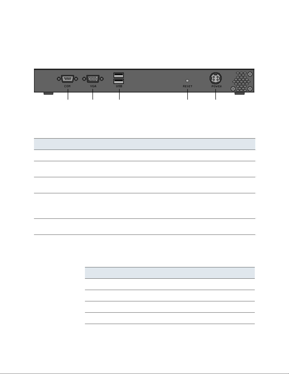
Hardware Specifications
Serial VGA USB Reset Power
Port Port Ports Button Supply
Sourcefire 3D Sensor 500/1000/2000 Specifications
Chassis Rear View
The System Components: Rear View table describes the features on the rear of
the appliance.
System Components: Rear View
Feature Description
Power supply Provides power to the appliance through an AC power source.
Chapter 4
Serial port Allows you to establish a direct workstation-to-appliance connection. This gives
you direct access to all of the appliance’s management services.
VGA port Allows you to attach a monitor to the appliance, as an alternative to using the
serial port to establish a direct workstation-to-appliance connection.
USB ports Allows you to attach a keyboard to the appliance, as an alternative to using the
Reset button Allows you to reboot the appliance without disconnecting it from the power
serial port to establish a direct workstation-to-appliance connection. You also
must use a USB port to restore the appliance to its original factory-delivered
state, using the thumb drive delivered with the appliance.
supply.
The Serial Port Pin Assignments table describes the signal present on the DB-9
connector.
Serial Port Pin Assignments
Pin Signal Description
1 DCD Carrier Detect
2 RD Received Data
3 TD Transmitted Data
4 DTR Data Terminal Ready
Version 4.10.3 Sourcefire 3D Sensor Installation Guide 92

Hardware Specifications
Sourcefire 3D Sensor 500/1000/2000 Specifications
Serial Port Pin Assignments (Continued)
Pin Signal Description
5 GND Ground
6 DSR Data Set Ready
7 RTS Request To Send
8 CTS Clear To Send
9 RI Ring Indicator
Physical and Environmental Parameters
The Physical and Environmental Parameters table describes the physical
attributes and the environmental parameters for the appliance.
Chapter 4
Physical and Environmental Parameters
Parameter Description
Form Factor 1U rack-mounted, or desktop device
Dimensions (D x W x H) 6.7 x 11.8 x 1.25 (in inches)
17 x 30 x 3.2 (in centimeters)
Power Adapter - AC Input 1.6 Ampere maximum at 100-240 Volts, 50/60 Hz
Power Adapter - DC Output 5 Ampere maximum at 12 Volts
Operating Temperature 0°C to 40°C (32°F to 104°F)
Non-Operating Temperature -20°C to +75°C (-4°F to +167°F)
Non-Operating Humidity 5% to 90%, non-condensing at 45°C (113°F)
Acoustic Noise No noise
System Cooling Requirements Designed to operate in an air-conditioned environment
Version 4.10.3 Sourcefire 3D Sensor Installation Guide 93

Hardware Specifications
USB NIC 1 NIC 2Front Panel
Port Controls
Reserved
Sourcefire 3D Sensor 2100/2500/3500/4500 Specifications
Sourcefire 3D Sensor 2100/2500/3500/4500 Specifications
The 3D2100, 3D2500, 3D3500, and 3D4500 models of the 3D Sensor are
delivered on a 1U appliance.
The 3D2500, 3D3500 and 3D4500 Sensors can ship with four-port fiber interfaces
(with bypass capability). Optical connections are LC (Local Connectors).
Supported media is 1000BASE-SX multi-mode optical fiber. Note that the 3D2100,
3D2500, 3D3500, and 3D4500 do not have functional serial ports.
See the following sections for more information about the appliance:
• Chassis Front View on page 94
• Chassis Rear View on page 100
• Physical and Environmental Parameters on page 102
Chassis Front View
Chapter 4
Version 4.10.3 Sourcefire 3D Sensor Installation Guide 94

Hardware Specifications
Sourcefire 3D Sensor 2100/2500/3500/4500 Specifications
The System Components: Front View table describes the features on the front of
the appliance.
System Components: Front View
Feature Description
USB port Allows you to attach a keyboard to the sensor. You also must use a USB
port to restore the sensor to its original factory-delivered state, using the
thumb drive delivered with the appliance.
Chapter 4
NIC 1:
quad-port copper bypass
The NIC 1 slot contains four 10/100/1000 copper Ethernet bypass
interfaces in a paired configuration.
You can use this NIC to passively monitor up to four separate network
segments. You can also use paired interfaces in inline or inline with fail
open mode, which allows you to deploy the sensor as an intrusion
prevention system.
If you want to take advantage of the NIC’s automatic fail-open capability,
which allows traffic to flow even if the sensor fails or loses power, you
must use the two interfaces on the left or the two interfaces on the right
(top and bottom, on the same NIC) as paired interfaces bridging a
network segment. You cannot use any two interfaces, and for Sourcefire
appliances with a second NIC, you cannot use interfaces on different
NICs. You must also use the web interface to configure the interface set
as inline with fail open. Otherwise, you can use any two of the
interfaces on the sensor as an inline pair.
Version 4.10.3 Sourcefire 3D Sensor Installation Guide 95

Hardware Specifications
Sourcefire 3D Sensor 2100/2500/3500/4500 Specifications
System Components: Front View (Continued)
Feature Description
Chapter 4
NIC 2:
no NIC OR
quad-port copper bypass
OR quad-port fiber bypass
Front panel controls Houses five LEDs that display the system’s operating state, as well as
The NIC 2 slot configuration depends on your sensor model:
• The 3D2100 has a slot cover in place of a second NIC.
• The 3D2500 may have no NIC (slot cover) in the NIC 2 slot, or it may
have either a quad-port copper bypass NIC or a quad-port fiber
bypass NIC.
• The 3D3500 and 3D4500 may have either a quad-port copper
bypass NIC or a quad-port fiber NIC in the NIC 2 slot.
The quad-port fiber bypass NIC contains four gigabit interfaces in a
paired configuration, and accepts LC-type (Local Connector) optical
transceivers.
You can use this NIC to passively monitor up to four separate network
segments. You can also use paired interfaces in inline or inline with fail
open mode, which allows you to deploy the sensor as an intrusion
prevention system.
If you want to take advantage of the NIC’s automatic fail-open capability,
which allows traffic to flow even if the sensor fails or loses power, you
must use the two interfaces on the left or the two interfaces on the right
(top and bottom, on the same NIC) as paired interfaces bridging a
network segment. You cannot use any two interfaces, and for Sourcefire
appliances with a second NIC, you cannot use interfaces on different
NICs. You must also use the web interface to configure the interface set
as inline with fail open. Otherwise, you can use any two of the
interfaces on the sensor as an inline pair.
various controls, such as the power button. For more information, see
Front Panel Controls on page 98.
The front of the 3D Sensor includes controls and LED displays for the following:
• Quad-Port Copper Bypass NIC on page 96
• Quad-Port Fiber Bypass NIC on page 97
• Front Panel Controls on page 98
Quad-Port Copper Bypass NIC
Version 4.10.3 Sourcefire 3D Sensor Installation Guide 96

Hardware Specifications
Sourcefire 3D Sensor 2100/2500/3500/4500 Specifications
The Quad-Port Copper Bypass NIC LEDs table describes the LEDs associated
with the network interfaces on the quad-port copper bypass NIC. Note that the
LEDs on NIC1 and NIC2 are reversed.
Quad-Port Copper Bypass NIC LEDs
LED Description
Chapter 4
Activity
NIC1: Left
NIC2: Right
Link
NIC1: Right
NIC2: Left
Indicates traffic activity:
• Blinking green means that packets are being sent or received.
• Solid green means that there is no traffic.
If the activity light is off and the link light is blinking amber, then the inline
interface set for this interface is in bypass mode (it has failed open).
Indicates link status and the speed of the connection.
• An amber light indicates 1Gbps.
• A green light indicates 100 Mbps.
• No light indicates 10 Mbps or no traffic.
If the activity light is off and the link light is blinking amber, then the inline
interface set for this interface is in bypass mode (it has failed open).
Quad-Port Fiber Bypass NIC
Quad-Port Fiber Bypass NIC LEDs
The quad-port fiber bypass card has four LEDs, each of which corresponds to one
of the interfaces. Each interface is labeled with a number (1, 2, 3, and 4,
counterclockwise, starting with the top left). Each LED is also labeled with a
number so that you can easily tell which LED corresponds to which interface.
Version 4.10.3 Sourcefire 3D Sensor Installation Guide 97

Hardware Specifications
ABCDE
FGHI
Sourcefire 3D Sensor 2100/2500/3500/4500 Specifications
The LEDs indicate activity on their corresponding interfaces; a random flash
pattern indicates that packets are being sent or received. If, however, an inline
interface set is in bypass mode (it has failed open), the pair of LEDs (either 1 and
2, or 3 and 4) corresponding to that interface set flash in a regular, alternating
pattern.
Front Panel Controls
The following diagram illustrates the front panel controls and LEDs.
Chapter 4
Front Panel Components
A Power LED F Power button
B System status LED G Non-maskable interrupt button
C Hard drive activity LED H Reset button
D NIC activity LED I ID button
E ID LED
Version 4.10.3 Sourcefire 3D Sensor Installation Guide 98

Hardware Specifications
Sourcefire 3D Sensor 2100/2500/3500/4500 Specifications
The front panel of the chassis houses five LEDs, which display the system’s
operating state. The Front Panel LEDs table describes the LEDs on the front
panel
Front Panel LEDs
LED Description
Power Indicates whether the system has power:
• A green light indicates the power is on.
• No light indicates the power is off.
System status Indicates system status:
• A solid green light indicates the system is operating normally.
• A blinking green light indicates the system is operating in a degraded
condition.
• An amber light indicates the system is in a critical or non-recoverable
condition.
• No light indicates the Power On Self Tests (POST) is underway or the
system has stopped.
Chapter 4
IMPORTANT! The amber status light takes precedence over the green status
light. When the amber LED is on or blinking, the green LED is off.
For more information, see the System Status table on page 100.
Hard drive activity Indicates hard drive activity:
• A blinking green light indicates the fixed disk drive is active.
• An amber light indicates there is a fixed disk drive fault.
• No light indicates no drive activity or the system is powered off.
NIC activity Indicates activity between the system and the network:
• A green light indicates activity.
• No light indicates no activity.
System ID
Helps identify a system installed in a high-density rack with other similar
systems.
• A blue light indicates the ID button is pressed and a blue light appears at
the rear of the appliance.
• No light indicates the ID button is not pressed.
Version 4.10.3 Sourcefire 3D Sensor Installation Guide 99

Hardware Specifications
Mgmt
PS/2 Mouse
PS/2 Keybd
InterfaceConnector
Connector
VGA
USB
Ports
Port
Power Supply
RJ45
Serial Port
Reserved
Sourcefire 3D Sensor 2100/2500/3500/4500 Specifications
The System Status table describes the conditions under which the system status
LED might be lit.
System Status
Condition Description
Critical Any critical or non-recoverable threshold crossing associated with the
following events:
• temperature, voltage, or fan critical threshold crossing
• power subsystem failure
• system inability to power up due to incorrectly installed processors or
processor incompatibility
• critical event logging errors, including System Memory Uncorrectable ECC
error and fatal/uncorrectable bus errors, such as PCI SERR and PERR
Non-Critical A non-critical condition is a threshold crossing associated with the following
events:
• temperature, voltage, or fan non-critical threshold crossing
• chassis intrusion
• Set Fault Indication command from system BIOS; the BIOS may use the
command to indicate additional, non-critical status such as system
memory or CPU configuration changes
Chapter 4
Degraded A degraded condition is associated with the following events:
• one or more processors disabled by Fault Resilient Boot (FRB) or BIOS
• some system memory disabled or mapped out by BIOS
• one of the power supplies unplugged or not functional
TIP! If you observe a degraded condition indication, check your power supply
connections first. Shut down the 3D Sensor, disconnect both power cords,
reconnect the power cords to reseat them, and then restart the 3D Sensor.
Chassis Rear View
Version 4.10.3 Sourcefire 3D Sensor Installation Guide 100
 Loading...