


C4 Synth & Spectrum Intelligent Filter Envelope / Filter Info
Envelope Information from Bob Chidlaw
The$Source$Audio$C4$Synth$pedal$has$two$envelope$followers$available.$They$both$have$the$same$
capabilities,$but$their$control$parameters$may$be$set$differently.$Input$1$or$input$2$may$serve$as$the$
input$signal$to$either.$An$envelope$follower$uses$its$audio$input$signal$to$output$a$representation$of$
how$loud$the$audio$is$at$the$moment.$Louder$signals$get$a$higher$output$level$from$the$envelope$
follower.$
$
Since$the$audio$signal$goes$both$positive$and$negative,$we$first$take$the$absolute$value$of$the$audio;$
negative$values$are$replaced$by$the$same$number,$but$made$positive.$A$certain$amount$of$smoothing$
is$necessary,$because$the$input$signal$will$repeatedly$go$to$zero,$but$at$a$rate$which$we$don't$perceive$
as$a$level$change,$since$it$is$happening$too$fast$for$us$to$hear$like$that.$Deliberately$introducing$a$
slower$than$necessary$smoothing$will$cause$the$output$to$move$more$slowly$than$the$actual$audio$
signal$changes.$Different$smoothing$rates$for$attack$(a$rising$output)$and$decay$(a$falling$output)$
permit$more$control$over$the$final$response.$
$
Whereas$a$typical$synthesizer$has$a$controllable$release$time$on$its$envelopes$(which$begins$when$
one$takes$their$hand$off$a$keyboard$note),$we$have$the$problem$that$the$guitar$sound$is$over$when$a$
note$is$through.$A$synthesizer$oscillator$would$still$be$running,$but$the$pitch$detector$output$tends$to$
lose$it$as$a$note$is$dying$away,$so$the$synth$oscillator$is$also$not$reliably$available$after$note$end.$So$
our$final$release$times$are$always$quite$short.$
$
$
We$also$offer$ADSR$type$envelopes$(attack$–$decay$–$sustain$–$release).$The$attack$segment$begins$
when$an$attack$threshold$level$is$exceeded.$When$the$envelope$level$gets$to$1.0$(full$scale$ON),$the$
decay$segment$takes$over,$dropping$until$the$sustain$level$is$reached.$When$the$input$gets$below$a$
release$threshold,$we$go$into$a$(fast,$as$always)$release$segment.$These$threshold$levels$are$fixed.$
One$more$reason$to$do$the$Input$Gain$Calibration$procedure,$to$make$sure$your$guitar$signal$is$in$the$
proper$range,$for$the$fixed$thresholds.$
$
All$of$these$possible$envelope$controls$are$not$brought$out$to$the$user$interface.$This$is$partly$due$to$
trying$to$save$bits$in$the$preset$data$(and$if$you$had$asked$me$50$years$ago$whether$saving$bits$
would$still$be$a$thing$in$2019,$I$would$have$laughed),$and$also$to$keep$the$complexity$down.$
Reasonable$people$may$disagree$that$boiling$down$a$lot$of$controls$into$only$a$few,$with$a$selection$
of$envelope$types,$is$really$simpler.$But$that's$the$way$it$is.$
The$Envelope$Type$definitions:!
!
SA248 C4 Synth User Guide 1

$
The$Speed$control$goes$from$0.0$to$1.0,$for$both$Attack$and$Decay$times.$This$is$translated$to$the$
following$range$of$what$are$called$"time$constants".$(After$one$time$constant,$a$decaying$signal$has$
dropped$to$36.8%$(or$-8.7$dB) from$its$starting$value.)$
!
$
$
The$Fast-Attack$number$controls$exactly$how$fast$the$initial$attack$can$rise.$1.0$is$instantaneous;$0.5$
is$the$fastest$used.$Most$are$considerably$slower.$The$ADSR$envelopes$do$not$use$this$control.$
$
Sustain$is$the$ADSR$sustain$level.$Most$are$0.0,$with$two$at$0.2.
More Information on the Filter Processors
Theory of operation: Internally, the Spectrum contains two independent processing blocks that
perform the filtering operations. Each block has three sections, each capable of a variety of twopole filters. These are then connected in series or parallel, with small mixers to sum as the case
$
SA248 C4 Synth User Guide 2

may be. This gives us a large variety of frequency response shapes. While the sound is, of
course, determined from its frequency response, that doesn't mean it's easy to tell what
something will sound like just from looking at the frequency response. Not even for us. The
Frequency control for the filter moves the entire frequency response up and down in frequency,
with all three filter sections moving together. When Modulation is applied, the three sections
may move together or independently, with some moving up while others move down, or they
may move in the same direction, but a different amount. Unless independent motion is
specified, you may assume the entire frequency response moves as a unit when modulated,
without changing shape.
Note: It is possible to combine any of the filter types in parallel with the same envelope source.
This makes essentially for endless filter types.
Filter Types for C4 Synth & Spectrum Intelligent Filter
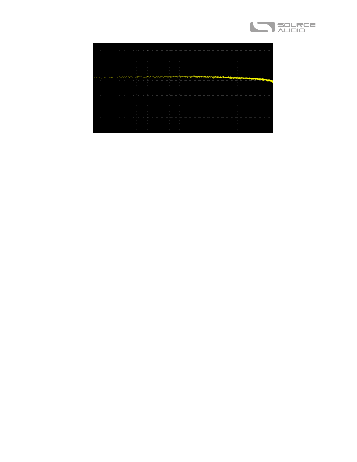
3 Pole Parallel Low Pass
6 Pole Low Pass
Response drops at 36 dB/octave.
SA248 C4 Synth User Guide 3

2 Pole Low Pass (Low Q)
A very classic filter shape. Above what is termed the cut-off frequency, the response drops, at 12
dB/octave. If the Q control is turned up at least some, there will be a resonant peak at the cut-off
frequency. Higher Q's produce higher peaks.
2 Pole Low Mass (Mid Q)
2 Pole Low Pass (High Q)
SA248 C4 Synth User Guide 4

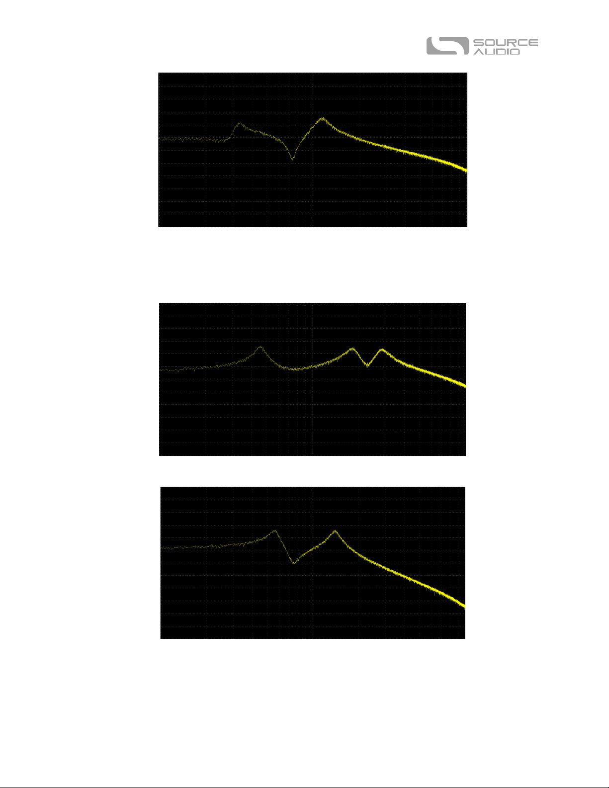
Notch, Low Pass, Peak
A notch, a peak, and then a Low-Pass without any resonant peak. (The name implies they are in a
different order, but that is an error.) The notch is fixed at wide, and ignores the Q control. Q
controls the width of the peak. There will be a little phasery-ness to any response with a notch in it.
Notch, Notch, Low Pass
Two notches and then a Low-Pass.
Peak, Notch, Low Pass
A peak, followed by a notch, and then a Low-Pass. If a peak is present in a filter, and if Q is set to the
minimum, the peak becomes so wide that it tends to wash out any other structure, and will sound
less interesting.
SA248 C4 Synth User Guide 5
Low Pass, Peak, Peak
Two pole Low-Pass has two Band-Passes summed at higher frequencies. Independent motion.
2 Parallel Low Pass
SA248 C4 Synth User Guide 6

4 Pole Low Pass
Low Pass, Peak
A Band-Pass is summed with a Low-Pass. The frequency of the Band-Pass is above the cut-off
frequency of the Low-Pass. The Band-Pass and the Low-Pass filters move together.
4 Pole Low Pass, Peak
Band-Pass summed with the 4 Pole Low-Pass. Independent motion.
SA248 C4 Synth User Guide 7

Peak, 4 Pole Low Pass
Another Band-Pass summed with 4 Pole Low-Pass, but here the Band-Pass frequency is below the
cut-off frequency of the Low-Pass. Independent motion.
Band Pass
Only a range of frequencies gets through. Higher Q's produce a narrower response.
Peak
The original input signal is summed with a Band-Pass. It looks something like a midrange control
doing boost.
SA248 C4 Synth User Guide 8

Triple Peak 1
Three Band-Passes summed. Independent motion. These triple Band-Passes can do some vocal
sounding responses.
Triple Peak 2
Three Band-Passes summed. Independent motion.
Triple Peak 3
Three Band-Passes summed. Independent motion.
SA248 C4 Synth User Guide 9

Triple Peak 4
Three Band-Passes summed. Independent motion.
Peak, Notch, Peak
A flat frequency response has a peak, then a notch, and then another peak.
Notch, Peak, Notch
A flat frequency response has a notch, then a peak, and then another notch.
SA248 C4 Synth User Guide 10

2-Stage Phaser
3-Stage Phaser
1-Stage Phaser
SA248 C4 Synth User Guide 11

High-Pass
Frequencies below the cut-off frequency are rolled-off, at a rate of 6 dB/octave. There is a resonant
peak at the cut-off frequency.
High Pass, Peak
A Band-Pass is summed with a High-Pass, above the cut-off frequency.
Crybaby
An accurate model of the classic cry-baby wah pedal. The Q control has no effect.
SA248 C4 Synth User Guide 12

Band pass 2
Only a range of frequencies gets through. Higher Q's produce a narrower response.
Double Peak
Input is summed with two Band-Passes. Independent motion.
6 Pole All Pass
An All-Pass filter is one with a flat amplitude response, but where the phase is shifted, with higher
frequencies getting more phase shift than lower frequencies. When modulated with a sine LFO of
around 6 Hz, a strange vibrato may be obtained. This is the only way to add vibrato to the input
signal.
SA248 C4 Synth User Guide 13
SA248 C4 Synth User Guide 14
 Loading...