

Page 1

Soundwin
GSM
GATEWAY
User Manual
Page 2

Version: 1.01 –
Table of Contents
TABLE OF CONTENTS 2
PREFACES 5
0.1 ABOUT THIS MANUAL 5
0.2 COPYRIGHT DECLARATIONS 5
0.3 TRADEMARKS 5
0.4 SAFETY INSTRUCTIONS 5
0.5 WARRANTY 6
INTRODUCE 7
1.1 OVERVIEW 7
1.2 ACRONYMS TABLE 7
1.3 INTRODUCTION 8
1.4 FRONT PANEL LED INDICATORS & REAR PANELS 9
1.4.1 OUTLOOK OF G100& V100 9
1.4.2 FRONT PANEL LED AND CONTAINER DESCRIPTIONS 9
1.4.3 REAR PANEL DESCRIPTIONS 10
1.5 FEATURES AND SPECIFICATIONS 12
INSTALLATION AND SETUP 14
2
Page 3

2.1 PACKAGE CONTENT 14
2.2 INSTALLATION 15
2.3 SETUP 17
2.3.1 FACTORY DEFAULT SETTING 17
2.3.2 SETTING UP NETWORK 14
2.3.3
TELNET 21
2.3.4 WEB USER INTERFACE 23
GSM SETUP 20
3.1 GSM SETUP 20
3.1.1 GSM PARAMETER 21
3.1.2 PSTN DIALPLAN 21
3.1.3 GSM DIALPLAN 22
3.1.4 SMS SETTING 22
ADVANCED SETUP 23
4.1 NETWORK CONFIGURATION 30
4.1.1 WAN PORT TYPE SETUP 30
4.1.2 DYNAMIC DNS 32
4.1.3 NETWORK MANAGEMENT 33
4.2 VOIP SETUP 34
4.2.1 H.323 SETUP 34
4.2.2 SIP SETUP 39
4.2.3 DIRECT CALL (PEER TO PEER) SETUP 44
4.2.4 OTHER VOIP SETTING 46
4.3 SYSTEM ADMINISTRATOR 48
4.3.1 SAVE CONFIGURATION AND REBOOT 49
4.3.2 ACCESS CONTROL 49
4.3.3 SET TO DEFAULT CONFIGURATION 50
4.3.4 SYSTEM INFORMATION DISPLAY FUNCTION 50
4.3.5 SNTP SETTING FUNCTION 50
4.3.6 CAPTURE PACKETS FUNCTION 51
4.4 FIRMWARE UPGRADE GUIDE 52
3
Page 4

APPENDIX 55
A FAQ LIST 55
B SIP SETTING VOIPBUSTER 56
C SIP SPEEDS CALL 57
APPLICATIONS 53
D
4
Page 5

PREFACES
0.1 About This Manual
This manual is designed to assist users in using GSM Gateway. Information in this
document has been carefully checked for accuracy; however, no guarantee is given as to
the correctness of the contents. The information contained in this document is subject
to change without notice.
0.2 Copyright Declarations
Copyright 2007 Telephony Corporation. All rights reserved. This publication contains
information that is protected by copyright. No part may be reproduced, transmitted,
transcribed, stored in a retrieval system, or translated into any language without written
permission from the copyright holders.
0.3 Trademarks
Products and Corporate names appearing in this manual may or not be registered
trademarks or copyrights of their respective companies, and are used only for iden
tification or explanation and to the owners’ benefit, without to infringe.
0.4 Safety Instructions
The most careful attention has been devoted to quality standards in the manufacture
of the Gateway. Safety is a major factor in the design of every set. But, safety is your
responsibility too.
Use only the required power voltage. Power Input: AC 100-240V, 50-60Hz
To reduce the risk of electric shock, do not disassemble this product. Opening or
removing covers may expose the Gateway to hazardous voltages. Incorrect
reassembly can cause electric shock when this product is subsequently used.
Never push objects of any kind into the equipment through housing slots since they
may touch hazardous voltage points or short out parts those could result in a risk of
electric shock. Never spill liquid of any kind on the product. If liquid is spilled, please
refer to the proper service personnel.
Use only Unshielded Twisted Pair (UTP) Category 5 Ethernet cable to RJ-45 port of
5
Page 6

the Gateway.
0.5 Warranty
We warrant to the original end user (purchaser) that the GSM gateway will be free from
any defects in workmanship or materials for a period of one (1) years from the date of
purchase from the dealer. Please keep your purchase receipt in a safe place as it serves
as proof of date of purchase. During the warranty period, and upon proof of purchase,
should the product have indications of failure due to faulty workmanship and/or
materials, we will, at our discretion, repair or replace the defective products or
components, without charge for either parts or labor, to whatever extent we deem
necessary to re-store the product to proper operating condition. Any replacement will
consist of a new or re-manufactured functionally equivalent product of equal value, and
will be offered solely at our discretion. This warranty will not apply if the product is
modified, misused, tampered with, damaged by an act of God, or subjected to abnormal
working conditions. The warranty does not cover the bundled or licensed software of
other vendors. Defects which do not significantly affect the usability of the product will
not be covered by the warranty. We reserve the right to revise the manual and online
documentation and to make changes from time to time in the contents hereof without
obligation to notify any person of such revision or changes.
Note
Repair or replacement, as provided under this warranty, is the exclusive remedy of
the purchaser. This warranty is in lieu of all other warranties, express or implied,
including any implied warranty of merchantability or fitness for a particular use or
purpose. We shall in no event be held liable for indirect or consequential damages of
any kind of character to the purchaser.
To obtain the services of this warranty, contact us for your Return Material
Authorization number (RMA). Products must be returned Postage Prepaid. It is
recommended that the unit be insured when shipped. Any returned products without
proof of purchase or those with an out-dated warranty will be repaired or replaced
and the customer will be billed for parts and labor. All repaired or replaced products
will be shipped by us to the corresponding return address, Postage Paid. This
warranty gives you specific legal rights, and you may also have other rights that vary
from country to country.
6
Page 7

Introduce
GSM Gateway is designed for lowering company telephone bill in calling mobile
numbers. This document describes the usage of GSM Gateway.
1.1 Overview
G100
The G100 Quad-Band GSM gateway has been designed not only for Voice transmission
between your PBX and GSM networks, but also for Data, SMS Transmit between your PC
(LAN) and GSM networks.
V100
- G100 with VoIP
The V100 Quad-Band GSM over VoIP gateway has been designed for user to make calls
and receive calls from a cellular phone via the internet using VoIP (SIP/H.323).
1.2 Acronyms Table
7
Page 8

Acronym: Full Name: Acronym: Full Name:
ADC Analog to Digital Converter CODEC Coder / Decoder
DAC Digital to Analog Converter DC Direct Current
DDNS Dynamic Domain Name System DHCP Dynamic Host Configuration
Protocol
DMZ Demilitarized Zone DNS Domain Name System
DTMF Dual Tone Multi Frequency FXS Foreign Exchange Station
GMT Greenwich Mean Time GSM Global System for Mobile
Communications
IP Internet Protocol LAN Local Area Network
WAN Wide Area Network MAC Media Access Control
NTP Network Time Protocol RTP Real-Time Transport Protocol
RTCP Real-Time Transport Control
Protocol (also known as RTP
control protocol)
SLIC Subscriber Line Interface
Circuit
URI Uniform Resource Identifier TCP Transmission Control Protocol
UDP User Datagram Protocol VoIP Voice Over Internet Protocol
NAT Network Address
Translation
SIP Session Initiation Protocol
STUN Simple Traversal of UDP
through NATs
1.3 Compare Table
Model Compare Table
Model FXS Port PSTN WAN Port VoIP
G100
V100
* manufacture by order (lead time : 60 days)
8
1 1 1
1 1 1 v
Page 9

1.4 Front Panel LED Indicators & Rear Panels
1.4.1 Outlook of G100& V100
Front
* The outlook of G100 & V100 are the same
Rear
1.4.2 Front Panel LED and Container Descriptions
9
Page 10

LED State Description
Power ON GSM Gateway is Power On
OFF GSM Gateway is Power Off
WAN ON Network connection established
Flashing Data traffic on cable network
OFF Waiting for network connection
Line ON Line is busy
Flashing Ring Indication
OFF Line is not enabled
Phone ON Telephone Set is Off-Hook
Flashing Ring Indication
OFF Telephone Set is On-Hook
GSM Flashing GSM Network is found and working properly
ON The GSM call is running.
OFF GSM Network is failed.
SMS ON Short message waiting Indicator
Flashing Sending short message
1.4.3 Rear Panel Descriptions
10
Page 11
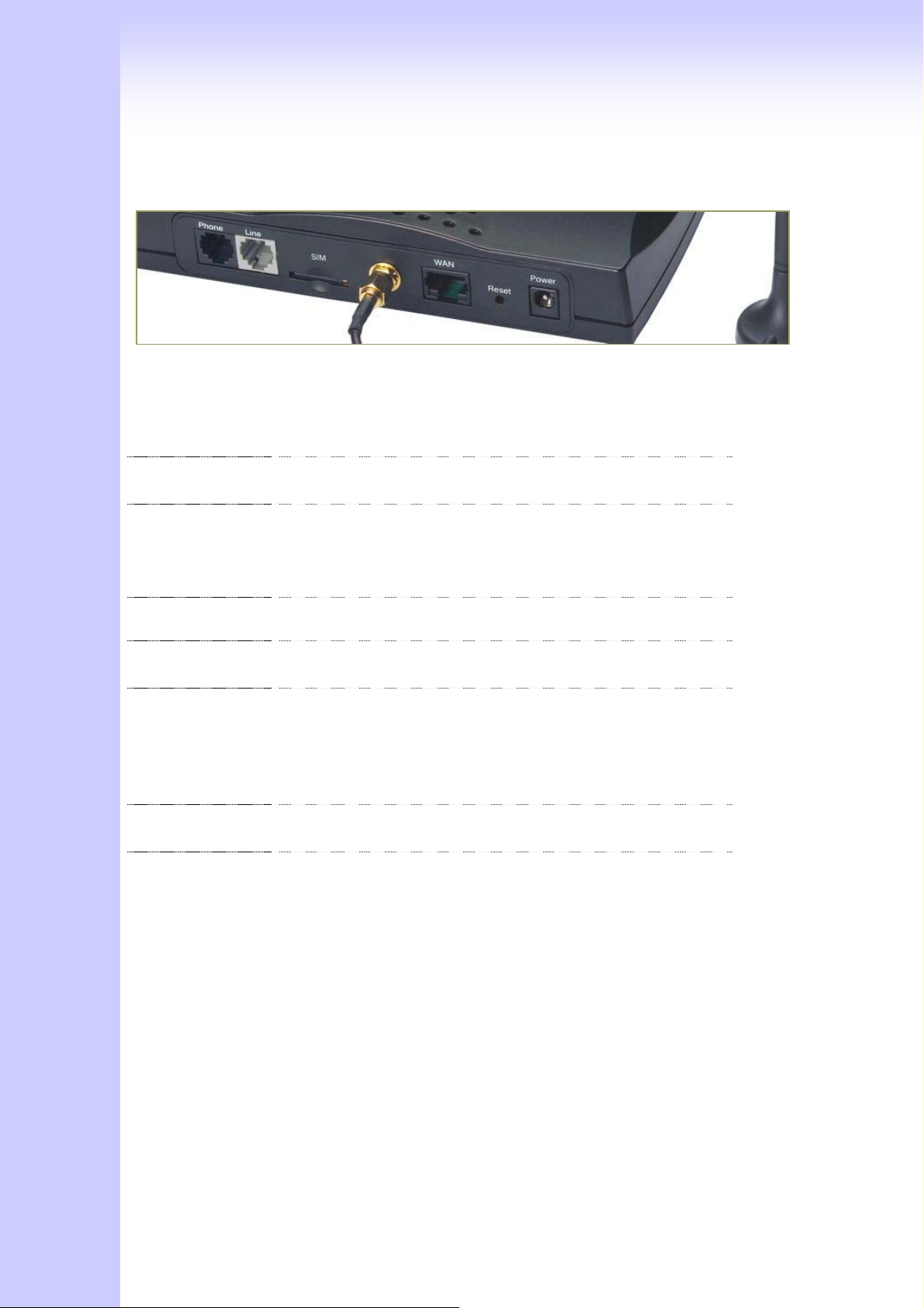
Port Description
Phone Phone port can be connected to analog telephone sets or
Trunk Line of PBX
Line Can be Connected to PBX or CO line with RJ-11 analog line.
PSTN not FXO port, can’t connect PSTN to VoIP,. When PSTN
call comes, it will transfer to FXS port, let FXS can pick up
call from VoIP or PSTN.
SIM The port which you can Insert SIM Card
Antenna
Connector
WAN Connect to the network with an Ethernet cable. This port
Reset Push this button until 3 seconds, and ATA will be set to
Power A power supply cable is inserted
Connect the antenna to the gateway.
allows your ATA to be connected to an Internet Access
device, e.g. router, cable modem, ADSL modem, through a
networking cable with RJ-45 connectors used on 10BaseT
and 100BaseTX networks.
factory default configuration.
11
Page 12

1.5 Features & General Specifications
G100 & V100 Common Features and Specifications
Features
‧2-wire, FXS interface (for analog phone or PBX CO line) and PSTN Line
‧SMS Server for SMS sending & receiving
‧Dialed number restriction, evaluation and modification
‧Easy & comfortable maintenance, configuration and upgrade
General Specification
‧ Compatible with European, US, Brazil and Japan GSM networks (850/900/1800/1900
MHz)
‧SIM: supports SIM card (3V)
‧1 WAN port, 1 FXS port, 1 PSTN port
‧Radio interface: Quad-Band EGSM 900/1800/850/1900
‧AC power: AC100V-240V, DC12V/1.5A,50/60 Hz
‧Temperature: 0°C ~ 40°C (Operation)
‧Humidity: up to 90% non-condensing
‧Emission: FCC Part 15 Class B, CE Mark
‧Dimension: 170 x 100 x 35 mm
‧Weight: 200g
Configuration & Management
‧Web-based Graphical User Interface
‧Remote management over the IP Network
‧FTP firmware upgrade
‧Backup and Restore Configuration file
‧Syslog client support
‧Auto-Provision
V100 only (with VoIP gateway features)
12
Page 13

Additional Features
‧Calls from cellular over VoIP
IP Specifications
‧H.323 v2/v3/v4 and SIP (RFC 3261), SDP (RFC 2327), Symmetric RTP, STUN (RFC3489),
ENUM (RFC 2916), RTP Payload for DTMF Digits (RFC2833), Outbound Proxy Support.
‧Voice Codec: G.711(A-law /μ-law), G.729 AB, G.723 (6.3 Kbps / 5.3Kbps)
‧WAN: Support PPPoE client, DHCP client, Fix IP Address, DDNS client
‧Support MWI (Message Waiting Indicator) by SIP Notify.
Call Features
‧Voice channels status display
‧Direct Dialing Mode : peer to peer call (support IP Address Call or Domain Name Call)
‧Register Call Mode : register to SIP Proxy Server or H.323 Gatekeeper
‧Adjustable volume : - 9 db ~ 9 db
‧Silence Compression / VAD
‧Auto Dial for speed
‧Dynamic Jitter Buffer
‧Hot-Line and Warm-Line Support
13
Page 14

Installation and Setup
2.1 Package Content
Please check enclosed product and its accessories before installation. (Refer to the
item number). These contents are from pre-released product. The contents for the final
product might change a little bit.
Appurtenances:
14
Page 15
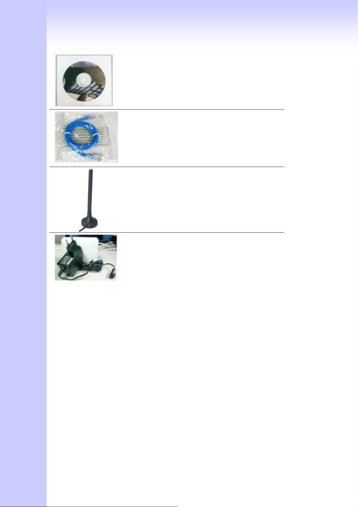
CD ROM
CD Include in all product user manual and
datasheet.
RJ-45 cable
Internet cable RJ-45 connect to NIC/Gateway/Router
Antenna
This Antenna frequency is 900MHz/1800,1900Mhz
for automobile.
Power supply
Power Supply,input:100-240V output:+12V
(Europe/UK/US)
2.2 Installation
1. Install Gateway
1 Connect the 12V DC IN to the power outlet with power adaptor.
2 Connect Line to PSTN Line.
3 Connect Phone port to a telephone jack with the RJ-11 analog cable (Phone / PBX
Trunk Line.)
4 Connect the antenna to the Antenna Connector.
5 Insert SIM card to the gateway
6 Poweron
Warning: to avoid the product damaged, please insert SIM card before
15
Page 16
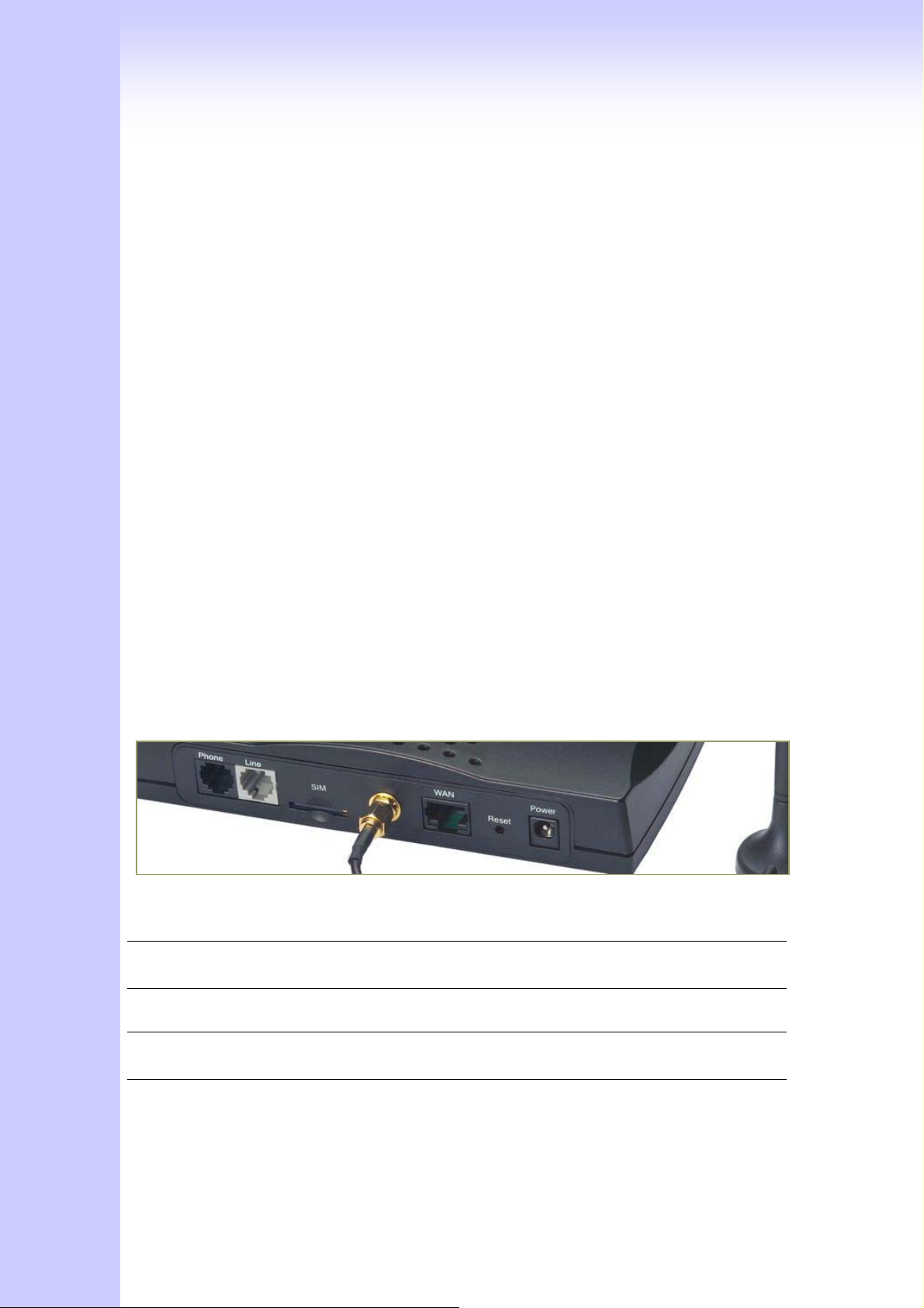
power-on, and power-off first if it is necessary to take SIM card out of the
product.
2. Setting up the network environment for configuration
- To be able to enter the configuration system via web or telnet.
1. Connect the Ethernet cable (with RJ-45 connector) to WAN port.
GSM Gateway ----- RJ45 directly link ----- PC
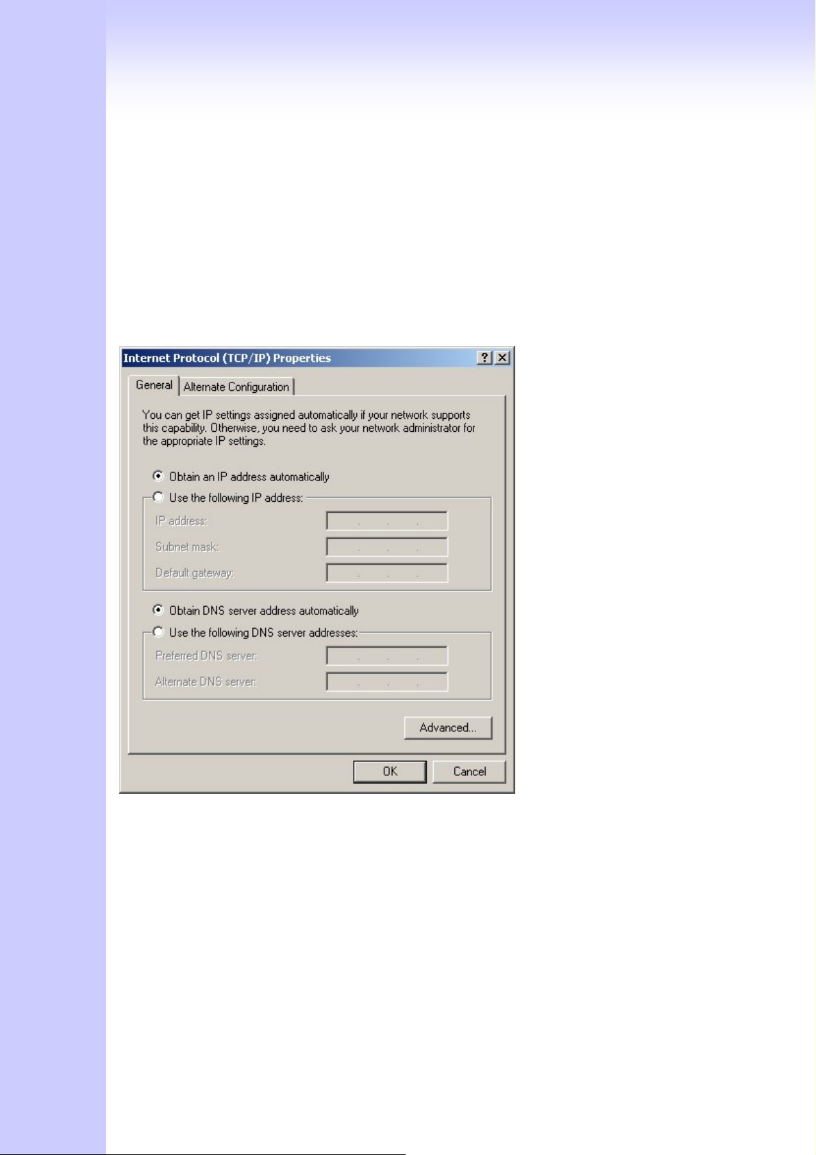
2. Change the IP address to 192.168.1.2(2~254 is ok)
3. Change the subnet mask to 255.255.255.0
4. Change the gateway and the preferred DNS server to 192.168.1.1
IP configurations above please refer to page 15
3. After Network Configuration is done.
Connecting to an External Ethernet Hub or Switch:
1 Connect the Ethernet cable (with RJ-45 connector) to WAN port.
2 Connect the other end of the Ethernet cable to DSL/Cable modem or the external
Ethernet hub or switch.
[Notice:
Please follow step.2 to enter gateway, the values are special premade settings]
If It's not able to access the GSM Gateway via Internet
Port Description
Phone FXS port can be connected to analog telephone sets or
Trunk Line of PBX.
Line Line is used to connect to a PSTN line of carrier.
SIM After Inserting SIM card ,the gateway is able to work as
a mobile phone.
Antenna Connector Connect the antenna to the connector
16
Page 17

WAN For Setting Connect directly to your PC with RJ 45
For WAN Connect to the network with an Ethernet cable.
This port allows your GW to be connected to an Internet
Access device, e.g. router, cable modem, ADSL modem,
through a networking cable with RJ-45 connectors used
on 10BaseT and 100BaseTX networks.
RES Push this button until 3 seconds, and GW will be set to
factory default configuration.
AC power(DC in 12V) A power supply cable is inserted
The hardware installation is now complete. The following sections will guide you
through setting up your management PC and connecting to the Web User Interface.
2.3 Setup
There are 2 way to setting gateway - Web User Interface, Telnet
2.3.1 Factory Default setting
WAN Port IP address : 192.168.1.1
Default login authentication username : admin, password : admin
V100 only (VoIP feature)
VoIP Number Port_1~Port_2 number:100,200
VoIP default setting was H.323 signal protocol, Direct Mode, Fast-Start and G.723
codec.
2.3.2 Setting Up Network
Checking the Network IP Configuration
The following explains how to setup the Transmission Control Protocol/Internet
Protocol (TCP/IP) in Windows 2000/XP. For more detailed information on TCP/IP setup,
17
Page 18
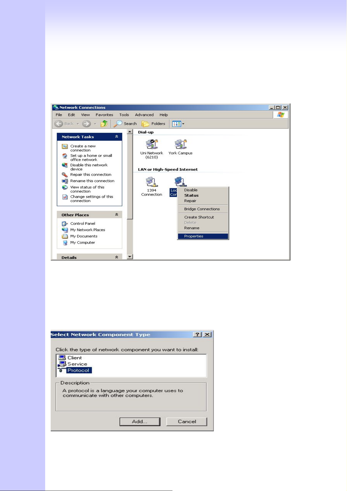
refer to the Windows 2000/XP help files. For other operating systems refer to the user
manuals.
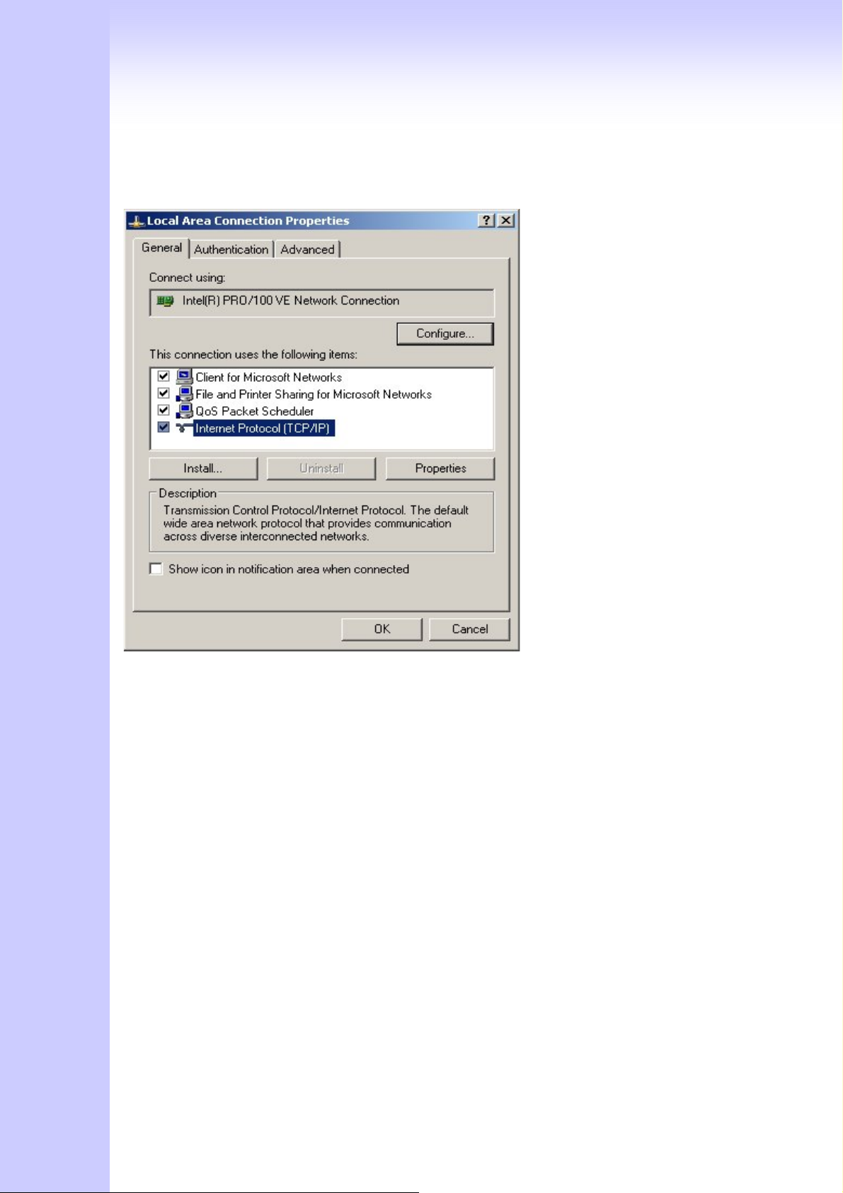
1. On the desktop, Please enter start -> control panel -> network setting.” Click
Properties. The Network screen will open.
(Your particular system will be different from the screen shown here.)
Check that you have an Ethernet network card installed. If not, refer to the card
manufacturer’s documentation and install the card and drivers.
If your card is installed,
1. Click the Add button. The Select Network Component Type dialog box will open. The
box will show four options:
Client, Adapter, Protocol, and Service.
18
Page 19
2. Select Protocol and click the Add button. The Select Network Protocol dialog box will
open.
3. Select Microsoft in the left scrolling window then selects TCP/IP in the right, and click
OK.”. You will be returned to the Network dialog box.
Configuring the TCP/IP Protocol
1. On the Network dialog box Configuration card, select TCP/IP and then click
Properties.” The TCP/IP Properties dialog box will open.
2. On the IP Address tab, Change the IP address to 192.168.1.2(2~254 is ok)
the subnet mask to 255.255.255.0, the gateway and the preferred DNS server to
192.168.1.1
5. click OK. A dialog box will pop up asking you to restart the PC. Click Yes”.
Checking TCP/IP settings
1. After completing the previous steps, click Start -> Run -> and type ipconfig /all. The
IP Configuration window will open. If the PC does not show an IP address in the
19
Page 20
192.168.1.2 to 192.168.1.254 range, click the ipconfig /release button to release the
current configuration. Wait a few seconds and click “ipconfig/renew” to get a new IP
configuration from the router.
2. If the IP configuration is correct, you will be able to use the PING diagnostic utility
built into Microsoft Windows to ping the router. Click Start -> Programs -> MS-DOS
Prompt. A command mode window will open.Type “ping 192.168.1.1” (default IP of the
router) to check the network connectivity. If both hardware and software are correct,
your computer will receive a response from the router as shown on the next page. If not,
verify that the Ethernet cable is connected to the router properly and the Ethernet port
LED on the front panel is lit.
20
Page 21
2.3.2 Telnet
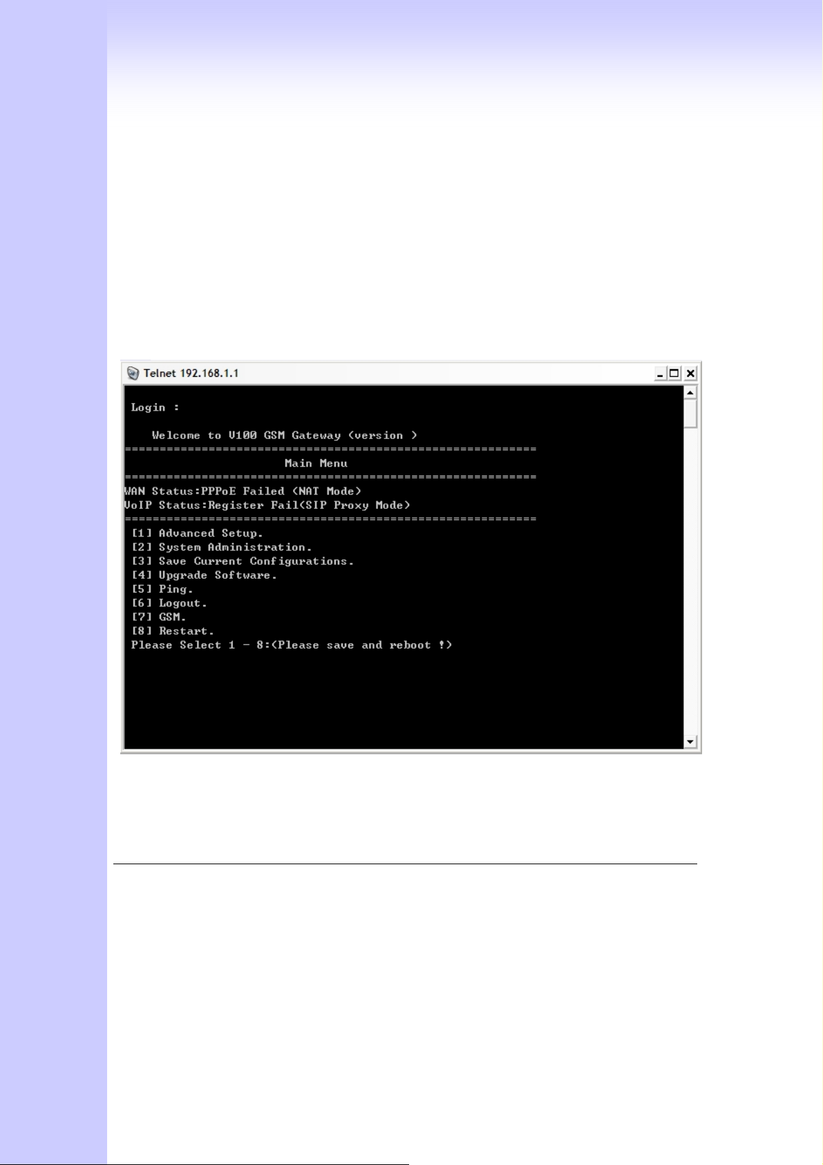
Connect WAN port to Internet or PC and gateway at the same subnet. you can use
telnet remote to configure your gateway.
1. Connect Gateway online (Wan)
2. Remote Gateway by Telnet. If telnet successful, you will see Login display.
(For Example: telnet 192.168.1.1)
3. Input Password (Gateway Access password, Default: admin), If login successful, you
will enter the welcome display.
4. Gateway Telnet Setting Table, Use 1~9 a~z select setting, “ESC” is back setting.
Item Setting Option
Main [1] Advanced Setup.
[2] System Administration.
[3] Save Current Configurations.
[4] Upgrade Software.
[5] Ping.
[6] Logout.
[7] GSM
[8] Restart.
21
Page 22

[1]Advanced Setup 1.WAN Setting
2.DNS/Dynamic DNS Setting
3.Network Management
4.VoIP Basic
5.Dialing Plan
6.VoIP Advance Setting
7.Hot Line Setting
8.Port Status
9.Busy Tone Learning
a. Show DNS mapping
[1]Advanced Setup
……1.WAN Setting
1.Change WAN Type to DHCP
2.Change WAN Type to Fixed IP
3.Change PPPoE Username
4.Change PPPoE Password
[1]Advanced Setup
……2.NS/Dynamic DNS
Setting
1.Change DDNS username
2.Change DDNS password
3.Change DDNS domain name
4.Change DNS server IP
5.Enable/Disable Get DNS Server IP
6.Change DNS server IP
[1]Advanced Setup
…3Network Management
1.Change web server port
2.Change telnet server port
[1]Advanced Setup
……4.VoIP Basic
1.Change VoIP Protocol to H.323
2.Change Port Number/Account/Password
3.Enable/Disable Public account
4.SIP hunting setting
5.Change SIP Proxy Server IP Address/DNS
6.Use net2phone
7.Change Register Interval(seconds)
8.Enable/Disable SIP authentication
9.NAT Pass Method
a. STUN Server address
b. SIP realm
c. Outbound Proxy Server address
d.Change SIP Local Port
[1]Advanced Setup
……5.Dialing Plan
1.Add Outbound Direct Call
2.Delete Outbound Direct Call
3.Add Inbound Direct Call
4.Delete Inbound Direct Call
[1]Advanced Setup
……6.VoIP Advance
Setting
(1)Sip Advance
1.Set DTMF Relay Mode
2.Change FAX Mode
3.Enable/Disable VoIP Encryption
22
Page 23

4.VoIP Encryption Port Setting
(2)Telephone Advance
1.VAD(Silence Compression)On/Off
2.Change Codec
3.Enable/Disable UK PSTN Tone Detection?
4.Enable/Disable Dial Complete Tone
5.Dial Termination Key Setting
6.FXS Parameters Setting
1.Change FXS Impedance
2.Change Phone In Volume
3.Change Phone Out Volume
4.Flash Detection
5.Ring Frequency
6.FXS Battery reversal generation
(3)Network Advance
1.Disable Smart QOS
2.Bandwidth Control
3.G.723 Bandwidth
4.G.729 Bandwidth
5.Set IP TOS
[1]Advanced Setup
……7.Hot Line Setting
[2] System Administration. 1.Save Configuration
1.Change Port1 Hot Line Number
2.Change Port2 Hot Line Number…….(To your own port)
2.Access Control
3.Set to Default
4.System Information
5.NTP Setting
6.Syslog Setting
2.3.4 Web User Interface
Connecting to the Web Configuration via a Web Browser
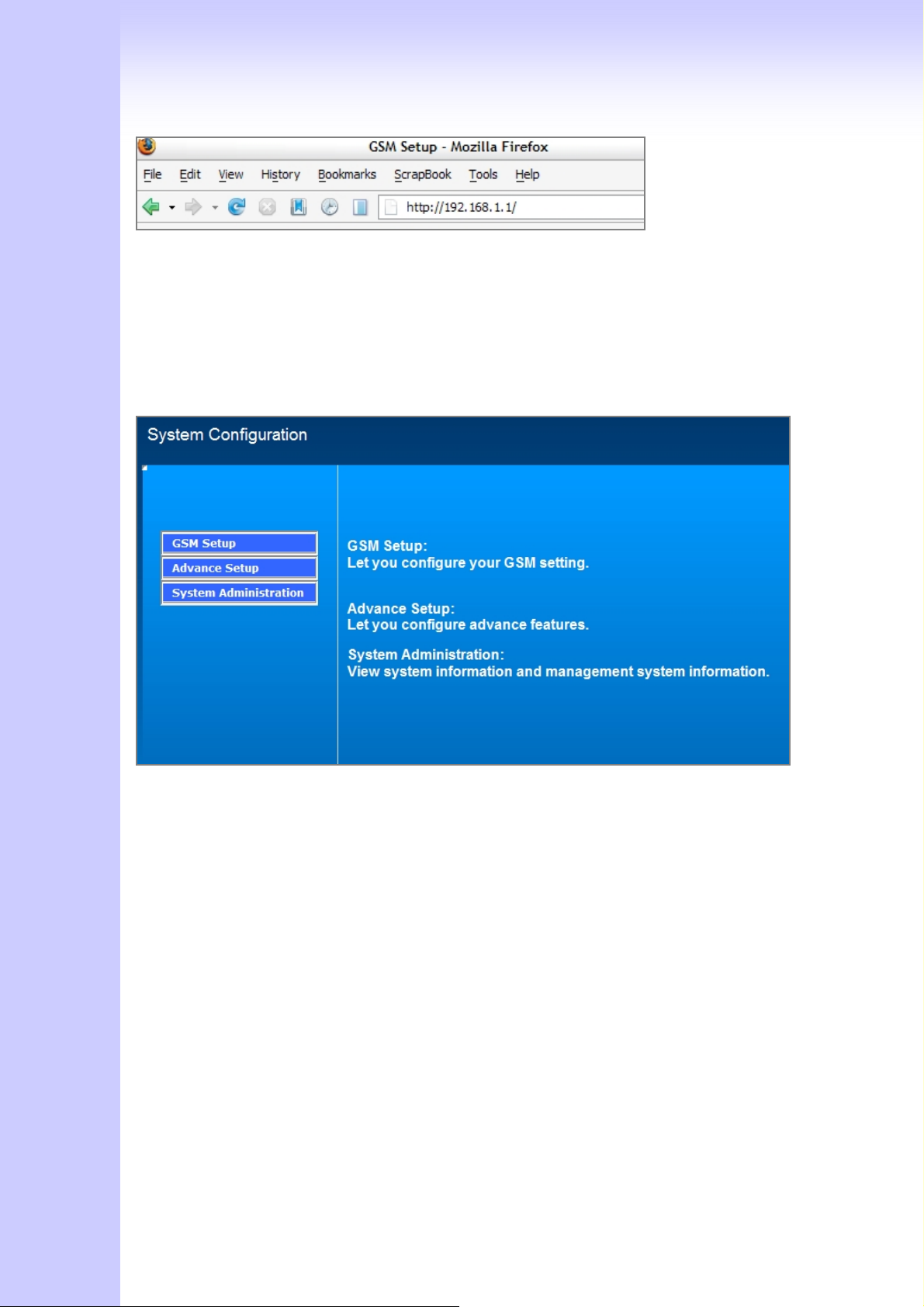
1. Launch the Web browser (IE or Firefox). Enter http://192.168.1.1 into the browser
Address window and press the Enter Key
23
Page 24
2. An authentication dialog box will open.
3. If this is a first time setup of the router, type “admin” as the User Name and the
Password field as “admin”. Click OK.(Default username/Password is “admin”)
4. The Web Configuration Setup Main Menu will open. On the main page [GSM Setup],
[Advanced Setup] and [System Information] were displayed.
GSM SETUP
3.1 GSM SETUP
24
Page 25
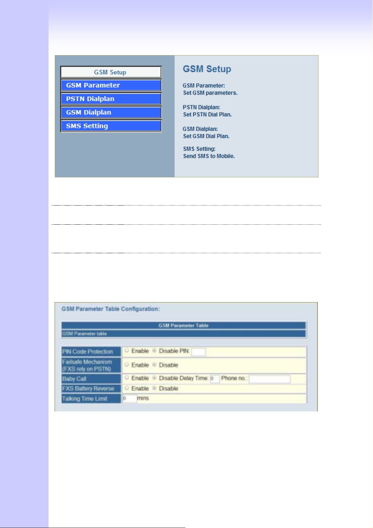
GSM Parameter GSM Parameter allows you to modify the option of GSM
network.
PSTN Dailplan Users could apply any dial policy by setting Dial Plan to route
the Calls to PSTN
GSM Dialplan Users could apply any dial policy by setting Dial Plan to route
the Calls to GSM Network.
SMS setting The Option is used to send short message to mobile phones
3.1.1 GSM Parameter
PIN Code Protection: Enable PIN Code protection.
Failsafe Mechanism: If enable, when GSM Network is failed or GSM Gateway is out of
25
Page 26
the GSM service range. ALL the calls from FXS will route to PSTN port.
Baby Call:
automatically.
Follow ME:
automatically.
FXS Battery Reverse: Enable battery reverse generator.
Talking Time limit: The period of talking time, when the time ends, a beep sound
will come out as a warning sound.
When the calls come to FXS port, it will call hot line number to GSM
When the calls come to PSTN, it will call hot line number to GSM
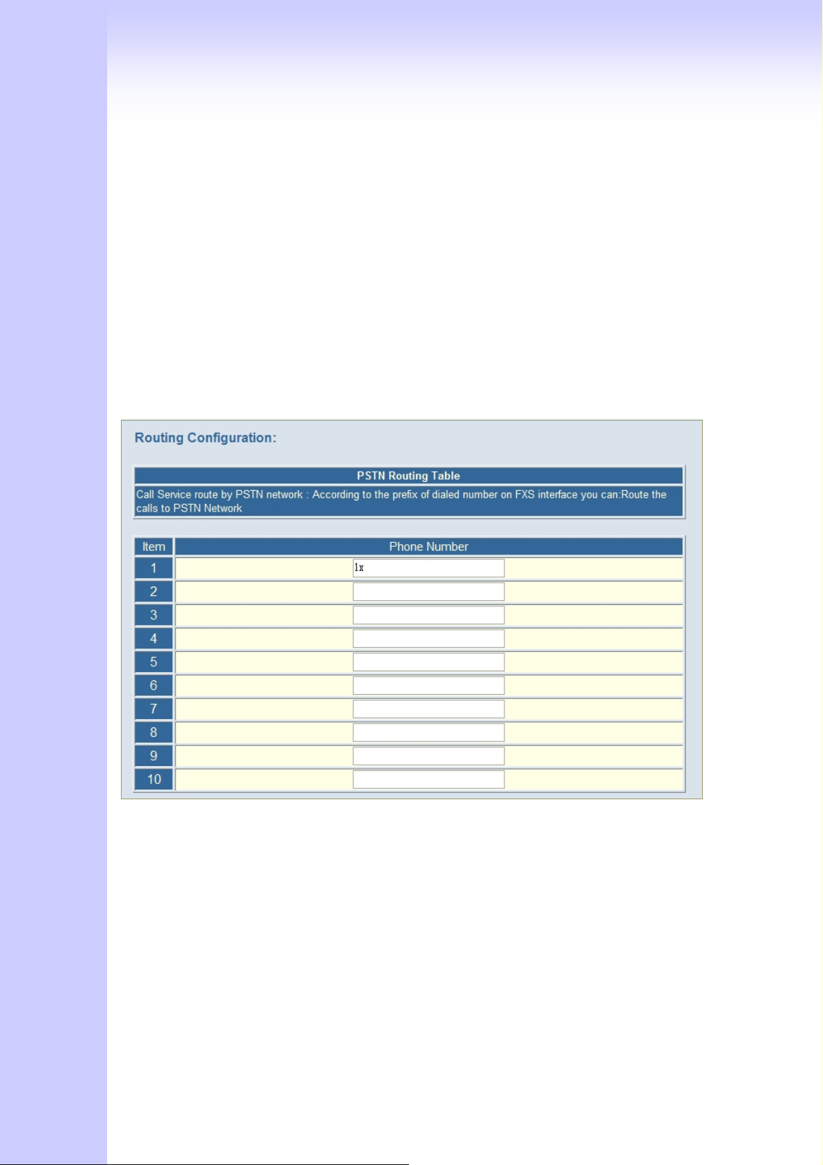
3.1.2 PSTN Dialplan
PSTN Route Numbers: The numbers which are filled in the form will go through the PSTN
line unconditionally. You can use x as wild card.
For examples:
Emergent calls, like 911
Zone Numbers, like 02x (the phone numbers start with 02)
26
Page 27
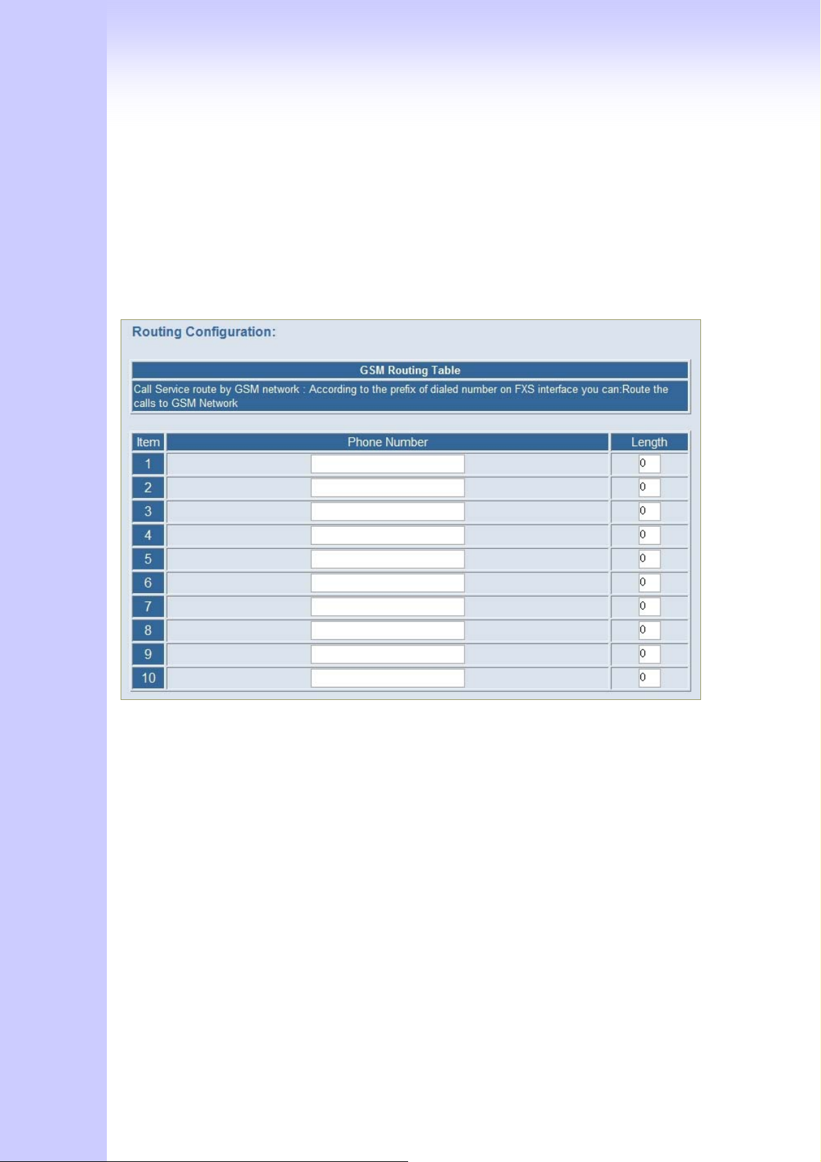
3.1.3 GSM Dialplan
GSM Numbers: The numbers which are filled in the form will go through GSM Network
unconditionally. You can use x as wild card.
For examples:
09x All telephone numbers start with 09
0919x All telephone numbers start with 0919
3.1.4 SMS Setting
27
Page 28
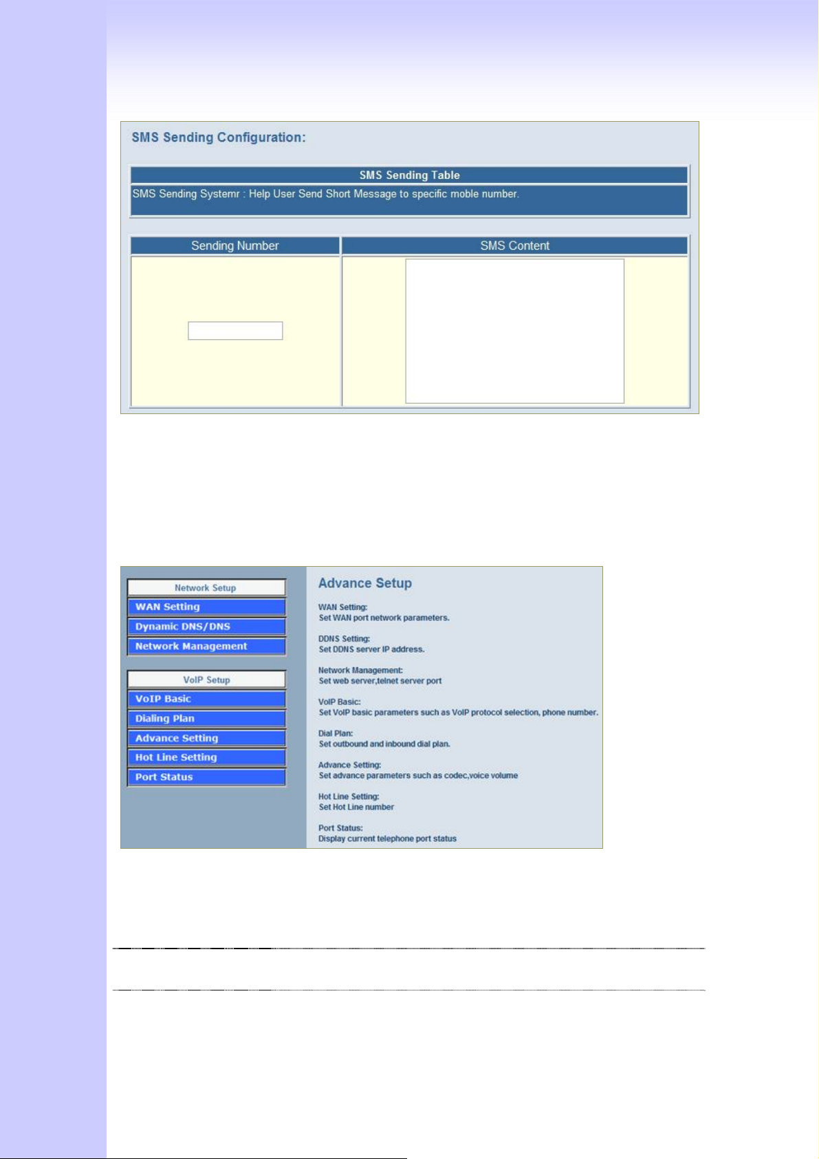
Sending Number: The telephone number which an short message is sent to.
SMS Content: The SMS Content will be sent to the preset telephone number. If the
SMS text is blank,an empty SMS is sent. The Maximum capacity is 40 characters.
Advanced Configuration
Network Setup
WAN Setting Sets/changes the WAN port Type like “Fixed IP”, “DHCP Client”
or ”PPPoE”.
Dynamic DNS Dynamitic DNS allows you to provide Internet users with a
domain name to access your server.
Network Parameters Network Parameter allows you to modify the access port of
gateway. For example :
28
Page 29
Setting HTTP port : 8080
Setting TELNET port is : 8081
(Default HTTP :80, TELNET: 23)
VoIP Setup
V100 only (with VoIP gateway features)
VoIP Basic The S Series Gateway support 2 / 4 / 8 / 16 / 24 phone/line
for SIP and H.323 VoIP call applications. You can configure
these ports from this menu.
Dialing Plan Users could apply any dial policy by setting Dial Plan including
outgoing dial plan and incoming dial plan.
Advanced Setting VoIP Gateway support for silence compression, DTMF Relay,
Codec Selection, FAX mode Option,
H323 Register Type and H.323 Fast-Start/Normal-Start
function.
Volume Adjustment, RRQ TTL, RFC2833 Payload, IP TOS,..etc
Hot Line Setting Let user can set up “hotline” to dial the phone number
automatically.
Port Status Display the telephone interface status
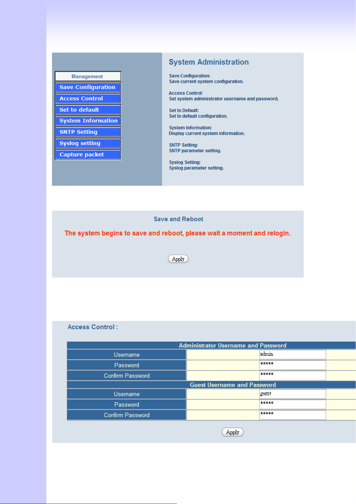
System Administration:
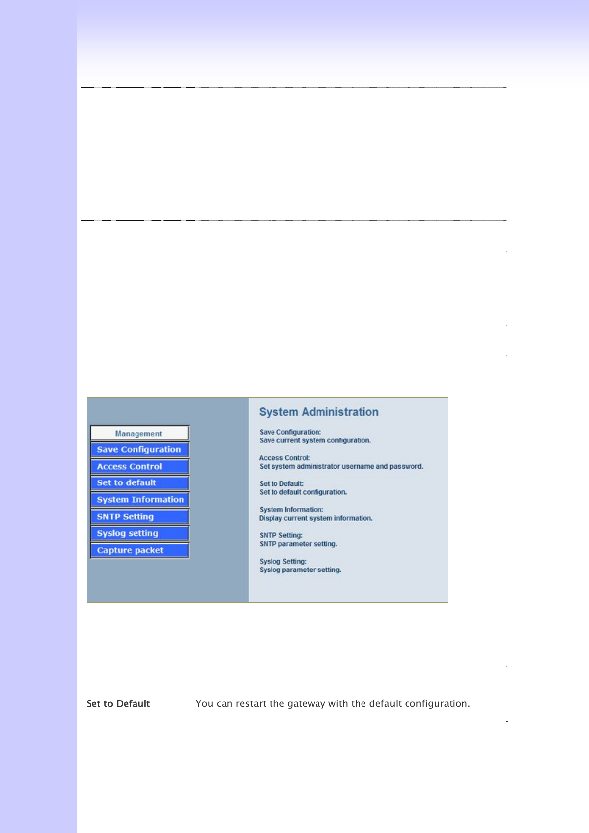
Management Label
Save Configuration You can save configuration and restart the gateway with the
default configuration or with the current running configuration.
Access Control Users can Sets/changes the administrator password..
Set to Default You can restart the gateway with the default configuration.
29
Page 30
System Information Display Software version, WAN Type, VoIP Status, VoIP Codec,
Phone Interface and System Tim.
SNTP Setting SNTP (Simple Network Time Protocol) Configuration for
synchronizing gateway clocks in the global Internet.
Syslog Setting Gateway can sends log information to Syslog Server by UDP ports
514.
Capture Packets The gateway supports packets capture and save the packets to
your PC. User can use Network Protocol Analyzer “Ethereal” to
analysis the packets.
(Free download from http://www.ethereal.com/)
4.1 Network Configuration
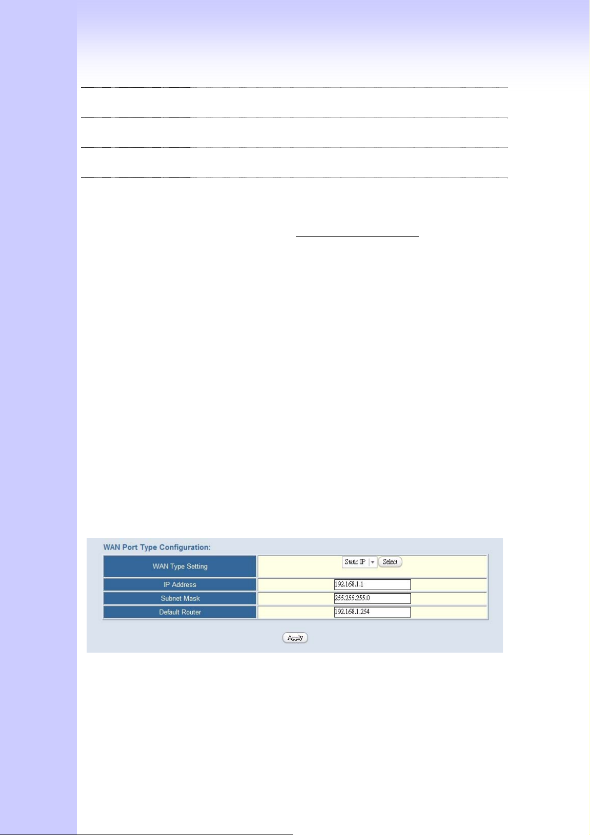
4.1.1 WAN Port Type Setup
For most users, Internet access is the primary application. The GSM Gateway support
the WAN interface for Internet access and remote access. The following sections will
explain more details of WAN Port Internet access and broadband access setup. When you
click “WAN Setting”, the following setup page will be show. Three methods are available
for Internet Access.
Static IP
PPPoE
DHCP
Static IP:
You are a leased line user with a fixed IP address; fill out the following items with the
information provided by your ISP.
IP Address: check with your ISP provider
Subnet mask: check with your ISP provider
Default Gateway: check with your ISP provider
PPPoE for ADSL
30
Page 31
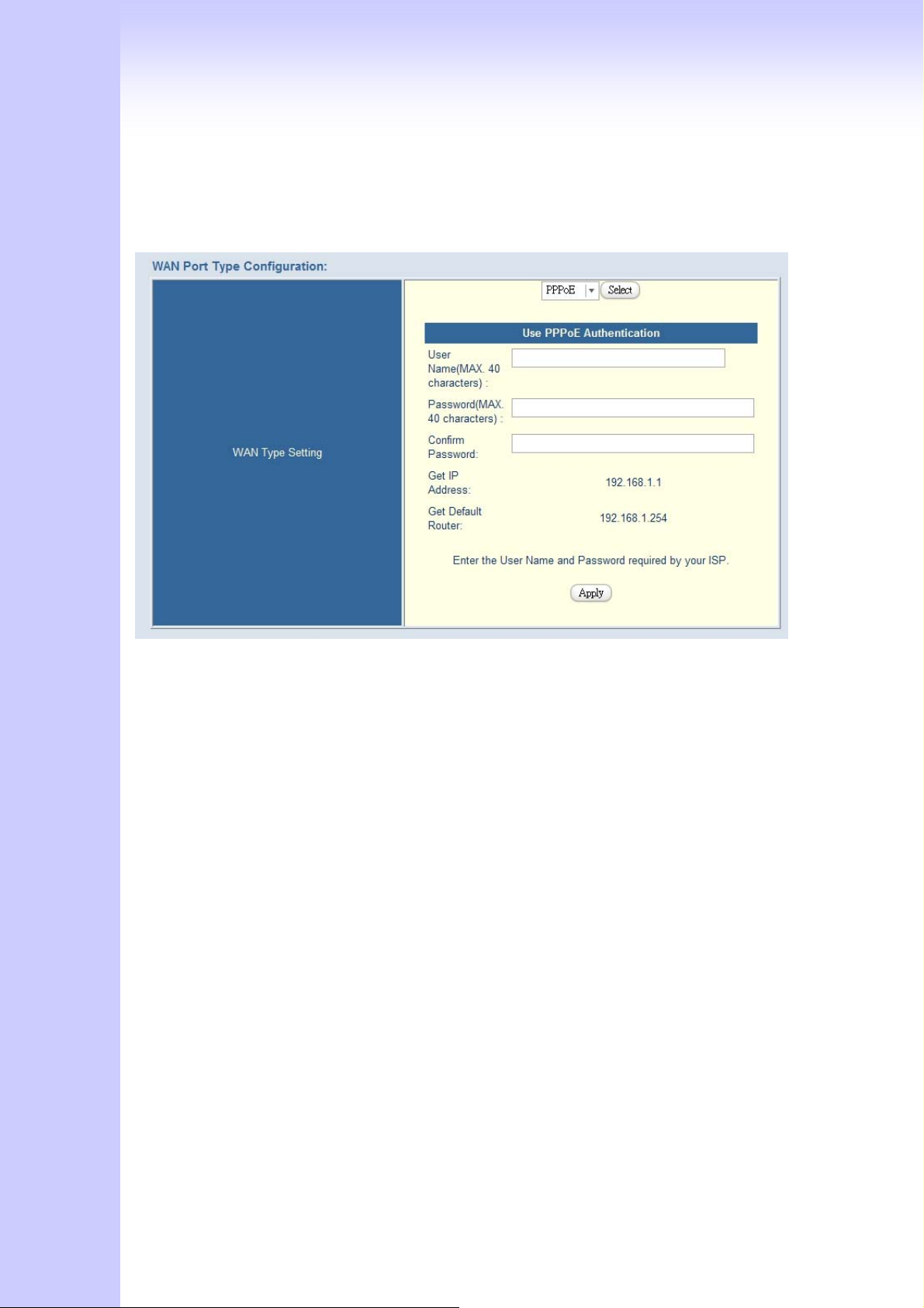
Some ISPs provide DSL-based service and use PPPoE to establish communication link
with end-users. If you are connected to the Internet through a DSL line, check with your
ISP to see if they use PPPoE. If they do, you need to select this item.
User Name: Enter User Name provided by your ISP
Password: Enter Password provided by your ISP.
Retype Password: Enter Password to confirm again.
DHCP Client (Dynamic IP):
Get WAN IP Address automatically
31
Page 32

IP Address: If you are connected to the Internet through a Cable modem line then a
dynamic IP address will be assigned.
(Note : WAN port display the IP address, Subnet Mask and Default gateway IP address if
DHCP client is successful)
4.1.2 Dynamic DNS
DDNS is a service that maps Internet domain names to IP addresses. DDNS serves a
similar purpose to DNS: DDNS allows anyone hosting a Web or FTP server to advertise a
public name to prospective users. Unlike DNS that only works with static IP addresses,
DDNS works with dynamic IP addresses, such as those assigned by an ISP or other DHCP
server. DDNS is popular with home network, who typically receive dynamic,
frequently-changing IP addresses from their service provider. To use DDNS, one simply
signs up with a provider and installs network software on their host to monitor its IP
address.
How to use DDNS
First: you should register a new DDNS service account from this web site:
http://www.dyndns.com/newacct
(Attention, if you use static IP address, you can’t set DDNS in gateway. Use DDNS and
Static IP at the same time, the dyndns will stop your DDNS service. Dyndns support
DDNS service is Free, one account can create 5 different DDNS Domain Name )
32
Page 33
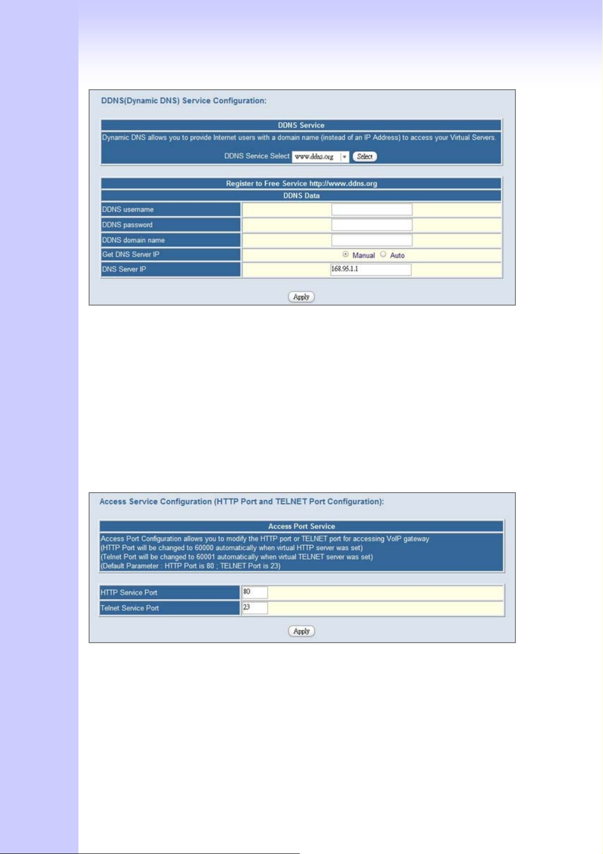
User Name: Input your DDNS User Name
Password: Input your DDNS Password
Domain Name: Input you set from your DDNS.(ie.gateway.gotdns.com)
DNS Server IP: Input your DNS Server IP.
4.1.3 Network Management
Network Management,, access port configuration allows you to modify the HTTP port
or TELNET port for accessing VoIP gateway
(Default Parameter : HTTP Port is 80 ; TELNET Port is 23)
Http Server Port: Input you want to change Web access port (Default is 80)
Telnet Server Port: Input you want to change telnet access port (Default is 23)
33
Page 34
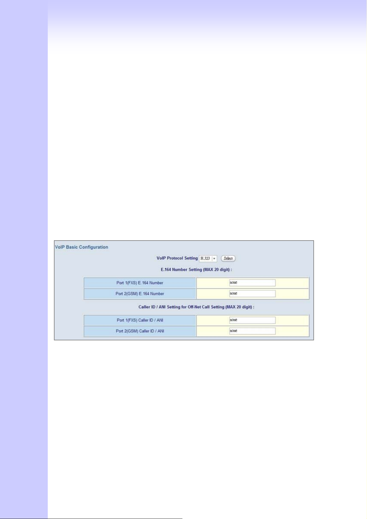
4.2 VoIP Setup (V100 only)
GSM Gateway support 2 VoIP protocol - H.323 / SIP, you can register to H.323
Gatekeeper or SIP proxy server. Gateway is not a softswitch, it only can use 1 VoIP
protocol (SIP/H.323) at the same time! If you don’t register GK or Proxy server, you can
make Peer to Peer call by IP address or domain name (Setting Dialing plan).
4.2.1 H.323 Setup
Gateway H.323 protocol support H.323 (v2/v3/v4), H.225, Q.931, H.245 and
RTP/RTCP. Don’t support H.235 security, can’t use H.235 security Authentication
Username / Password. H.323 protocol is not good at pass NAT/Firewall, the best way is
installed gateway on Public IP Address when it use H.323.If you want to under NAT,
gateway support NAT pass function when you use the same S Series Gateway. Other
band gateway doesn’t promise this function can work fine!
1. Configure the numbering with FXS / GSM ports.
FXS Port Number: The representation number is the phone number of the telephone
that is connected to FXS port.
GSM Port Number: The representation number is the phone number of SIM CARD
(Port number is in comparison with gateway port number. White Port socket is “GSM”
port, Black Port socket is “FXS” port.)
2. Configure the ANI (Answer Number Indication) / Caller ID of the FXS/GSM ports.
ITSP needs ANI for authorization when gateway calls Off-Net call to PSTN number or
34
Page 35
mobile phone number.
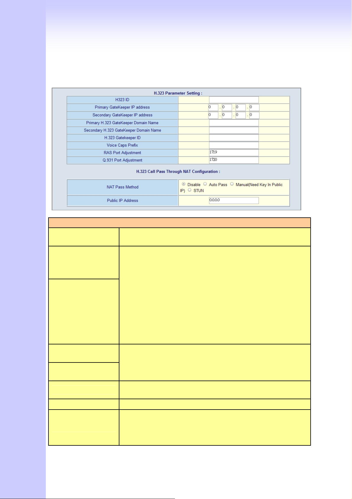
4. Register to H.323 Gatekeeper
(If user does not have Gatekeeper, Please go to Dialing Plan Policy)
H.323 Parameters Label
H.323 ID
Sets the unique name of this Gateway, that is communicated as
part of H.323 messaging..
There are two gatekeeper address fields, one is primary, the other
Primary Gatekeeper
IP Address
secondary. If this gateway does not want to register to any
gatekeeper, just set value 0 to the primary gatekeeper address. If
the primary gatekeeper address is not 0, the gateway will register
to the primary gatekeeper. If the second gatekeeper is not 0, the
gateway will try to register to the second gatekeeper when failed
Secondary
Gatekeeper
IP Address
to register to primary gatekeeper, i.e. if both the primary
gatekeeper and second gatekeeper addresses are present, the
gateway will try to register to these two gatekeepers respectively.
The gateway can have the gatekeeper backup function by this
way.
Primary Gatekeeper
Domain Name
Let user use Domain Name of H.323 Gatekeeper.
Secondary Gatekeeper
Domain Name
H.323 Gatekeeper ID
The Gatekeeper ID; usually do not need to set this field unless the
gatekeeper must need this value.
Voice Cap Prefix Let user set prefix number in RRQ nonstandard voice cap entry.
In H.323 standard the RAS default port number is 1719. The VoIP
RAS Port Adjustment
gateway provides user to change RAS port number to meet the
network environment.(Some area carrier blocks or forbidden the
default port number)
35
Page 36
In H.323 standard the default Q.931 port number is 1720. The
Q.931 Port
Adjustment
VoIP gateway provides user to change Q.931 port to meet the
network environment. (Some area carrier blocks or forbidden the
default port number)
H.323 Call Pass through NAT
1. Disable : The Gateway operates in public IP address
2. Auto Detection: When the Gateway register to GNU Gatekeeper
H.323 Pass Through
NAT method
/ H.323 Gatekeeper (SK Series), please select this option.
3. Manual Setting: When the Gateway registers to H.323
Gatekeeper and operate under NAT (enable DMZ), please select
this option and key in IP address.
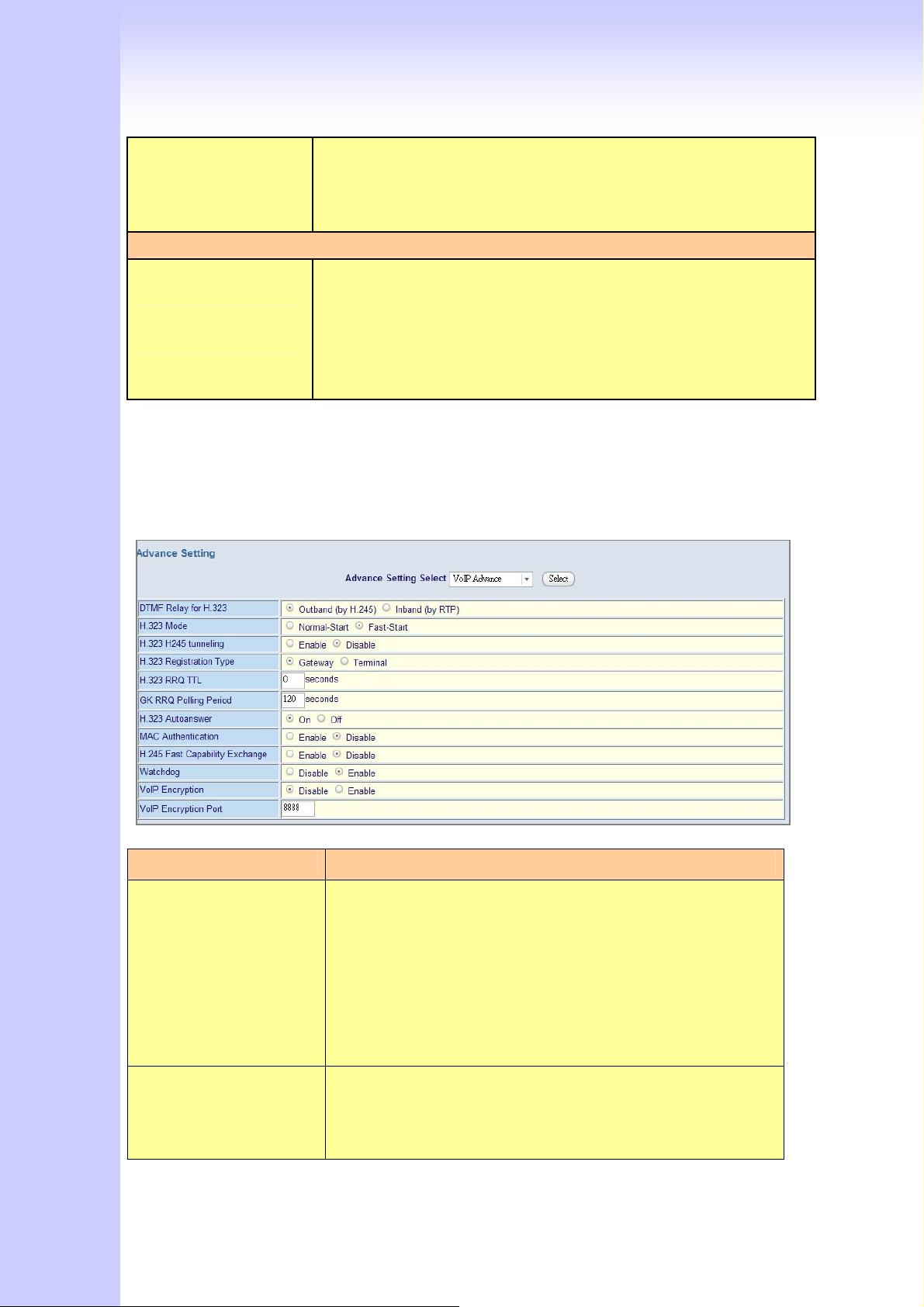
H.323 VoIP Advanced Configuration
There are many H.323, VoIP, Codec and other more detail Setting, you can set in
“Advance Setting”. For SIP and H.323, there are a little different in advance setting. There
are 3 different parts to setting about VoIP, Telephone and network.
[Advance Setting]
Item Description
DTMF Relay for H.323: After the VoIP call is connected, when you dial a digit, this
digit is sent to the other side by DTMF tone. There are two
methods of sending the DTMF tone. The first is “in band”,
that is, sending the DTMF tone in the voice packet. The
other is “out band”, that is, sending the DTMF tone as a
signal. Sending DTMF tone as a signal could tolerate more
packet loss caused by the network. If this selection is
enabled, the DTMF tone will be sent as a signal.
H.323 Mode: This selection could force the Gateway to use normal start
mode (default mode) or fast start mode when establishing a
VoIP call. Many other gateways only support normal start
mode, enable this selection when it is necessary. The
36
Page 37

default is disabled (using fast start mode).
H.323 H.245 Tunneling: This selection could force the Gateway to use H.245
Tunneling when establishing a VoIP call The default is
disabled (using fast start mode).
H.323 Registration type: There are 2 choices for this setting. “Gateway” means it will
act as the VoIP gateway. “Terminal” means it will act as the
IP phone terminal.
H.323 RRQ TTL: This command configures the number of seconds that the
gateway should be considered active by the H.323
gatekeeper. The gateway transmits this value in the RRQ
message to the gatekeeper. The default value is “0”.
H.323 Autoanswer: When a VoIP call is incoming, the Gateway will ring a
specific phone set. The H.323 call signaling part could be
connected or alerting during this ringing period. If this
selection is enabled, the H.323 signaling part is connected
during the ringing period. The benefit of this situation is
that the remote side could hear the status of the specific
port. That is, the remote side will hear ring back tone if the
Gateway is really ringing the phone set. If the phone set is
busy, the remote side will hear busy tone. The disadvantage
of this situation is that the H.323 connected time is not the
real voice call connected time. So, if billing is recorded for
this Gateway, this function should be disabled.
MAC Authentication:
Watchdog: When your gateway shutdown, or something happen that
[Telephone Advance]
Some Gatekeeper register need UA send MAC address to
Authentication, you need enable this function.(Default is
disable).
made gateway can’t work fine. Watchdog will reboot your
gateway automatically when it can’t work.
37
Page 38
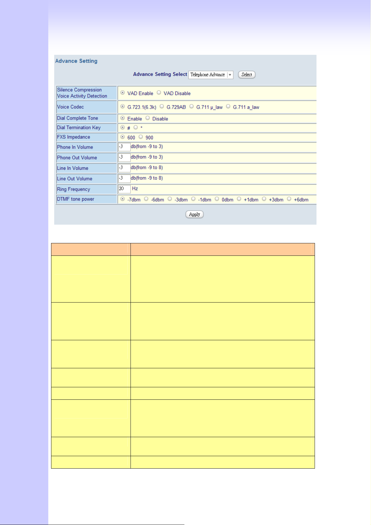
Item Description
Silence Compression:
(VAD)
Voice Codec option: The Codec is used to compress the voice signal into data
Dial Complete Tone:
Dial Termination key:
FXS Impedance: The FXS provides 600/900 OHM impedances for selection.
Phone (Line) in/out
volume:
Ring Frequency: You can configure how long the Ring Frequency do you
DTMF tone power: Sometimes you input DTMF, but no request. You can adjust
If this function is enabled, when silence is occurred for a
period of time, no data will be sent across the network
during this period in order to save bandwidth.
(If you use Asterisk, please disable Silence Compression, it
maybe make you call disconnect.)
packets. Each Codec has different bandwidth requirement.
There are four kinds of Codec, G.723, G.729AB, G.711_u
and G.711_A. The default value is G.723.
When you use the VoIP call, you will heard “DuDu” voice that
is dial complete tone. If you don’t want to heard that tone ,
you can disable it.(default is enable).
Setting Termination key to speed up VoIP dial. Select “*” or
“#” to Termination key.
You can adjust the Phone (Line) in/out volume, range from
-9db to 9db
(If you adjust too bigger, maybe generation some ECHO or
noise)
want to use.
38
Page 39
this function, range from -6db to +6db.
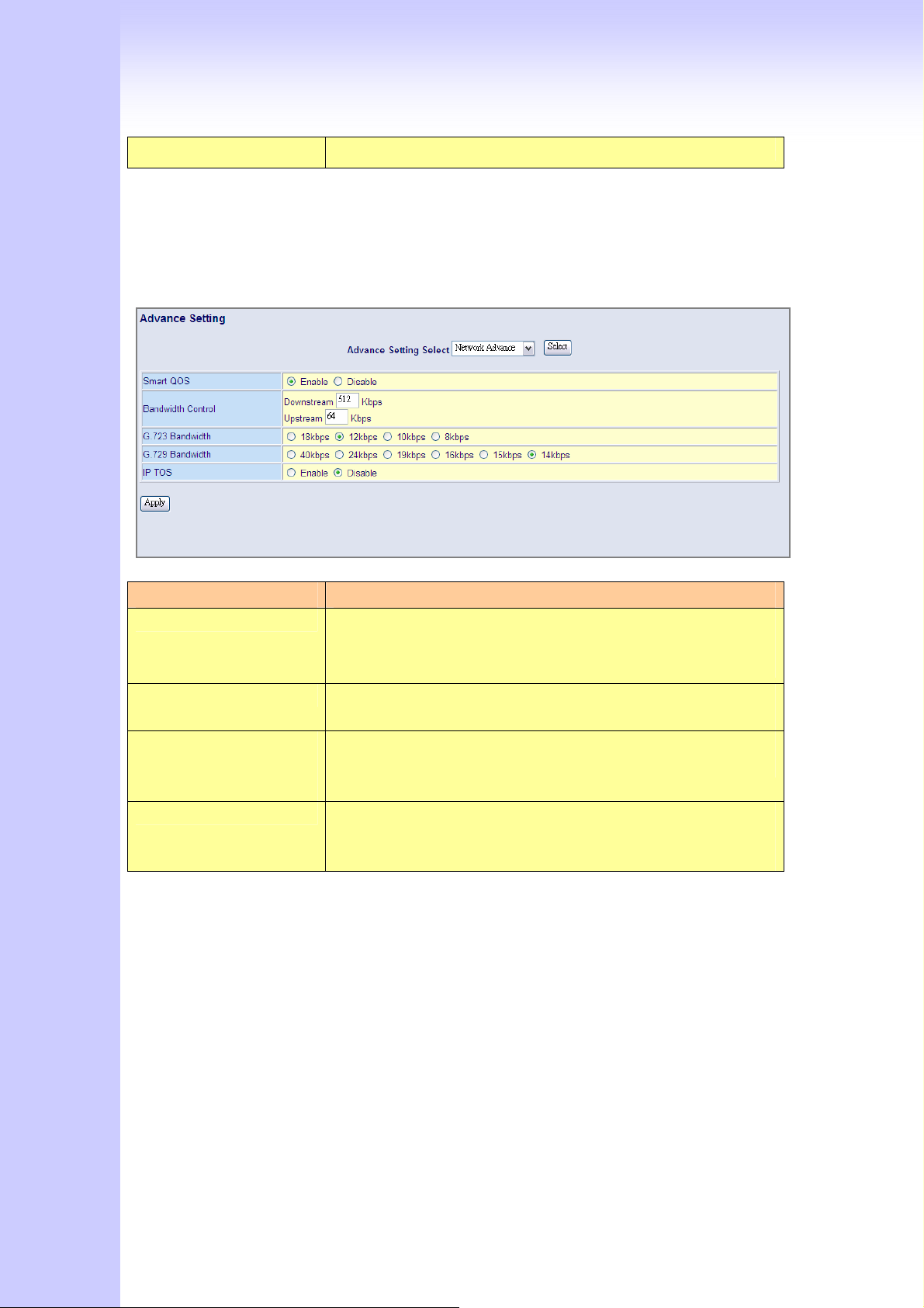
[Network Advance]
Item Description
Smart-QoS: If this function is enabled, when VoIP call is occurred, the
other data will be automatically reduced traffic which across
the internet in order to guarantee the voice bandwidth.
Bandwidth control: You can configure your bandwidth what the Max byte of
download and upload of ADSL modem rate.
G.723/G.729
Bandwidth:
IP TOS: Some Router support TOS(Type of Service), when you
Setting G.723 / G.729 voice compression size. Quality and
Packet size can adjust by you want.
enable the TOS function, the router will process those
packets firstly.(default is disable)
4.2.2 SIP Setup
Gateway SIP support SIP(RFC3261), SDP(RFC2327), RFC2833, STUN(RFC3489),
Symmetric RTP, outbound proxy, ENUM(RFC2916),and RTP/RTCP.SIP NAT pass through
Function can support 80% NAT/Firewall that you don’t setting DMZ/Virtual server in
router or Firewall.
39
Page 40
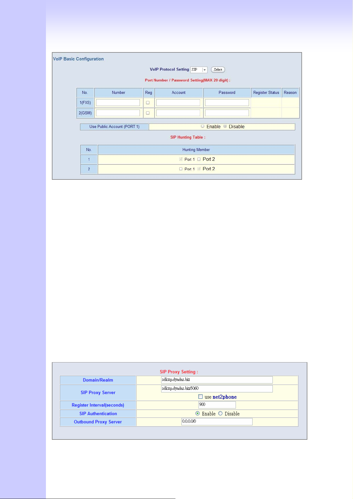
1. Select “SIP Protocol”
2. SIP number / account (username) and Password Setting: Please fill out the SIP account
including username / password from ITSP.
(Note: support digits and character base SIP Account / username, some SIP Server use
character username to login, and a number to call number( ie. VoIPBuster) , if your
server don’t support this, number/Account are the same, please input the same
username )
Number: Input SIP Number(Username), if your server support account and number
(different),input the number, else number/account are the same username.
Reg: let your sip account register SIP Server, click this option.
Account: Input SIP account(Username), if your server support account and number
(different),input the number, else number/account are the same username.
Password: Input Password that ITSP support.
Use Public Account: This allows gateway can use single SIP account for multiple ports.
User input the only one account in port one field for registering the ITSP.
3. SIP Proxy Server setting, setting SIP proxy server register information.
(If user does not need register SIP Proxy Server, Please go to Dialing Plan Policy)
40
Page 41
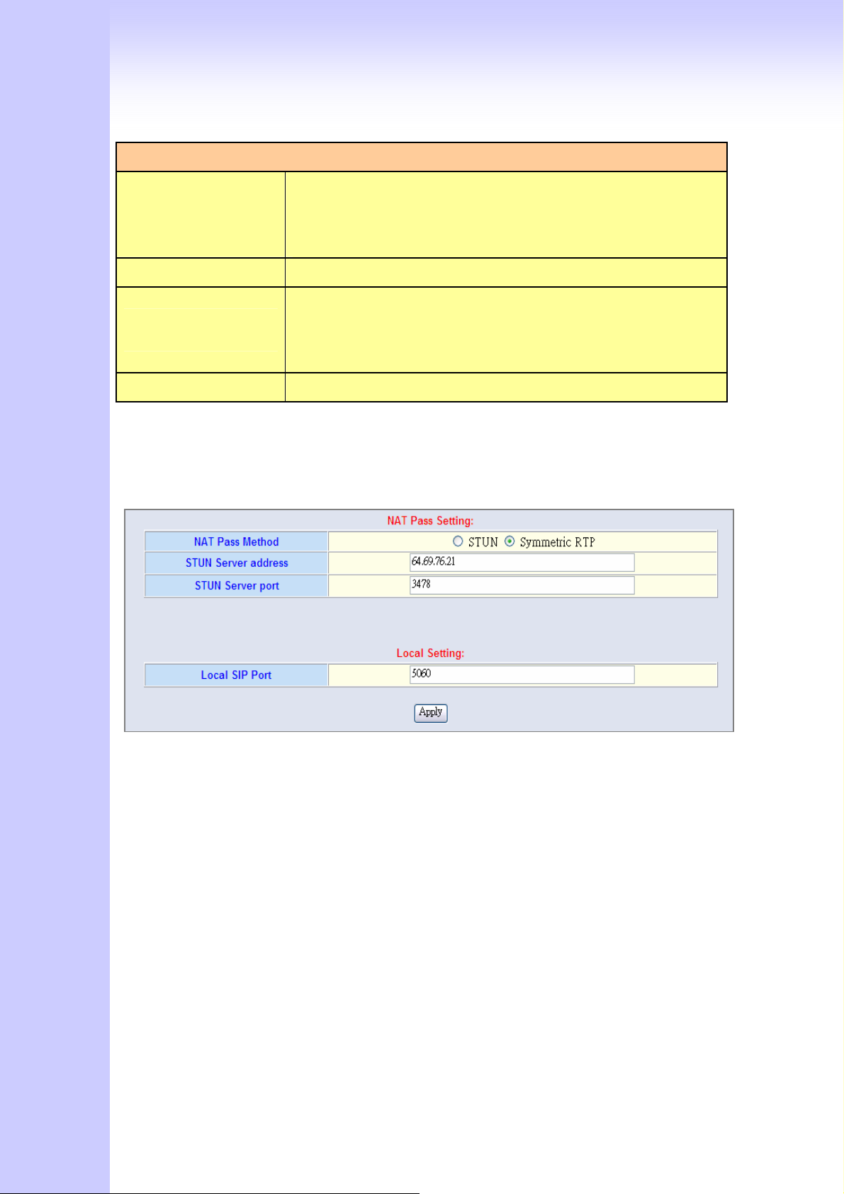
SIP Proxy Server Label
1. Enter the SIP service IP address or domain name in this field
SIP Proxy Server
Setting
(the domain name that comes after the @ symbol i n a full
SIP URI).
2. Use Net2Phone Service Provider
SIP Domain 1. Enter the SIP realm in this field
This field sets how long an entry remains registered with the
Register Interval
Setting
SIP register server. The register server can use a different time
period. The Gateway sends another registration request after
half of this configured time period has expired.
SIP Authentication Enable or Disable MD5 Authentication with SIP Proxy Server
4. If your gateway under the NAT/Firewall, you should setting different NAT Pass
function. if you setting STUN/Outbound Proxy, you should have a STUN/Outbound
proxy server. If they can’t pass NAT or one way talk happen, try to open “DMZ” and
virtual server “5060” port in router.
Symmetric RTP: default use Nat pass function.
STUN Client: setting your STUN server information, default STUN server is FWD STUN
server.
Outbound Proxy Support: Setting your Outbound Proxy server information.
Local SIP Port:: setting local use SIP port, default is 5060.
SIP VoIP Advanced Configuration
There are many SIP VoIP, Codec and other more detail Setting, you can set in
“Advance Setting”. For SIP and H.323, there are a little different in advance setting. There
are 3 different parts to setting about VoIP, Telephone and network.
[VoIP Advance]
41
Page 42
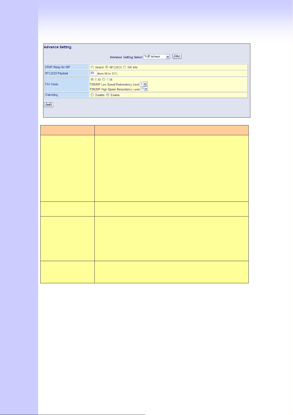
Item Description
DTMF Relay for SIP: After the VoIP call is connected, when you dial a digit, this digit
is sent to the other side by DTMF tone. There are three
methods of sending the DTMF tone. The first one is “in band”,
that is, sending the DTMF tone in the voice packet. The second
one is “RFC2833”, that is, sending the DTMF tone as a RTP
payload signal. The third one is “SIP Info”, that is, sending the
DTMF tone as a SIP signal. Sending DTMF tone as a signal could
tolerate more packet loss caused by the network. If this
selection is enabled, the DTMF tone will be sent as a signal.
RFC2833 Payload: Adjust RFC2833 DTMF payload value, range from 96 to 127,
default is 101.
FAX Mode Option: T.30/T.38 real-time FAX compliant Voice/FAX auto-switch. The
T.38 is a “Real Time Group 3 Fax Communication over IP
network” format. That’s meaning it’s a protocol for Fax over IP.
You have to enable this function
(T.38 mode isn’t support all gateway, different band use T.38
have a little change, it maybe let T.38 FAX Error)
Watchdog: When your gateway shutdown, or something happen that made
gateway can’t work fine. Watchdog will reboot your gateway
automatically when it can’t work.
[Telephone Advance]
42
Page 43
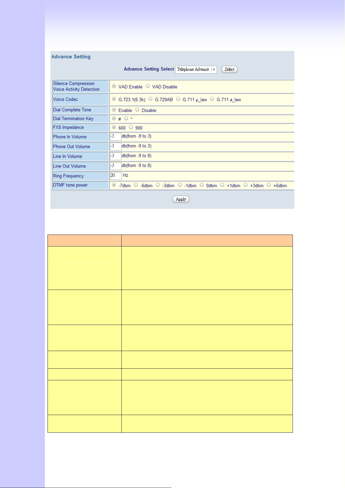
Item Description
Silence Compression:
(VAD)
Voice Codec option: The Codec is used to compress the voice signal into data
Dial Complete Tone:
Dial Termination key:
FXS Impedance: The FXS provides 600/900 OHM impedances for selection.
Phone (Line) in/out
volume:
Ring Frequency: You can configure how long the Ring Frequency do you
If this function is enabled, when silence is occurred for a
period of time, no data will be sent across the network
during this period in order to save bandwidth. (If you use
Asterisk, please disable Silence Compression, it maybe
make you call disconnect.)
packets. Each Codec has different bandwidth requirement.
There are four kinds of Codec, G.723, G.729AB, G.711_u
and G.711_A. The default value is G.723.
When you use the VoIP call, you will heard “DuDu” voice that
is dial complete tone. If you don’t want to heard that tone ,
you can disable it.(default is enable).
Setting Termination key to speed up VoIP dial. Select “*” or
“#” to Termination key.
You can adjust the Phone (Line) in/out volume, range from
-9db to 9db.
(If you adjust too bigger, maybe generation some ECHO or
noise)
want to use.
43
Page 44
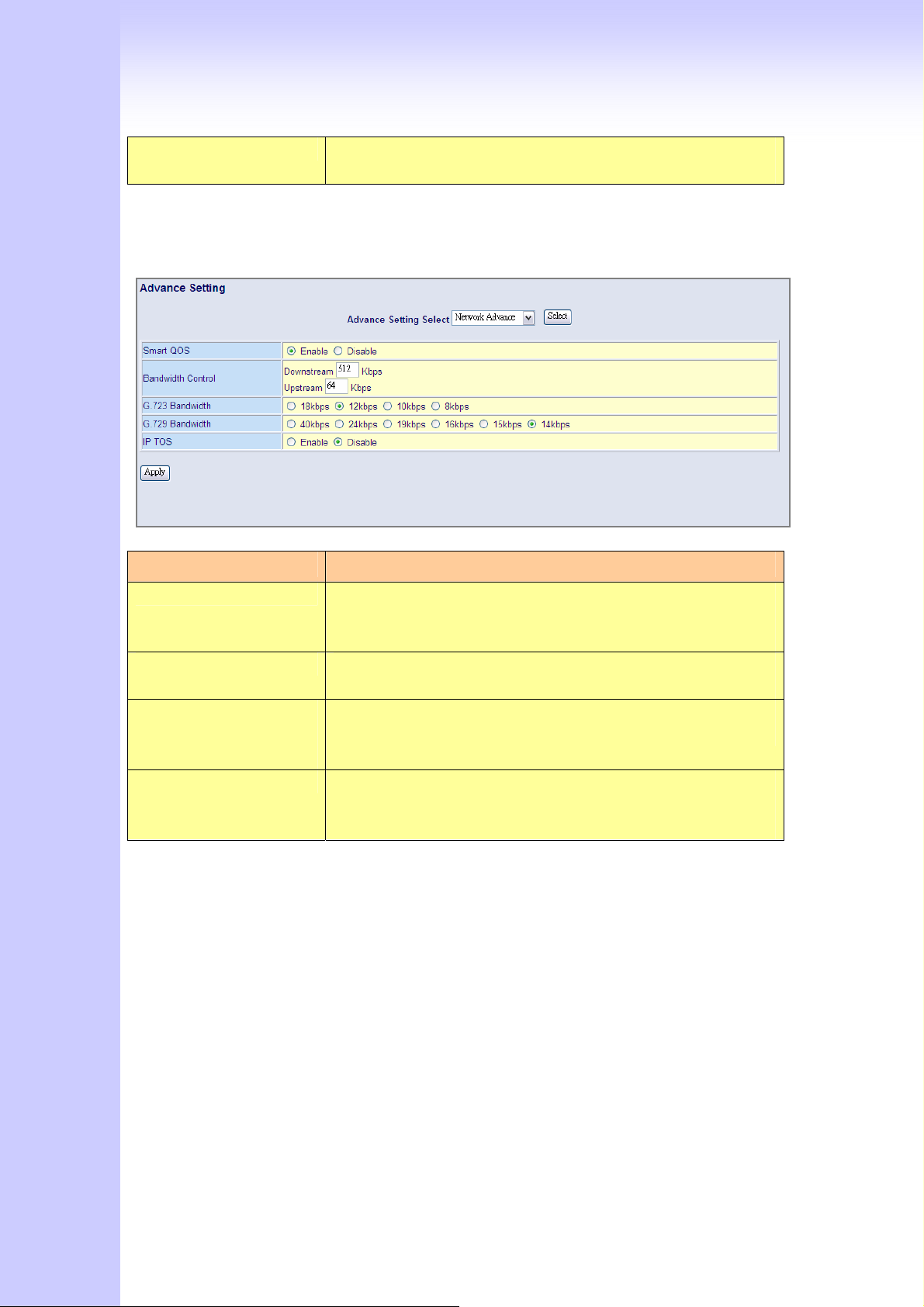
DTMF tone power: Sometimes you input DTMF, but no request. You can adjust
this function, range from -6db to +6db.
[Network Advance]
Item Description
Smart-QoS: If this function is enabled, when VoIP call is occurred, the
other data will be automatically reduced traffic which across
the internet in order to guarantee the voice bandwidth.
Bandwidth control: You can configure your bandwidth what the Max byte of
download and upload of ADSL modem rate.
G.723/G.729
Bandwidth:
IP TOS: Some Router support TOS(Type of Service), when you
Setting G.723 / G.729 voice compression size. Quality and
Packet size can adjust by you want.
enable the TOS function, the router will process those
packets firstly.(default is disable)
4.2.3 Direct call (Peer to Peer) setup
If you don’t registered Gatekeeper or SIP proxy server, you can make call by Peer to
Peer. For SIP or H.323, setting the dialing plan, and can make direct call.
Overview of the Dialing Plan
The “Dialing plan” need setting when the user use the method of Peer-to-Peer H.323
(SIP) VoIP call or registering H.323 Gatekeeper (SIP Proxy Server) Mode. The H.323(SIP)
Dialing Plan has two kinds of directions: Outgoing (call out) and Incoming (call in).
1. Outgoing Dial Plan:
Peer-to-Peer Call Mode: Effective
44
Page 45
Registering to H.323 Gatekeeper (SIP Proxy Server) Mode: Effective
2. Incoming Dial Plan:
Peer-to-Peer Call Mode: Effective
Registering to H.323 Gatekeeper (SIP Proxy Server) Mode:
The leading number would register to H.323 Gatekeeper (SIP Proxy Server)
When you use direct call, you must setting your VoIP protocol firstly. Use direct call,
you should setting the same protocol both of UA. Both of UA must support dial plan
function. Some ATA don’t support Dialing plan, it maybe let direct call failed.
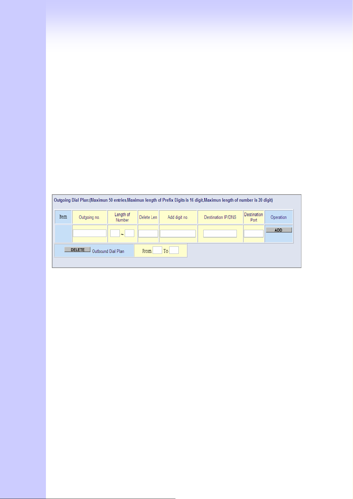
In the “Outgoing Dial Plan Configurations” settings: Maximum Entries : 50
“Outbound number” is the leading digits of the call out dialing number.
“Length of Number” has two text fields need filled: “Min Length” and “Max Length” is
the min/max allowed length you can dial.
“Delete Length” is the number of digits that will be stripped from beginning of the
dialed number.
“Add Digit Number” is the digits that will be added to the beginning of the dialed
number.
“Destination IP Address / Domain Name” is the IP address / Domain Name of the
destination Gateway that owns this phone number.
“Destination Port” is port of the destination gateway use.(Default is 5060)
Example1: Normally Dial
45
Page 46
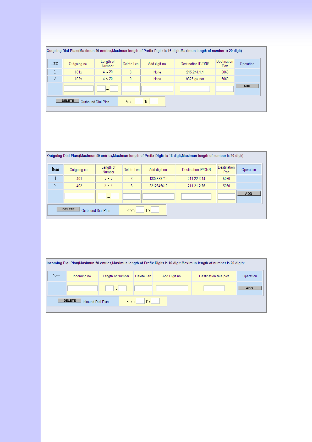
1.001x leading call out, call to Destination IP address: 211.22.3.14
2.002x leading call out, call to Destination Domain Name: h.323.gw.net
Example2: Speed Dial
1. If user dial “401”,
Gateway automatically dial “1334588712” to Destination IP address: 211.22.3.14
2. If user dial “402”,
Gateway automatically dial “2212345612” to Destination IP address: 211.21.2.76
In the “Incoming Dial Plan Configurations” settings: Maximum Entries : 50
“Inbound number” is the leading digits of the dialing number.
“Length of Number“ has two text fields need filled: “Min Length” and “Max Length” is
the min/max allowed length you can dial.
“Delete Length” is the number of digits that will be stripped from beginning of the
dialed number.
“Add Digit Number” is the digits that will be added to the beginning of the dialed
number.
“Destination Tele port” is “Tel-port”; this is for local dial plan setting phone number.
4.2.4 Other VoIP Setting
46
Page 47
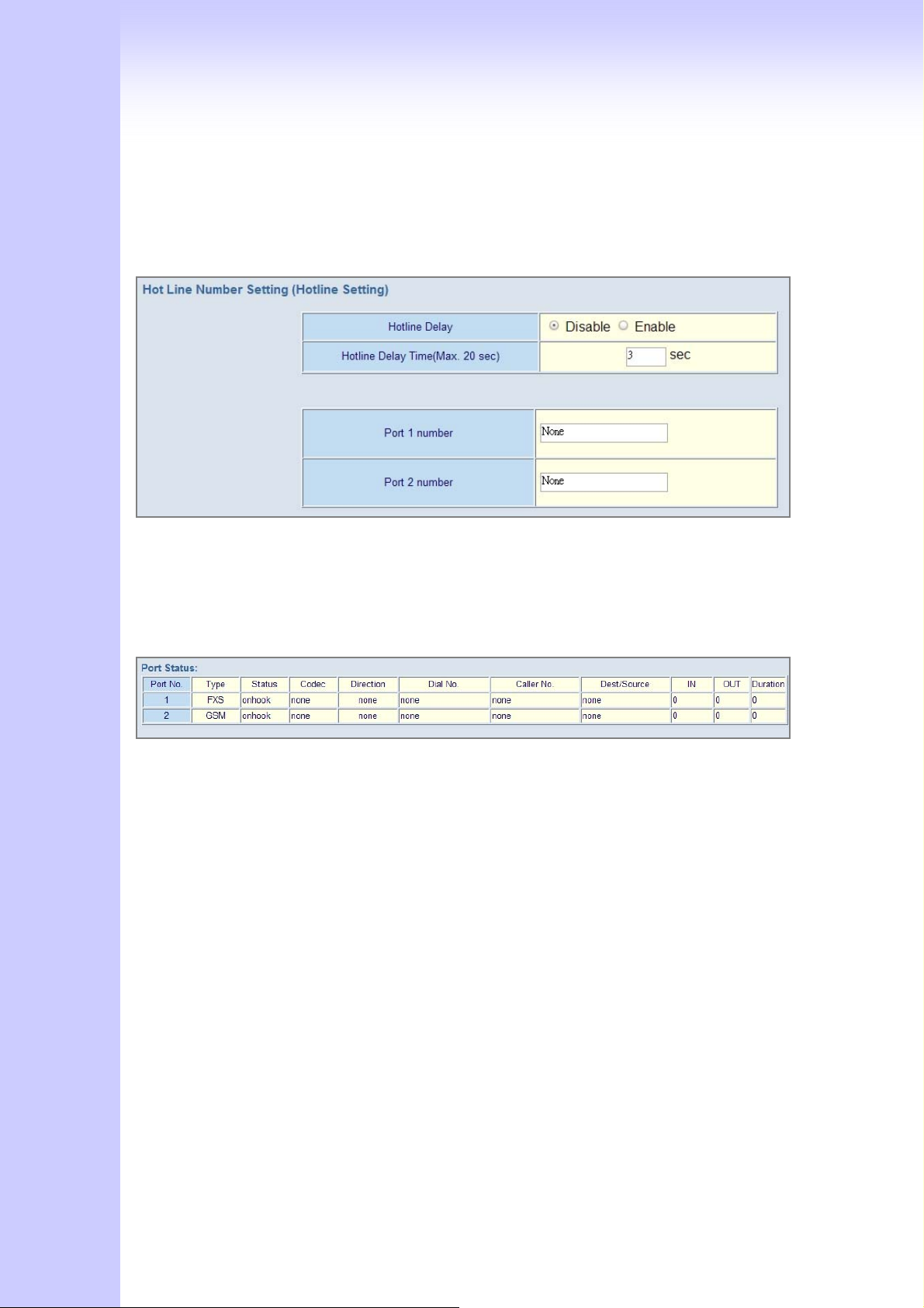
Hot Line:
You can setting hot line. when the call incoming the hot line port, it will call hot line
number automatically. The hot line call the number via VoIP, so you setting the hot line
number must VoIP number. Usually, you want to incoming GSM calls transfer to FXS, you
only setting the GSM hot line to FXS number.
Port number: Input FXS/GSM want to call hot line number. The call will via VoIP, so
the number must be the VoIP number.
Port Status:
Each of port show status table. you can view all port status. Like on/off hook ,
caller/callee IP, duration , and packet loss.
Port Status Display: This selection will display concurrent call status of this Gateway.
The status information of each voice channel includes codec, dialing number and
destination IP address. The status is refreshed every 3 seconds.
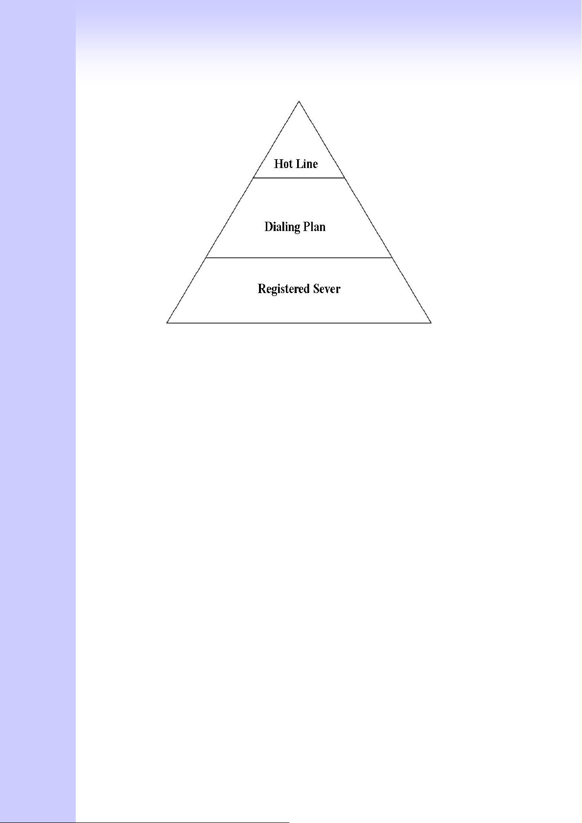
Call Priority:
Gateway have a rule for call Priority, up to down is 1)Hot Line 2)Dialing plan
3)Registered server(SIP Proxy / H.323 Gatekeeper).When a VoIP call made, Gateway will
process by Hot Line first, then it will check the dialing plan table, last fine
Server(SIP/H.323).
For example, if I have a gateway , and It is registered a proxy server, I don’t setting any
others (Hot Line or dialing plan.). when I make a VoIP call, gateway will check Proxy
server. Now,, I setting 1~2 dialing plan, and registered proxy server. When I call,
gateway will check the dialing plan first, then find the proxy server. And so on…..
47
Page 48
System Administrator
You can setting other gateway setting, like gateway time, Syslog that send CDR
information to Syslog server, backup and restore configuration.
48
Page 49
4.3.1 Save Configuration and Reboot
Click “
(When you set done, select “Reboot” option will auto save and reboot!)
Save Configuration and Reboot” to save configuration and begin to restart.
4.3.2 Access Control
49
Page 50
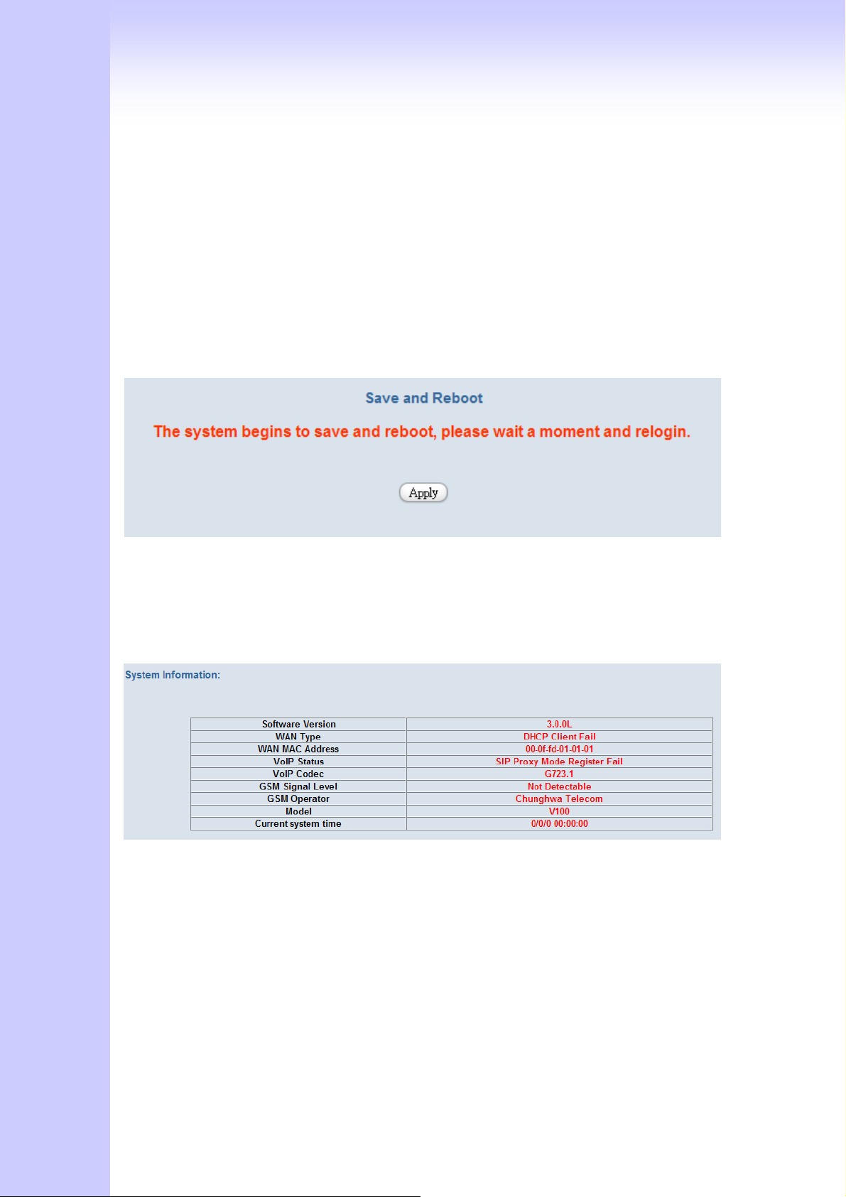
Changing the Administrator Password
For security reasons, we strongly recommend that you set an administrator.
password for the router. On first setup the router requires no password. If you don’t set
a password the router is open and can be logged into and settings changed by any user
from the local network or the Internet.
Click Access Control Setup, the following screen will open.
(Guest account , if you use guest account login , you only can view gateway setting, not
change and configure any gateway setting, else you login by Admin account)
4.3.3 Set To Default Configuration
If you want to reboot the router using factory default configuration, click “Apply”
then reset the router’ s settings to default values.
4.3.4 System Information Display Function
Click System Information Display to open the Online Status page. In the example, on
the following page, both PPPoE connection is up on the WAN interface, H323 Status,
MAC address, Register Status, etc….
4.3.5 SNTP Setting Function
Click SNTP Setting to open the Online Status page. In the example, on the following
page,
.
50
Page 51
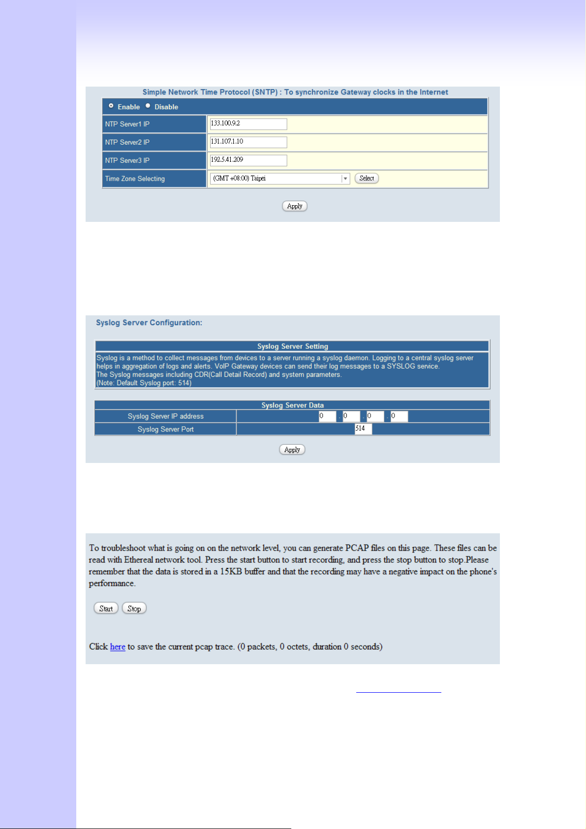
Use SNTP Setting
to set the date and time . The Gateway synchronizes the Gateway’s time after you select
the time zone.
—When checked, Gateway uses a Simple Network Time Protocol (SNTP)
Use SNTP Setting
, Select the time zone which Gateway was at.
4.3.6 Syslog Setting Function
Use Syslog server to record your Gateway log file. you can setting you syslog server
IP address for this function. Syslog information include the CDR source!
4.3.7 Capture Packets Function
Use “Capturer Packets” to record Gateway packets. You can start and stop the
capture then save the file to PC Use the Ethereal Tool (www.ethereal.com
the packets.
(if gateway have interoperability problem, you can capture the packet, send to us . we
can refer this packet to bebug.)
) to analyze
51
Page 52

4.4 Update firmware
Gateway can upgrade Firmware via FTP, update firmware can add new function or fix
some bug. If your gateway works fine, you don’t need update any new firmware. The
new firmware maybe let your gateway not stable. you can get the last version firmware
on our web site or send support mail to us, we will mail firmware to you.
Firmware name is “v100.300”, the first name v100 is mean the gateway module.
(Gateway update firmware only support use telnet via FTP, no other else upgrade
function.)
FTP upgrade Requirement and Process
1. Environment Requirement
PC with FTP Server (Server-U software, 3CDaemon,..)
PC or Notebook witch connected to WAN port of Gateway.
Put the image (firmware) named “v100.xxx” at the assigned folder in FTP Server.
( for example: “v100.270” is version 2.7.0 )
Note: Our company FTP server, you can use it to upgrade
Free FTP server : 61.218.109.83
username: share , password: 19730809
Environment Architecture (Gateway and FTP server are in Internet):
52
Page 53
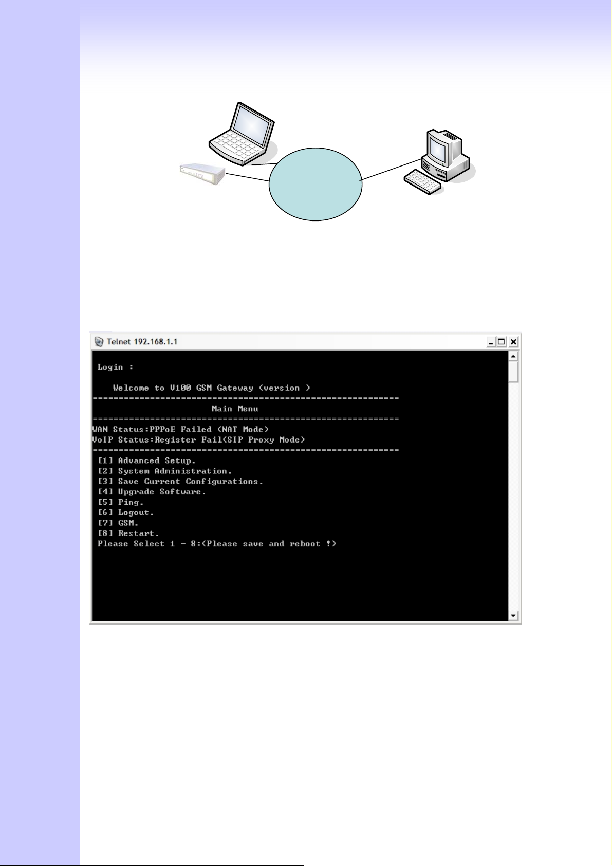
Notebook
IP of
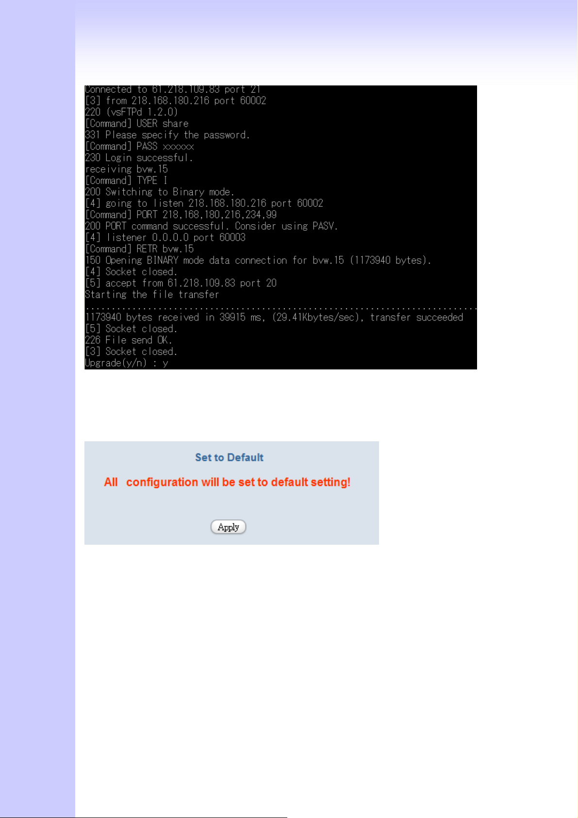
2. Upgrading Process
Notebook Telnet VoIP GW
[Open DOS mode]
C:> telnet [the IP of gateway]
Please select [4] Upgrade Software
FTP Server
Internet
Please input IP address of FTP server like as : 61.218.109.83
Username : share
Passswd : 19730809
Imagename: s400.271
Upgrade (y/n) : y , then will write the firmware to flash.
(In different module or firmware , maybe have different change)
53
Page 54
After writing flash, Please reboot the Gateway.
If the new firmware (image) was most different with the previous version, please push
the hardware reset bottom to set to default.
If the VoIP Gateway is in remote site, please use WEB configuration to set to default.
Soundwin Network, Inc. - Headquarters
10F-4, No. 295, Sec. 2, Guangfu Rd.,
Hsinchu City, Taiwan
Tel: +886-3-5733113
Fax: +886-3-5736131
54
Page 55

E-mail: [email protected]
Web Site: http://www.soundwin.com
Made by
Joey Lin
Appendix
A FAQ List
1. What is the default administrator password to login to the gateway?
A: By default, your default username is “admin”, default password is “admin” to login to
the router. For security, you should modify the password to protect your gateway
against hacker attacks.
2. I forgot the administrator password. What should I do?
A: Press the Reset button on the rear panel for over 5 seconds to reset all settings to
default values. Default username / password is admin / admin.
3. What is the default IP address?
A: The default WAN IP address is 192.168.1.1 with subnet mask 255.255.255.0.
4. What is different [set to default] and [Factory set to default]?
A: Factory set to default, you must push RST button until 5 second, gateway will clear all
your setting, and let gateway Wan port become the factory default (192.168.1.1). When
you use setting to default by Web or telnet, it will clear all your setting, but the wan port
setting will be saved. If you remote the gateway, after set to default, you can login
gateway again. No reset the gateway wan port again.
5. Why can I call out when the gateway under the NAT?
A: VoIP product almost have NAT Pass through problem. By SIP, there are many NAT
Pass through Function can solve 80% NAT Problem. You can choose STUN/Outbound
Proxy/ Symmetric RTP to Pass through NAT, you don’t set any other setting (DMZ/Virtual
Server) by router side. If you use STUN/Outbound Proxy, you must have a
STUN/Outbound Proxy Server to support. If they can’t pass NAT, please open the
DMZ/Virtual Server by Router/NAT/Firewall.
55
Page 56
6. Why does the one way talk happen?
A: Generally, one way talk happen when use the different codec between VoIP device
make call. Please check and setting the same codec, most one way talk will be solved.
7. Why can I call out by Gateway?
A: Please chick your Gateway is registered SIP Proxy Server (ITSP), and chink your
Internet works fine. Gateway can’t make a call without Internet or SIP Account that from
ITSP supply. You must have a SIP account or know the other Gateway IP/Domain Name,
then you can make a VoIP call.
8. Why I use asterisk by G.729 sometimes disconnect happen?
A: In asterisk setting VAD must disable, if you open Silence Compression (VAD), it will
make call disconnect happen, please disable the option when you use the asterisk.
9 Why can i register and use after setting?
A: After setting, please save configuration and reboot, after reboot you can use new
configuration.
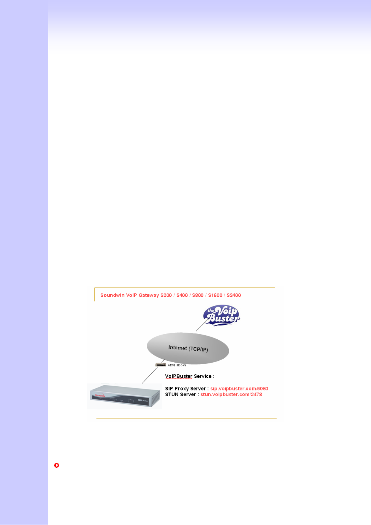
B SIP Setting VoIPBuster
VoIPBuster Service Using Soundwin VoIP Gateway
The Soundwin GSM Gateway VoIP Gateway can register to VoIPBuster
(http://www.voipbuster.com) VoIP service by SIP protocol and also can call SIP calls by
VoIPbuster (http://www.voipbuster.com) service.
Gateway Setting
56
Page 57
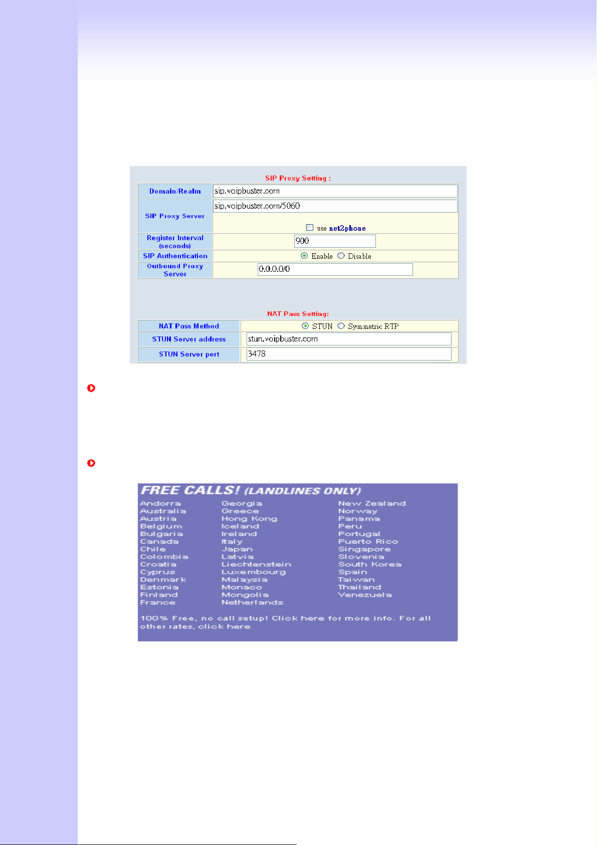
1. VoIPBuster SIP Proxy Server : sip.voipbuster.com / 5060
2. VoIPBuster STUN Server: stun.voipbuster.com / 5060
3. VoIP Basic -> Setting SIP accounts and Set the Proxy Server and STUN server.
How to dial the call?
00 - country code – area code
For example soundwin company phone number is +886-35733113, the dial number
is 0088635733113
VoIPBuster Provides Free Land Line (Fixed Line) Calls
C Sip Speeds call
Speed Call Concept:
57
Page 58
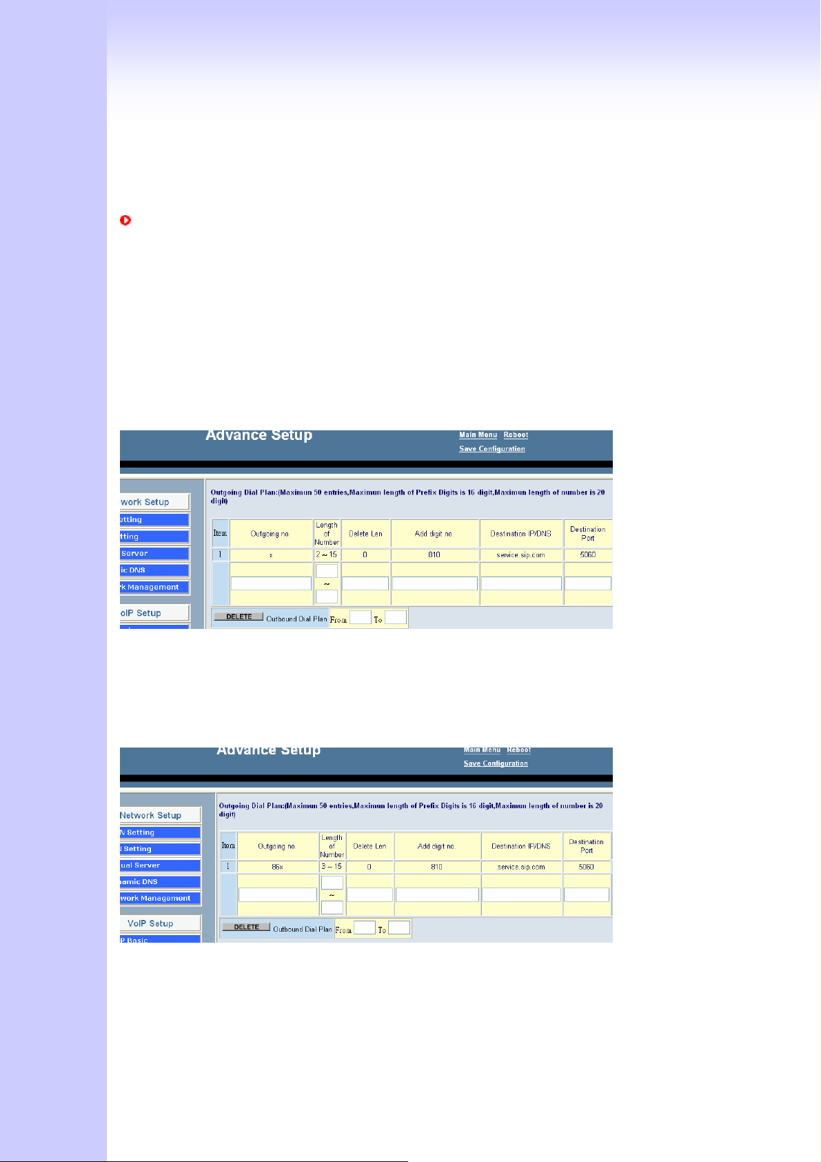
Cut your phone number down to fewer digit dialing!
Life is moving fast - you've got to dial fast. Now you can with Speed Dial. Dial the people
you call most with just dialing fewer digits instead of dialing the full phone number.
SIP Register Mode
Example: Gateway registers to sip proxy server: service.sip.com
What's even better is that you can customize and manage your speed dial phone
numbers in Dial Plan Setting on your gateway! Dial Plan allows you to set up to speed
dial numbers that can be called with the fewer numbers.
Example 1: you want to dial any number instead of 810-any number
The destination IP address is the domain name of sip proxy server
Example 2: you want to dial 86-1111222333 instead of
810-86-1111222333
The destination IP address is the domain name of sip proxy server
Example 3: you want to dial 999 instead of 810-86111222333
58
Page 59
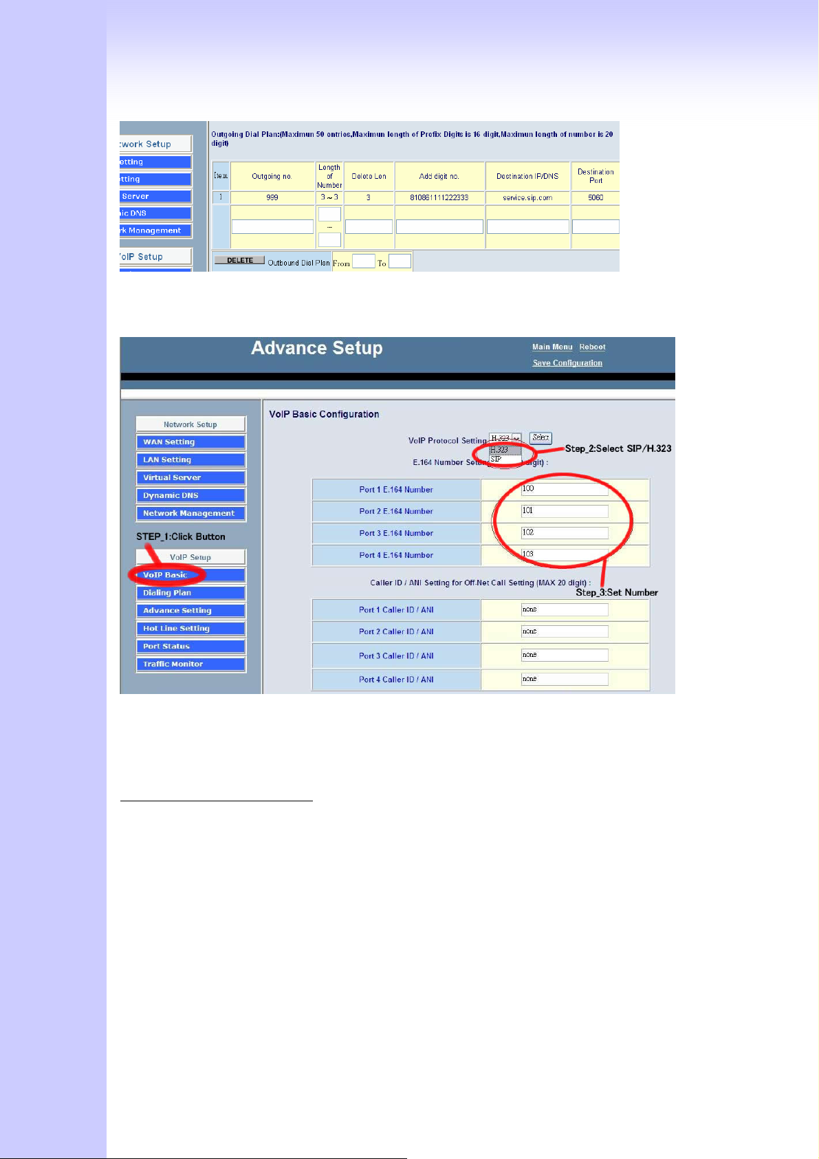
The destination IP address is the domain name of sip proxy serve
1. Choose “VoIP Basic”. Login in web interface, and in ”Advance Setting”.
2. Select you wan to use protocol (SIP/H.323).
3. Input you want to use call number.
Setp_2:Setting Dialing plan
59
Page 60
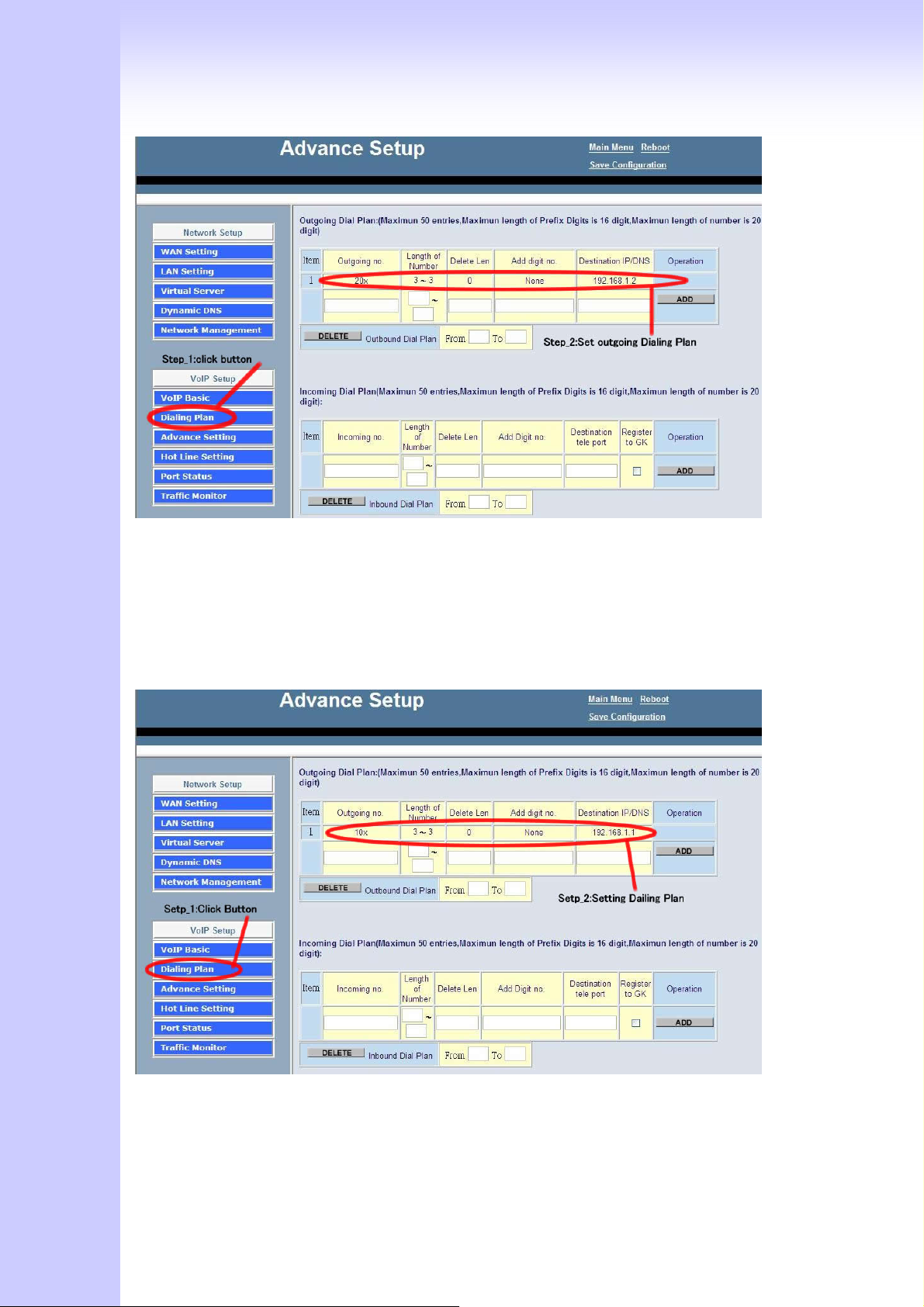
For Gateway_1 Setting
1. Choose “Dialing plan” and Setting Outgoing Dial plan.
2. Setting dial plan just like picture for demo.”20x” the “x” mean wild card , it can be
one of “0~9” number. And length “3~3”, when you input 3 number and the call will
be made. Destination is the Gateway_2 IP address.
For Gateway_2 Setting
1. choose “Dialing plan” and Setting Outgoing Dial plan.
2. Setting dial plan just like picture for demo.”10x” the “x” mean wild card , it can be
one of “0~9” number. And length “3~3”, when you input 3 number and the call will
60
Page 61

be made. Destination is the Gateway_1 IP address.
Step_3:make call each other
1.When you setting 2 gateway done, you can make call by each other. On gateway_1,
just call “200”,and the gateway_2 Port_1 will ringing, then be made a call. And
gateway_2 call “100” , the gateway_1 will ringing, then be made a ca
D Application
61
Page 62
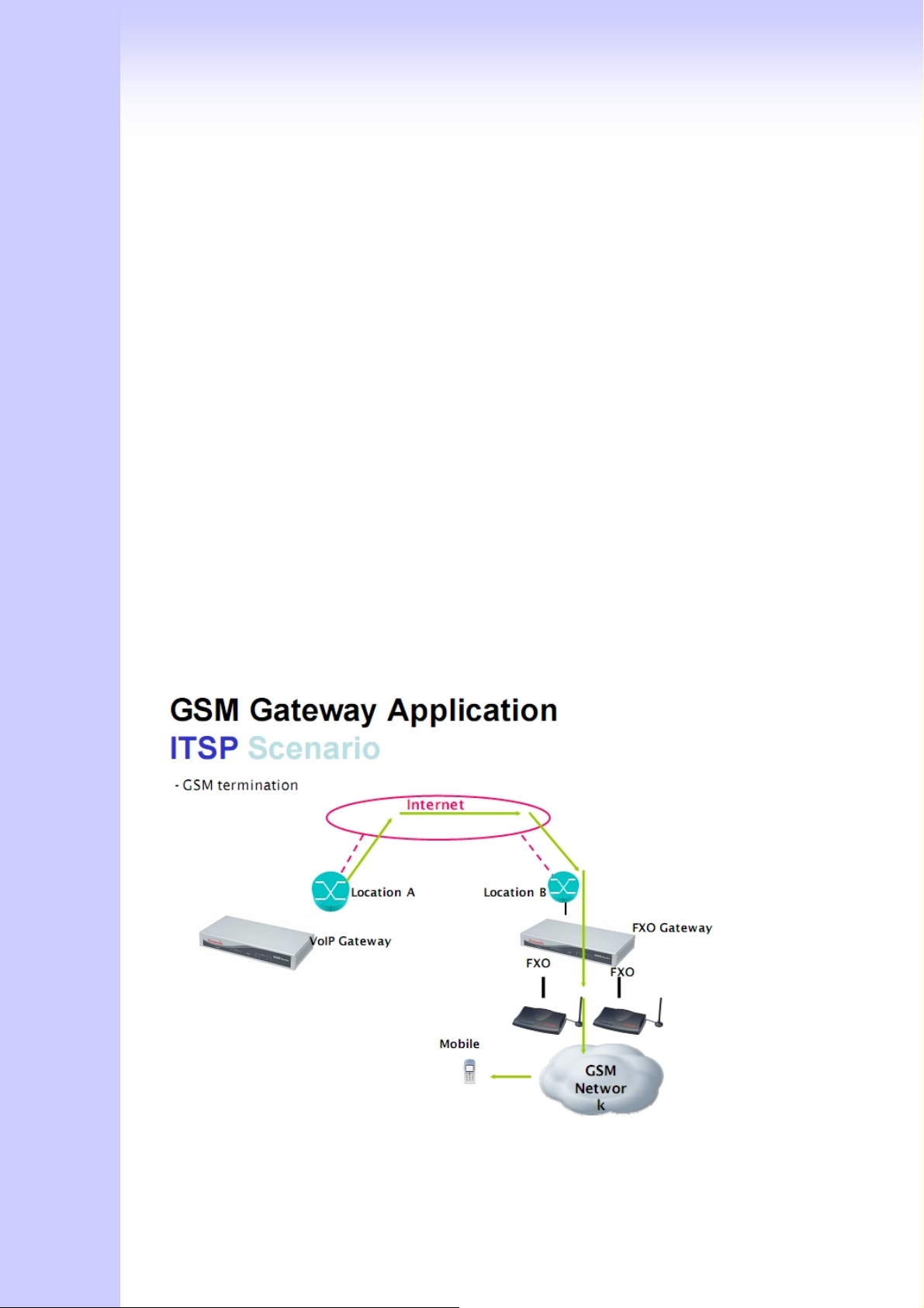
G100
62
Page 63
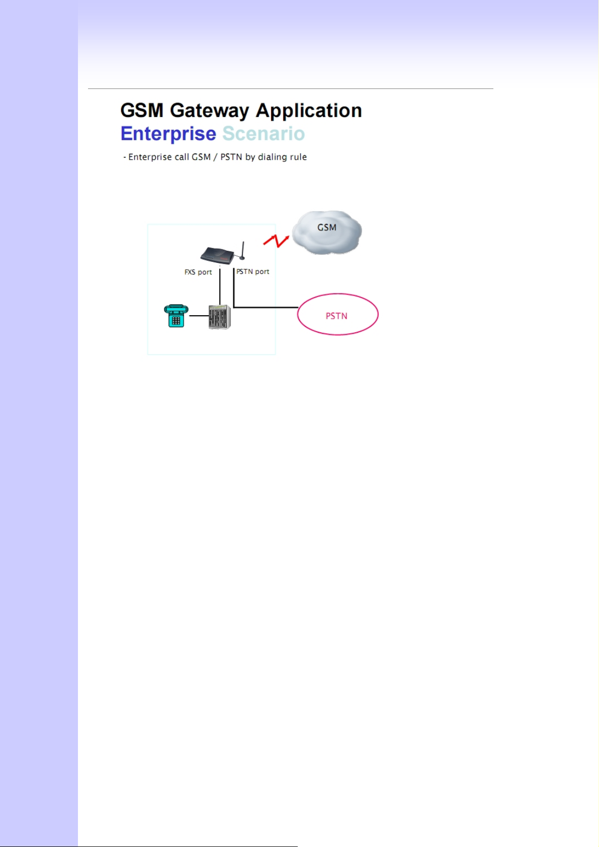
V100
63
Page 64
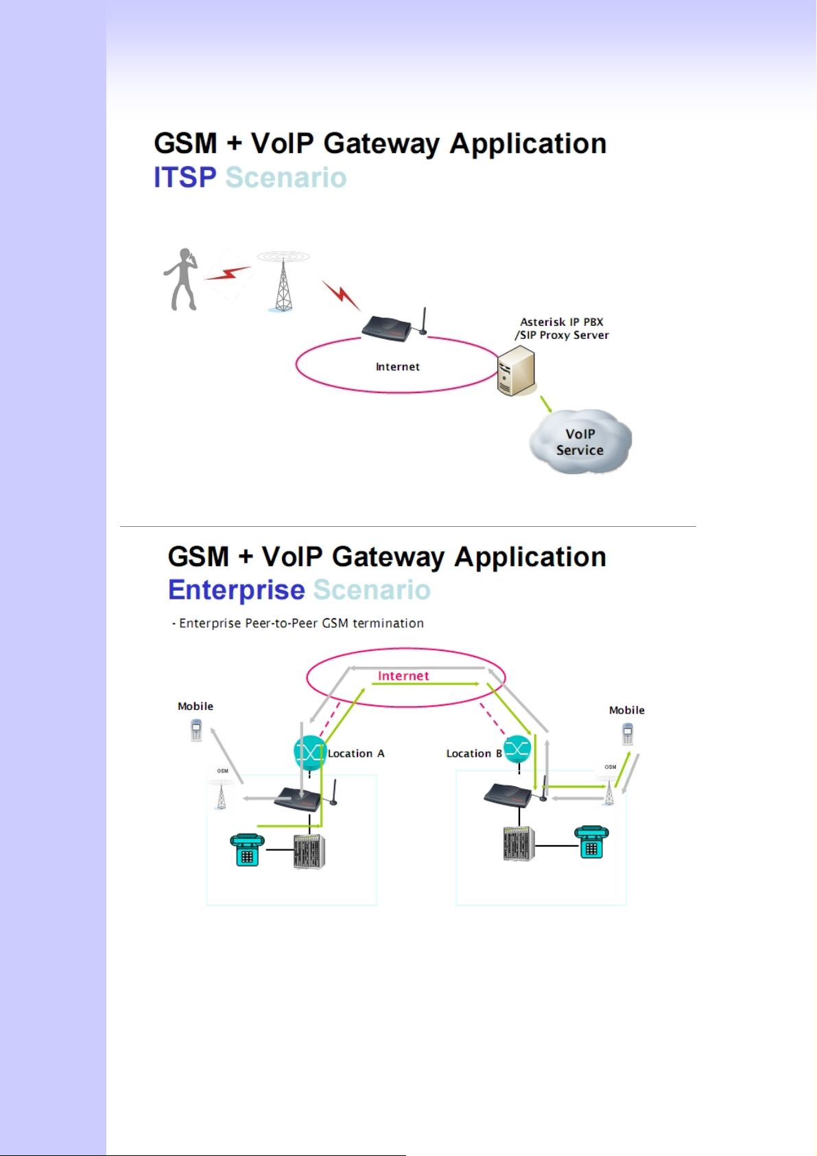
64
Page 65
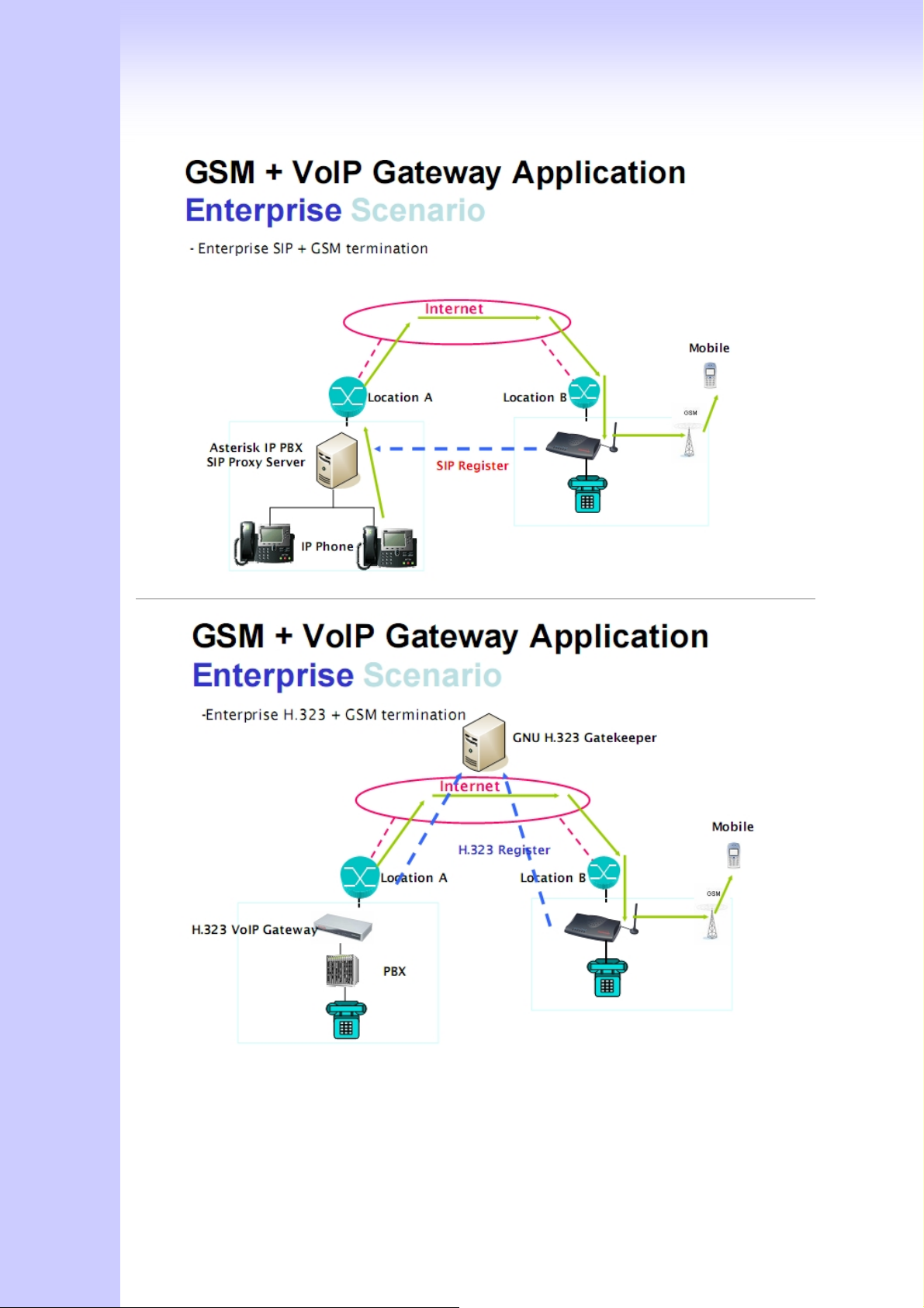
65
Page 66

FCC Notices
This device complies with Part 15 of the FCC Rules. Operation is subject to the condition
that this device does not cause harmful interference.
CAUTION: Change or modification not expressly approved by the party responsible
for compliance could void the user’s authority to operate this equipment.
This equipment has been tested and found to comply with the limits for a Class B
digital device, pursuant to Part 15 of the FCC Rules. These limits are designed to provide
reasonable protection against harmful interference in a residential installation. This
equipment generates, uses and can radiate radio frequency energy and, if not installed
and used in accordance with the instructions, may cause harmful interference to radio
communications. However, there is no guarantee that interference will not occur in a
particular installation. If this equipment does cause harmful interference to radio or
television reception, which can be determined by turning the equipment off and on, the
user is encouraged to try to correct the interference by one or more of the following
measures:
--Reorient or relocate the receiving antenna.
--Increase the separation between the equipment and receiver.
--Connect the equipment into an outlet on a circuit different from that to which the receiver
is connected.
--Consult the dealer or an experienced radio/TV technician for help.
CAUTION:
Any changes or modifications not expressly approved by the grantee of this device could
void the user's authority to operate the equipment.
RF exposure warning
This equipment must be installed and operated in accordance with provided instructions
and the antenna(s) used for this transmitter must be installed to provide a separation
distance of at least 20 cm from all persons and must not be co-located or operating in
conjunction with any other antenna or transmitter. End-users and installers must be
provide with antenna installation instructions and transmitter operating conditions for
satisfying RF exposure compliance."
 Loading...