

Soundwin S1600, S1608, S1616, SB 800, SB 804 User Manual
...
User’s Manual
– Version: 2.33 –

2
Table of Contents
TABLE OF CONTENTS 2
PREFACES 5
0.1 ABOUT THIS MANUAL 5
0.2 COPYRIGHT DECLARATIONS 5
0.3 TRADEMARKS 5
0.4 SAFETY INSTRUCTIONS 5
0.5 WARRANTY 5
INTRODUCE 6
1.1 OVERVIEW 6
1.2 ACRONYMS TABLE 6
1.3 INTRODUCTION 7
1.4 FRONT PANEL LED INDICATORS & REAR PANELS 8
1.4.1 VOIP GATEWAY & SIP PROXY SERVER & GATEKE EPER OUTLOOK 8
1.4.2 FRONT PANEL LED AND CONTAINER DESCRIPTIONS 9
1.4.3 REAR PANEL DESCRIPTIONS 12
1.5 FEATURES AND SPECIFICATIONS 16
1.5.1 VOIP GATEWAY FEATURES 16
1.5.2 H.323 GATEKEEPER FEATURES – EMBEDDED SOFTWARE 17
1.5.3 SIP PROXY SERVER FEATURES – EMBEDDED SOFTWARE 17
1.5.4 VOIP GATEWAY & EMBEDDED H.323 GATEKEEPER & SIP PROXY SERVER SPECIFICATIONS 17
INSTALLATION AND SETUP 19
2.1 PACKAGE CONTENT 19
2.1.1 L200/S200/S400 SERIES GATEWAY & EMBEDDED H.323 GATEKEEPER/ SIP PROXY SERVER20
2.1.2 S800 SERIES GATEWAY & EMBEDDED H.323 GATEKEEPER/ SIP PROXY SERVER 20
2.1.3 SB800/S1600/S2400 SERIES HIGH DENSITY GATEWAY 21
2.1.4 Call manager
21
2.2 INSTALLATION 22
2.3 SETUP 24
2.3.1 FACTORY DEFAULT SETTING 24
2.3.2 CONSOLE 24
2.3.3 TELNET 25
2.3.4 WEB USER INTERFACE 28

3
WIZARD FOR QUICK SETUP 32
3.1 WAN PORT TYPE SETUP 32
3.2 CONFIGURING NAT OR BRIDGE SETTING: 34
3.3 VOIP CALL PROTOCOL SETUP 35
GATEWAY SETTING 36
4.1 NETWORK CONFIGURATION 38
4.1.1 WAN PORT TYPE SETUP 38
4.1.2 CONFIGURING LAN IP ADDRESS AND DHCP SERVER 40
4.1.3 VIRTUAL SERVER SETUP 41
4.1.4 DYNAMIC DNS 41
4.1.5 NETWORK MANAGEMENT 42
4.2 VOIP SETUP 43
4.2.1 H.323 SETUP 43
4.2.2 SIP SETUP 51
4.2.3 DIRECT CALL (PEER TO PEER) SETUP 57
4.2.4 OTHER VOIP SETTING 60
4.3 SIP PROXY SERVER (SVR) SETUP 62
4.4 H.323 GATEKEEPER (GK) SETUP 67
4.5
CALL MANAGER SETUP 70
4.6
SYSTEM ADMINISTRATOR 71
4.6.1 SAVE CONFIGURATION AND REBOOT 71
4.6.2 ACCESS CONTROL 71
4.6.3 SET TO DEFAULT CONFIGURATION 72
4.6.4 BACKUP/RESTORE CONFIGURATION TO A FILE 72
4.6.5 SYSTEM INFORMATION DISPLAY FUNCTION 73
4.6.6 SNTP SETTING FUNCTION 73
4.6.7 CAPTURE PACKETS FUNCTION 74
4.7 UPDATE FIRMWARE(FOR GATEWAY & GK & SVR) 75
APPENDIX 78
A FAQ LIST 78
B SIP SETTING VOIPBUSTER 80
C ANSWER SUPERVISION 82
D SIP SPEEDS CALL 84
E INTEROPERABILITY LIST 86
F RJ21 (TELCO 50) CABLE AND PATCH PANEL INSTALL 87
G SB800 / S1600 / S2400 SERIES MODULE EXTENSION INSTALL 88
H GATEWAY VALUE SETTING 92
I SCENARIO APPLICATION SAMPLES 93

4
J FXO ANSWER MODE 96

5
PREFACES
0.1 About This Manual
This manual is designed to assist users in using VoIP Gateway and Call Manager. Information
in this document has been carefully checked for accuracy; however, no guarantee is given as to
the correctness of the contents. The information contained in this document is subject to change
without notice.
0.2 Copyright Declarations
Copyright 2006 Telephony Corporation. All rights reserved. This publication contains
information that is protected by copyright. No part may be reproduced, transmitted, transcribed,
stored in a retrieval system, or translated into any language without written permission from the
copyright holders.
0.3 Trademarks
Products and Corporate names appearing in this manual may or not be registered trade
marks or copyrights of their respective companies, and are used only for identification or
explanation and to the owners’ benefit, without to infringe.
0.4 Safety Instructions
The most careful attention has been devoted to quality standards in the manufacture of the
Gateway. Safety is a major factor in the design of every set. But, safety is your responsibility too.
Use only the required power voltage. Power Input: AC 100-240V, 50-60Hz
To reduce the risk of electric shock, do not disassemble this product. Opening
or removing covers may expose the Gateway to hazardous voltages. Incorrect
reassembly can cause electric shock when this product is subsequently used.
Never push objects of any kind into the equipment through housing slots since
they may touch hazardous voltage points or short out parts those could result
in a risk of electric shock. Never spill liquid of any kind on the product. If liquid
is spilled, please refer to the proper service personnel.
Use only Unshielded Twisted Pair (UTP) Category 5 Ethernet cable to RJ-45
port of the Gateway.
0.5 Warranty
We warrant to the original end user (purchaser) that the S series gateways will be free from any
defects in workmanship or materials for a period of one (1) years from the date of purchase from
the dealer. Please keep your purchase receipt in a safe place as it serves as proof of date of
purchase. During the warranty period, and upon proof of purchase, should the product have
indications of failure due to faulty workmanship and/or materials, we will, at our discretion, repair
or replace the defective products or components, without charge for either parts or labor, to
whatever extent we deem necessary to re-store the product to proper operating condition. Any
replacement will consist of a new or re-manufactured functionally equivalent product of equal
value, and will be offered solely at our discretion. This warranty will not apply if the product is
modified, misused, tampered with, damaged by an act of God, or subjected to abnormal working
conditions. The warranty does not cover the bundled or licensed software of other vendors.
Defects which do not significantly affect the usability of the product will not be covered by the
6
warranty. We reserve the right to revise the manual and online documentation and to make
changes from time to time in the contents hereof without obligation to notify any person of such
revision or changes.
Note
Repair or replacement, as provided under this warranty, is the exclusive remedy of the
purchaser. This warranty is in lieu of all other warranties, express or implied, including any
implied warranty of merchantability or fitness for a particular use or purpose. We shall in no
event be held liable for indirect or consequential damages of any kind of character to the
purchaser.
To obtain the services of this warranty, contact us for your Return Material Authorization
number (RMA). Products must be returned Postage Prepaid. It is recommended that the unit
be insured when shipped. Any returned products without proof of purchase or those with an
out-dated warranty will be repaired or replaced and the customer will be billed for parts and
labor. All repaired or replaced products will be shipped by us to the corresponding return
address, Postage Paid. This warranty gives you specific legal rights, and you may also have
other rights that vary from country to country.
Introduce
L / S series VoIP Gateway and Call Manager are the low to high VoIP total Solutions. This
document describes the usage of Voice gateway and Call Manager.
1.1 Overview
VoIP Gateway which is a device that allows one to connect a normal PSTN telephone to the
Internet in order to make or place telephone calls.
VoIP Gateway device may work in conjunction with a computer, such as an IP-sharing /
Router, or it may be a stand-alone device that communicates with a service provider over the
Internet.
VoIP Gateway provides a direct analog interface for computer modems, fax machines, analog
telephones, and other devices that require an analog port.
2/4/8 port Series VoIP Gateway can build in a simple H.323 Gatekeeper or SIP Proxy Server.
VoIP Gateway also support standard Internet services, such as IP-Sharing, NAT, Virtual
Server, DDNS, QOS, Port Filter, IP Filter function.
1.2 Acronyms Table
Acronym: Full Name: Acronym: Full Name:
ADC Analog to Digital Converter CODEC Coder / Decoder
DAC Digital to Analog Converter DC Direct Current
DDNS Dynamic Domain Name System DHCP Dynamic Host Configuration
Protocol
DMZ Demilitarized Zone DNS Domain Name System
DTMF Dual Tone Multi Frequency FXO Foreign Exchange Office
FXS Foreign Exchange Station GMT Greenwich Mean Time
IP Internet Protocol IPsec Internet Protocol Security
L2TP The Layer 2 Tunnel Protocol LAN Local Area Network
WAN Wide Area Network MAC Media Access Control
MII Media Independent Interface NAT Network Address Translation
NTP Network Time Protocol PPTP Point-to-Point Tunneling Protocol
RTP Real-Time Transport Protocol RTCP Real-Time Transport Control
Protocol (also known as RTP

7
control protocol)
SIP Session Initiation Protocol SLIC Subscriber Line Interface Circuit
STUN Simple Traversal of UDP through
NATs
URI Uniform Resource Identifier
TCP Transmission Control Protocol UDP User Datagram Protocol
UPnP Universal Plug and Play VoIP Voice Over Internet Protocol
1.3 Introduction
This VoIP Gateway provides a total solution for integrating voice-data network and PSTN.
The L200 and S series gateway is low to high density port gateway which support SIP / H.323
VoIP Protocol. Low model (2/4 port) can embedded H.323 Gatekeeper or SIP Proxy Server
(Option). The L200 and S series gateway
allows 2 ~ 24 lines (model option) analog voice and
fax communication over a traditional data communications/data networking digital Internet. There
are 6 model compare table follow.
Model Compare Table
Model
FXO Port FXS Port LAN Port WAN Port
LCD
Display
RS-232
port
SIP H.323
H.323 Gatekeeper
/ SIP proxy Server
(Software embedded)
S2400 Series ( 24 analog lines)
S2400
0 24 1 1
√ √ √ √
S2412
12 12 1 1
√ √ √ √
S2424
24 0 1 1
√ √ √ √
S1600 Series ( 16 analog lines )
S1600
0 16 1 1
√ √ √ √
S1608
8 8 1 1
√ √ √ √
S1616
16 0 1 1
√ √ √ √
SB800 Series ( 8 analog lines )
SB 800
0 8 1 1
√ √ √ √
SB 804
4 4 1 1
√ √ √ √
SB 808
8 0 1 1
√ √ √ √
S800 Series( 8 analog lines Gateways /Embedded H.323 Gatekeepers/Embedded Sip Proxy Serves)
S800
0 8 1 1
√ √ √
SK800/SVR800
S802
2 6 1 1
√ √ √
SK802/SVR802
S804
4 4 1 1
√ √ √
SK804/SVR804
S808
8 0 1 1
√ √ √
SK808/SVR808
S400 Series ( 4 analog lines Gateways/embedded Gatekeepers/Sip Proxy Servers)
S400
0 4 4 1
√ √
SK400/SVR400
S401
1 3 4 1
√ √
SK401/SVR401
S402
2 2 4 1
√ √
SK402/SVR402
S404
4 0 4 1
√ √
SK404/SVR404

8
S200 Series ( 2 analog lines gateways/ Embedded H.323 Gatekeepers/ Embedded Sip Proxy Servers)
S200
0 2 4 1
√ √
SK200/SVR200
S201
1 1 4 1
√ √
SK201/SVR201
S202
2 0 4 1
√ √
SK202/SVR202
L200 Series ( 2 analog lines Gateways/embedded Gatekeepers/Sip Proxy Servers)
L200
0 2 1 1
√ √
LK200/LVR200
L201
1 1 1 1
√ √
LK201/LVR201
L202(*)
2 0 1 1
√ √
LK202/LVR202(*)
Call Manager
C400
4 0 4 1
√ √
* : manufacture by order (lead time : 60 days)
1.4 Front Panel LED Indicators & Rear Panels
1.4.1 Gateway & Embedded Sip proxy server & Embedded H.323 Gatekeeper
Outlook
S200/S400 Series & C400 Call Manager:
S200/S400 VoIP Gateway
SK200 /SK400 VoIP Gateway building in H.323 Gatekeeper Software
SVR200/SVR400 VoIP Gateway building in SIP Proxy Server Software
C400 Call Manager
S800 Series & C800 Call Manager:
-S800 VoIP Gateway
-SK800 VoIP Gateway building H.323 Gatekeeper Software
-SVR800 VoIP Gateway building SIP Proxy Server Software
-C800 Call Manager
S1600 / S2400 Series:
SB800/S1600/S400 VoIP Gateway
9
L200 Series:
-L200 Series Gateway
-LK200 Series Gateway building in H.323 Gatekeeper Software
-LVR200 Series Gateway building in SIP Proxy Server Software
1.4.2 Front Panel LED and Container Descriptions
L200(GW/GK/SVR) Series
-----------------------------------------------------------------------------------LED State Description
------------------------------------------------------------------------------------
1. POWER On ATA is power ON
Off ATA is power Off
-------------------------------------------------------------------------------------
2. WAN port On ATA network connection established
Flashing Data traffic on cable network
Off Waiting for network connection
-------------------------------------------------------------------------------------
3. LAN port On LAN is connected successfully
Flashing Data is transmitting
Off Ethernet not connected to PC
-------------------------------------------------------------------------------------
4. FXS Off Telephone Set is On-Hook
Flashing Ring Indication
On Telephone Set is Off-Hook
-------------------------------------------------------------------------------------
5. FXO Off Line is On-hook
On Line is In-Use
-------------------------------------------------------------------------------------
S200/S400(GW/GK/SVR) Series & C400 Call Manager

10
-----------------------------------------------------------------------------------LED State Description
------------------------------------------------------------------------------------
1. POWER On GW is power ON
Off GW is power Off
-------------------------------------------------------------------------------------
2. WAN port On GW network connection established
Flashing Data traffic on cable network
Off Waiting for network connection
-------------------------------------------------------------------------------------
3. LAN port On LAN is connected successfully
Flashing Data is transmitting
Off Ethernet not connected to PC
-------------------------------------------------------------------------------------
4. FXS(Port) Off Telephone Set is On-Hook
Flashing Ring Indication
On Telephone Set is Off-Hook
-------------------------------------------------------------------------------------
5. FXO(Port) Off Line is not enabled
On Line is busy
NOTE: System initialization will turn some LEDs ON for a few sec.
When System Boot/Reboot , the Port LEDs will flash in turn for a few sec.
S800 (GW/GK/SVR) Series & C800 Call Manager
-----------------------------------------------------------------------------------------LED State Description
------------------------------------------------------------------------------------------
1. POWER On GW is power ON
Off GW is power Off
------------------------------------------------------------------------------------------
2. RUN port On GW connection established
Flashing Data traffic on cable network
Off Waiting for GW connection
------------------------------------------------------------------------------------------
3. WAN port 100M
On GW network connection 100MB network
Off GW network connection 10MB network
ACT
ON GW network connection established
Flashing Data traffic on cable network
Off Waiting for network connection
------------------------------------------------------------------------------------------
4. LAN port 100M
On GW LAN connection 100MB network
Off GW LAN connection 10MB network

11
ACT
On LAN is connected successfully
Flashing Data is transmitting
Off Ethernet not connected to PC
-------------------------------------------------------------------------------------
5. FXS(Port) Off Telephone Set is On-Hook
Flashing Ring Indication
On Telephone Set is Off-Hook
-------------------------------------------------------------------------------------
6. FXO(Port) Off Line is not enabled
On Line is busy
-------------------------------------------------------------------------------------
7. RES Button Push Push Button until 5 second
Set to Factory Default
-------------------------------------------------------------------------------------
8. RS-232 Console port connect to PC
NOTE: System initialization will turn some LEDs ON for a few sec.
When System Boot/Reboot , the Port LEDs will flash in turn for a few sec.
SB800/S1600/S2400 Series Gateway
-----------------------------------------------------------------------------------------LED State Description
------------------------------------------------------------------------------------------
1. POWER On GW is power ON
Off GW is power Off
------------------------------------------------------------------------------------------
2. RUN port On GW connection established
Flashing Data traffic on cable network
Off Waiting for GW connection
------------------------------------------------------------------------------------------
3. WAN port 100M
On GW network connection 100MB network
Off GW network connection 10MB network
ACT
ON GW network connection established
Flashing Data traffic on cable network
Off Waiting for network connection
------------------------------------------------------------------------------------------
4. LAN port 100M
On GW LAN connection 100MB network
Off GW LAN connection 10MB network
ACT
On LAN is connected successfully
Flashing Data is transmitting
Off Ethernet not connected to PC
-------------------------------------------------------------------------------------
5. FXS(Port) Off Telephone Set is On-Hook
12
Flashing Ring Indication
On Telephone Set is Off-Hook
-------------------------------------------------------------------------------------
6. FXO(Port) Off Line is not enabled
On Line is busy
-------------------------------------------------------------------------------------
6. LCD Panel Off System is Shutdown
On System is Up
NOTE: System initialization will turn some LEDs ON for a few sec.
When System Boot/Reboot , the Port LEDs will flash in turn for a few sec.
1.4.3 Rear Panel Descriptions
L200(GW/GK/SVR) Series
Item Port Description
1 FXS(Foreign Exchange Station) FXS port can be connected to analog telephone sets
or Trunk Line of PBX.
2 FXO(Foreign Exchange Office) Can be Connected to PBX or CO line with RJ-11
analog line. FXO port can be connected to the
extension port of a PBX or directly connected to a
PSTN line of carrier.
3 WAN(Wide Area Network) Connect to the network with an Ethernet cable. This
port allows your ATA to be connected to an Internet
Access device, e.g. router, cable modem, ADSL
modem, through a networking cable with RJ-45
connectors used on 10BaseT and 100BaseTX
networks.
4 LAN(Local Area Network) Connect to PC with Ethernet cable. 1 port allows your
PC or Switch/Hub to be connected to the ATA
through a networking cable with RJ-45 connectors
used on 10BaseT and 100BaseTX networks.
5 RES(Reset button) Push this button until 3 seconds, and ATA will be set
to factory default configuration.
6 AC power(DC in 12V) A power supply cable is inserted

13
S200/S400(GW/GK/SVR) Series & C400 Call Manager
Item Port Description
1 FXS(Foreign Exchange Station) Connect to Phone with RJ-11 (Black) analog line.
FXS port was connected to your telephone sets, FAX,
or Trunk Line of PBX.
2 FXO(Foreign Exchange Office) Connect to PBX or CO line with RJ-11(Write) analog
line. FXO port was connected to the extension port of
a PBX or directly connected to a PSTN line of carrier.
3 WAN(Wide Area Network) Connect to the network with an Ethernet cable. This
port allows your GW to be connected to an Internet
Access device, e.g. router, cable modem, ADSL
modem, through a networking cable with RJ-45
connectors used on 10BaseT and 100BaseTX
networks.
4 LAN(Local Area Network) Connect to PC with Ethernet cable. 4 ports allow your
PC or Switch/Hub to be connected to the GW through
a networking cable with RJ-45 connectors used on
10BaseT and 100BaseTX networks.
5 RES(Reset button) The reset button, when pressed, resets the cable
voice gateway without the need to unplug the power
cord.
Push this button until 5 seconds, and GW will be set
to factory default.
6 AC power(DC in 12V) A power supply cable is inserted.
The supplied power adapter converts
110V or 220V AC to DC as required for this device.
*there is no FXO port in Call Manager

14
S800 (GW/GK/SVR) Series & C800 Call Manager
Item Port Description
1 FXS(Foreign Exchange Station) Connect to Phone with RJ-11 (Black) analog line.
FXS port was connected to your telephone sets, FAX,
or Trunk Line of PBX.
2 FXO(Foreign Exchange Office) Connect to PBX or CO line with RJ-11(Write) analog
line. FXO port was connected to the extension port of
a PBX or directly connected to a PSTN line of carrier.
3 WAN(Wide Area Network) Connect to the network with an Ethernet cable. This
port allows your GW to be connected to an Internet
Access device, e.g. router, cable modem, ADSL
modem, through a networking cable with RJ-45
connectors used on 10BaseT and 100BaseTX
networks.
4 LAN(Local Area Network) Connect to PC with Ethernet cable. 1 port allow your
PC or Switch/Hub to be connected to the GW through
a networking cable with RJ-45 connectors used on
10BaseT and 100BaseTX networks.
5. Switch power Power Switch, turn on/off the GW power supplied. [I]
is turn on the power, and [o] is turn off the power.
6 AC power(DC in 12V) A power supply cable is inserted.
The supplied power adapter converts
110V or 220V AC to DC as required for this device.
7 RS-232 RS-232 console port connect to PC, Use Pc com port
to connect RS-232 console , setting GW configure.
8 RES(Reset button) The reset button, when pressed, resets the cable
voice gateway without the need to unplug the power
cord.
Push this button until 5 seconds, and GW will be set
to factory default.
*there is no FXO port in Call Manager
15
SB800/S1600/S2400 Series Gateway
Item Port Description
1 Standard Telco 50 PIN
Connector (RJ-21)
It is a 50 pins RJ-21 connector for connecting to
telephone patch pane
2 RES(Reset button) The reset button, when pressed, resets the cable
voice gateway without the need to unplug the power
cord.
Push this button until 5 seconds, and GW will be set
to factory default.
3 RS-232 RS-232 console port connect to PC, Use Pc com port
to connect RS-232 console , setting GW configure.
4 WAN(Wide Area Network) Connect to the network with an Ethernet cable. This
port allows your GW to be connected to an Internet
Access device, e.g. router, cable modem, ADSL
modem, through a networking cable with RJ-45
connectors used on 10BaseT and 100BaseTX
networks.
5. LAN(Local Area Network) Connect to PC with Ethernet cable. 1 port allow your
PC or Switch/Hub to be connected to the GW through
a networking cable with RJ-45 connectors used on
10BaseT and 100BaseTX networks.
6 Switch power Power Switch, turn on/off the GW power supplied. [I]
is turn on the power, and [o] is turn off the power.
7 AC power(DC in 12V) A power supply cable is inserted.
The supplied power adapter converts
110V or 220V AC to DC as required for this device.
8 LCD Panel Setting GW and view GW status, use [up/down]
button to select Menu, and [menu] button return to
main and click select.

16
1.5 Features and Specifications
The L200 and S Series Gateways provide many built-in server and software features to
provide a convenient comprehensive solution for your VoIP network
1.5.1 Gateway Features
VoIP Key Features
Both support SIP and H.323 protocols: SIP Registration and Digest Authentication and
H.323 Gatekeeper Registration.
Single Number / Account for multiple ports.
Caller ID Delivery and Detection: FXS support DTMF&FSK Caller ID generation; FXO
supports DTMF&FSK Caller ID detection. (Optional)
Smart VoIP call Dialing Book: VoIP call Book could provide any application VoIP call to any
type destination (Domain name / IP address, PSTN or PBX) or hunting number setting.
AC termination Impedance : 600/900 OHM and complex impedance
Answer Supervision for Polarity Reversal Detection and Voice detection
NAT traversal: This feature allow gateway to operate behind any NAT/Firewall device. There
is no need to change any configuration of NAT/Firewall like setting virtual server.
Smart-QoS: This feature provides good voice quality when user place a VoIP call and access
internet at the same time. The gateway will automatically start to reserve bandwidth for voice
traffic when VoIP call proceeds.
Call Hunting Facility: This function helps gateway to use the lines effectively. This facility
automatically transfers your incoming call to a free line. Subscribers need not indicate
numerous numbers of each port of gateway.
Voice channels status display: This function display each port status like as on-hook, off-hook,
calling number callee’s number, talk duration, codec.
Pulse Dial support: Support pulse dialing generation and detection. (Optional)
Flash Detection and Generation Program: FXO support Flash Generation and FXS support
Flash Detection.
CDR: Use Syslog Server to receive CDR information that gateway send by UDP.
Modules Card Extension: Extension FXO/FXO Modules card upgrade gateway port max to 24
port.(SB800/S1600/S2400)
Embedded H.323 Gatekeeper (GK) / SIP Proxy Server (SVR): For 2/4/8 port gateway can
embedded GK/SVR function. A simple H.323 GK / SIP proxy with gateway at the same
device. Support standard Registered and call Sever Function.(Option)
Call Features
Voice channels status display
Direct Dialing Mode : peer to peer call (support IP Address Call or Domain Name Call)
Register Call Mode : register to SIP Proxy Server or H.323 Gatekeeper
Adjustable volume : - 9 db ~ 9 db
Silence Compression(VAD)
Auto Dial for speed
Dynamic Jitter Buffer
Hot-Line Support(PLAR)
Configuration & Management
Web-based Graphical User Interface
RS232 for configuration(S800/S1600/S2400)
Remote management over the IP Network
FTP firmware upgrade
Backup and Restore Configuration file
Front LCD Panel for System Status and Management(SB800/S1600/S2400)
Syslog support

17
1.5.2 Embedded H.323 Gatekeeper Features
200 H.3232 endpoints scale: SK400 providing 250 H.323 endpoints to register.
Register Security Policy: SK400 providing security setting on your H.323 VoIP network. This
provides protection for VoIP calls and insures proper endpoint identification.
Pre-Granted Endpoints: letting other gateways or H.323 endpoints which were not register to
this embedded gatekeeper. And the registered VoIP Gateways can make an Off-Net call to
these pre-granted endpoints..
Real time Call Detail Record and Post Call Detail Record Report : Support Real Time CDR to
monitor VoIP calls, including caller ip, called ip , call date , call duration and other information.
Also providing a CDR report to look up VoIP call record.
Top 20 list: SK400 Gatekeeper can lists top 20 calls by call duration, caller number, calling
number, caller IP or callee IP address.
Syslog Client: Providing CDR information to Syslog Server.
1.5.3 Embedded Sip Proxy Features
200 SIP endpoints scale: SVR200 / SVR400 /SVR800 series providing 200 SIP endpoints to
register.
Trunk Line Setting for Off-Net Call: SVR400 / SVR 200 /SVR 800 series providing trunk
interface for Off-Net call by ITSP. (Optional)
Register Security Policy: SVR200 / SVR400 / SVR800 series providing MD5 authentication
setting.
Real time Call Detail Record and Post Call Detail Record Report : Support Real Time CDR to
monitor VoIP calls, including caller ip, called ip , call date , call duration and other information.
Also providing a CDR report to look up VoIP call record.
Top 20 list: SVR200 / SVR 400 / SVR800 series can lists top 20 calls by call duration, caller
number, calling number, caller IP or called IP address.
Syslog client: Send CDR information to Syslog server.
1.5.4 Gateway & Gatekeeper & Sip proxy server Specifications
S200/S400/S800 Series Gateway & Gatekeeper & Sip proxy server & Call Manager
Telephony Specification:
Voice Codec:
G.711(A-law /μ-law), G.729 AB,
G.723 (6.3 Kbps / 5.3Kbps).
FAX support : T.30 / T.38.
Echo Cancellation: G.165/G168(Version:2000).
FXO Caller ID detection : DTMF and FSK (Optional).
FXO hang up detection / anti-seized : Tone Learning Automatically / Manual Tone
Learning (Optional).
Answer supervision: Support Battery Reverse Detection and Voice
Detection.
FXO answer delay time: Support delay 0 – 8000 ms to answer.
Adjustable AC Termination Impedance : 600 / 900 OHM and complex Impedance.
Failsafe Mechanism (FXS relay to FXO) : Power failed by pass support / Internet Failed by
pass (Optional)).
Creative Metering: 12K Hz and 16K Hz Metering (Customized)
IP Specification:
Protocol: H.323 v2/v3/v4 and SIP (RFC 3261) ,
SDP (RFC 2327), Symmetric RTP,

18
STUN (RFC3489), ENUM (RFC 2916),
RTP Payload for DTMF Digits (RFC2833),
Outbound Proxy Support.
LAN : Support Virtual Server, DHCP Server.
WAN: Support PPPoE client, DHCP client, Fix IP Address,
DDNS client.
Network Address Translation: Providing build-in NAT router function.
Smart QoS: Guarantee the voice bandwidth
TOS: IP TOS (IP Precedence) / DiffServ
General Specification
AC power : AC100V-240V, DC12V/1.5A,50/60 Hz
Temperature: 0°C ~ 40°C (Operation)
Humidity: up to 90% non-condensing
Emission: FCC Part 15 Class B, CE Mark
Dimension : IU-440 x 250 x 45 mm(SB800/S1600/S2400)
260 x 130 x 35 mm(S800/GK/SVR)
260 x 130 x 35 mm(S200/S400/GK/SVR)
Weight: 5200 g(SB800/S1600/S2400)
1500g (Aluminum)(S800/GK/SVR)
00g (Aluminum )(S200/S400/GK/SVR)
Others: Standard 50 pin RJ-21 Telco connectors
(SB800/S1600/S2400)
SB800/S1600/S2400 Series gateway can be extension. Combination different modules
card, you can change/upgrade your gateway FXS/FXO ports. Max Up to 24 ports.
Modules Card Table (SB800/S1600/S2400 Only)
Mother Board Description and Function
SB800
Mother Board with 8 FXS Interface
SB804
Mother Board with 4 FXS + 4 FXO Interface
SB808
Mother Board with 8 FXO Interface
Modules Card Description and Function
SM800
8 FXS Interface Module
SM804
4 FXS + 4 FXO Interface Module
SM808
8 FXO Interface Module
19
Installation and Setup
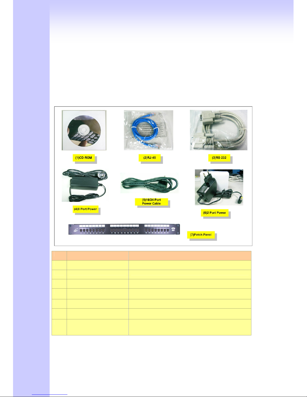
2.1 Package Content
Please check enclosed product and its accessories before installation. (Refer to the item
number). These contents are from pre-released product. The contents for the final product might
change a little bit.
Appurtenances:
Item Appurtenances Description
1 CD-ROM CD Include in all product user manual and datasheet.
2 RJ-45 cable Internet cable RJ-45 connect to NIC/Gateway/Router
3 RS-232 cable RS - 232 Console port connect to PC COM port.
4 Power supply & cable(8) Power Supply,input:100-240V output:+12V
(Europe/UK/US)
5 Power cable(16/24) Power Supply cable.
6 Power supply & cable(2/4) Power Supply,input:100-240V output:+12V
(Europe/UK/US)
7 25 port Telephone
Patch Panel and Cable
(Optional).
For 16/24 port telephone interface Patch Panel .
20
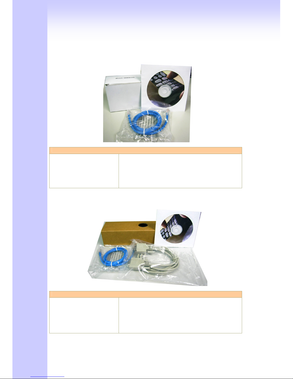
2.1.1 L200 /S200/S400 Series Gateway & embedded Gatekeeper/ Sip Proxy
Server
The 2/4 Port packet contents:
GW,GK,SVR(S200/ S400 Series)
RJ-45
AC Power Adapter
CD-Rom(User manual)
X1
X1
X1
X1
2.1.2 S800 Series Gateway & embedded Gatekeeper/ Sip Proxy Server
The 8 Port packet contents:
GW,GK,SVR(S800 Series)
RJ-45
RS-232
AC Power Adapter
CD-Rom(User manual)
X1
X1
X1
X1
X1
21
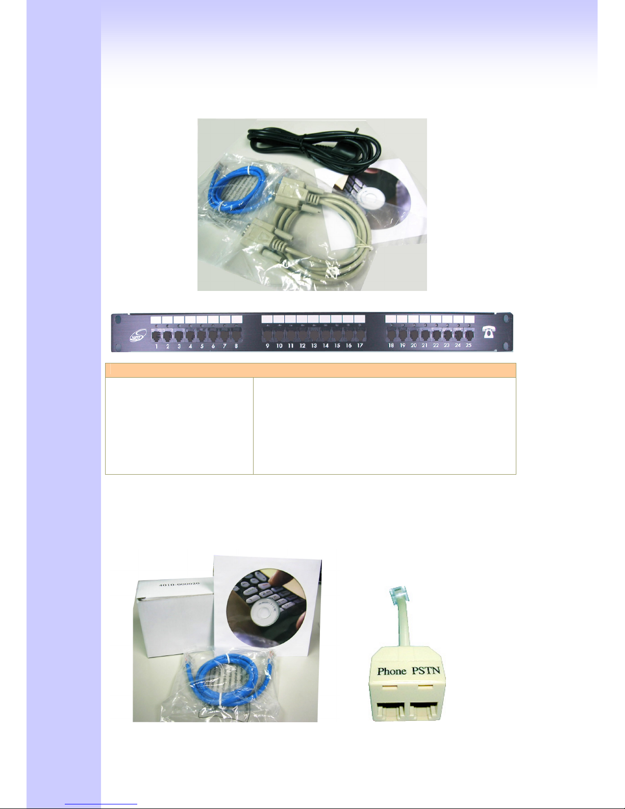
2.1.3 SB800/S1600/S2400 Series High Density Gateway
Patch Panel:
The 8/16/24 Port packet contents:
Gateway
(SB800/S1600/S2400 Series)
RJ-45
RS-232
AC Power Cable
CD-Rom(User manual)
Patch Panel(Option)
X1
X1
X1
X1
X1
2.1.4 C400 Call Manager

22
Call Manager contents:
Call Manager(C400/C800)
RJ-45
RS-232(only C800)
AC Power Adapter
CD-Rom(User manual)
Modular Duplex Jack Extension Cord
X1
X1
(X1)
X1
X1
X4 (C400)
X8 (C800)
2.2 Installation
Install Gateway
1 Connect the 12V DC IN to the power outlet with power adaptor.
2 Connect FXO to PSTN / PBX Extension Line.
3 Connect FXS to a telephone jack with the RJ-11 analog cable (Phone / PBX Trunk Line.)
Connecting to a PC:
1 Connect the Ethernet cable (with RJ-45 connector) to any LAN port.
2 Connect the other end of the Ethernet cable to your PC’s installed network interface card (NIC).
3 The LED indicators at both the Ethernet port and the NIC should be ON.
Connecting to an External Ethernet Hub or Switch:
1 Connect the Ethernet cable (with RJ-45 connector) to WAN port.
2 Connect the other end of the Ethernet cable to DSL/Cable modem or the external Ethernet hub
or switch.
3 The LED indicators on both the LAN port and the external Switch.
Port Description
FXS(Foreign Exchange Station) FXS port can be connected to analog telephone sets or Trunk
Line of PBX.
FXO(Foreign Exchange Office) Can be Connected to PBX or CO line with RJ-11 analog line.
FXO port can be connected to the extension port of a PBX or
directly connected to a PSTN line of carrier.
WAN(Wide Area Network) Connect to the network with an Ethernet cable. This port
23
allows your GW to be connected to an Internet Access
device, e.g. router, cable modem, ADSL modem, through a
networking cable with RJ-45 connectors used on 10BaseT
and 100BaseTX networks.
LAN(Local Area Network) Connect to PC with Ethernet cable. 1 port allows your PC or
Switch/Hub to be connected to the GW through a networking
cable with RJ-45 connectors used on 10BaseT and
100BaseTX networks.
RES(Reset button) Push this button until 3 seconds, and GW will be set to
factory default configuration.
AC power(DC in 12V) A power supply cable is inserted
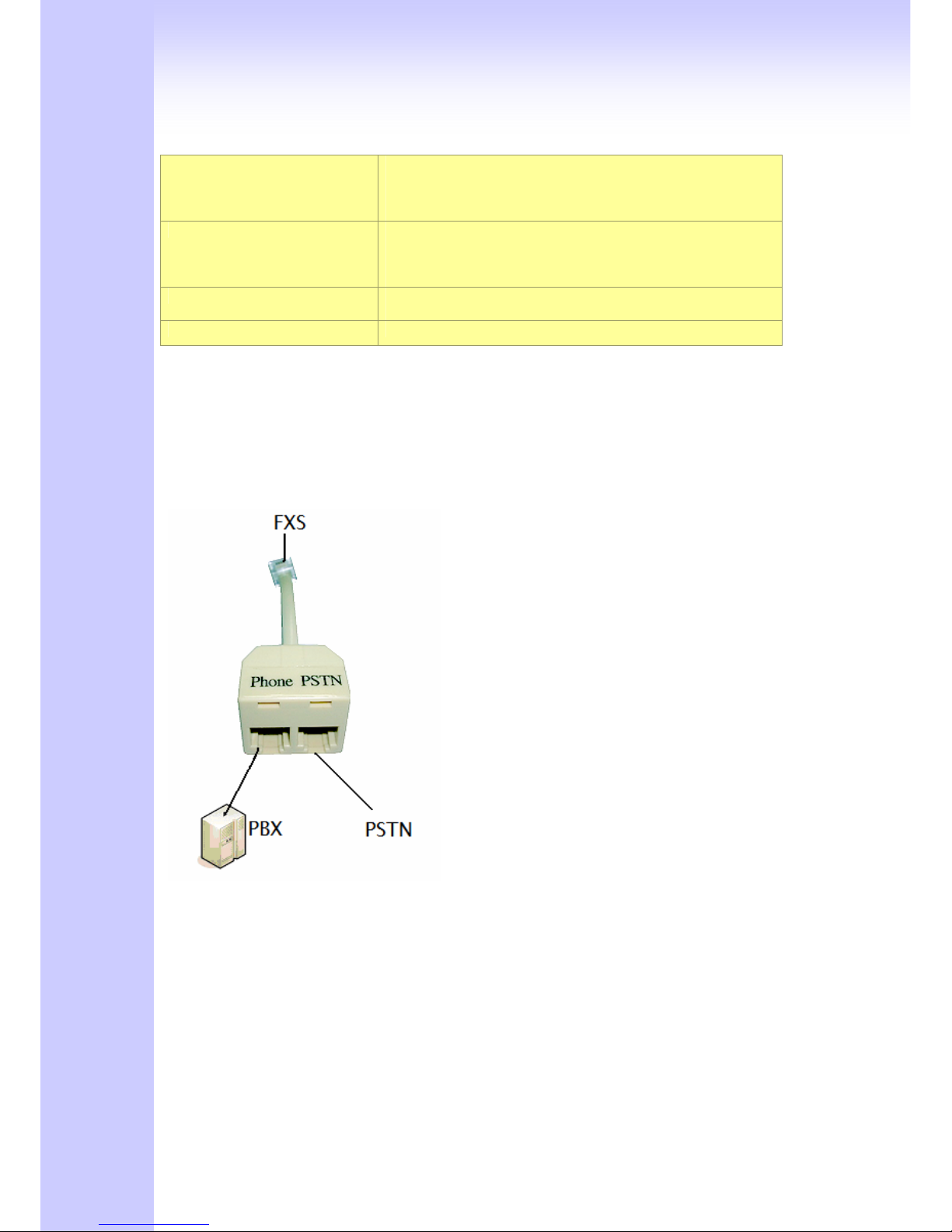
Call Manager ONLY
Connect the cord to FXS port
Connect the PSTN line to PSTN port
Connect the PBX to phone port
The hardware installation is now complete. The following sections will guide you through setting
up your management PC and connecting to the Web User Interface.
24
2.3 Setup
There are 3 way to setting gateway - [Web User Interface] [Telnet] [Console] (Some Series
modules have RS-232 console port like S800/SB800/S1600/S2400).
2.3.1 Factory Default setting
WAN Port IP address : 192.168.1.1
LAN Port IP address : 222.222.222.1
LAN DHCP Server enable IP range: 222.222.222.51 ~ 222.222.222.100
VoIP Number(S200 Series) Port_1~Port_2 number:100,200
VoIP Number(S400 Series) Port_1~Port_4 number:100,200,300,400
VoIP Number(S800 Series) Port_1~Port_8 number:100,200,300,400,500,600,700,800
VoIP Number(SB800 Series) Port_1 ~ Port 8 number : 101~ 108
VoIP Number(S1600 Series) Port_1 ~ Port 16 number: 101~ 116
VoIP Number(S2400 Series) Port_1 ~ Port 24 number: 101~ 124
VoIP default setting was H.323 signal protocol, Direct Mode, Fast-Start and G.723 codec.
Default login authentication username : admin, password : admin
2.3.2 Console
RS-232 port (DB-9pin male connector), Configure the COM Port Properties as following: Bits
per second: 9600, Flow control: None
1. Connect Gateway RS-232 port to PC COM Port.
2. Power on gateway.
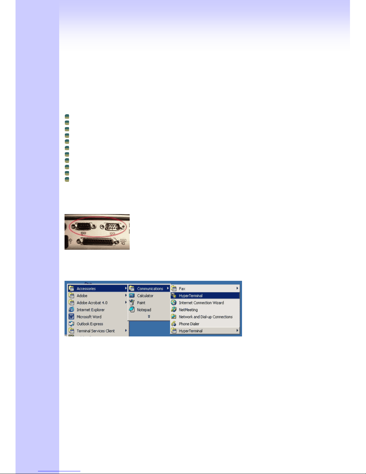
3. Open Terminal Program (ie. Windows XP Hyper Terminal)
[Start] → [Program file] → [Accessories] → [communications] → [Hyper Terminal]
4. Create New connection. Select “Com” port that connect PC to gateway
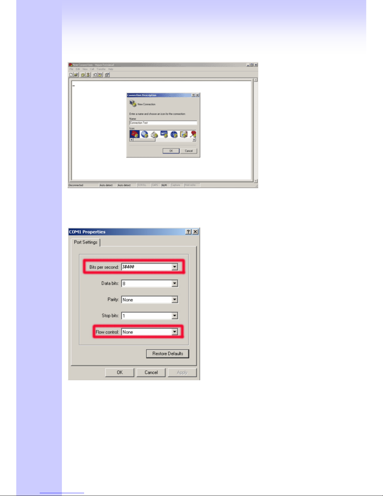
25
5. Make connection(Bits Pre second:38400 Flow contact: None)
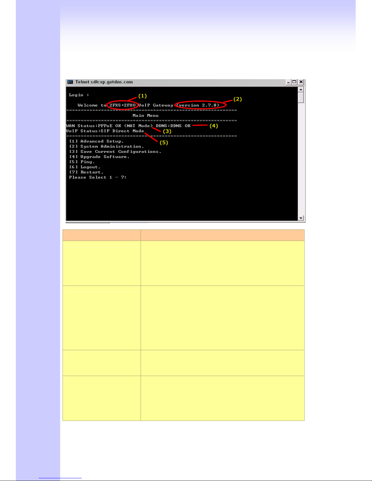
6. Input “Enter” and Show Welcome display.
7. Login, input the Password to login.(Password as the same as Access, default is admin)
8. Setting Gateway Configure like telnet mode
(Setting Table following as Telnet Setting table)
2.3.3 Telnet
Connect WAN/LAN port to Internet or PC and gateway at the same subnet. you can use telnet
remote to configure your gateway.
1. Connect Gateway online (Wan/Lan)
2. Remote Gateway by Telnet. If telnet successful, you will see Login display.
(For Example: telnet 222.222.222.1)
26
3. Input Password (Gateway Access password, Default: admin), If login successful, you will enter
the welcome display.
(1:Gateway Model 2:Firmware Version 3:Wan/Lan Status 4.DDNS Status 5:VoIP Status)
4. Gateway Telnet Setting Table, Use 1~9 a~z select setting, “ESC” is back setting.
Item Setting Option
Main
[1] Advanced Setup.
[2] System Administration.
[3] Save Current Configurations.
[4] Upgrade Software.
[5] Ping.
[6] Logout.
[7] Restart.
[1]Advanced Setup 1.WAN Setting
2.LAN Setting
3.Virtual Server
4.Dynamic DNS
5.Network Management
6.VoIP Basic
7.Dialing Plan
8.VoIP Advance Setting
9.Hot Line Setting
a.Port Status
[1]Advanced Setup
……1.WAN Setting
1.Change WAN Type to DHCP
2.Change WAN Type to Fixed IP
3.Change PPPoE Username
4.Change PPPoE Password
[1]Advanced Setup
……2.LAN Setting
1.Change to Bridge Mode
2.Change LAN IP Address
3.Disable DHCP Server
4.Change Start IP Address
5.Change End IP Address
6.Change DNS Server IP
7.Change Lease Time

27
[1]Advanced Setup
……3.Virtual Server
1.Add Virtual Server
2.Delete Virtual Server
[1]Advanced Setup
……4.Dynamic DNS
1.Change DDNS username
2.Change DDNS password
3.Change DDNS domain name
4.Change DNS server IP
[1]Advanced Setup
……5.Network Management
1.Change web server port
2.Change telnet server port
[1]Advanced Setup
……6.VoIP Basic
1.Change VoIP Protocol to H.323
2.Change Port Number/Account/Password
3.Enable/Disable Public account
4.SIP hunting setting
5.Change SIP Proxy Server IP Address/DNS
6.Use net2phone
7.Change Register Interval(seconds)
8.Enable/Disable SIP authentication
9.NAT Pass Method
a.STUN Server address
b.SIP realm
c.Outbound Proxy Server address
d.Change SIP Local Port
[1]Advanced Setup
……7.Dialing Plan
1.Add Outbound Direct Call
2.Delete Outbound Direct Call
3.Add Inbound Direct Call
4.Delete Inbound Direct Call
[1]Advanced Setup
……8.VoIP Advance Setting
(1)Sip Advance
1.Set DTMF Relay Mode
2.Change FAX Mode
3.Change RFC2833 Payload(96-127)
(2)Telephone Advance
1.VAD(Silence Compression)On/Off
2.Change Codec
3.Enable/Disable UK PSTN Tone Detection?
4.Enable/Disable Dial Complete Tone
5.Dial Termination Key Setting
6.FXS Parameters Setting
1.Change FXS Impedance
2.Change Phone In Volume
3.Change Phone Out Volume
4.Flash Detection
5.Ring Frequency
6.FXS Battery reversal generation
7.FXO Parameters Setting
1.Change FXO Impedance
2.Change Line In Volume
3.Change Line Out Volume
4.Change FXO Tx Gain
5.Change FXO Rx Gain
6.Flash Duration
7 DTMF Tone Power
8.FXO Transmit Hybrid
9. Answer Supervision Setting
a. Change Ringer Voltage Threshold
b. Enable Line Silence Disconnect
c. Change FXO Answer delay time
d. FXO Ringer Voltage Filter Setting

28
(3)Network Advance
1.Disable Smart QOS
2.Bandwidth Control
3.G.723 Bandwidth
4.G.729 Bandwidth
5.Set IP TOS
[1]Advanced Setup
……9.Hot Line Setting
1.Change Port1 Hot Line Number
2.Change Port2 Hot Line Number…….(To your own port)
[2] System Administration.
1.Save Configuration
2.Access Control
3.Set to Default
4.System Information
5.NTP Setting
6.Syslog Setting
2.3.4 Web User Interface
The gateway has a built-in HTTP(Web) server for configuration. Before you use the gateway to
access the Internet, you should set up a management PC to log into the router for further
configuration. The management PC may be configured with a fixed or dynamically assigned IP
address. For a fixed IP address, use an IP address from a 192.168.1.0/24 network, such as
192.168.1.10.
For a dynamic IP address, you need to set the PC as a DHCP client, and then restart or renew
the network settings. The DHCP server of router is enabled by default so the PC will then be
assigned an IP address and related settings by the router. The following examples are for a
MicrosoftTM Windows 2000/XP machine set to use a dynamic IP address.
Checking the Network IP Configuration
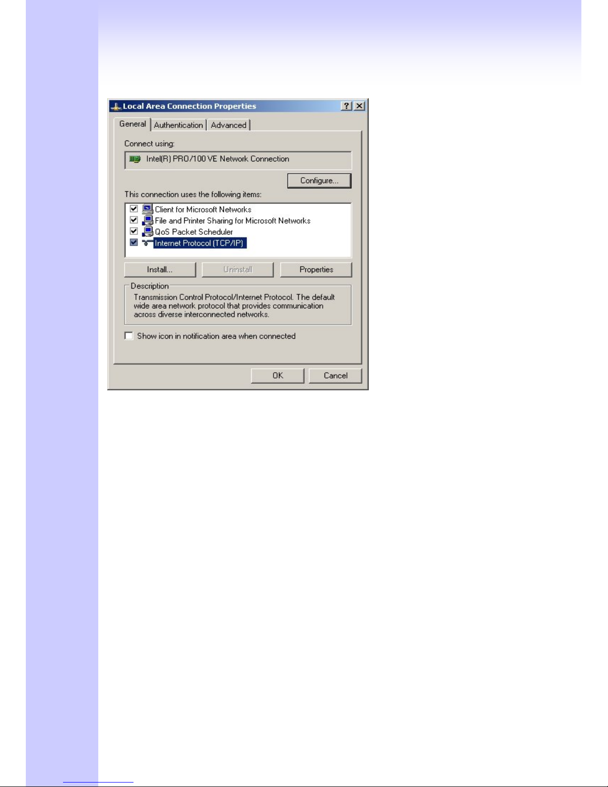
The following explains how to setup the Transmission Control Protocol/Internet Protocol
(TCP/IP) in Windows 2000/XP. For more detailed information on TCP/IP setup, refer to the
Windows 2000/XP help files. For other operating systems refer to the user manuals.
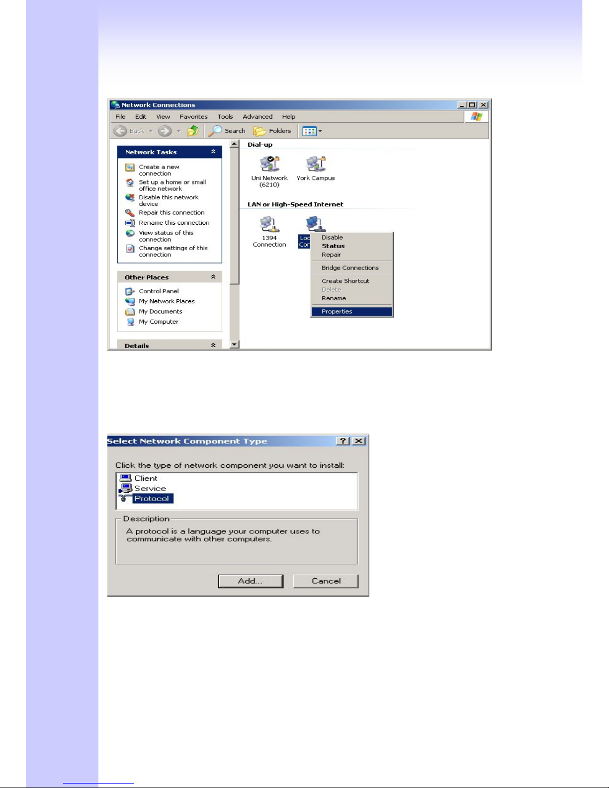
1. On the desktop, Please enter start -> control panel -> network setting.” Click Properties. The
Network screen will open.
29
(Your particular system will be different from the screen shown here.)
Check that you have an Ethernet network card installed. If not, refer to the card manufacturer’s
documentation and install the card and drivers.
If your card is installed,
1. Click the Add button. The Select Network Component Type dialog box will open. The box will
show four options: Client, Adapter, Protocol, and Service.
2. Select Protocol and click the Add button. The Select Network Protocol dialog box will open.
3. Select Microsoft in the left scrolling window then selects TCP/IP in the right, and click OK.”.
You will be returned to the Network dialog box.
30
Configuring the TCP/IP Protocol
1. On the Network dialog box Configuration card, select TCP/IP and then click Properties.” The
TCP/IP Properties dialog box will open.
2. On the IP Address tab, click Obtain an IP address automatically. As the DHCP (Dynamic Host
Configuration Protocol) server built into the router is enabled by default, your computer will get an
IP address, subnet mask, and other related IP network settings from the router.
3. On the DNS Configuration tab, click Disable DNS”.
4. Click the Gateway tab.
5. Make the New gateway and Installed gateways fields blank and click OK. A dialog box will pop
up asking you to restart the PC. Click Yes”.
Checking TCP/IP settings
1. After completing the previous steps, click Start -> Run -> and type ipconfig /all. The IP
Configuration window will open. If the PC does not show an IP address in the 222.222.222.51 to
222.222.222.100 range, click the ipconfig /release button to release the current configuration.
Wait a few seconds and click “ipconfig/renew” to get a new IP configuration from the router.
2. If the IP configuration is correct, you will be able to use the PING diagnostic utility built into
Microsoft Windows to ping the router. Click Start -> Programs -> MS-DOS Prompt. A command
mode window will open.Type “ping 222.222.222.1” (default IP of the router) to check the network
connectivity. If both hardware and software are correct, your computer will receive a response
from the router as shown on the next page. If not, verify that the Ethernet cable is connected to
the router properly and the Ethernet port LED on the front panel is lit.
 Loading...