

SoundTube WLL-TR-1p, WLL-RX1p, WLL-TX1 Install Instructions Manual
WLL-TR-1p
Install Instructions For:
WLL-TR-1p (WLL-TX1 transmitter and WLL-RX1p receiver/amp).
© 2012 SoundTube Entertainment, Inc. All rights reserved. PN INS-WLL-TR-1p Rev01.27.12
1.435.647.9555
|
800.647.TUBE
|
www.soundtube.com
Warning
SoundTube products must be installed by a professional audio installer/contractor. For safety and for
optimum audio performance, installer must follow all directions issued by SoundTube Entertainment.
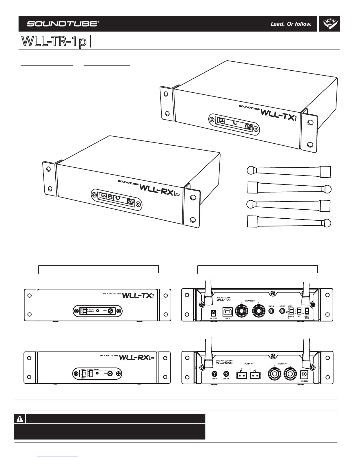
Front Rear
Transmitter Box Contents
1- WLL-TX1 wireless transmitter
1- 5v power supply
2- Half rack mount adapters
2- Antenna
TX unit- Transmitter
TX unit- Transmitter
RX unit- Receiver/Amp RX unit- Receiver/Amp
TX unit- Transmitter
RX unit- Receiver/Amp
Antenna (4)
Receiver Box Contents
1- WLL-RX1p wireless receiver/amp unit
1- 32v power supply
2- Half rack mount adapters
2- Antenna
2- Two-pin Euro-block connectors
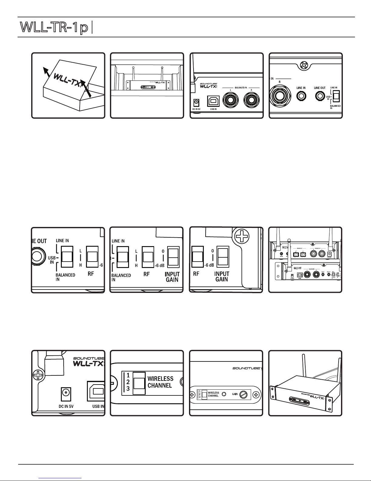
1. Remove unit from box.
8. For best results, Transmitter
and Receiver antennas should
face the same direction (either
vertically or horizontally).
7. Set INPUT sensitivity switch
at 0 dB for normal use. If using
a high output source, set the
switch to -6dB.
6. Set RF power switch. Two
options are available, High (H)
and Low (L). The High setting is
recommended for maximum
distance. The low setting is for
installations where 2 or more
TX-1’s are on the same channel
within 60-70 ft of each other.
5. Set input switch to match the
desired input source.
2. Determine location for
placement of WLL-TX1. The
WLL-TX1 may be installed in an
equipment rack (half rack
adapter required) or on a shelf.
4. If desired, the variable LINE
OUT mini jack can be
connected to an external
device such as an ADA hearing
assistance system.
3. Connect desired input source
to rear panel. You may use
balanced (1/4” TRS) connectors,
unbalanced mini or USB.
Multiple sources may be
connected but only the source
selected on the input switch
(step 5) will be sent to the
transmitter. When connecting
through the USB input do not
connect an input to the
balanced or line in.
11. After installation of
WLL-RX1(p) unit(s), apply power
to WLL-TX1. Adjust front panel
gain knob as needed. The gain
control will adjust the level of
both the input audio and the
LINE OUT feed.
10. On front panel, select transmit
channel 1, 2 or 3. NOTE: the
WLL-RX1(p) unit(s) must be set on
the same channel.
9. Connect power supply to DC
IN 5V connector.
12. Done!
(The LED on the front panel
will be red when power is
applied to the TX unit. It will
turn blue when the TX unit is in
communication with the RX).
WLL-TR-1p
Install Instructions For:
WLL-TR-1p (WLL-TX1 transmitter and WLL-RX1p receiver/amp).
WLL-TX1 Install Instructions
Installation Notes: 2a: an installation that puts the WLL-TX1 in line-of-sight with the WLL-RX1(p) will provide the best results. 2b: Do not install transmitter
more than 230 feet (70 meters line of site or 50 meters indoors) from the desired receiver location(s). 3a: If using the USB input, the WLL-TX1 will appear as
an audio device on your computer’s control panel.
 Loading...