

SoundTube SM590i, SM500i Install Instructions Manual
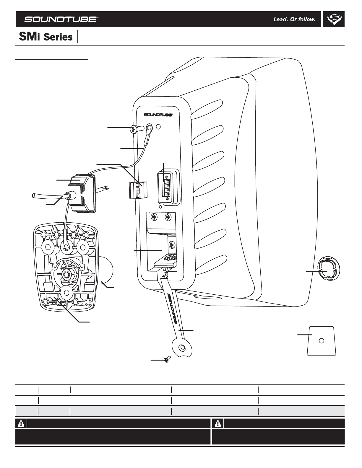
Box contents
1 Speaker
1 Terminal weather boot
1 Mounting bracket with ball joint
1 Safety cable
2 Safety cable anchor screws
1 Euroblock connector
1 Grille-mounted tap switch cover
1 Theft-resistant screw
1 Extra - Ball joint anchor pad
Safety cable anchor screw
Install Instructions For:
SM590i and SM500i speaker
Safety cable
1.435.647.9555
|
800.647.TUBE
|
www.soundtube.com
Terminal
weather boot
Signal wire
Euroblock connector
Clamping cavity
Ball joint
Mounting bracket
Euroblock jack
Speed Lever™
Grille-mounted
tap switch cover
Ball joint anchor pad
Theft-resistant screw
Transformer Taps Settings
Voice Coil
SM500i
SM590i
70.7 Volt Transformer Taps (dB) 100 Volt Transformer Taps (dB) 25 Volt Transformer Taps (dB)
33W=103.5, 17W=101, 9W=98, 6W=96.5, 3W=93.5 33W=103.5, 17W=101, 9W=98, 6W=96.5 5W=95.5, 2.5W=92.5, 1.3W=89.5, .63W=86.58 Ohm=108 dB
33W=105.5, 17W=103, 9W=100, 6W=98.5, 3W=95.5 33W=105.5, 17W=103, 9W=100, 6W=98.5 5W=97.5, 2.5W=94.5, 1.3W=91.5, .63W=88.5 8 Ohm=110 dB
Warning Warning
SoundTube speakers must be installed by a professional audio installer/contractor. For safety and for
optimum audio performance, installer must follow all directions issued by SoundTube Entertainment.
© 2005 SoundTube Entertainment, Inc. All rights reserved. PN INS-SMI Rev 07.15.05
Do not spec or install speaker near support beam, ventilation duct or
other structure that may interfere with speaker function or dispersion.
Install Instructions For:
SM590i and SM500i speaker
1.435.647.9555
|
800.647.TUBE
|
www.soundtube.com
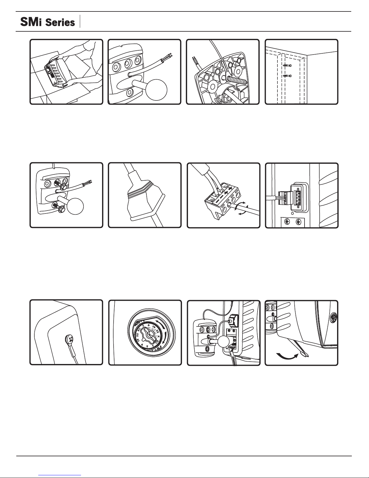
1. Unpack speaker and
SpeedLever™ mounting
hardware.
5. Securely fasten mounting
bracket to surface (user
must supply fasteners).
Mounting bracket may also
be strap-mounted to pole or
appropriate anchor point.
Max strap width: 19.05 mm
(.75 in)
2. Thread signal wire
through hole in center of
bracket.
6. Slip terminal weather
boot over signal wire. For
environmental applications,
put RTV silicone around
nipple and base when
installation is complete.
3. Attach safety cable,
thread mounting screw (not
supplied) through eyelet in
supplied safety cable on
rear face of bracket.
7. Connect signal wire to
4-pin Euroblock plug. Tighten
unused terminal screws. Use
inside positive and negative
inputs for either voice coil or
distributed systems. For
daisy chaining, use outside
positive and negative
terminals.
4. Choose a secure
mounting surface with
sufficient strength to reliably
hold the speaker. Mounting
bracket accommodates
screwing, through-bolting &
strapping applications.
8. Insert 4-pin Euroblock
plug into Euroblock jack on
rear of speaker. Connectors
are keyed for polarity.
9. Use supplied screw to
connect the safety cable to
the insert on the rear panel
of the speaker.
10.Select the tap position by
removing the rubber plug on
grille to access rotary switch
Switch is preset to maximum
tap setting in 70.7 V mode
(33 W or 66 W). Select desired
setting and reinsert rubber
plug. Note: The grille-mounted
tap switch cover is keyed; be
sure flat edge of plug lines up
with flat edge of hole in grille.
11. Mount the speaker to
the bracket by positioning
ball joint in the center of the
clamping cavity. Push the
speaker onto the ball,
ensuring proper positioning.
When repositioning the
speaker, it may be necessary
to use supplied ball joint
anchor pad for maximum
support.
12. Aim the speaker and
lock the lever, then use the
theft-resistant screw to
secure the lever in position.
Open SpeedLever to
reposition speaker.
DO NOT TWIST Speaker
after lever is locked.
 Loading...