

Soundtube SM400i User Manual
Box contents
1 Speaker
1 Terminal weather boot
1 Theft resistant u-bracket
1 Safety cable
1 Safety cable anchor screw
1 Euroblock connector
1 Grille-mounted tap switch cover
1 Allen wrench
2 Port plugs
Safety cable
Install Instructions For:
SM400i - UL listed 1480
1.435.647.9555
|
800.647.TUBE
|
www.soundtube.com
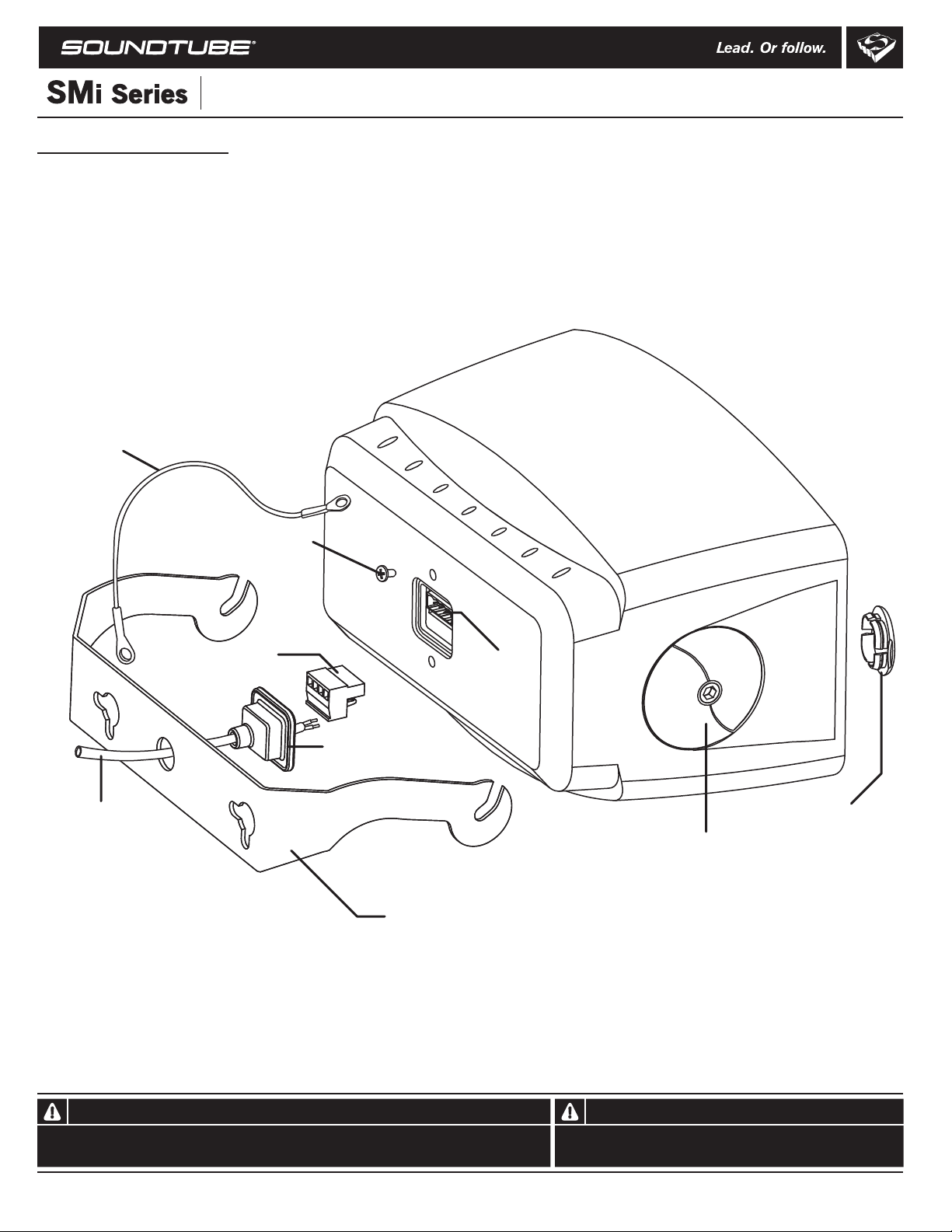
Signal wire
Safety cable anchor screw
Euroblock connector
Euroblock jack
Terminal
weather boot
Grille-mounted
tap switch cover
U-bracket clamping knob
U- bracket
© 2008 SoundTube Entertainment, Inc. All rights reserved. PN INS-SM 400i Rev 05.28.08
Warning Warning
SoundTube speakers must be installed by a professional audio installer/contractor. For safety and for
optimum audio performance, installer must follow all directions issued by SoundTube Entertainment.
Do not spec or install speaker near support beam, ventilation duct or
other structure that may interfere with speaker function or dispersion.
Install Instructions For:
SM400i - UL listed 1480
1.435.647.9555
|
800.647.TUBE
|
www.soundtube.com
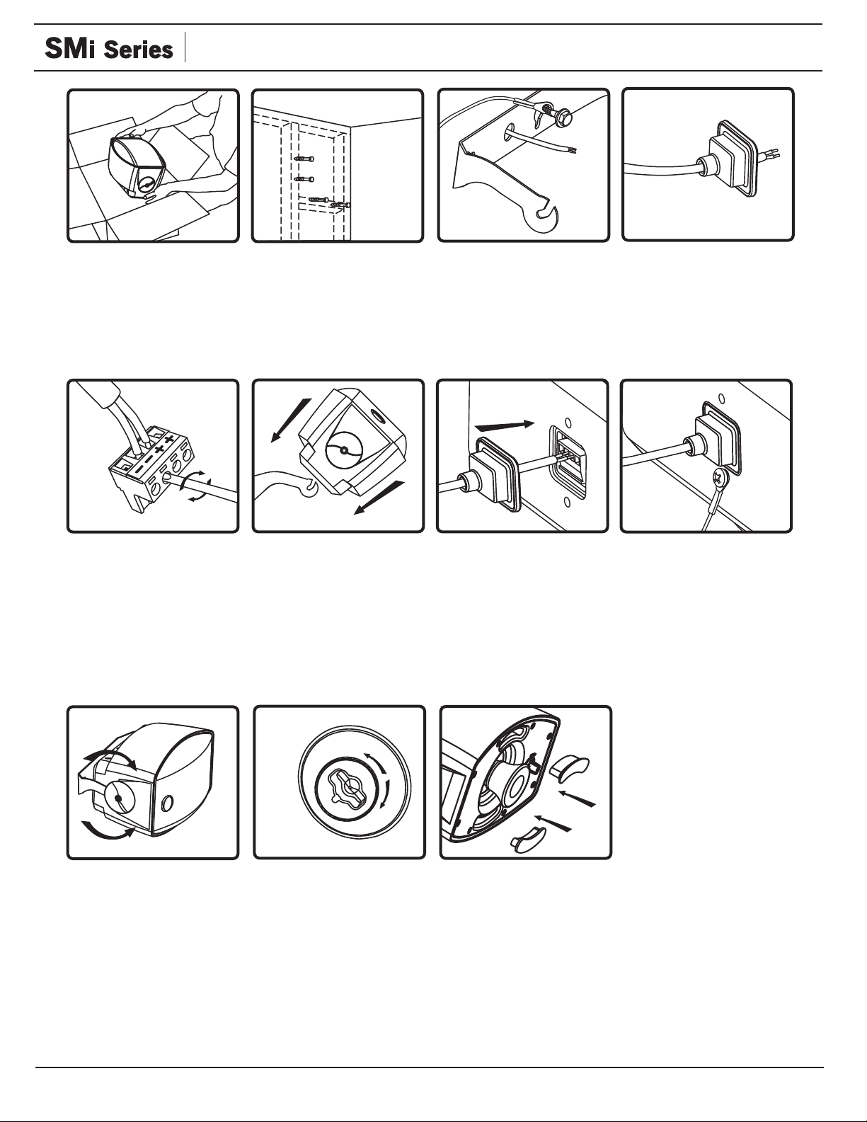
1. Unpack speaker and
mounting hardware.
5. Connect signal wire to
4-pin Euroblock plug. Tighten
unused terminal screws. Use
inside positive and negative
inputs for either voice coil
or distributed systems. For
daisy chaining, use outside
positive and negative terminals.
2. Choose a secure mounting
surface with sufficient
strength to reliably hold
the speaker.
6. Use provided allen wrench
to loosen knobs on sides of
speaker. Tilt speaker 45º
(grille up) and slide on to
bracket.
3. Mount u-bracket with
clamping slots pointing
upward. Securely fasten
mounting bracket and
safety cable to surface
(user must supply fasteners).
8. Insert 4-pin Euroblock
plug into Euroblock jack on
rear of speaker. Connectors
are keyed for polarity. Insert
terminal weather boot.
Port protection for SM400i
4. Slip terminal weather
boot over signal wire. For
environmental applications,
put RTV silicone around
nipple and base when
installation is complete.
9. Connect safety cable to
rear of speaker.
10. Aim speaker and
tighten knobs.
11. Select the tap position by
removing the rubber plug on
grille to access rotary switch.
The switch is preset to the
maximum tap setting in
70.7 V mode (20W). Select
desired setting and reinsert
rubber plug. Done!
To enhance protection of internal
components from humidity and
other potentially corrosive
elements, use provided port
plugs to seal enclosure. Use
RTV silicone around edge of the
port plug for increased protection.
 Loading...