

SoundTube Motion Sensor FP Series, FP Series Install Instructions Manual
FP Series
FP Series
Install Instructions For:
Motion Sensor
1.435.647.9555
|
800.647.TUBE
|
www.soundtube.com
ATTENTION
The FP pod comes with the motion sensor lens preset to a wide angle and will trigger audio
activation from movement beyond the diameter of the dome. For applications with a narrow motion
sensor angle, follow these instructions. The narrow motion sensor lens will trigger audio activation
only when someone is standing directly underneath the dome.
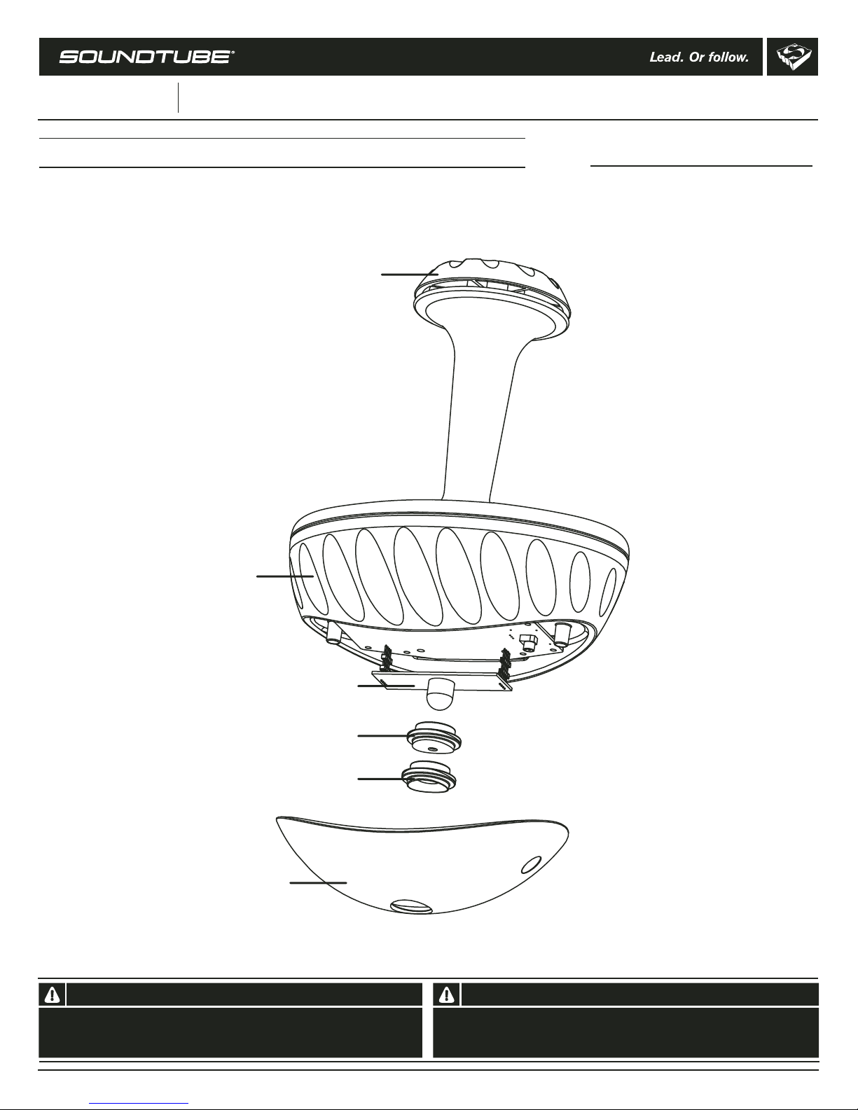
Dome Clamp
Motion Sensor Accessory Contents
1 FP Pod with wide lens
1 Narrow lens
FP Speaker Pod
Motion Sensor
Pod Cover
Motion Sensor
Motion Sensor
lens (narrow)
Motion Sensor
lens (wide)
(Optional, included)
(Standard)
© 2005 SoundTube Entertainment, Inc. All rights reserved. PN INS-FP6-MS REV 01.12.06
Warning Warning
SoundTube speakers must be installed by a professional audio
installer/contractor. For safety and for optimum audio performance,
installer must follow all directions issued by SoundTube Entertainment.
Do not spec or install speaker near support beam, ventilation
duct or other structure that may interfere with speaker function
or dispersion.
FP Series
FP Series
Install Instructions For:
Motion Sensor
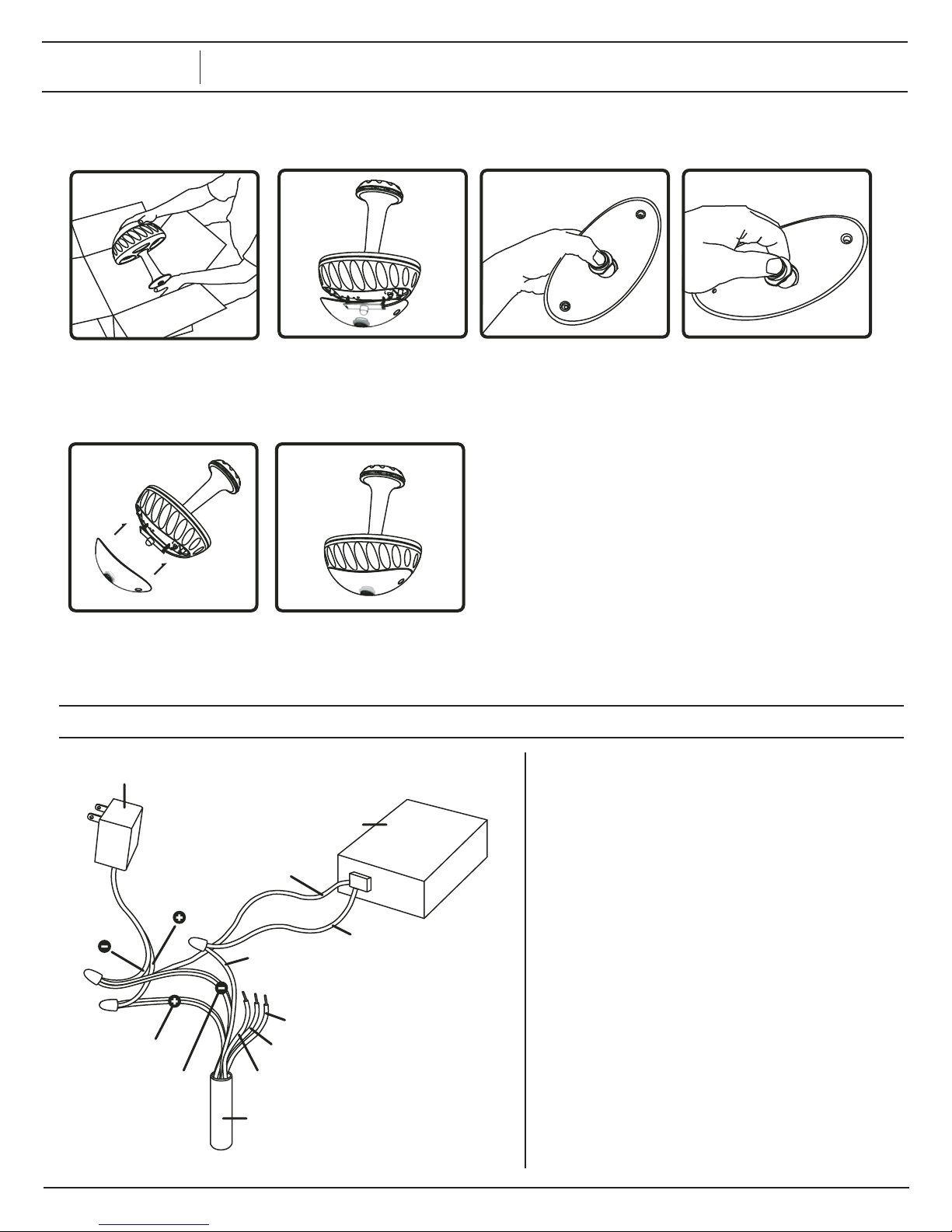
To adjust the sensor from wide angle to narrow angle:
1.435.647.9555
|
800.647.TUBE
|
www.soundtube.com
1. Unpack FP speaker pod
and FP Dome.
5. Place pod cover back on
2. Remove motion sensor
pod cover.
6. Complete.
FP unit.
Wiring Diagram for Motion Sensor
Power Source
(not included)
Voltage Sensor Controller
(not included)
Ground
Positive
Ground
White/ Green Signal wire
Orange White /
Orange
Brown White /
Brown
for 5 Volt ttl signal
Blue White (unused)
Blue Signal wire for
1k to 12 Volt pullup
Green (unused)
Cat V Wire From Pod
Signal wire
3. Remove motion sensor lens. 4. Place narrow lens into pod
cover. Make sure lens is flush
with outside of pod cover.
Align the flat side of the lens w/
the flat side of the pod cover.
Power supply and voltage sensor control
not included.
1. Attach the +12 V from the power supply to the
Orange white and orange wire pair.
2. Attach the ground from the power supply to the brown
white and brown wire pair.
3. Attach the ground from the voltage sensor controller to
the brown and white wire pair also.
4. Attach the signal wire to the white/green single wire.
5 Volt ttl signal (White/ Green Signal wire)
• 0 Volts = motion detected
• 5 Volts = no motion detected
• The green and blue/white
wires are unused.
1k to 12 Volt pullup (Blue Signal wire)
• 12 Volts = motion detected
• 0 Volts = no motion detected
• The green and blue/white
wires are unused.
 Loading...