

Page 1
TM
gy
s
s
New Dimensions in Digital Sound Technolo
USA Trains PA-1
Sierra Sound System Installation Notes
Overview
This application note describes how to install your Sierra
sound system in the USA Trains PA-1. Please read through
the entire document to become comfortable with the
steps involved before beginning the installation. No major
mechanical modifications are required and the entire
process can be completed in a few hours.
Tools You Will Need
■ #2 Phillips Screw Driver with 4” shank
■ Wire cutters
■ Wire strippers
■ 25W Solder Iron
■ Rosin core solder
■ 1/4” Drill Bit
■ Electric Hand Drill or equivalent
■ Superlock Fastener Radio Shack #64-2360
■ 2 Sided Foam Tape Radio Shack #64-2343
■ Heat Shrink Tubing SoundTraxx P.N. 810037
INSTALLATION GUIDE
Installation
1. Locomotive Disassembly
Use a foam pad or thick towel to support the
locomotive body and turn it upside down. Be
careful of the horns and other details atop the
locomotive.
2. Remove the two screws securing the fuel tank
to the locomotive frame. Remove the fuel tank
and side ‘skirts’ (Figure 1).
3. Remove the four screws securing the pilot to
the locomotive frame as shown in Figure 2.
Remove the pilot to expose two screws
underneath.
4. Pop the lower ends of the handrails from the
step ladders on each side of the locomotive.
See Figure 3. You may also wish to remove the
step ladders from the locomotive frame to
prevent them from accidentally breaking off
while completing this installation.
Figure 1
Remove (4) Screw
Figure 2
Remove Hand-rails from step ladder
Figure 3
Page 2
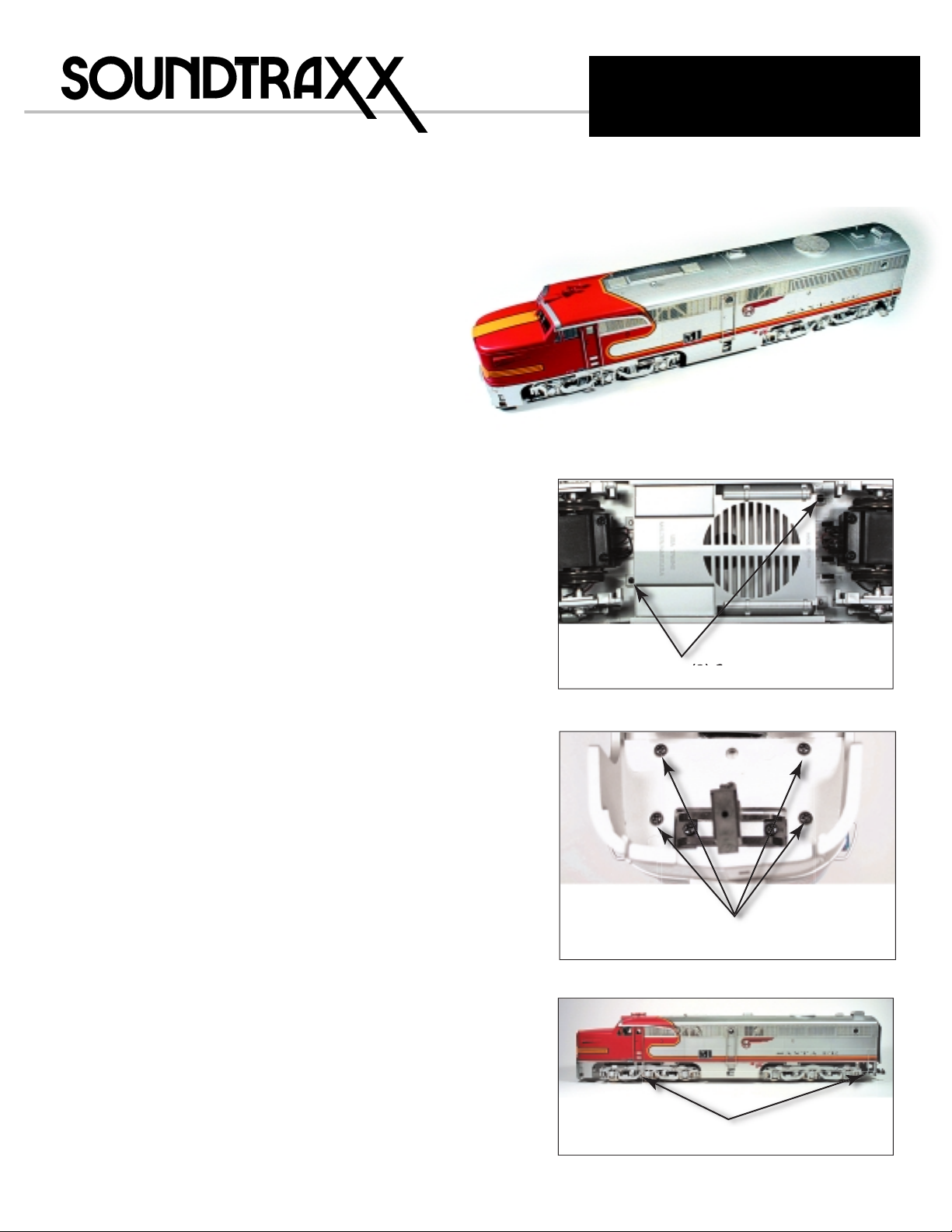
5. Remove the ten screws securing the
n
locomotive frame to the body shell as shown in
Figure 4. The screws near the truck side frames
will be most easily removed using a #2 Philips
screw-driver with a long shank. Carefully
separate the body shell from the frame.
Top View of Locomotive Floor
(rear)
1/4"
Drill 1/4" hole
for Charging Jack
(optional)
Mounting
Post
Remove (10) Screws at Locations show
Figure 4
6. There is an unused plug on the USA PC board at
the center of the locomotive labeled “SPEAK1”.
Cut a 9” length from the supplied red wire. Strip
and tin the ends. Solder one end directly to the
left plug post. Cut a 14” length from the
supplied green wire. Strip and tin the ends.
Solder one end to the right plug post. Insulate
the connections with heat shrink tubing (See
Figure 5).
2-1/8"
Figure 6
1/2"
Mounting
Post
5/8"
Control Switch (optional)
Drill 1/4" hole
for Remote Volume
Drill 1/4" hole for
Power Switch
1/2"
5/8"
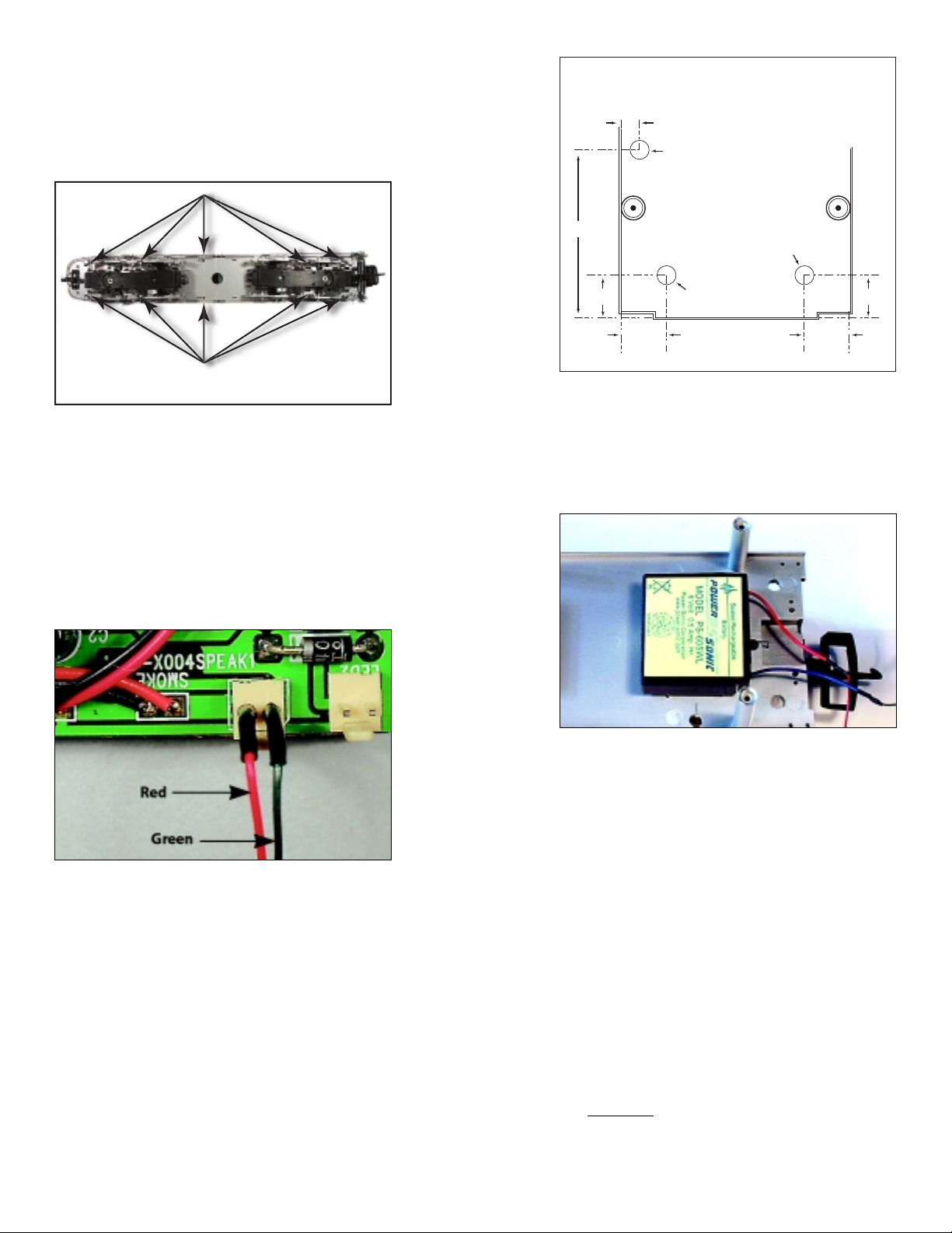
10. Cut two 1”x1-1/2” strips of double-sided foam
tape and place them on one side of the battery.
Snugly press the battery against the floor close
to the coupler spring wire screw as shown in
Figure 7.
Figure 5
7. Locating the Switches
Mark and drill a 1/4” hole for the power switch
in the rear of the locomotive floor using Figure
6 as a guide.
8. If you are installing the optional Battery
Charging Kit (PN 810076), mark and drill a 1/4”
hole for the charging jack as shown in Figure 6.
9. If you are installing the optional Remote
Volume Control Switch (P.N. 810073), mark and
drill a 1/4" hole for the charging jack as shown
in Figure 6.
Figure 7
11. Installing both the Power Switch and
Battery Charging Jack
(Skip to Step 12 if you are not installing the
Battery Charging Kit.)
The following steps describe the installation of
both the Power Switch and the optional
Charging Jack. Insulate the soldered
connections with shrink tubing to prevent
accidental shorts.
n Cut the battery wire harness in half and strip
3/16” of the insulation from the ends of each
wire. Twist the ends of the (-) negative black
wire together and solder them to the Charging
Jack’s A terminal. Insulate the connection with
heat shrink tubing.
CAUTION: It is very easy to get the terminals A,
B, and C of the charging jack confused. Refer to
the drawing and make sure the correct
terminals are used.
Page 3

BLACK
d
ed
C
e
SA
'
t
al
e
s
g
a
ot Used
d
2
356
d
d
of
)
e
SA
'
t
al
s
g
a
ot Used
d
356
RED
- +
6V Battery
Battery
Charging Jack
Green Wir
from U
'SPEAK1
ermin
To Sierr
Terminal 7
Not Use
Figure 8
B
To Right
Track Pickup
To Terminal 7 on
Sierra board
A
BLACK
RED
C
To r
wire of
Charging Jack
Terminal
To red wir
f Sierra'
battery plu
N
Sierra Battery
Connector Plug
Power
Switch
Not use
n Solder the positive (+) red wire from the battery
to the Charging Jack’s B terminal and insulate
the connection with heat shrink tubing.
n Cut a 5” length from the remaining supplied red
wire. Strip and tin the ends. Solder one end to
terminal C of the Charging Jack. Solder the
other end to terminal #4 of the Power Switch.
Insulate both connections.
n Solder the positive (+) red wire from Sierra’s
Battery Connector Plug to terminal #5 of the
Power Switch and insulate the connection.
n Cut a 9” length from the remaining supplied
green wire. Strip and tin the ends. Solder one
end to terminal #2 of the Power Switch and
insulate the connection.
n Solder the free end of the green wire from the
‘Speak1’ plug (Step 6) to terminal #1 of the
Power Switch and insulate the connection.
n Install the charging jack in the hole you drilled
in Step 8. The threaded shank of the battery
charging jack may not be long enough to go
through the thick plastic of the frame and have
room for the nut. We suggest using epoxy to
glue the jack in place. Be careful to not get any
glue inside the jack’s opening or barrel.
n Install the Power Switch in the hole you drilled
in Step 7.
n After completing Step 11, skip to Step 13.
12. Installing Only the Power Switch
Since you are not installing the Battery
Charging Jack, wire the power switch as in
Figure 9. Insulate the soldered connections
with heat shrink tubing to prevent accidental
shorts.
n Cut the positive (+) red battery wire in half and
strip 3/16” of the insulation from the ends of
each wire.
n Connect the wire from the (+) battery terminal
to terminal #4 of the Power Switch and insulate
the connection..
n Connect the remaining wire to terminal #5 of
the Power Switch and insulate the connection.
n Cut a 9” length from the remaining supplied
green wire. Strip and tin the ends. Solder one
end to terminal #2 of the Power Switch and
insulate the connection.
n Solder the free end of the green wire from the
‘Speak1’ plug (Step 6) to terminal #1 of the
Power Switch and insulate the connection.
n Install the Power Switch in the hole you drilled
in Step 7.
RED
- +
To Right
To Terminal 7 on
Green Wir
from U
'SPEAK1
ermin
To Sierr
Terminal 7
Not Use
Track Pickup
Sierra board
6V Battery
Figure 9
13. Installing the Remaining Switches
If you have purchased a Remote Volume
Control Switch (P.N. 810073), install this switch
in the hole you drilled in Step 9.
14. If you plan to install an optional Coupler Clank
Sensor Switch (P.N. 810072) install it now using
the directions that come with the switch.
15. Trigger switches can be used to activate some
of Sierra’s sound effects by way of magnets
embedded in the roadbed. If you wish to use
this method of activating your sound effects
you will need to purchase P.N. 810074. Included
is one trigger switch and one magnet. One
trigger switch is required per effect and one
magnet per location. If you plan to use trigger
reed switches, install them according to the
instructions that came with them.
16. Cut a piece of double-sided foam tape (or
Superlock fastener) approximately 2” long. Peel
the backing off and place on the Sierra board
on top of the large chips on the side opposite
the terminal blocks. Peel the remaining
backing off of the tape and place on the floor of
the locomotive in front of the battery as shown
in Figure 10. Be sure to allow enough clearance
for the body shell.
BLACK
To re
wire
Battery (+
To red wire
f Sierra'
battery plu
N
Sierra Battery
Connector Plug
Power Switch
Not use
Page 4

- +
terminal 1, the black wire to terminal 2 and the
green wire to terminal 3.
21. Connect any other accessories you’ve installed,
including trigger reed switches, lights and
coupler clank sensor switches, following the
directions provided with the accessory.
22. Plug the battery harness plug into the socket at
the middle of the Sierra circuit board.
Figure 10
17. Installing the Speaker
Place the speaker in the fuel tank as shown in
Figure 11. Ensure that the speaker is flat on the
grill. Use the screws and clamps provided to
secure the speaker to the tank interior. Feed the
speaker wires through the large hole in the
floor of the locomotive above the fuel tank.
Figure 11
18. Make connections to the Sierra circuit board.
Use Figure 12 to guide you in making your
connections.
n Connect the speaker leads to terminals 9 and
10 on the Sierra circuit board.
19. Connect the green power lead from terminal #2
of the Power Switch (Figures 8 and 9) to
terminal 7 on the Sierra board. Connect the red
wire from the USA circuit board ‘SPEAK1’ plug
(Step 6) to terminal 8 of the Sierra board.
Caution: Use your finger to hold the socket firmly
against the circuit board when plugging in the
connector to prevent the socket from ripping off the
circuit board. The connector only goes in one way. It
is a snug fit and once plugged in, it is difficult to
remove. If you need to unplug the battery later, use
your thumb and forefinger to hold the socket firmly
against the circuit board, while using your other
hand to grasp the connector (NOT THE WIRES) and
gently wiggle it from side to side as you pull the
connector straight out. Excessive force may pull out
the wires or rip the mating connector off of the
circuit board.
23. Attach the body shell to the frame, ensuring
that all wires are inside the frame’s edge and
replace the screws. Re-install the pilot.
Re-install the hand-rails and the step ladders
you removed in Step 4.
24. Make sure the speaker wires are tucked inside
the fuel tank and there is nothing “pinched.”
Replace the fuel tank with the securing screws.
25. Place the locomotive on a section of track. Turn
the power switch ‘on’. The Sound switch on the
underside of the locomotive must also be set to
ON. You should hear the engine start up. Slowly
apply power. You should hear two short horn
toots as the locomotive moves forward and
three horn toots as the locomotive moves
backward. Make certain that there are no short
circuits detected. If horn signals are reversed,
switch the wires to Sierra’s terminals 7 and 8. As
you increase the throttle, you will hear the
engine RPMs increase and the bell will come on.
Refer to your owner’s manual for programming.
20. If you have installed the Remote Volume
Control Switch, connect the yellow wire to
Figure 12
Speaker +
Speaker -
Bell Trigger Switch
Airhorn Trigger Switch
Dynamic Brake Trigger Switch
CouplerTrigger Switch
Track Pickup - USA circuit
board ‘SPEAK1’ right terminal
GREEN
Power On/Off
Switch
9
10
11
12
13
14
15
16
Not used
Optional
Recharging Jack
BLACK
6V Battery
8
7
6
5
4
3
2
1
- +
Enjoy your SoundTraxx equipped PA-1!
GREEN
To Terminal 7
Light 2Light 1
Remote
Volume
Control
RED
Track Pickup USA circuit
board ‘SPEAK1’
left terminal
030052 Rev. B 121703
 Loading...