

Page 1

TM
gy
New Dimensions in Digital Sound Technolo
USA Trains GP30
Sierra Sound System Installation Notes
Overview
This application note describes how to install your Sierra sound
system in the USA Trains GP30. Please read through the entire
document to become comfortable with the steps involved
before beginning the installation. No major mechanical
modifications are required and the entire process can be
completed in a few hours.
Tools You Will Need
■ #2 Phillips Screw Driver
■ Wire cutters
■ Wire strippers
■ 25W Solder Iron
■ Rosin core solder
■ 1/4” Drill Bit
■ Electric Hand Drill or equivalent
■ Superlock Fastener Radio Shack #64-2360
■ 2 Sided Foam Tape Radio Shack #64-2343
INSTALLATION GUIDE
Installation
1. Locomotive Disassembly
Use a foam pad or thick towel to support the long hood portion of
the diesel and turn it upside down. Be careful of the horns,
whistles, or other details that may be on top of the locomotive.
2. Remove the four screws that hold the fuel tank (Figure 1) to the
bottom of the frame. Remove the fuel tank.
3. Remove fourteen screws that hold the cab and body shell to the
frame. There are screws under the trucks. Remove the side frames
to move the wheel assemblies out of the way and access the
remaining screws (Figure 2). Remove the screws that hold the cab
to the frame.
4. Remove the body shell and cab.
5. Cut two 0.30”x1.00” strips of double-sided foam tape. Place one
strip along the bottom and the other along one side of the battery.
Snugly press the battery against the floor and post as shown in
Figure 3. Be sure to allow clearance for the body shell.
6. There is an unused plug on the USA PC board labeled “SPEAK1”.
Solder a red wire directly to the right plug post and a green wire to
the left. The right and left posts connect to the locomotive’s right
and left track pickups respectively. Secure each with heat shrink
tubing (Figure 4).
Figure 1
Figure 2
Figure 3
Page 2
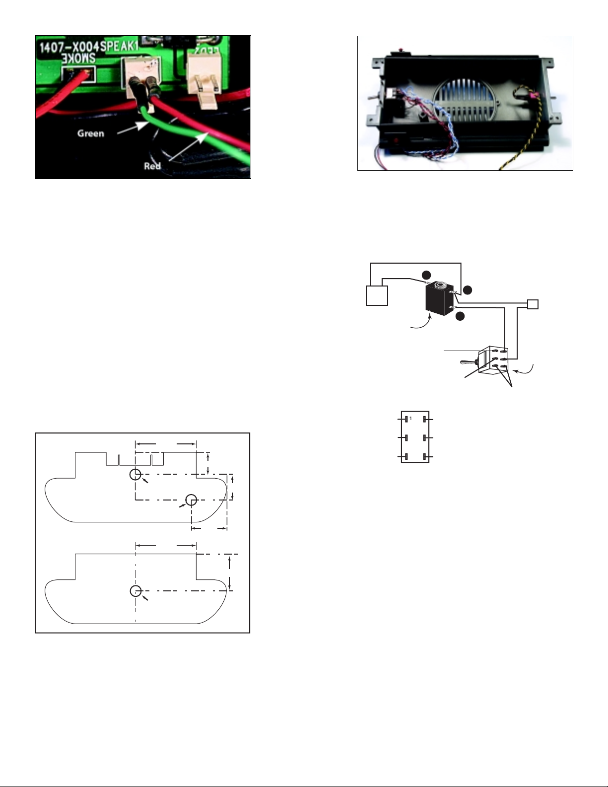
Figure 4
d
of
C
t
p
e
n
g
a
ot Used
sed
356
7. Installing the Switches
Mark and drill a 1/4” hole in the front end of
the fuel tank, approximately 1/3 from the top of
the tank, near the center. (Figure 5). It may be
easier to wire the switch before mounting it
(Steps 10 or 11). If your layout has very tight
radius turns you may have to find alternate
mounting locations for some of the switches.
8. If you have purchased the Battery Charging Kit
(P.N. 810076), mark and drill a 1/4” hole in the
front end of the fuel tank roughly 0.59” below
the Power Switch and 0.88” from the furthest
edge of the fuel tank . See Figure 5.
Figure 6
Wire the Charging Jack and power switch as
shown in Figure 7. Insulate the soldered
connections with shrink tubing or electrical
tape to prevent accidental shorts.
BLACK
B
RED
- +
6V Battery
Battery
Charging Jack
To Right
Track Pickup
A
BLACK
RED
C
Sierra Battery
Connector Plug
Power Switch
9. If you are installing the optional Remote
Volume Control Switch (P.N. 810073), mark and
drill a 1/4" hole in the rear end of the fuel tank,
near the center. See Figure 5.
1.39"
0.51"
Drill 1/4" hole
for Power Switch
Drill 1/4" hole for
Charging Jack
1.39"
Drill 1/4" hole
for Remote
Volume Control
Switch
0.88"
Figure 5
End View of
Fuel Tank
(front end)
End View of
Fuel Tank
(rear end)
10. Installing both the Power Switch and
Battery Charging Jack
(Skip to Step 11 if you are not installing the
Battery Charging Kit.)
Half of the power switch is used to disable the
battery power and the other half disconnects
one of the track pick ups.
0.59"
0.85"
To Terminal 7 on
To Righ
Track Picku
To Sierr
Terminal 7
Not U
Figure 7
Sierra board
To red wire
Charging Jack Terminal
To red wir
of Sierra's gree
battery plu
N
Not use
n Cut the battery wire harness in half and strip
the insulation from the ends of each wire. Twist
the battery negative (-) black wire and the
Sierra Battery Connector Plug negative (-) black
wire together. Insert into the hole in the
Charging Jack’s A Terminal and solder.
n Connect the positive (+) red wire from the
battery to the Charging Jack’s B terminal.
n Solder a 4” piece of red wire from the Charging
Jack’s terminal C to the power switch terminal
#4.
n Solder the Sierra Battery Connector Plug’s
positive (+) red wire to the power switch
terminal #5.
n Install the charging jack in the hole you drilled
in Step 8. The threaded shank of the battery
charging jack may not be long enough to go
through the thick plastic of the fuel tank and
have room for the nut. We suggest using epoxy
to glue the jack in place. Be careful to not get
any glue inside the jack’s opening or barrel.
Page 3

n If you have not already done so, install the
d
of
)
t
p
e
n
g
a
ot Used
d
356
Power Switch in the hole you drilled in Step 7.
n After completing Step 10, skip to Step 12.
CAUTION: It is very easy to get the terminals A,
B, and C of the charging jack confused. Refer to
the drawings and make sure they are right.
11. Installing Only the Power Switch
Half of the power switch is used to disable the
battery power and the other half disconnects
one of the track pick ups. Since you are not
installing the Battery Charging Jack, wire the
power switch as in Figure 8. Insulate the
soldered connections with shrink tubing or
electrical tape to prevent accidental shorts.
n Cut the positive (+) red battery wire in half and
strip the insulation from the ends of each wire.
n Connect one of these wires to terminal #4 of
the power switch.
n Connect the remaining wire to terminal #5.
n If you have not already done so, install the
Power Switch in the hole you drilled in Step 7.
reed switches, install them according to the
instructions that came with them.
15. If you have not already done so, install and
tighten all switches. Now place the speaker in
the fuel tank location. Use the screws provided
to secure the speaker with each of the three
mounting holes to the tank interior (Figure 9).
Feed all loose wires through the large hole in
the floor of the locomotive above the fuel tank.
BLACK
- +
6V Battery
Track Picku
Terminal 7
Figure 8
RED
To Right
Track Pickup
To Terminal 7 on
Sierra board
To Righ
To Sierr
Not Use
To red wire
Battery (+
To red wir
of Sierra's gree
battery plu
N
Sierra Battery
Connector Plug
Power Switch
Not use
12. If you have purchased a Remote Volume
Control Switch (P.N. 810073), install this switch
in the hole you drilled in Step 9.
13. If you plan to install an optional Coupler Clank
Sensor Switch (P.N. 810072) install it now using
the directions that come with the Coupler
Sensor Switch.
14. Trigger switches can be used to activate some
of Sierra’s sound effects by way of magnets
embedded in the roadbed. If you wish to use
this method of activating your sound effects
you will need to purchase P.N. 810074. Included
is one trigger switch and one magnet. One
trigger switch is required per effect and one
magnet per location. If you plan to use trigger
Figure 9
16. Make connections to the Sierra circuit board.
Use Figure 10 to guide you in making your
connections.
n Connect the red wire from the USA Trains
circuit board ‘SPEAK1’ right terminal to the
Power Switch terminal #1.
n Connect the speaker leads to terminals 9 and
10 on the Sierra circuit board.
n To wire the Remote Volume Control Switch,
connect the yellow wire to terminal 1, the black
wire to terminal 2 and the green wire to
terminal 3.
n Connect any other accessories you’ve installed.
17. Connect the red power lead from the #2 lug of
the power switch (Figure 8) to terminal 7 on the
Sierra board. Connect the green wire you
connected to the USA circuit board SPEAK1
plug in Step 6 to terminal 8 of the Sierra board.
18. Plug the battery harness plug into the socket at
the middle of the Sierra circuit board.
Caution: Use your finger to hold the socket
firmly against the circuit board when plugging
in the connector to prevent the socket from
ripping off the circuit board. The connector only
goes in one way. It is a snug fit and once
plugged in, it is difficult to remove. If you need
to unplug the battery later, use your thumb and
forefinger to hold the socket firmly against the
circuit board, while using your other hand to
grasp the connector (NOT THE WIRES) and
gently wiggle it from side to side as you pull the
Page 4

- +
Bell Trigger Switch
Airhorn Trigger Switch
Dynamic Brake Trigger Switch
CouplerTrigger Switch
USA circuit board ‘SPEAK1’ right terminal
Speaker -
Speaker +
10
11
12
13
14
15
16
USA circuit board ‘SPEAK1’
left terminal
GREEN
9
RED
BLACK
8
7
6
5
4
3
2
1
Remote
Volume
Control
RED
Light 2Light 1
Power On/Off
Switch
Figure 10
connector straight out. Excessive force may pull
out the wires or rip the mating connector off of
the circuit board.
19. Cut one piece of double-sided foam tape (or
Superlock fastener) approximately 2” long. Peel
the backing off and place on the Sierra board
on top of the large chips on the side opposite
the terminal blocks. Peel the remaining backing
off of the tape and place on the floor of the
locomotive next to the battery as shown in
Figure 11. Be sure to allow clearance for the
body shell.
Not used
Optional
Recharging
Jack
- +
6V Battery
To Terminal 7
20. Attach the cab and body shell to the frame and
replace the screws. Attach the sideframes to
the trucks and tighten the screws.
21. Make sure all the wires are tucked inside the
fuel tank and there is nothing “pinched.”
Replace the fuel tank with the securing screws.
22. Place the locomotive on a section of track. Turn
the power switch ‘on’. Note that the Sound
switch on the underside of the locomotive
must also be set to ON. You should hear the
engine start up. Slowly apply power. You should
hear two short horn toots as the locomotive
moves forward and three horn toots as the
locomotive moves backward. Make certain that
there are no short circuits detected. If horn
signals are reversed, switch the wires to Sierra’s
terminals 7 and 8. As you increase the throttle,
you will hear the engine RPMs increase and the
bell will come on. Refer to your owner’s manual
for programming.
Figure 11
Enjoy your SoundTraxx equipped GP30!
030047 Rev. B 053103
 Loading...