

Page 1

Tsunami™ Digital Sound Decoder
Installation Guide
for the New User
Software Release 1.00
Rev. A 11/18/05
Page 2

Notice
The information in this document is subject to change without notice.
SoundTraxx (Throttle Up!) shall not be liable for technical or editorial errors or omissions contained herein; nor for incidental or consequential dam
ages resulting from the furnishing, performance or use of this material.
This document contains information protected by copyright. No part of this document may be photocopied or reproduced in any form without the
prior written consent of Throttle Up! Corp.
-
Product names mentioned herein may be trademarks and/or registered trademarks of their respective companies.
SoundTraxx, Tsunami, SoundTraxx DCC, Digital Sound Decoder, Dynamic Digital Exhaust, Auto-Exhaust and Hyperlight are
trademarks of Throttle Up! Corp.
Page 3

Table of Contents
All Aboard! ...........................................................................1
Overview ................................................................................................1
Features ................................................................................................2
Installation ...........................................................................4
Pre-Installation Checklist .......................................................................4
Step 1: Select Your Locomotive ............................................................6
Step 2: Test the Stall Current .................................................................7
Step 3: Plan the Installation ................................................................... 8
Step 4: Isolate the Motor ..................................................................... 14
Step 5: Modify the Tender or Body Shell .............................................16
Step 6: Secure the Speaker In Place .................................................. 18
Step 7: Install the Exhaust Cam (Steam) ............................................ 19
Step 8: Install and Wire the Decoder ................................................... 22
Step 9: Test the Installation .................................................................29
Support ...............................................................................30
Service and Warranty Policy ...............................................................30
Page 4

Overview
All Aboard!
Congratulations on the purchase of your SoundTraxx™ Tsunami™ Digital
Sound Decoder™. Properly installed, your Digital Sound Decoder (DSD)
will provide all the pleasures of high quality, digital onboard sound and
the benefits of today’s DCC (Digital Command Control) technology. With
the proper tools, basic modeling skills and common sense, equipping a
locomotive with sound is not difficult. It may, however, be a new experience
for you, and you will find that successive installations will go more quickly
than the first. Please note that while each decoder is tested thoroughly
before it is shipped, we cannot control the correctness or quality of the
installation. It is imperative that you follow the directions, and never remove
the protective heat shrink from the decoder; there are no adjustments or user
serviceable parts and this will void your warranty.
If this is your first decoder installation, this
step-by-step instructions for a successful first installation. The User’s Guide
will walk you through the various aspects of programming your Tsunami
decoder, as well as some tips on troubleshooting. Once you’ve had some
experience using and programming your decoder, the Tsunami Technical
Reference will provide a list of all the CVs available for use with Tsunami
decoders. This reference also explains their exact function and make-up for
those who wish to have a complete reference for advanced programming
techniques.
Technical bulletins covering various topics are also published from time to
time, and these, along with the Technical Reference may be downloaded
free of charge from our website at www.soundtraxx.com.
Installation Guide will give you
Tsunami Installation Guide Page 1
Page 5

All Aboard!
Tsunami Features
Tsunami Digital Sound Decoders have a great number of new features
designed to enhance your operating experience. Many features operate
similarly to previous SoundTraxx decoders, but some features will require a
little explanation.
Some of the enhancements include:
Decoder Features
• Supports extended address mode for assigning any locomotive number
up to 9,999.
• Supports advanced consist addressing.
• Supports ‘Operation Mode Programming’, allowing CVs to be changed
on the mainline without using a programming track.
Sound Features
There are many new sound effects (now over 20 sound effects!) and the
ability to adjust the sounds to suit your ear (and model) has been greatly
expanded and improved. You can now adjust the volume of each sound
effect individually with Tsunami’s built-in mixer!
The addition of a short whistle/horn effect will allow you to more easily
incorporate signaling practices into your operations. There is also the option
of replacing the short whistle function with an alternate whistle or horn for the
engine which carried two whistles or occasionally, a horn and a whistle.
For those with limited function keys, you may wish to enable the automatic
signal feature, which will activate Stop, Forward, Reverse and Grade
Crossing whistle signals automatically in response to train motion.
More Sound Features
• Adjustable Volume Controls • 1-Watt Audio Amplifier
• Seven-Band Equalizer • Adjustable Reverb
• Auto-Exhaust™ allows chuff to be synchronized to the locomotive speed
without a synchronizing exhaust cam (steam); cam is optional.
Steam Sound Effects
• Steam Exhaust Chuff • Bell
• Whistle • Short Whistle
• Airpump • Dynamo
• Water Stop • Brake Squeal
• Brake Release • Side Rod Clank
• Snifter Valve • Injectors
• Johnson Bar/Power Reverser • Firebox Blower
• Steam Release • Boiler Pop Valve
• Fireman Fred’s tool box (5 effects) • Coupler Clank
• Dynamic Digital Exhaust™ modifies
exhaust volume, cutoff and timbre as locomotive load changes.
Tsunami Installation Guide Page 2
Page 6

Tsunami Installation Guide Page 3
All Aboard!
Diesel Sound Effects
• Engine Exhaust (8 notches) • Engine Startup
• Engine Shutdown • Bell
• Airhorn • Short Airhorn
• Compressor Pop-off • Dynamic Brakes
• Brake Squeal • Brake Release
• Radiator Fans • Coupler Clank
• Turbo Whine (some models) • Fireman Ed’s tool box
Throttle Features
Tsunami Digital Sound Decoders have greatly improved throttle features
built into our Hyperdrive system. With the addition of these features, you
will be able to better eliminate motor noise, better control your locomotive
speed under varying conditions and adjust for differences between various
manufacturers’ models.
• Supports 14, 28 and 128 speed step modes.
• Programmable acceleration, deceleration
and starting voltage for prototypical starting and stopping.
• Use of standard and alternate speed tables.
• Load Compensation
• Silent High Frequency Motor Drive
Lighting Features
All of our Hyperlight effects are available in our Tsunami decoders. One new
addition, the Dyno-Light, provides the missing element in the operation of the
Dynamo, or steam generator. This mimics the effect of the gradual increase
in brightness as the generator spools up and supplies power to the headlight.
The new LED Compensation will adjust the lighting output level to account
for the visual differences in your lighting effects when using an LED rather
than an incandescent bulb.
• Four function outputs for headlight and backup light or other effects
• Supports ”Rule 17” operation or automatic direction control
• 100mA Current Sink Capacity
• Each output may be programmed with our Hyperlight™ Lighting effects:
Lighting Effects
• Simple On/Off Lamp • Dimmable light
• Oscillating headlight • Mars Light
• Pyle-Gyralite • Prime Stratolite
• Western-Cullen Rotary Beacon • Single Strobe
• Type I and II Ditch Lights • Double Strobe
• FRED (Flashing Rear End Device) • Engine Exhaust Flicker
• Firebox Flicker • Dyno-Light
• Smart Firebox Flicker – synchronizes with
sound of the firebox door opening and closing
Tsunami Installation Guide Page 3
Page 7

Installation
Pre-installation Check List
It will be a great temptation to begin connecting wires immediately. Before
you install your Tsunami Digital Sound Decoder, there are some simple
precautions you should take.
First, read the instruction sheet that came with your decoder carefully! It will
always be the source of the most recent information. Then finish reading this
Installation Guide.
• The DSD should be handled carefully in a static-free environment. To
discharge static electricity, touch a water pipe or grounded, metal surface
before handling the decoder.
• Never remove the decoder’s protective shrink tubing. First, you will void
your warranty and second, you will compromise the decoder’s built in
thermal management system.
• Never make connections to the decoder while it is powered. Doing so
makes for an accident waiting to happen.
• Make sure all electrical connections are insulated. Avoid using electrical
tape, as it tends to unravel over time. We recommend using heat
shrinkable tubing instead.
• Never allow the decoder leads to come in contact with any DCC track
wiring except those specifically designed for that purpose.
• Never allow speaker outputs to become shorted together.
• Never allow motor outputs to become shorted together.
• Do not exceed the output ratings for which the decoder is designed.
• Take your time and have fun!
In the event you damage your decoder during installation, our return policy
is stated in the rear of this manual as well as posted on our website with an
effective date reflecting any changes.
Tools and Materials You Will Need
In addition to the common hand tools found on most modeler’s workbenches,
you should have at your disposal:
• Low wattage (under 25 watts) solder iron
• Rosin Core Solder
• Hobby Knife
• High Speed Motor Tool (such as a Dremel)
• Miniature Screwdriver Set
• Diagonal Cutters
• Multi-meter
• Double Sided Tape
• Silicone RTV
• Heat gun
• Assorted sizes of heat-shrink tubing (SoundTraxx P.N. 810037)
• Insulative Tubing (SoundTraxx P.N. 810036)
Tsunami Installation Guide Page 4
Page 8
Tsunami Installation Guide Page 5
Installation
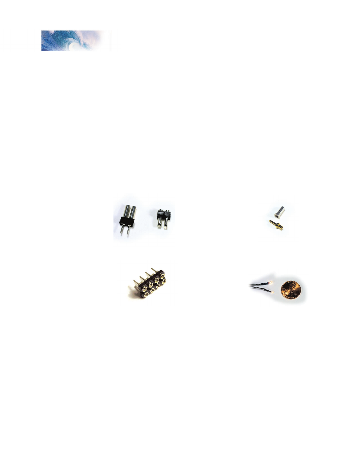
P.N. 810022
1.3mm 1.5 Volt Micro-bulbs
P.N. 810012
2-pin Micro-connector
P.N. 810123
Pkg. of 4 Eight-pin
NMRA Connectors
P.N. 810058
Pkg. of 10 Single-pin
Micro-Mini Connector
We also recommend the following items to aid your installation:
Micro connectors can be used to facilitate easy separation of items like
speakers from the locomotive. SoundTraxx offers an economical 2-pin
connector (P.N. 810012) and a 10 pack of mini-micro connector pins and
sockets (P.N. 810058).
SoundTraxx P.N. 810123 is an NMRA-compatible 8-pin socket useful for
converting harnessed decoders to a more ‘plug and play’ format.
SoundTraxx offers two sizes of 1.5 Volt micro-bulbs for use with the included
lighting effects. P.N. 810022 is a 1.3mm diameter bulb and P.N. 810024 is a
2.2mm diameter bulb. Bulbs are also available in economical six-packs.
SoundTraxx offers a variety of high quality, miniature speakers suitable for
use with Digital Sound Decoders. Wherever possible, choose the largest
speaker that can be fit into the locomotive.
Tsunami Installation Guide Page 5
Page 9

Installation
Step 1. Select Your Locomotive
If this is the first time you have installed sound in a locomotive, then we
suggest you choose your locomotive carefully. A few simple precautions will
ensure that your first effort produces a great sounding locomotive instead of
an intimidating ball of wires:
• Don’t pick a locomotive whose stall current exceeds the rating of the
decoder.
• Do pick a smooth running locomotive that runs well on straight DC
power. A smooth running mechanism is vital for good throttle control
and enhances the realism of the sound. Dirty, worn out or binding
mechanisms not only overload the decoder, but also will have trouble
starting smoothly and will destroy the illusion created by the AutoExhaust feature if they barely lurch along at half throttle.
• Do start with an engine that is ‘sound-ready’ if possible, such as an
engine with predrilled speaker holes. The simpler you can make your first
installation, the better.
• Don’t pick a noisy engine, or one which experiences some arcing or
sparking when in operation. The best sound will come from locomotives
powered with can motors. Older, open-frame motors may produce an
offensive, interference sound.
Tsunami Installation Guide Page 6
Page 10
Tsunami Installation Guide Page 7
Installation
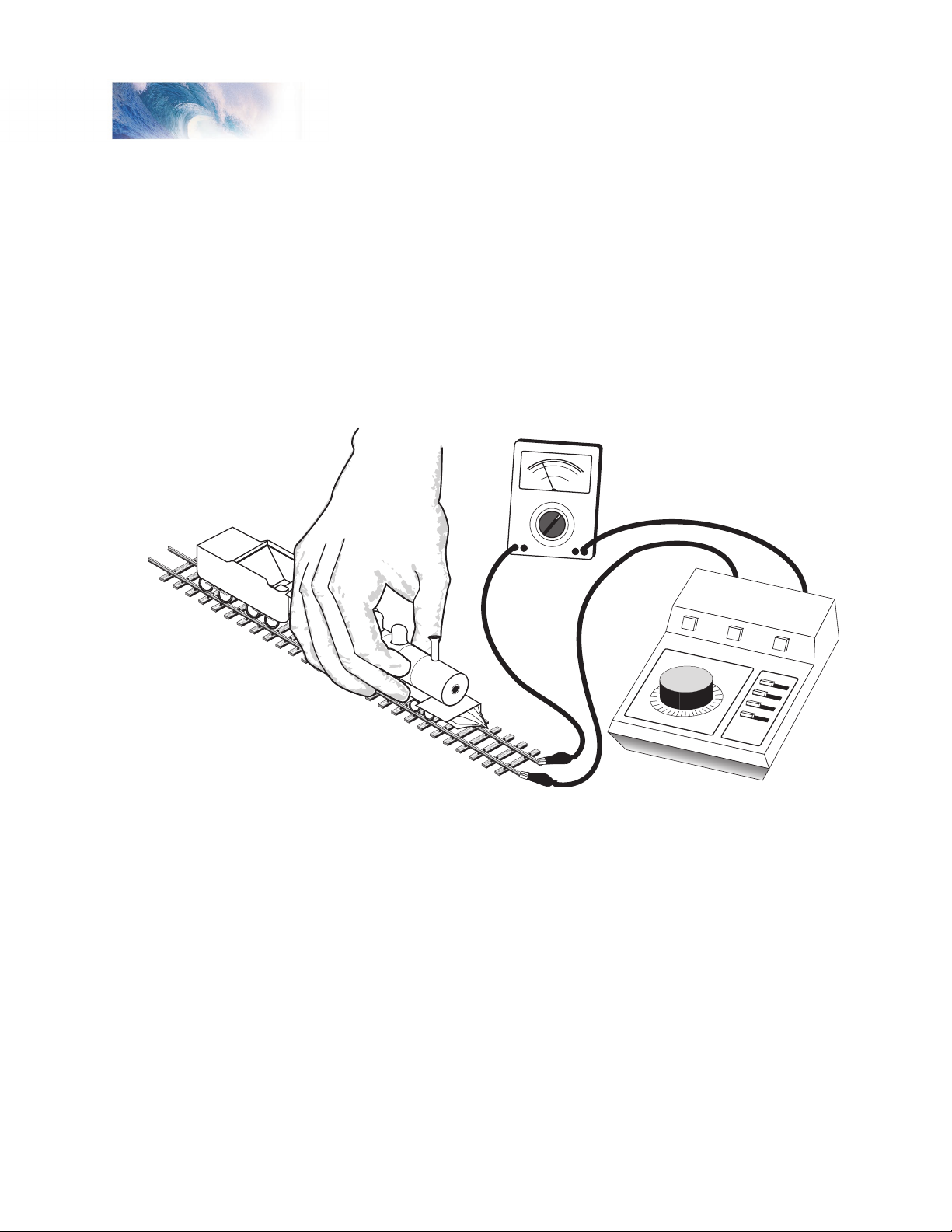
Ammeter
DC Power Pack set to 14V
(12V for N-Scale)
Step 2. Test the Motor Stall Current
Test the locomotive’s stall current to ensure that it is compatible with the
Tsunami model you have selected.
1. Place the locomotive on a section of track powered by a conventional
DC power pack set to the same track voltage as your command station
(typically 12-14 volts).
2. Connect a DC ammeter in series with one of the track feeders as shown
in Figure 1. If your power pack has built in meters, they may be used for
this purpose.
Figure 1 - Testing the Locomotive’s Stall Current
3. While grasping the locomotive to prevent it from taking off, turn the power
pack on.
4. Stop the motor from turning by firmly pushing it down into the track or
grabbing hold of the flywheel.
5. To ensure the most accurate measurement, be sure that the power pack
voltage remains at the voltage set in Step 1 of this test.
6. Measure the current the locomotive is drawing while the motor is stalled.
This is the stall current and must be less than the decoder’s rated
capacity.
Tsunami Installation Guide Page 7
Page 11
Installation
Backup Light
Right Rail Pickup
usually connects
to locomotive frame
Headlight
Speake
r
Left Rail Pickup
usually connects
to tender fram
e
Blue
Whit
e
Motor (+) Lead
Motor (-) Lead
Black
Yellow
Purple
Blue
Orange
Gray
Red
Digital
Sound
Decode
r
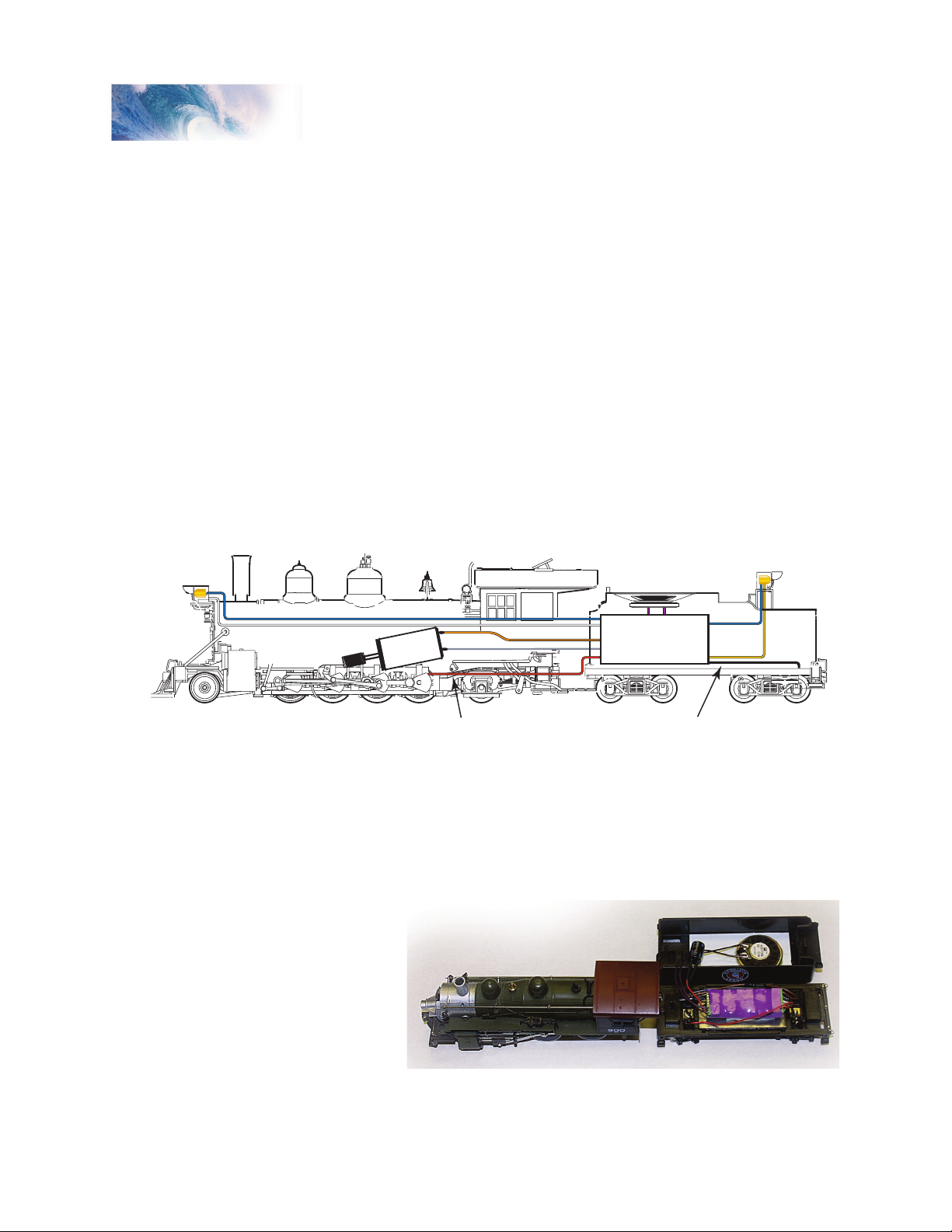
Step 3. Plan the Installation
You should give some thought to where the installation of the various DSD
components will be within the locomotive before you get started. Provide
ventilation for the decoder if possible, mounting the decoder so that some
airflow can occur. Also, mount the decoder away from other heat sources,
such as the motor or lamps to reduce the chance of overheating. If you can,
mount the decoder so that the ‘flat’ side is against a metal chassis or weight.
This will further help to dissipate heat. Always, always provide a proper baffle
(enclosure) for the speaker. Lack of a speaker baffle is the leading cause
of poor sound quality or low volume. Finally, make sure to use the largest
speaker that you can fit, as a bigger speaker will provide more volume and
deeper bass.
Figure 2 shows a typical Tsunami installation in a die-cast locomotive.
Following as many of the guidelines above as possible, we’ve mounted the
flat side of the decoder against the tender shell to help dissipate some heat.
The speaker is mounted up under the coal load, and the decoder is not
mounted near the motor or lamps.
Figure 2 - Typical Steam Sound Installation
In Figure 3, the speaker is mounted on a deck plate fabricated from sheet
styrene pointing up through the coal load. The tender shell acts as a baffle
for the speaker. The plastic coal load can be perforated with small holes
made with
a pin vise
or hand
drill. The
decoder is
mounted to
the weight
on the
floor of the
Tsunami Installation Guide Page 8
tender.
Figure 3 - A typical speaker installation using the tender as
the speaker enclosure.
Page 12

Tsunami Installation Guide Page 9
Installation
Backup Light
Headlight
Left Rail Pickup
Speaker in fuel tank or
under fan grills
Blue
Blue
Whit
e
Motor (+) Lead
Red
Gray
(
Motor (-) Lead)
Orange
Blac
k
Yellow
Purple
Red
JUMPER WIRE BETWEEN TRUCKS
Digital
Sound
Decoder
When planning a diesel installation the same rules apply. In general you
want to draw heat away from the decoder by mounting the flat side against a
metal chassis or weight, or providing additional airflow if possible. This may
not always be an option, so don’t mount the decoder above the motor which
generates it’s own heat and will cause the natural tendency of the decoder to
get warm during operation to be accelerated.
Figure 4 - Typical Diesel Sound Installation
Figure 4 shows a typical Tsunami installation for a diesel locomotive. In this
instance, the speaker is mounted in the fuel tank, with the module itself under
the fan grills. If the fan grills are open, some airflow can be created by drilling
some small holes in the bottom of the frame without compromising the sound
quality since the speaker is isolated in the fuel tank (a natural baffle!). If the
chassis is metal, the flat side of the decoder can be mounted against it to
help dissipate some heat. Like the steam installation on the previous page,
the decoder is not mounted near the motor or lamps.
Figure 5 - A typical speaker installation in a
powered diesel locomotive. Note baffle and fuel tank compartment.
Tsunami Installation Guide Page 9
Page 13

Installation
Speaker Considerations
You will want to use the largest speaker possible to get the best volume and
bass response.
The decision most critical to the success of your installation will be where to
put the speaker. Obviously, the ‘where’ of speaker installation will depend
on the size and type of the locomotive. But when considering the speaker’s
location, remember that the volume of the speaker will be greatly enhanced
when the speaker is fitted into a small airtight enclosure with the front of the
speaker open to surrounding air. The reason for this is simple: in order to
generate any appreciable sound, the speaker must develop air pressure.
Without an enclosure, an opposite pressure behind the speaker cancels
any pressure developed by the front of the speaker. The enclosure isolates
the front and back surfaces of the speaker, thereby increasing the sound
pressure and hence, the volume. It is critical therefore to make sure you seal
these baffles well; any holes or loose seams will diminish the results and in
some cases cause unwanted vibrations.
Additionally, the enclosure must be sized proportionally to the speaker such
that the volume of air enclosed is several times larger than the speaker
diameter. As a rule of thumb, for small speakers, the minimum for the length,
width and height should be equal to the speaker diameter. Unfortunately,
as space is limited in most models, this is only a general guideline, and
exceptions can and must be made in many circumstances.
HOWEVER, the use of a proper speaker enclosure cannot be over
emphasized and failure to use one is almost always the cause for poor sound
quality.
In many cases, the tender of a steam loco tender can serve as the speaker
enclosure. In this case, mount the speaker facing down through an opening
in the tender floor or up through an opening in the coal load as shown in
Figure 2. For diesel models, the fuel tank makes a good natural enclosure.
Alternatively, up under the fan grills or in the cab can be good locations.
SoundTraxx offers a variety of high quality, miniature speakers suitable for
use with the Tsunami Digital Sound Decoders (see the table on page 12) as
well as baffle kits for some of the more popular models.
Figure 6 - SoundTraxx Snap-together Baffle Kits
Tsunami Installation Guide Page 10
Page 14

Tsunami Installation Guide Page 11
Installation
Home-made Baffle from Sheet Styrene Baffle Fabricated from Bottle Cap
SoundTraxx currently offers four sizes of snap-together speaker baffle kits
for use with SoundTraxx speakers. P.N. 810107 is designed for use with
a 3/8” round speaker, P.N. 810108 fits a 1/2” round speaker, P.N. 810109
accommodates a 3/4” round speaker and our P.N. 810110 is perfect for a 1”
round speaker.
If you wish to fabricate your own, a speaker enclosure need not be fancy and
can be built from sheet styrene, bass wood, and even cardboard in a pinch!
A 35mm film canister usually produces excellent results, as does a pill bottle
or the cardboard tube center of a roll of paper towels.
Figure 7 - Other Types of Speaker Enclosures
The Figure 7 illustrates some home-made speaker baffles. With a little
creativity, you’ll be surprised at how many baffles you can create from sheet
styrene or from items just laying around the house or workbench.
Choosing the Right Speaker
While each and every SoundTraxx sound decoder is packed with awesome
digital sound, the reality is that without a good speaker, you won’t hear that
great sound. The table on the following page should help you choose the
best possible speaker to match to your particular installation.
In general, a larger speaker will provide better sound; therefore, try to choose
the largest possible speaker for your installation. Once you have determined
what physical space is available, look at the chart below to determine which
speakers will fit. Remember to consider the size of the speaker baffle as well.
If you have more than one choice available, look at the frequency response
of the speaker and choose the one with the lower number.
Using Tsunami with Multiple Speakers
In most cases, one speaker properly installed and baffled will provide more than
enough volume for the average model. In cases where size constraints may
make it desirable to use multiple smaller speakers instead of one, care should
be taken to observe the following:
Tsunami’s amplifier is designed to drive an 8 ohm load. If you choose to use
Tsunami Installation Guide Page 11
Page 15

Installation
Part
Number
R = Round O = Oval
810083
810089
810053
810054
810055
810056
810087
810057
810059
810112
810113
810103
810078
810084
0.18
0.19
0.13
0.20
0.65
0.70
0.84
0.96
1.50
0.19
0.28
0.32
0.50
1.10
R
R
R
R
R
R
R
R
R
O
O
O
O
O
0.20
0.10
0.20
0.20
0.20
0.30
0.50
1.50
3.00
1.00
1.00
1.00
1.00
2.00
0.39
0.59
0.80
1.10
1.50
2.00
2.50
3.00
4.00
1.00x0.56
1.38x0.63
1.56x0.78
1.12x1.57
1.50x2.50
Diameter
(in.)
Depth
(in.)
Frame
Style
Max. Input
Power (Watts)
8
8
8
8
8
8
8
8
8
8
8
8
8
8
Impedance
(Ohms)
750-3.5K
540-20K
600-7K
550-6K
700-4K
500-4K
330-4.5K
280-5K
160-12K
750-3.5K
500-12K
550-12K
350-12K
230-20K
Frequency
Response
SoundTraxx Speaker Comparison Chart
multiple speakers wire them according to the directions on page 23 so as not
to exceed this load. If not wired correctly, multiple speakers can overload the
amplifier.
Note: Do not use Tsunami with speakers whose (total) impedance is less than
8 ohms. Doing so may result in erratic operation or even component failure!
Tsunami Installation Guide Page 12
Decoder Considerations
It is normal for the DSD to get warm after periods of extended operation and
its thermal overload protection will shut down the audio amplifier if it gets too
warm. Therefore, it is important to install the decoder in a location where it
can dissipate the most heat. Avoid placing the decoder near heat sources
such as the motor or lights wherever possible.
Lighting Considerations
Each Tsunami is equipped with four function outputs that are intended to
drive headlight, backup light and special effect lights. The outputs can be
independently programmed for a multitude of Hyperlight effects and may be
used in a variety of ways. Each output is rated for 100mA.
Do not exceed this rating! Be sure that the combined current of all
lights as well as the motor stall current measured in Step 2 does not
exceed the decoder’s current rating.
Page 16

Tsunami Installation Guide Page 13
Installation
Single-pin
Micro-Mini Connector
Eight-pin
NMRA Connector
MC2 2-Pin
Microconnector
The DSD lighting outputs may be used with 12-16 volt incandescent lamps,
LEDs or 1.5-volt micro-bulbs. For more on lighting outputs, see pages 25
and 26.
Other Considerations
Finally, you will need to decide whether or not to hardwire the electrical
connections or use a plug-able connector. A connector will allow you to easily
separate the components for storage, painting and service easier but also
opens the possibility of accidentally damaging the decoder by reversing
the connector during reassembly. Hardwiring the decoder will prevent this
possibility at the expense of making separation more difficult.
Figure 8 - Miniature connectors make installation easier.
After you have fully read the installation instructions that came with your
decoder, we suggest you draw yourself a schematic showing all connections
between the DSD and various sub-components. This will help you determine
which type of connector is best suited for your needs.
Tsunami Installation Guide Page 13
Page 17

Installation
Left-hand Rail Pickup
Forward
Right-hand Rail Pickup
Motor
Step 4. Isolate the Motor
The two motor brush connections must be electrically isolated so they are
driven exclusively by the DSD motor outputs. We’re not kidding about this!
Nowadays, many locomotives are being designed and sold as ‘DCC-ready’.
Unfortunately, this means different things to different manufacturers, but it
generally means that this step has been taken care of for you. In the case of
a ‘DCC-ready’ locomotive, follow the instructions on page 27.
Failure to properly isolate the motor will damage your decoder and turn
it into an effective, but short-lived smoke generator!
Begin motor isolation by removing the body shell from the locomotive and in
the case of a steam locomotive, the tender shell as well.
Before you proceed further, it is important to carefully examine the
locomotive wiring and determine where each wire goes and what it does.
The manufacturer’s assembly drawings may be useful here or you may elect
to create your own wiring diagram. In particular, you will need to identify the
connections to the left and right power pickups as well as the (+) and (-)
motor connections. Note: for N, HO, and S scale locos, the positive motor
connection is the one connected to the right rail (engineer side) power
pickup.
Figure 9 - Conventional DC Power Pickups
Disconnect all wires leading to both motor terminals. Note that some motor
brush connections are made using a spring contact to the chassis. In such
cases, it will be necessary to remove or modify the spring contact as well.
Be aware that some locomotives may make contact between the motor and
frame only when the body is reinstalled.
Tsunami Installation Guide Page 14
Page 18

Tsunami Installation Guide Page 15
Installation
Next, verify that each motor terminal is electrically isolated from the left and
right rail pickups using an ohmmeter or continuity tester:
1. With your meter set to the ohms scale, touch both meter probes together
and note that the meter indicates 0 ohms (short circuit). You don’t want to
see this indication again!
2. Touch one of the probes to one of the motor brush terminals.
3. Touch the other probe to the locomotive frame, then the left rail power
pickup wire, and finally to the right rail power pickup wire.
4. Move the first probe to the other motor brush terminal and repeat the
tests. If all tests indicate an open circuit, the motor is properly isolated.
Do not proceed further until this is done.
You will also need to disconnect the wires leading to any lights you wish to
use. Using an ohmmeter, check that each lamp lead is electrically isolated
from the frame as well as the left and right rail pickups.
Tsunami Installation Guide Page 15
Page 19

Installation
Styrene
in sub-deck
Cut hole diameter
to slightly less than
speaker diameter.
Pe
rforate coal load
with #55 drill.
Cross section of plastic tender
with molded coal load.
Remove inside walls
and slope sheet if needed.
Opening in deck
should be slightly smaller
than speaker diameter
Optional wooden
retaining boards to
bu
ild up height.
Step 5. Modify the Tender or Body Shell
In the case of a steam locomotive, you will probably be mounting the speaker
facing down on the tender floor or facing up in the coalbunker. You may
need to cut an opening in the tender floor for the speaker. A series of small
holes can be easily drilled and will work as well as one large hole provided
the open area is at least one half the area of the speaker cone. In either
case, there should be no openings outside or larger than the speaker cone
itself. If the locomotive is plastic and you will be drilling holes in the coal load,
drill them at slight angles and they will appear nearly invisible.
Figure 10 - Examples of Some Tender Modifications
Tsunami Installation Guide Page 16
In the case of a diesel model, you may need to mill out some of the weight
Page 20

Tsunami Installation Guide Page 17
Installation
Mill out the metal fuel tank and create styrene
deck plate for speaker to mount.
Fabricate styrene baffle
Oval Speaker
Replace factory fan grills with
open grills (available as aftermarket
detail parts)
Speaker
Speaker
Gasket
Deck
Plate
in the fuel tank or replace the model’s fan grills with some open-grill detail
parts. Figure 11 shows some of the modifications you might make in a diesel
installation. By milling out some of the weight in the fuel tank an enclosure
is made for the speaker. You will need to fashion a mounting plate for the
speaker and seal it well.
If you place the speaker under open fan grills, you may still wish to baffle the
speaker rather than use the body as the baffle, as it may be difficult to seal
the chassis well enough to achieve the results you want.
Figure 11 - Diesel Modifications
Tsunami Installation Guide Page 17
Page 21

Installation
Step 6. Secure the Speaker in Place
Once work is complete and the speaker has been fitted in place, it must
be secured tightly to the enclosure. For the best sound, an airtight seal is
needed around the speaker edge.
We have found the best way to hold the speaker in place is to use our special
speaker gaskets. The gaskets have adhesive on both sides. Peel off the
backing with a pair of tweezers or the blade of a knife and mount one side to
the rim of the speaker, making sure not to stick the gasket to the cone itself.
Remove the other backing and mount your speaker in the desired location.
Figure 12 - Applying the Speaker Gasket
SoundTraxx has four different gasket sizes available in packages of four:
P.N. 810118
3/4” round gaskets for use with our 3/4” diameter speaker (P.N. 810053)
P.N. 810119
1” round gaskets for use with our 1’ diameter speaker (P.N. 810054)
P.N. 810120
20x40mm gaskets for use with our oval speaker (P.N. 810103)
P.N. 810121
14x25mm gaskets for use with our smallest oval speaker (P.N. 810112)
Another option is to use silicone RTV - it provides the airtight seal needed
and unlike epoxy or other hard glues, allows the speaker to be readily
removed in the future. Be careful that you don’t get any RTV onto the
speaker diaphragm, as this will severely distort the sound quality!
Tsunami Installation Guide Page 18
Page 22

Tsunami Installation Guide Page 19
Installation
Step 7. Install the Cam
(Optional, Steam Only)
If you are intending to synchronize the steam exhaust chuff using a
mechanical cam switch, you have a little more work to do. Otherwise, if you
are planning to use the Tsunami’s Auto-Exhaust feature, you may skip this
step.
SoundTraxx offers its P.N. 810038 Exhaust Cam Kit as an easy to install
alternative to traditional axle mounted sound cams. The Exhaust Cam
set provides nine different synchronizer disks of varying diameters and
configurations. Installation is straightforward and unlike the traditional sound
cam, has the advantage that the drive wheel does not need to be removed
from the axle.
Begin by selecting the synchronizer disk pattern appropriate for your engine:
2-Cylinder Steam Locomotives
In all conventional 2-cylinder steam engines,
use a synchronizer disk with 4 foil segments.
You can achieve the proper prototypical exhaust
chuff timing by aligning the foil strips of the
synchronizing disks to the crank pin on the driver
wheel.
Articulated Steam Locomotives
Articulated engines come in two flavors, simple
and compound. On simple articulated engines,
the cylinders on the front and rear are the same
size. On compound engines, one set of cylinders
is considerably larger than the second set.
For compound articulated engines, 4 chuffs per
driver revolution is correct. Install the same as for
regular locomotives.
For simple articulated engines, a synchronizer
disk is available that provides 8 chuffs per driver
revolution.
Geared Locomotives
Geared engines require a larger number of
chuffs due to multiple cylinders and gearing of
the drive wheels. Due to the large number of
contacts required for each wheel revolution, it is
usually impractical to achieve the prototypically
correct number of exhaust chuffs per revolution.
The Shay disk (supplied with the Exhaust Cam set) will provide a
reasonable compromise. Optionally, you may elect to use the AutoExhaust feature.
Tsunami Installation Guide Page 19
Page 23

Installation
1. Cut and trim
disk to fit
2. Glue disk to
uninsulated
driver
3. Solder disk
hub to axle
Install the Synchronizer Disk
Carefully measure the diameter of your locomotive’s driver axle. Drill a hole
of the same diameter in the center of the synchronizer disk you plan to use.
Note: the thin disk material will be easier to drill if you temporarily adhere it
to a smooth wood block with a water soluble glue. The disk can be separated
from the block by soaking in water after the drilling operation is complete. Be
sure to use a sharp drill to get a clean burr-free hole.
Once the hole is drilled, check that there is still enough foil at the ‘hub’ to
connect all the spokes together. If not, you will need to use a synchronizer
disk with a larger hub.
Cut the disk out with a sharp pair of scissors, and trim the disk diameter to
slightly less than the locomotive drive wheel diameter. This is important
as clearance will be needed to clear turnout frogs, guard rails, and other
trackwork features.
Using the scissors, make a single radial cut in the disk between the foil
spokes from the outer edge to the center hole. Slip the disk over the drive
axle with the insulated side facing against the drive wheel. Check for a
correct fit and make any needed adjustments. The disk should fit flush
against the drive wheel and there should be a close fit against the axle. Once
you are satisfied with the fit, glue the disk against the non-insulated drive
wheel with epoxy or contact cement. You will need to electrically connect the
synchronizer disk to the drive wheel axle. This is best done by soldering the
axle to the foil hub. Alternatively, you may use conductive paint to make the
connection.
Figure 13 - Synchronizer Disk Installation
Install the Cam Wiper
Using the spring wire supplied with the Exhaust Cam set, fabricate a contact
wiper. Bend the wire to match the pattern of Figure 14 using a pair of needle
nose pliers.
Solder the wiper to the small printed circuit board base as shown in Figure
Tsunami Installation Guide Page 20
14. Keep the spring wire as long as possible to provide flexibility. If the wire is
too short, it will rub against the synchronizer disk with excess force causing
premature wear and possible binding.
Page 24

Tsunami Installation Guide Page 21
Installation
1. Bend spring wire
to this shape.
2. Solder to
mounting PCB
Figure 14 - Cam Wiper Fabrication
Temporarily mount the insulated side of the wiper base to the locomotive
frame such that the wiper end barely rubs against the synchronizer disk
and does not touch any other part of the locomotive. Referring to Figure 15,
adjust the spring wire so that the contact point is centered directly below the
axle and its plane is parallel with the top of the rail. Once the wiper has been
properly adjusted, move the wiper base until the spring wire is deflected by
about 1/32” to 1/16” and secure the base in place with epoxy.
Figure 15 - Contact Wiper Alignment
Tsunami Installation Guide Page 21
Page 25

Installation
Speaker
Minus (-)
(Purple)
Headlight (White)
Backup Light (Yellow)
Function Common (Blue)
Function 5 Output (Brown)
Function 6 Output (Green)
Motor - (Gray)
Motor + (Orange)
Left-hand Rail Pickup (Black)
Right-hand Rail Pickup (Red)
Speaker
Plus (+)
(Purple)
Capacitor
Exhaust Cam
(Optional)
(Tan)
Step 8. Install and Wire the Decoder
(Non DCC-Ready Models)
Begin by securing the decoder in place using double-sided foam tape.
Temporarily refit the tender or body shell to ensure that adequate clearance
still exists.
When wiring the decoder, trim all wires to reduce unnecessary lead length.
This will not only give your installation a neater appearance but also prevent
wires from interfering with the drive mechanism and getting pinched when
closing up the boiler or tender shell.
To ensure long-term reliability, solder all connections and insulate with heatshrink tubing such as SoundTraxx P.N. 810036.
Make your connections according to the Master Wiring Diagram and the
figures that follow.
Tsunami Installation Guide Page 22
Track Connections
Figure 16 - Master Wiring Diagram
Connect the RED wire of the decoder’s wire harness to the right (engineer’s
side) track power pickup and the BLACK wire of the decoder’s wire harness
to the left track power pickup.
Motor Connections
Connect the ORANGE wire of the decoder’s wire harness to the motor’s (+)
terminal and the GRAY wire of the decoder’s wire harness to the motor’s (-)
terminal.
Page 26

Tsunami Installation Guide Page 23
Installation
Forward
Left-hand Rail Pickup
Right-hand Rail Pickup
Motor
Gray
Motor Negative (-)
Orange
Motor Positive (+)
Decoder
Figure 17 - Track and Motor Connections
Speaker Connections
Connect the decoder’s PURPLE speaker (+) wire (pin 12) to one of the
speaker terminals. Connect the other PURPLE speaker (-) wire (pin 10) to
the other speaker terminal. Note: Tsunami does not need a capacitor to
be wired in series with the speaker as required by some other SoundTraxx
decoders.
Note: the polarity of the speaker
terminals is only important when
using multiple speakers (see
below). If you have installed
multiple speakers, make sure they
are phased properly, i.e., positive
lead to positive lead and minus lead
to minus lead of each speaker.
On smaller speakers, solder the
wires to the outside edges of the
solder pads as shown in Figure 18.
Figure 18 - Soldering to
the Speaker Terminals
Wiring Multiple Speakers
When wiring multiple speakers, it is very important to observe speaker polarity as
noted above. If a speaker is wired backwards with respect to another speaker,
each speaker will produce a sound wave that is 180 degree out of phase with
the other. The two sound waves will effectively cancel each other out resulting
in a diminished volume level! If the speaker does not have polarity markings
on their terminals, wire like terminals to like terminals (i.e., left terminal to left
terminal). If in doubt, try swapping the polarity of one speaker and see if the
sound improves or worsens.
Tsunami is designed to drive an 8 ohm load. You must properly wire multiple
speakers according to the directions that follow so as not to exceed this load.
Tsunami Installation Guide Page 23
Page 27

Installation
+
-
+
-
+
-
+
-
8 Ohms
Speaker
Minus (-
)
Speaker
Plus (+)
Note: This illustration shows how to correctly wire four 8-ohm
speakers in a series/parallel combination, resulting in a total load of 8 ohms.
+
-
+
-
16 Ohms
Note: This illustration shows how to correctly wire two 8-ohm
speakers in series, resulting in a total load of 16 ohms.
Speaker
Minus (-
)
Speaker
Plus (+)
In Figure 19, two speakers are wired in series, with the positive speaker lead
connected to the positive speaker terminal, the negative speaker lead to the
negative terminal and the remaining speaker terminals connected to each other as
shown. When wired in series, the ohms of the speakers are essentially doubled,
making 16 ohms. Note that larger numbers equal a lesser load, therefore 16
ohms is a lesser load than 8 ohms.
In Figure 20, four speakers are wired in a series/parallel configuration. Each
pair of speakers wired in series equals 16 ohms, but since wiring in parallel will
halve the ohms, the total is still 8 ohms.
Figure 20 - Wiring Four 8-Ohm Speakers in Series/Parallel
Figure 19 - Wiring Two 8-Ohm Speakers in Series
Tsunami Installation Guide Page 24
Page 28

Tsunami Installation Guide Page 25
Installation
1.5V Microbulbs
Forward
Lamp
Reverse
Lamp
560 ohm
Resistor
560 ohm
Resistor
WHITE
YELLOW
FUNCTION COMMON
BLUE
12-16V Lamps
WHITE
Reverse
Lamp
Forward
Lamp
YELLOW
FUNCTION COMMON
BLUE
Lighting Connections
12-16V lamps can be directly wired to the function outputs as shown in
Figure 21.
Figure 21 - Wiring the Decoder for 12 Volt Lamps
If you are driving 1.5V microbulbs with your Tsunami decoder, it will be
necessary to wire a small current-limiting resistor in series with each of the
lamps to prevent them from burning out (see Figure 22).
A separate resistor must be used for each bulb even if they are connected
to the same output. A 560-ohm, 1/4W resistor is recommended for use with
SoundTraxx P.N. 810022 or 810024 microbulbs, however, you may need to
adjust the resistance value to get the desired brightness depending on the
output voltage of the command station. Lower resistance will increase the
brightness of the lamp.
Figure 22 - Wiring the Decoder for 1.5 Volt Lamps
1. To wire the Headlight, connect one end of the bulb to the decoder’s
WHITE wire. Wire the other bulb lead to the decoder’s BLUE wire.
2. To wire the Backup light, connect one end of the bulb to the decoder’s
YELLOW wire. Wire the other bulb lead to the decoder’s BLUE wire.
If you use Functions 5 and 6 for lighting effects:
3. To wire the Function 5 output, connect one end of the bulb to the
decoder’s BROWN wire. Wire the other bulb lead to the decoder’s BLUE
wire.
Tsunami Installation Guide Page 25
Page 29

Installation
FUNCTION COMMON
BLUE
Forward
Lamp
Reverse
Lamp
680 ohm
Resistor
WHITE
YELLOW
Cathode (-)
680 ohm
Resistor
Cathode (-)
LEDS
4. To wire the Function 6 output, connect one end of the bulb to the
decoder’s GREEN wire. Wire the other bulb lead to the decoder’s BLUE
wire.
Any outputs not used can be left disconnected, but you should cut off and
insulate the ends of the wires so they do not come in contact with locomotive
or locomotive wiring.
Using LEDs
Tsunami decoders may be used with LEDs, which also require a resistor to
be wired in series, typically about 680-ohms, 1/4W. Unlike lightbulbs, LEDs
are sensitive to polarity. The minus (-) cathode end of the LED (the shorter of
the two leads) is connected to the function output and the plus (+) anode end
is connected to the decoder’s BLUE (function common) wire.
1. To wire the Headlight, connect the cathode end of the LED to the one
lead of the resistor. Wire the other resistor lead to the decoder’s WHITE
wire. Wire the anode LED lead to the decoder’s BLUE wire.
2. To wire the Backup light, connect the cathode end of the LED to one lead
of the resistor. Wire the other resistor lead to the decoder’s YELLOW
wire. Wire the anode LED lead to the decoder’s BLUE wire.
If you use Functions 5 and 6 for lighting effects:
3. To wire the Function 5 output, connect the cathode end of the LED to
one lead of the resistor. Wire the other resistor lead to the decoder’s
BROWN wire. Wire the anode LED lead to the decoder’s BLUE wire.
4. To wire the Function 6 output, connect the cathode end of the LED to
one lead of the resistor. Wire the other resistor lead to the decoder’s
GREEN. Wire the anode LED lead to the decoder’s BLUE wire.
Figure 23 - Wiring the Decoder for LED Lamps
Tsunami Installation Guide Page 26
Exhaust Cam Connections (steam only)
Connect the TAN wire from the 3-pin Speaker/Cam harness of the DSD to
the exhaust cam wiper switch. The decoder is factory-programmed to operate
using the Auto-Exhaust feature. If you wish to use an exhaust cam, you must
enable the cam-synchronized exhaust by setting CV 112 to 128.
Page 30

Tsunami Installation Guide Page 27
Solder wires to ‘cup’ side
of 8-pin connector
Motor Right (Orange)
Rear Light (Yellow)
Not Used
Left
Rail (Black)
Right Rail (Red)
Fu
nction Common (Blue)
Headlight (White)
Motor Left Gray
Pin 1 Pin 8
Installation
Installing Tsunami in a DCC-ready Locomotive
If your locomotive is wired with an NMRA-compatible 8-pin socket, you
may solder a mating connector to the DSD’s wire harness, which will allow
you to easily install the decoder by simply plugging the connector into the
socket, with the exception of the speaker and cam connections. SoundTraxx
offers P.N. 810123, which is a package of four connectors that meet NMRA
specifications. Wire the connector as follows:
Solder the wires from the sound decoder to the cup side of the connector
as shown in the Figure 24. Speaker and cam wires are not soldered to this
connector.
1. Wire the decoder according to the illustration. Before plugging in the
decoder, we highly recommend you perform a simple test on the socket
itself to ensure it is properly wired. Never assume this socket has been
wired correctly at the locomotive factory!
Tsunami Installation Guide Page 27
2. Remove the ‘dummy’ plug from the NMRA socket.
3. Using an Ohmmeter, test the motor connections by touching one probe
to Pin 1 and the other to Pin 8. You should see no response from the
meter. Now touch one probe to Pin 1 and the other to Pin 4. Again, you
should see no response. Repeat this procedure with Pin 5 and Pin 8,
then Pin 5 and 4.
4. Now test the headlight connections by repeating the above procedure
with Pins 8 and 2, Pins 8 and 6 and Pins 8 and 7.
5. Continue the test with Pins 4 and 2, Pins 4 and 6, and Pins 4 and 7.
Remember, you should see no response from the Ohmmeter!
6. Now plug the newly wired connector into the socket with the orange wire
at pin 1 on the manufacturers circuit board. Most manufacturers have
labeled the sockets with pin 1 or pin 8 (at a minimum). Once you have
plugged in the 8-pin connector, you will still need to wire the speaker and
cam according to the instructions for a non DCC-ready decoder.
Figure 24 - NMRA 8-Pin Connector Wiring Code
Page 31

Pin1
Pin 2
Pin 3
Pin 4
Pin 8
Pin 7
Pin 6
Pin 5
Pin1
Pin
2
Pin
3
Pin
4
Pin
8
Pin 7
Pin
6
Pin
5
Test the Motor Connections
Pin 8
Pin 7
Pin 6
Pin 5
Test the Headlight Connections
Pin 1
Pin
2
Pin
3
Pin
4
Pin1
Pin 2
Pin 3
Pin 4
Pin
8
Pin
7
Pin
6
Pin 5
Installation
Figure 25 - Testing the NMRA Socket - Motor Connections
Figure 26 - Testing the NMRA Socket - Headlight Connections
Tsunami Installation Guide Page 28
Page 32

Tsunami Installation Guide Page 29
Installation
Step 9. Test the Installation
Now you are ready for the test track! We recommend your test track be fused
with a fast-blo fuse appropriately rated for your decoder (i.e. 1 amp decoder,
1 amp fuse). Place the locomotive on the track, and turn on power to the
system. Set your controller for locomotive address 3. You should be able
to run the engine in both directions as well as turn the lights on and off with
the function keys. If this is a steam engine, you should also hear the steam
airpump running in the background. Diesel models will idle softly.
If the locomotive does not travel in the appropriate direction, you have
reversed the polarity of the motor brush connection. Turn the power off,
switch the ORANGE and GRAY motor leads and try again. If everything
seems OK at this point, it is time to program the decoder’s Configuration
Variables to get the desired sound and lighting effects. If the decoder does
not respond as expected, first re-check your wiring. If no solution is found,
proceed to the Troubleshooting section of the User’s Guide.
Tsunami Installation Guide Page 29
Page 33

Support
SoundTraxx 90-Day ‘Safety Net’ Warranty
Each SoundTraxx Digital Sound Decoder is tested thoroughly before it is shipped and warranted
to be in good working order and free of manufacturing defects. However, in the event that a
mistake does occur during installation, SoundTraxx will cover the repair under our ‘Safety-Net’
Service Warranty.
If during the first ninety (90) days you damage your Digital Sound Decoder or it fails to operate,
SoundTraxx will repair or replace the system free of charge if:
1. The original sales receipt showing purchase from an authorized SoundTraxx dealer accom
panies the decoder. Receipt must show purchase date to be within the last 90 days Your
original receipt will be returned with your repaired unit.
2. There is no damage resulting from unauthorized repairs or modifications. This includes but
is not limited to:
- Removing the shrink tubing from the decoder
- Drilling or enlarging circuit board holes
- Cutting or trimming the circuit board
3. The Digital Sound Decoder is returned properly packaged, postage paid and insured -
SoundTraxx is not responsible for product lost or damaged in transit.
Exclusions
Onboard locomotive speakers are not covered by this warranty. This warranty does not cover
damage resulting from accidents, fire, floods, or other acts of God.
Limits of Liability
The foregoing shall constitute the sole and exclusive remedy of any owner of this product for
breach of warranty including the implied warranties of merchantability and fitness. IN NO EVENT
SHALL SOUNDTRAXX BE LIABLE FOR SPECIAL OR CONSEQUENTIAL DAMAGES OR FOR
THE REPRESENTATIONS OF RETAIL SELLERS.
Warranty Procedure
1. Return the Digital Sound Decoder with your dated sales receipt, properly packaged, post
age paid and insured. SoundTraxx is not responsible for product lost or damaged in transit.
2. To help expedite your repair, complete a Service Request Form available from our website
at www.soundtraxx.com/support or by contacting our Customer Service Department. This
allows our technicians to more quickly isolate the problem and perform the necessary
repairs.
3. Please make sure you include a daytime phone number in case we should need to contact
you regarding your repair. Your repaired decoder will be returned via UPS Ground (no P.O.
Boxes please!). Decoders being shipped to foreign addresses will be shipped via U.S.
Airmail.
-
-
Important! Return only the Digital Sound Decoder. Under no circumstances should you send
your locomotive (or other model) to us, as we cannot assume any liability for their safe return.
Non-Warranty Repairs
Digital Sound Decoders needing repairs after the ninety (90) day warranty period will be repaired
at prevailing service rates. Rates are published on our website or can be obtained through our
Customer Service Department.
Out-of-Warranty Repair Procedure
To obtain service for Digital Sound Decoders which do not qualify as Warranty Repairs:
1. Return the decoder with your dated sales receipt, properly packaged, postage paid and
insured. SoundTraxx is not responsible for product lost or damaged in transit.
2. To help expedite your repair, complete a Service Request Form available from our website
at www.soundtraxx.com/support or by contacting our Customer Service Department.
3. Please make sure you include a daytime phone number in case we should need to contact
you regarding your repair.
4. Please include a check or money order in U.S. dollars drawn on a U.S. bank according
to the posted rates, or provide a credit card number and expiration date (MC or VISA,
please!). Posted rates include shipping via UPS (no P.O. Boxes please!). Decoders being
Tsunami Installation Guide Page 30
Page 34

Tsunami Installation Guide Page 31
Support
shipped to foreign addresses will be shipped via U.S. Airmail. If no payment is included with
the repair, no work will begin until you have contacted the Customer Service Department.
5. While a rare occasion, in the instance a decoder is determined to be un-repairable, the
system will be returned to you at no charge, with no repairs made. Optionally, the cost of a
standard repair may be applied to the purchase of a replacement decoder. Purchase must
be made directly through the factory.
6. A large percentage of Digital Sound Decoders that are returned are not defective or dam-
aged at all, but have been incorrectly programmed or misused. Digital Sound Decoders
returned that are found to be in good working condition will be returned less a $10.00
charge plus the cost of return shipping. To avoid this, please follow our easy troubleshooting
procedures which can be found in this manual and on our website before returning a sound
system for repair.
For prompt factory service, contact:
SoundTraxx Service Department
210 Rock Point Drive
Durango, CO 81301
Telephone (970) 259-0690
Fax (970) 259-0691
Email: support@soundtraxx.com
Tsunami Installation Guide Page 31
Page 35

©2005 Throttle Up! Corp.
DCC
TM
New Dimensions in Digital Sound Technology
210 Rock Point Drive Durango, CO 81301
(970) 259-0690 Fax: (970) 259-0691 Email: Sales@soundtraxx.com
All Rights Reserved.
COMPATIBLE WITH
THE NMRA DCC STANDARDS
AND RECOMMENDED
PRACTICES
Tsunami Installation Guide Page 32
 Loading...