

Page 1

Tsunami™ Digital Sound Decoder
Steam Sound
User’s Guide
Software Release 1.00
Rev. B 1/13//06
Page 2

Notice
The information in this document is subject to change without notice.
SoundTraxx (Throttle Up!) shall not be liable for technical or editorial errors or omissions contained herein; nor for incidental or consequential dam
ages resulting from the furnishing, performance or use of this material.
This document contains information protected by copyright. No part of this document may be photocopied or reproduced in any form without the
prior written consent of Throttle Up! Corp.
-
Product names mentioned herein may be trademarks and/or registered trademarks of their respective companies.
SoundTraxx, Tsunami, SoundTraxx DCC, Digital Sound Decoder, Dynamic Digital Exhaust, Auto-Exhaust and Hyperlight are
trademarks of Throttle Up! Corp.
Page 3

Table of Contents
All Aboard! ...........................................................................1
Overview ................................................................................................1
Operation .............................................................................2
Using Your Tsunami Digital Sound Decoder ..........................................2
Basics of Programming ......................................................6
Programming the CVs ...........................................................................6
Step 1: Configuring the Address ..........................................................13
Step 2: Configuring the Decoder .........................................................15
Step 3: Configuring the Throttle ...........................................................17
Step 4: Configuring for Consist Operation ........................................... 21
Step 5: Function Mapping ...................................................................24
Step 6: Configuring the Lighting Outputs ............................................30
Sound Programming .........................................................35
Step 7: Modifying the Sound Effects ................................................... 35
Advanced Programming ...................................................50
Step 8: Configuring the Dynamic Digital Exhaust ................................ 50
Step 9: Setting up the Hyperdrive .......................................................57
Step 10: Configuring Tsunami’s Miscellaneous Features ....................61
Troubleshooting ................................................................68
Appendix A - Decimal-Hex-Binary Conversion ...............
Appendix B - List of Configuration Variables .................
71
72
Appendix C - License Agreement ....................................72
Page 4

Overview
All Aboard!
Congratulations on the purchase of your SoundTraxx™ Tsunami™ Digital
Sound Decoder™. This User’s Guide will walk you through the various
aspects of programming your Tsunami decoder, as well as some tips on
troubleshooting. For the power user, the Tsunami Technical Reference will
provide a list of all the CVs available for use with Tsunami decoders and their
exact function and make-up for those who wish to have a complete reference
for advanced programming techniques.
Technical Bulletins and Application Notes covering various topics are also
published from time to time, and these may be downloaded free of charge
from our website at www.soundtraxx.com.
Tsunami Steam Sound User’s Guide Page 1
Page 5

Operation
Using Your Tsunami Digital Sound Decoder
Your SoundTraxx Tsunami has been shipped with all CVs pre-programmed
so you can begin using your locomotive immediately without having to worry
about what adjustments to make. Function Assignments are as follows:
Steam Decoders
Function Key Effect
F0 Headlight/Backup Light/Dynamo
F1 Bell
F2 Whistle
F3 Short Whistle
F4 Steam Release
F5 FX5 Output
F6 FX6 Output
F7 Dimmer
F8 Mute the Sound
F9 Water Stop
F10 Injectors
F11 Brake Squeal/Release
F12 Coupler Clank
Direction Button Johnson Bar
Throttle Exhaust Chuff, Snifter Valve
While these are the default settings, you may wish to make changes to the
function mapping later. For now, simply set your controller to Locomotive 3,
place the locomotive on the mainline and away you go! Now that you have
control of your decoder, let’s see what happens!
Turn on the Lights
Press F0 on your cab to turn on the Headlight. As you turn on the headlight,
the dynamo will ‘spool up’ in an accelerating whine until it reaches full power,
when it will sound more like a soft buzz – can’t have lights without turning on
the generator now can you? Reverse locomotive direction and the headlight
turns off as the backup light turns on.
If you have wired your Tsunami decoder for Functions 5 and/or 6, pressing
these keys will activate these effects. While waiting on a siding, you can
press F7 to dim the headlight for an oncoming train.
Ring the Bell
Engineers are required to ring the bell during yard movement. To ring the
bell, press F1 on your cab. This is an on/off function, i.e. once on, the bell will
continue to ring until you turn it off. Press F1 again to turn it off.
Tsunami Steam Sound User’s Guide Page 2
Page 6

Tsunami Steam Sound User’s Guide Page 3
Operation
Whistle Signals
Note: � = Short Blast — = Long Blast
— — � — Approaching Grade Crossing. (Hold final blast until crossing
is reached.)
�
— Approaching a bridge or tunnel
� Stop, set brakes
— — Release brakes and proceed forward
� � � Backup
� � � � Request signal from Trainman
— � Warning whistle, used when approaching points where
view is obstructed.
Blow the Whistle
Engineers are required to blow various whistle signals to warn of the
approaching train as well as notify both passengers and train crew to the
planned movement of the locomotive. Some of these are signals for grade
crossings, stopping, moving forward, backing up and more.
Learning and using the various whistle signals can add a lot of fun to your
operating sessions! Some of the more common signals are indicated here.
To activate the Whistle, press F2 on your cab: the longer you press the key,
the longer the whistle will blow. While this allows you to make short or long
signals, F3 is designated as a ‘short’ whistle so your shorts will have that
nice, crisp, ‘toot’ regardless of how responsive your cab controls are…try a
grade crossing whistle!
Blow Down the Boiler
If your steam engine’s been sitting in the station awhile, there’s bound to be
some particle buildup in the boiler. Press the F4 key to open the blowdown
valve and blow out the sediment. Press the F4 key again to close the
blowdown valve.
Automatic Steam Sound Functions
Some sound effects happen in response to an action other than pressing a
function key. The blowers will automatically simmer in the background to help
vent the steam and keep up a good draft.
Airpumps
Brakes on trains operate using air pressure. When the engineer activates
the brakes, he is releasing air pressure, forcing the brake shoes against the
wheels and causing the train to slow down. When the engine stops the air
pressure is build up using a compressor, also called an airpump. The air
pumps will pound out a steadily slowing cadence that simulates the build up
of air pressure in the main reservoir. Deceleration of the locomotive while
applying the brakes will cause the air pump to resume pumping.
Tsunami Steam Sound User’s Guide Page 3
More Automatic Sound Functions on Next Page
Page 7

Operation
Snifter Valve
Just as you start to move the engine, you’ll hear the Pffffffft! of the snifter
valve.
Johnson Bar
Changing the locomotive direction will automatically activate the sound of the
Johnson Bar being thrown one way or the other.
Fireman Fred
Each time the engine is brought to a stop, Fireman Fred may attend to a
randomly selected task (or tasks), including shoveling coal, oiling the side
rods, and more.
Exhaust Chuff and Rod Clank
The exhaust chuff and rod clank sounds are automatically generated
whenever the locomotive is set into motion. Both effects may be optionally
synchronized to a cam (see page 44) and may also be configured to vary
in volume in response to load changes using Tsunami’s Dynamic Digital
Exhaust setting (see page 54).
Activating other Functions and Effects
Depending on the number of function keys provided on your cab, you might
have additional functions immediately available for you to activate.
Mute the Sound
Pressing F8 on all Tsunami decoders will gradually mute all sound effects
- great for a quick answer of the telephone! Pressing it a second time will
allow you to hear the sounds again.
Water Stop
All steam engines require water! The Water Stop initiates a sequence of
events beginning with the fireman opening a rather squeaky water hatch,
followed by the sound of water filling the tender. This effect is activated when
the engine is stopped by pressing F9 and can be stopped by pressing F9
again. If the locomotive is started while the effect is running, the effect will
automatically turn off.
Injector
The injector delivers feed water to the boiler. Pressing F10 on all Tsunami
decoders will turn on the sound of the injector. Pressing it a second time will
turn the injector off.
Brake Squeal/Release
The sound of the brakes squealing is typically heard just before the wheels
of the locomotive stop turning. Pressing F11 when the engine is moving will
initiate a brake squeal effect. Press F11 again to turn this feature off.
Tsunami Steam Sound User’s Guide Page 4
Page 8

Tsunami Steam Sound User’s Guide Page 5
Operation
Coupler Clank
Pressing F12 will activate the coupler clank sound effect, see how well you
can time the effect to the actual coupling of the locomotive to the train!
As you see, no programming is necessary to begin enjoying your DSD!
However… after you have had a chance to play with your decoder for a little
while, you may wish to make some changes such as selecting a new address
or altering a sound effect. The following section will introduce you to CVs and
how and why you might wish to change them.
Tsunami Steam Sound User’s Guide Page 5
Page 9

Basics of Programming
Programming the CVs
What is a CV?
CV stands for Configuration Variable, which is the industry-adopted term
for a decoder’s user-programmable memory locations. CVs allow you to
customize individual decoder properties such as the address, momentum,
throttle response, sound volume and much more. Once a CV has been
programmed, the setting will be permanently remembered even after the
power has been turned off. A CV can be modified as often as necessary by
simply reprogramming it with a new value.
With the large number of CVs available, first inspection of the available
options may cause confusion and little panic! Relax. As you have already
seen the DSD has been shipped with all CVs pre-programmed so you can
begin using your locomotive immediately without having to worry about what
adjustments to make.
The following paragraphs break the sound decoder’s CVs into various
subsystems so it is only necessary to change a few CV’s at a time. As you
become comfortable with it’s operation, move onto a new section and begin
exploring the options and capabilities found there. For more technically
inclined users, detailed information on any CV can be found in the Tsunami
Technical Reference.
Bits and Bytes
One of the most confusing aspects of programming a CV is figuring out what
all the different bits, bytes and x’s found in the various decoder manuals
mean. The problem is compounded further by differences in each command
station manufacturer’s user interface. For users unfamiliar with such terms, a
short math lesson (ugh!) is in order before proceeding:
Each decoder CV stores a numeric value that can be represented in one of
three forms:
Decimal - This is the form everyone is familiar with and we use in our day-today lives. Numbers are represented as a sequence of digits composed of the
numerals 0,1,2,3,4,5,6,7,8, and 9.
Hexadecimal - Also referred to as simply “hex”, this is a more specialized
number representation that, in addition to 0 through 9, also uses the
characters A-F. It has the advantage that a given decimal number can be
more compactly represented. For example, the decimal number 127 converts
to a simple 7F in hex (one less digit). This allows user interfaces with a
limited number of digits (i.e., the LCD on your cab) to display a wider range of
numbers.
Binary - Binary numbers get their name from the fact they use only two
digits 0 and 1 called ‘bits’ and is the fundamental number system used by all
computers including the ones found inside a digital decoder. Because there
Tsunami Steam Sound User’s Guide Page 6
Page 10

Tsunami Steam Sound User’s Guide Page 7
Basics of Programming
bit 7 bit 6 bit 5 bit 4 bit 3 bit 2 bit 1 bit 0
are only two bit values, it takes more digits to represent a number using
binary. The decimal number 127, for example, is written as 01111111 in binary
notation. A ‘byte’ is a binary number made up of eight bits. And a ‘nibble’ is
half a byte or four bits. Really! We didn’t make that up.
Coincidentally, each CV is made up from one byte or eight bits and can store
any number between 0 and 255. Most of the CVs contain a single piece of
data that can be easily represented in any of the three forms, i.e., CV 3, the
acceleration rate, can be loaded with any value from 0 to 255 and it always
affects the same thing - the acceleration rate.
On the other hand, some CVs use individual bits to control different features.
This allows up to eight individual features to be controlled by a single CV and
is done to conserve the number of CVs. As the bit variables can take on only
one of two values (0 and 1) they are usually used for simple variables that
are either On or Off, enabled or disabled or something similar. Unfortunately,
bit variables are difficult to represent in any form other than binary and still
preserve any meaning. Because most DCC system user interfaces don’t use
binary representation, these numbers are the most difficult to work with and
require a tedious series of additions to convert to the decimal or hex form
used by most systems.
We have tried to use the decimal number system in this manual when
describing the proper values to program into a given CV; however, you will
occasionally find values listed in the Technical Reference in binary, hex and
decimal values. Hex numbers can be distinguished from a decimal number
by noting a 0x prefix. Thus 0x10 is the hex version of sixteen and not ten as
one might guess. Binary numbers are represented using a ‘b’ suffix. 100b
is really the number four and not one hundred. To further assist the mathimpaired, we have provided a handy-dandy conversion table in Appendix A
that allows one to quickly convert between decimal, hex and binary.
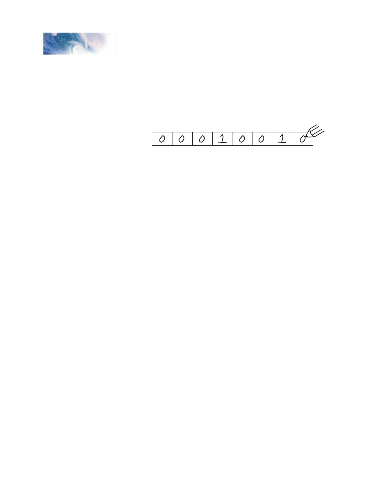
When working with individual bits such as in CV 29, we suggest the following
procedure for determining the correct value to program. Referring to the CV
description, write down the value desired for each individual bit. Consider
for example, the case of CV 29. We would like to set this CV so that speed
tables are enabled and the 28 speed-step mode is in effect. Referring to the
Technical Reference, we see that bit 4 and bit 1 should be set to 1 and all
other bits are cleared to zero. Remembering that we are dealing with binary,
write down the individual bit values and we get:
We then look up the binary value 00010010b in Appendix A and see that it
corresponds to the decimal value 18 (0x12 in hex). This is the value to use
when programming the CV.
Tsunami Steam Sound User’s Guide Page 7
Page 11
Basics of Programming
bit 7 bit 6 bit 5 bit 4 bit 3 bit 2 bit 1 bit 0
When bit is
set to 1, value = 128 64 32 16 8 4 2 1
Therefore: 0 + 0 + 0 + 16 + 0 + 0 + 2 + 0 = 18
If you don’t have the conversion chart available, you can also calculate
the value in the following manner. Reading from right to left, each bit has a
decimal value associated with it, beginning with a 1 and doubling this value
as you go from bit 0 to bit 7. This value is only counted when the bit is a ‘1’.
Looking at the figure below, you can see that using this method, bit 1 has a
value of 2 and bit 4 has a value of 16. Adding these two numbers together
gives the correct decimal value of 18.
Programming Methods
There are two methods for changing the sound decoder’s CVs:
Service Mode Programming - This programming mode usually requires the
locomotive to be placed on a special programming track or connected to a
dedicated programmer. Tsunami is an advanced line of decoders and support
four types of service mode instructions:
Address Mode - Can change CV 1 (Primary Address) only.
Register Mode - Can change CVs 1,2,3,4,7,8 and 29 only.
Paged Mode - Uses a page register to indirectly modify any CV.
Direct Mode - Can directly change any CV.
Operations Mode Programming - Sometimes called ‘Ops Mode’ or
‘Programming on the Main’, this programming mode allows the CVs to be
changed while the locomotive is operating on the layout even when other
locomotives are present. The neat thing about this mode is that the CVs can
be changed in the middle of operation allowing the engineer for example, to
increase the momentum rate of a locomotive after it couples to a train. The
main disadvantage of operations mode programming is that the CV data
cannot be read back to verify its value.
Reading CVs
Certain command stations also allow you to read a CV during Service
Mode Programming, which is useful to verify its current setting. If you have
trouble reading or verifying CVs, the problem may be due to the design
of your command station and not the DSD itself. Tsunami and all other
decoders communicate back to the command station using what’s called an
acknowledgment pulse, which is defined in NMRA RP-9.2.3 as “an increased
load on the programming track of at least 60mA for at least 5ms.” Like most
decoders, the DSD generates the acknowledgment pulse by momentarily
applying power to the motor. You can often visually verify that the Tsunami is
properly responding to your programmer by observing a slight twitch in the
Tsunami Steam Sound User’s Guide Page 8
Page 12
Tsunami Steam Sound User’s Guide Page 9
Basics of Programming
Power In
Po
wer In
Programming Track Output
Programming Tr
ack Output
Programming Track
To Programming Track
COMMAND
STATION
POWER
SUPPLY
COMMAND
STATION
PTB-100
BLACK
BLA
CK
ORANGE
ORANGE
YELLOW
YELLOW
motor shaft when a read or write command is given.
If your DSD is otherwise working properly (i.e., responds properly on the
mainline to speed and direction commands) but your command station
is having troubles reading CV data from the DSD, it may be due to
incompatibilities between the electrical requirements of the DSD (which are
different from conventional decoders due to the added audio circuitry) and
the electrical characteristics of your programming track. In such an event,
we suggest you simply go ahead and program the data into the CVs anyway.
Usually the DSD will accept the data and function properly when placed back
on the main track.
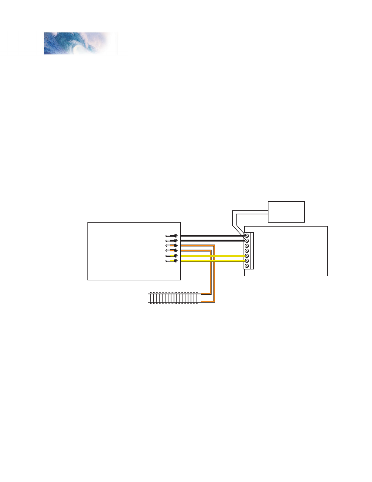
Another option is to use a Programming Track Booster, such as SoundTraxx
PTB-100 (P.N. 829002). The PTB-100 amplifies the programming track
signals to levels that work best with Tsunami. It is easy to install (see below)
and inexpensive. An advantage to using the PTB-100 is that it also provides
short circuit detection and some helpful diagnostics. It works well with all
other SoundTraxx decoders, too.
Figure 1 - General Wiring Diagram for the SoundTraxx PTB-100
Finally, if you continue to experience difficulties, try a different programming
mode. If your system supports it, the best way to program the CVs is
Operations Mode, as it allows you to immediately see or hear the results of
your changes. It is important, however, to realize that not all programming
modes will program all CVs. Additionally, the specific programming mode
you use will depend upon the type of DCC system you are using. Some of
the newer DCC systems can automatically select the proper programming
mode so all you need to do is specify the CV number and its new value. On
the other hand, some systems support only a few of the programming modes
and may restrict which CVs you can program. If in doubt, refer to your DCC
Tsunami Steam Sound User’s Guide Page 9
system’s manual or contact the manufacturer to determine which methods
they support.
Page 13

Basics of Programming
Programming Procedure
As each DCC system is different, the procedure for programming a CV will
vary depending upon the system. Unfortunately, we cannot provide detailed
instructions to cover every command station and have to assume that you
have some level of understanding regarding it’s capabilities and operating
procedures. For specific programming procedures, please consult your DCC
system manual.
Locking and Unlocking CVs
The CV Lock/Unlock is a relatively new feature available in some DCC
decoders which allows you to program a decoder without the danger of
overwriting the programming in another. This especially useful in installations
where multiple decoders are used. For example, if you have installed a
function decoder in addition to the sound decoder, you may wish to lock the
CVs after programming to prevent accidentally programming one or the other.
To use the CV Lock feature implemented in CV 15 and 16, Bit 0 of CV 30
must first be set to 1 (the default value is 0). This is to avoid inadvertently
locking the decoder when the CV Lock feature is not needed.
CV 15 and 16 are used for locking and unlocking the decoder. CV 15 is
the Unlock Code and may be programmed to any value between 0 and
255 regardless of whether the decoder is locked or unlocked. CV 16 is the
Lock Code and may be set to any value between 0 and 7 but only when the
decoder is unlocked. Attempts to program CV 16 with a value greater than 7
will be ignored.
The decoder is unlocked when the value in CV 15 matches the value in CV
16. Otherwise the decoder is locked and can not be programmed in either
operations mode or service mode. Further, a locked decoder can not be reset
to its factory defaults until it is first unlocked. Tsunami decoders are shipped
from the factory with all CVs unlocked, that is, CV 15 and 16 are both set
to 0.
Note that if the decoder is unlocked, changing the value in CV 16 will
instantly lock the decoder. You must then set CV 15 to the same value as
was just programmed into CV 16 to unlock the decoder again.
If you decide to use the CV Locking feature for a multi-decoder installation,
each decoder installed inside that locomotive must first have its Lock Code
in CV 16 set prior to installation of any other decoders. Otherwise, all the
decoders will have the same Lock Code and the feature will not work. The
easiest way to go about this is to first install one decoder and program its
Lock Code. Then install the next decoder and program its Lock Code. Since
the first decoder is now locked it will be unaffected by the programming of
the second decoder (unless you accidentally set the Lock Code of the two
decoders to the same value. If this happens you will need to disconnect one
decoder and start over). Continue in this manner until all decoders have been
installed and their Lock Codes have been set.
Tsunami Steam Sound User’s Guide Page 10
Page 14

Tsunami Steam Sound User’s Guide Page 11
Basics of Programming
It is a good idea to set up a standardized system so you don’t forget the Lock
Code settings. You might, for example, set all motor decoders to a CV Lock
Value of 1, sound decoders to a value of 2 and function decoders to a value
of 3. Keeping CV 15 set to 0 will guarantee the decoder stays locked until
you are ready to begin programming.
Example: Let’s say you will be installing motor decoder, a sound decoder
and a function decoder in one locomotive. Using the previously described
system, you would first install the motor decoder and set its Lock Code by
programming CV 16 to 1. Since CV 15 is currently set to 0 (the default
value), the decoder is immediately locked. Now install the sound decoder
and set its Lock Code by programming CV 16 to 2. Since CV 15 is still set to
0, this decoder is also immediately locked. Now install the function decoder
and set its Lock Code by programming CV 16 to 3. At this point, all three
decoders are installed and locked. Starting with the motor decoder, set CV 15
(the Unlock Code) to 1 to unlock and program the motor decoder. When you
are finished set CV 15 to 2 and program the sound decoder. Finally, set CV
15 to 3 and program the function decoder. When you are done, set CV 15
back to 0 to lock all the decoders.
If You Forget the Lock Code
As there are only eight possible combinations, you can easily determine a
forgotten Lock Code setting using trial and error with the following procedure:
Place the locomotive on the Programming Track and set CV 15 to 0. Then
try to read the value in CV 16. If CV 16 does not read back, the decoder is
locked. Set CV 15 to 1 and try reading CV 16 once more. Again, if CV 16
does not read back, the decoder is still locked. Program CV 15 to 2 and try
reading CV 16 again. Continuing in the manner, you should eventually find
the value stored in CV 16 as it can only be programmed between 0 and 7.
If you have tried setting CV 15 to all eight values between 0 and 7 and the
decoder still does not respond, there may be a problem with the installation,
the program track or the decoder itself and further investigation will be
required.
If you do not have access to a programming track with read-back capabilities
(or are uncertain as to whether it is working properly) you can also use
operations mode to discover the Lock Code by alternately programming CV
15 and setting another CV to a value where there is a known response. For
example, changing CV 128, the master volume control, will provide auditory
feedback as to whether the decoder is unlocked by virtue of a change in
sound level. Thus, you would begin by setting CV 15 to 0 and then setting
CV 128 to 0. If the volume does not fall to zero, the decoder is locked. Then
set CV 15 to 1 and try programming CV 128 again. Repeat this process until
you find a value for CV 15 that results in a change in sound volume as you
change CV 128.
Troubleshooting Tip
Be aware that even if you are not planning to use the CV Lock feature, it
can still be accidentally activated by inadvertently programming CV 15 or 16
with a non-default value. If you have a decoder that is otherwise working
Tsunami Steam Sound User’s Guide Page 11
Page 15

Basic Programming
(i.e., making sound and responding to throttle function commands) but
has suddenly stopped accepting CV changes, then first run through the
procedure under “If you Forget the Lock Code” to determine if the decoder
has been locked.
Resetting the CVs or Starting Over
Occasionally, something goes wrong and Tsunami will not respond as
expected. Usually, this is caused by one or more CVs being programmed to
the wrong value. The CVs can be quickly reset to their factory default values
using the following procedure.
1. Program CV 30 to 2 (or CV 8 to 8) using either Service Mode or
Operations Mode
2. Place locomotive on a powered section of track. If locomotive is already
on the mainline, cycle power to the decoder by turning power to the track
off and then back on.
3. After power is restored to the track there should be no indication of
activity other than the power LED turning on for a period of six seconds.
If sound comes on imediately upon restoring power, the decoder did not
reset. Repeat steps 1 and 2.
4. Once the six-second period has elapsed, the sound should come on
and the headlight, backup light and onboard diagnostic light will blink 16
times indicating that the CVs were successfully reset.
5. Tsunami should now respond to short address 3 just as it did when it was
first unpacked.
6. If you cannot get the decoder to reset, check to see that it has not been
inadvertently locked (see “If You Forget the Lock Code” in the previous
section).
Tsunami Steam Sound User’s Guide Page 12
Page 16

Tsunami Steam Sound User’s Guide Page 13
Basic Programming
Step 1: Configuring the Address
The first group of CVs you will want to change are those that set Tsunami’s
address:
CV 1, Primary Address
CV 17:18, Extended Address
Tsunami may be set up to recognize either the primary address (also called
the short address), which provides a range of 1 to 127 or the extended (long)
address, which has a range of 1 to 9999! Whether you use the primary or
extended address will first depend on whether or not your DCC system uses
extended addressing (not all of them do - if in doubt, see your command
station owner’s manual.) Second, it will depend on your preferences and
the numbering scheme you use for setting your decoder addresses. The
extended address has the advantage that you can use all four digits of
a locomotive’s road number for the decoder address making it easy to
remember. Be aware that some DCC systems do not support the full range of
available addresses.
Primary Address
To use the primary address, simply set CV 1 to the desired address between
1 and 127.
Programming Notes: Both the primary and extended address may be
changed at any time using service mode.
Some DCC systems will also allow the decoder address to be modified using
operations mode programming (consult your system manual for details).
Please note that when programming in operations mode, the following
restrictions apply:
If the decoder’s primary address is enabled (i.e., CV 29, bit 5 is 0),
only the extended address may be changed using operations mode
programming.
If the decoder’s extended address is enabled (i.e., CV 29, bit 5 is 1),
only the primary address may be changed using operations mode
programming.
Extended Address
The extended address is actually made up of two CVs, 17 and 18. Unless
you are an experienced user, you should not try to program these CVs
individually as a specific protocol is required in order for the DSD to accept
the new data (See the Technical Reference for details). Since most command
stations that support extended addressing will automatically generate the
correct protocol, simply follow their instructions for setting the extended
address.
Tsunami Steam Sound User’s Guide Page 13
Page 17

Basic Programming
Once the extended address is stored in CV 17 and 18, bit 5 of CV 29 must
be set to 1 so the decoder will recognize the extended address format.
Otherwise, the decoder will continue to respond only to its primary address.
See the next section, Configuring the Decoder.
Tsunami Steam Sound User’s Guide Page 14
Page 18

Tsunami Steam Sound User’s Guide Page 15
Basic Programming
Bit 7 Bit 0
0 0 EAM STE ACK APS F0 DIR
Step 2: Configuring the Decoder
The next CV you will want to change is CV 29, Decoder Configuration
Byte. CV 29 is one of those complicated bit variables mentioned earlier
and is used in conjunction with other CVs to set a multitude of decoder
characteristics including Locomotive Direction, Speed Step Mode Selection,
Speed Table Enable and Alternate Power Mode Enable.
Locomotive Direction - Causes the decoder to invert direction commands
so that the locomotive runs in reverse when it receives a command to move
forward and vice-versa. This operating mode is most useful for setting up
diesel engines that ran with the long hood section forward. However, it is also
useful for electronically correcting installations where the motor wires were
accidentally reversed and avoids tearing apart the locomotive a second time.
Speed Step Mode Selection - As it is a digital system, Tsunami splits the
throttle voltage over its minimum and maximum range into discrete speed
steps. Tsunami can be configured so there are 14, 28 or 128 individual speed
steps. The largest number of steps will give the smoothest throttle response.
Since not all DCC systems have the ability to control 28 or 128 speed steps,
your choice will depend upon the technical capabilities of your command
station.
Speed Table - Sets the decoder to use the speed table specified by CV 25
(see “Configuring the Throttle”, page 17).
Primary or Extended Address
address in CV 1 or extended address in CV 17:18 (see “Configuring the
Address”, page 13).
Alternate (Analog) Power Mode - Enables the decoder to work with an
alternate power mode (such as DC operation) as set by CV 12 when a DCC
signal is not present.
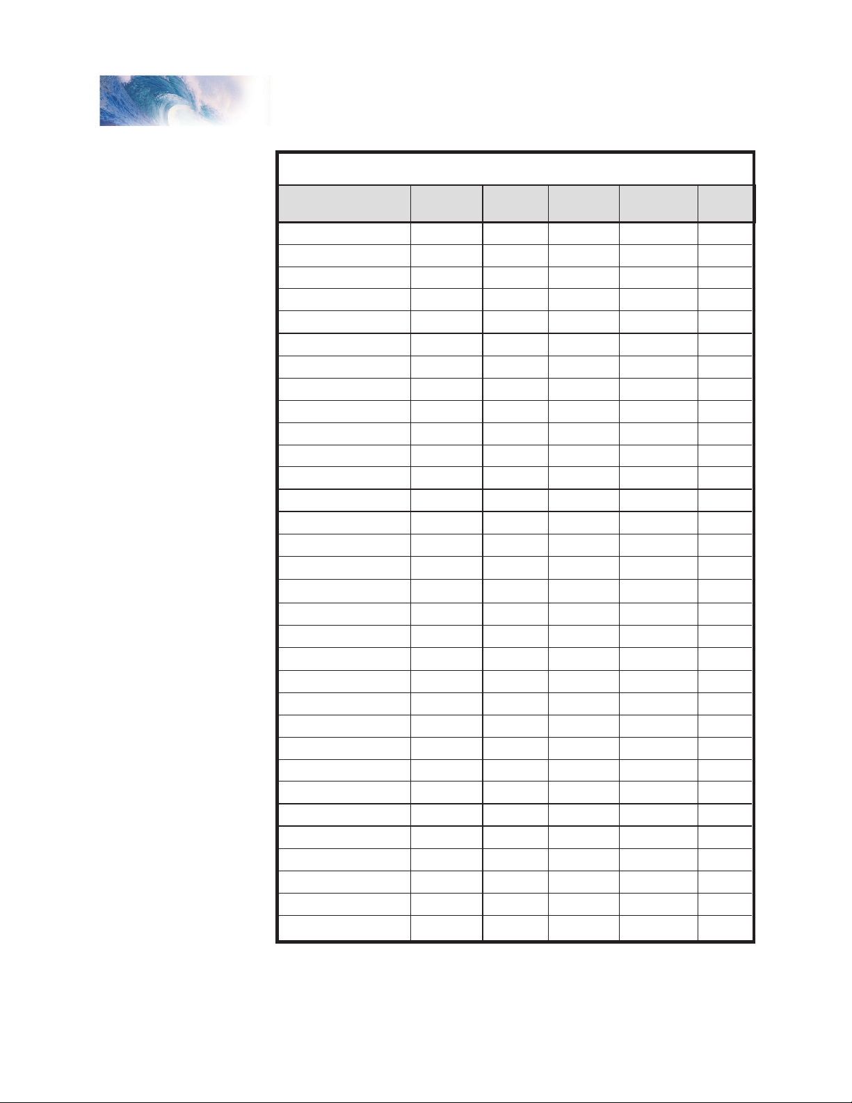
To assist the novice user, we have created Table A on the next page that lists
the correct value for CV 29 to get the desired operating modes.
To use the table, simply find the row that has the modes you want and
program CV 29 with the listed value.
The advanced user should refer to the Technical Reference for more details.
Remember, table values are in decimal. If your command station uses Hex
(Hexadecimal), you will need to convert the value shown using Appendix A.
- Sets the decoder to recognize its primary
Tsunami Steam Sound User’s Guide Page 15
Page 19
Basic Programming
Primary (CV1)
Primary (CV1)
Primary (CV1)
Primary (CV1)
Primary (CV1)
Primary (CV1)
Primary (CV1)
Primary (CV1)
Primary (CV1)
Primary (CV1)
Primary (CV1)
Primary (CV1)
Primary (CV1)
Primary (CV1)
Primary (CV1)
Primary (CV1)
Extended (CV17:18)
Extended (CV17:18)
Extended (CV17:18)
Extended (CV17:18)
Extended (CV17:18)
Extended (CV17:18)
Extended (CV17:18)
Extended (CV17:18)
Extended (CV17:18)
Extended (CV17:18)
Extended (CV17:18)
Extended (CV17:18)
Extended (CV17:18)
Extended (CV17:18)
Extended (CV17:18)
Extended (CV17:18)
Address Type
14
14
28/128
28/128
14
14
28/128
28/128
14
14
28/128
28/128
14
14
28/128
28/128
14
14
28/128
28/128
14
14
28/128
28/128
14
14
28/128
28/128
14
14
28/128
28/128
Speed
Steps
Normal
Reversed
Normal
Reversed
Normal
Reversed
Normal
Reversed
Normal
Reversed
Normal
Reversed
Normal
Reversed
Normal
Reversed
Normal
Reversed
Normal
Reversed
Normal
Reversed
Normal
Reversed
Normal
Reversed
Normal
Reversed
Normal
Reversed
Normal
Reversed
Locomotive
Direction
0
1
2
3
4
5
6
7
16
17
18
19
20
21
22
23
32
33
34
35
36
37
38
39
48
49
50
51
52
53
54
55
CV 29
Valu
e
Analog
Mode?
No
No
No
No
Ye
s
Ye
s
Ye
s
Ye
s
No
No
No
No
Ye
s
Ye
s
Ye
s
Ye
s
No
No
No
No
Ye
s
Ye
s
Ye
s
Ye
s
No
No
No
No
Ye
s
Yes
Ye
s
Ye
s
Use Speed
Ta
bles?
No
No
No
No
No
No
No
No
Ye
s
Ye
s
Ye
s
Yes
Ye
s
Ye
s
Ye
s
Ye
s
No
No
No
No
No
No
No
No
Ye
s
Ye
s
Ye
s
Yes
Ye
s
Ye
s
Ye
s
Ye
s
Table A. Quick-Reference Table for CV 29 Values
Tsunami Steam Sound User’s Guide Page 16
Page 20

Tsunami Steam Sound User’s Guide Page 17
Basic Programming
Step 3: Configuring the Throttle
There are seven CVs that characterize the Tsunami’s throttle response and
28 more used to create a custom speed table:
CV 2, VStart
CV 3, Acceleration Rate
CV 4, Braking Rate
CV 25, Speed Table Select
CV 29, Configuration Data
CV 66, Forward Trim
CV 95, Reverse Trim
CV 67-94, Loadable Speed Table
This may sound like a lot of CVs but don’t worry; it’s not necessary to change
all of them if you don’t want to. We’ve already talked about speed step
selection in CV 29 (Step 2).
Set the Start Voltage
Tsunami provides CV 2, Vstart, to set the starting voltage that is applied to
the motor at Speed Step 1 and is used to compensate for inefficiencies in
the locomotive’s motor and driveline. CV 2 may be programmed with any
value between 0 and 255 with each step in value being about 0.5% of the
maximum available motor voltage. To calculate the value of CV 2, you can
use the formula:
Desired Starting Voltage
CV 2 = 255 X ——————————————
Maximum Motor Voltage
If your DCC system supports Operations Mode Programming, an alternative
method for setting Vstart is to turn your throttle to the first speed step and
then use the operations mode programming feature to increase the value in
CV 2 until the locomotive just begins to move.
Set the Acceleration and Braking Rates
Tsunami provides two CVs to simulate the momentum due to train weight.
CV 3, Acceleration Rate, controls how fast the locomotive responds to
increases in throttle settings and CV 4, Braking Rate, controls how fast the
locomotive will respond to decreases in the throttle setting.
Both CVs can be programmed with any value between 0 and 255 with 255
corresponding to the slowest acceleration or braking rate. Lower settings
yield a more responsive locomotive, which is useful for switching. When both
CVs are set to 0, the locomotive will respond nearly instantly to any throttle
changes. A setting of 255, on the other hand, will require several minutes for
a locomotive to reach full speed from a standing stop!
Tsunami’s Dynamic Digital Exhaust feature will be more dramatic if you use
Tsunami Steam Sound User’s Guide Page 17
Page 21
Basic Programming
2
3
4
5
6
7
8
9
10
11
12
13
14
15
16
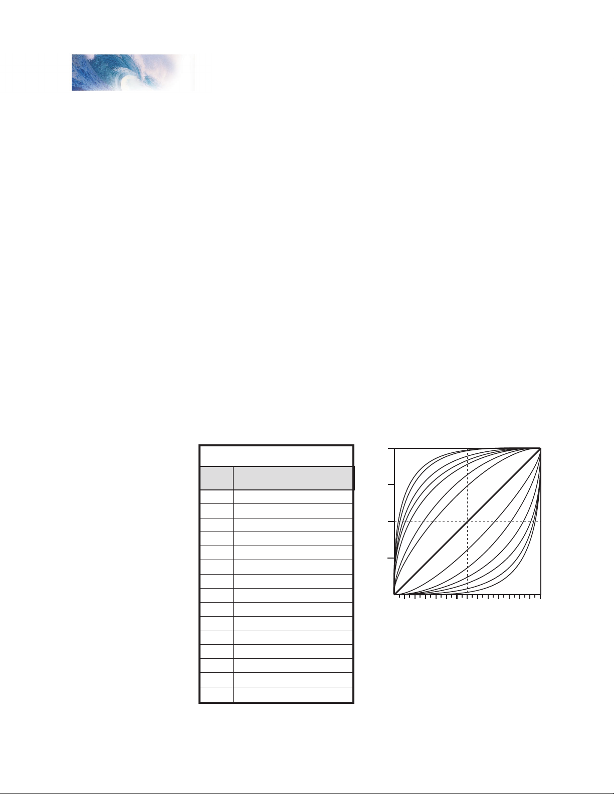
CV 25
Speed Curve Type
Straight LIne
Logarithmic Curve 1
Logarithmic Curve 2
Logarithmic Curve 3
Logarithmic Curve 4
Logarithmic Curve 5
Logarithmic Curve 6
Logarithmic Curve 7
Exponential Curve 1
Exponential Curve 2
Exponential Curve 3
Exponential Curve 4
Exponential Curve 5
Exponential Curve 6
User Loadable Speed Table
Table B. Speed Table Selection
100%
75%
50%
25%
0%
0 2 4 6 8 10 12 14 16 18 20 22 24 26 28
LOG
7
LOG
5
LOG
6
LOG
3
LOG
2
LOG
1
LOG
4
LINEAR
EXP
1
EXP
2
EXP 3
EXP
4
EXP
5
EXP
6
Speed Step
Motor Speed
larger values for these CVs; we therefore suggest setting CV 3 and CV 4 to a
minimum value of 16 or higher.
If you are using 14 or 28 Speed Step modes, setting CV 3 and CV 4 to any
value greater than 0 will also improve the Tsunami’s throttle response. While
it is accelerating or braking, Tsunami interpolates between speed steps so
in effect, your locomotive will respond as if it were being controlled with 128
speed steps. No more sudden lurching from one speed step to another!
Select the Speed Table
Tsunami provides 14 preset and one loadable speed table that can be used
for several purposes:
1. Matching the Auto Exhaust chuffing rate to locomotive speed.
2. Speed matching one locomotive to another.
3. Changing the feel of the throttle. For example, you could configure
a switching locomotive so there are more speed steps available at
lower speeds for switching and fewer steps at high speeds where the
locomotive is seldom operated.
4. Compensating for an improperly designed driveline so the locomotive will
operate within its prototypical speed range.
Tsunami Steam Sound User’s Guide Page 18
Preset Speed Tables
CV 25, Speed Table Select, is used to select which speed curve will be used
by the DSD. CV 25 may be programmed with any value between 2 and 15 to
select one of the preset speed curves shown in Table B, below.
Page 22

Tsunami Steam Sound User’s Guide Page 19
Basic Programming
67
68
69
70
71
72
73
74
75
76
77
78
79
80
81
82
83
84
85
86
87
88
89
90
91
92
93
94
CV#
4
7
11
14
18
22
25
39
32
36
39
43
46
50
54
57
61
64
67
71
75
78
82
86
89
93
96
100
% Full
Speed
9
18
27
36
45
55
64
73
82
91
100
109
118
127
137
146
155
164
173
182
191
200
209
219
228
237
246
255
CV
Value
Speed
Step
1
2
3
4
5
6
7
8
9
10
11
12
13
14
15
16
17
18
19
20
21
22
23
24
25
26
27
28
Table C. Calculating the
User Loadable Speed Table
The exact throttle response for each curve is shown graphically. The
logarithmic curve provides a rapid throttle response at low speeds, while the
exponential curve provides a rapid throttle response at higher speeds.
In order for the speed table selection in CV 25 to take effect, bit 4 of CV 29
must be set to 1. Refer to the previous section “Configuring the Decoder” or
the Technical Reference to determine the correct value for CV 29.
Set the User Loadable Speed Curve
The User Loadable Speed Table allows you to create virtually any throttle
response curve you can imagine. You will first need to design and program
the Loadable Speed Table. The Loadable Speed Table consists of 28 data
points contained in CVs 67 through
94, each defining the percentage
of motor voltage applied at a
given speed step. Each data point
can contain a value of 0 to 255
corresponding to 0 to 100% of
available motor voltage.
Tsunami Steam Sound User’s Guide Page 19
In 28 speed-step mode, each data
point directly corresponds to a speed
step. In 128 speed-step mode,
each data point corresponds to
every four and a half speed steps.
The motor voltage for intermediate
steps is interpolated by Tsunami
to produce a smooth curve. In 14
speed-step mode, alternate (odd
numbered) data points correspond
to speed steps 1-14. Important: all
28 data points must be programmed
even for 14 speed-step mode or an
unpredictable throttle response may
occur while accelerating or braking.
To create a speed curve, begin
by assuming that Tsunami will be
operated in 28-speed step mode.
Don’t worry if you are using another
mode - Tsunami will automatically
take care of the translation between
modes.
1. Start by making a table
containing 28 entries - one entry
for each speed step.
2. For each entry, record the
desired throttle response as a
percentage of full speed, i.e., 0
to 100%.
Page 23

Basic Programming
3. Compute and record the CV value for each step using the following
formula:
Percentage of Full Speed (from Step 2)
CV Value = 255 X ———————————————————
100
4. Program CV 67 with the value computed in step 3 for the first data entry
(Speed Step 1).
5. Program CV 68 with the value computed in step 3 for the second data
entry (Speed Step 2).
6. Repeat step 5 for each of the remaining 26 CVs from CV 69 to CV 94
until they have been programmed with their respective values.
7. Set CV 25 to 16 to select the user loadable speed table.
8. Set bit 4 of CV 29 to 1 to enable speed table use. Refer back to the
previous section “Configuring the Decoder” to determine the correct
value for CV 29.
Table C may be followed as an example and lists the CV values for a straightline response.
Adjust the Forward and Reverse Trim
Tsunami provides two CVs for adjusting or ‘trimming’ the forward and reverse
speeds.
CV 66, Forward Trim
CV 95, Reverse Trim
These CVs multiply all data points in the speed tables by a factor of n/128 (n
is the CV value) allowing the overall speed curve to be adjusted up or down
without reloading all 28 data points again. These CVs will not have any effect
when the speed tables are disabled (i.e., CV 29, bit 4 = 0)
These CVs may contain any value between 0 and 255. Trim values between
129 and 255 will increase speed curve values between 100% and 200% in
approximately 1% steps. Trim values between 1 and 127 will decrease speed
curve values between 1% and 99%. A value of 128 yields a scaling factor of
1.0 and has no effect on the speed curve.
Using different values for the forward and reverse trim will yield different
forward and reverse speeds.
Tsunami Steam Sound User’s Guide Page 20
Page 24

Tsunami Steam Sound User’s Guide Page 21
Basic Programming
Step 4: Configuring for Consist Operation
The DSD supports advanced consist operations, which use five related CVs:
CV 19, Consist Address
CV 21, Consist Function Control 1
CV 22, Consist Function Control 2
CV 23, Consist Acceleration Rate
CV 24, Consist Braking Rate
Consists Explained
A consist is a group of locomotives that are set up to respond to throttle
commands as a single unit. Consists make it easy for one operator to run a
double headed steam train or a multi-unit diesel lash-up for example. The
consist CVs allow the DSD to recognize a new address assigned to the
consist without changing its primary or extended addresses. Additionally,
they allow each locomotive in the consist to be run as a single unit but with
different function properties allowing for example, only the horn to blow on
the lead engine.
Consist Address
Each locomotive in the consist is assigned the same consist address by
programming CV 19 with the consist address between 1 and 127. If a
locomotive is facing backwards in the consist (common in diesel operations),
it should be programmed with the same consist address plus 128. If the
forward facing locomotives are set to consist address 60 for example, the
backwards engine must be set to 60+128 = 188. Failure to do this will turn
the consist into an angry pushme-pullyou as all locomotives will try to move
forward from the perspective of their own cab and a few pulled couplers
might result!
To deactivate the consist address and restore normal operation, CV 19 must
be reprogrammed to 0.
Note that when the consist address is set, the DSD will continue to respond
to instructions sent to its primary or extended address except for speed and
direction data.
The DSD will not respond to operations mode programming commands
sent to its consist address. These commands must always be used with the
primary or extended address.
Consist Function Enable
CV 21 and 22 allow you to define how each engine individually responds
to function commands sent to the consist address. When the consist is
enabled, CV 21 controls which of functions 1-8 are active and CV 22 controls
the F0 function for forward (F0(f)) and reverse (F0(r)), as well as functions
9-12.
Tsunami Steam Sound User’s Guide Page 21
Page 25

Basic Programming
1 2
F0(f) F0(r)
22
CV#
F12
4
F11
8
F10
16
F9
32
Table E. Consist Function Control 2
F8
21
CV#
F11F22F3
4
F48F5
16
F6
32
Table D. Consist Function Control 1
F7
64 128
Direction
CV 19 (Consist Address)
CV 21
CV 22
Engine Address
Nor
mal
40
128
18
5239
4088
Normal
40
135
17
Lead Unit Trailing Unit
CV 21 and 22 take effect only when the consist address is set. When
function commands are used with the DSD’s primary or extended address, all
functions will continue to work regardless of the settings of CV 21 and 22.
Use Table D to calculate the correct value for CV 21, and Table E to calculate
the correct value for CV 22. Begin by looking at Table D and determining
which functions you want active in the consist and circle the number below it.
When you are done, add up all the circled numbers in the row and program
the total into CV 21.
Now look at Table E and do the same: add up all the circled numbers in the
row and program CV 22 with the sum.
Tsunami Steam Sound User’s Guide Page 22
Note that each DSD in the consist will require a different set of values for CV
21 and 22 depending upon your requirements.
Consist Example:
Consider a double-header consisting of two engines, #4088 and #5239. Let’s
suppose we wish to operate these two engines as a single unit with consist
address 40.
You might want the brake squeal (F11) and audio mute (F8) functions to work
on both engines. However, you will likely want the headlight (F0(f)), whistle
(F2) short whistle (F3) and bell (F1) to only work on the lead engine, #4088,
and the backup light (F0 (r)) to work only on #5239.
Page 26

Tsunami Steam Sound User’s Guide Page 23
Basic Programming
Engine 4088.
This is the lead engine. Program CV 19 to 40, the new consist address.
Using Table D, program CV 21 with the sum of the value corresponding to
F1, F2, F3 and F8:
CV 21 = 1 + 2 + 4 + 128 = 135
Then using Table E, determine the value for CV 22 by summing the values
for F0(f) and F11:
CV 22 = 1 + 16 = 17
Engine 5239.
Program CV 19 with the new consist address, 40. As this engine will only
have the reverse light, mute, and brake squeal functions active, different
values are required for CV 21 and 22. Using Table D, program CV 21 with the
value corresponding to F8:
CV 21 = 128
Then using Table E, determine the value for CV 22 by summing the values
for F0(r) and F11:
CV 22 = 2 + 16 = 18
Consist Inertia Control
CVs 23 and 24 can be used to increase or decrease the locomotive’s
acceleration and braking response whenever it is part of a consist (i.e., CV 19
is programmed with a valid address).
CV 23 controls the consist acceleration rate and CV 24 controls the consist
braking rate. When the consist address is active a new acceleration rate
is calculated by adding the value in CV 23 to the baseline acceleration rate
in CV 3. Similarly, a new braking rate is calculated by adding CV 24 to the
baseline braking rate in CV 4. When the consist address is set to 0, CV 23
and 24 have no effect.
Both CV 23 and 24 may be set to any value between -127 and +127. A
positive value will produce a slower throttle response while a negative value
will result in a quicker throttle response.
If the sum of consist and baseline rate exceeds 255, then the final rate is
set to the maximum value of 255. If the sum of consist and baseline rate is
negative, then the final rate is set to the minimum value of 0.
To set a positive value, simply program the CV with the desired number
between 0 and 127. To set a negative value, first change the sign of the value
back to positive and then add 128. Thus, to set -5, program the CV with 5 +
128 = 133. Note that a setting of 128 is the same as 0 and has no effect.
Tsunami Steam Sound User’s Guide Page 23
Page 27

Basic Programming
33
34
35
36
37
38
39
40
41
42
43
44
45
46
128
128
128
128
16
16
16
16
2
2
2
1
1
1
64
64
64
64
8
8
8
8
1
1
1
32
32
32
32
4
4
4
4
X
16
16
16
16
2
2
2
2
X
8
8
8
8
1
1
1
1
X
4
4
4
4
2
2
2
2
1
1
1
1
32
32
32
32
4
4
4
2
2
2
64
64
64
64
8
8
8
4
4
4
128
128
128
128
16
16
16
8
8
8
X
X
X
32
32
32
16
16
16
64
64
64
32
32
32
128
128
128
64
64
64
128
128
128
Control CV
F0 (f)
F0 (r)
F1
F2
F3
F4
F5
F6
F7
F8
F9
F10
F11
F12
Function Key
HL
BL
WH
BEL
SHW
STM
WS
FX5
DY
N
FX6
Table F. Function Mapping Table
DIM
MUT
INJ
BRK
CPL
Bold Numbers indicate default settings.
Step 5: Function Mapping
Function Mapping Explained
Function mapping allows the DSD to be reconfigured so that sound effects
and function outputs can respond to a different function key input. This is
especially useful for users who have throttles with less than thirteen function
keys as now they can pick and choose what effects they can control instead
of being restricted to an arbitrary assignment.
There are 14 function mapping CVs - twelve CVs, 35-46 are used to assign
output control to function keys 1 through 12 respectively.
The other two CVs, 33 and 34 are both for the F0 function. CV 33 controls
which outputs are on when F0 is on and the locomotive is moving forward.
CV 34 controls which outputs are on when F0 is on and the locomotive is
moving in reverse. If the same output is selected in both CV 33 and CV 34,
that function will turn on when the F0 function is on regardless of locomotive
direction.
Not all keys can control all outputs or effects. The table below shows which
functions can be mapped to which outputs. Note that a function key can be
set up to control more than one output.
Tsunami Steam Sound User’s Guide Page 24
Page 28

Tsunami Steam Sound User’s Guide Page 25
Basic Programming
An output can be also be controlled by more than one function key. In the
second case, if an output is mapped to two function keys, either key will turn
that output on, however, the output will not turn off until both function keys
have been turned off.
To determine the correct CV value,
1. Find the column in the Function-Mapping Table corresponding to the
function or sound effect output you wish to control.
2. Next locate the row corresponding to the function key you wish to use for
controlling the selected output.
3. Note the number located in the box at the intersection of the row and
column you have selected.
4. Program the CV listed in the row chosen in step 2 with the value found in
step 3.
Example 1, Swapping the Bell and Short Whistle functions:
Some DCC systems label Function 3 on their cab as the Bell control.
However, Tsunami’s default Bell control is Function 1. Fortunately, we can
use function mapping to re-assign the controls so that the label on the cab
matches the utility in the decoder. Since F3 controls the Short Whistle, we will
simply swap it with F1 as follows:
Using Table F, we first re-assign Function 3 to the Bell. First, find the column
corresponding to the Bell. Then find the row for Function 3. Note the value,
1, found in the box intersected by the row and column. Finally, program this
value into the CV controlling Function 3, in this case CV 37.
Next, re-assign Function 1 to the Short Whistle following the same procedure.
Locate the column corresponding to the Short Whistle. Then find the row for
Function 1. Note the value, 128, found in the box intersected by the row and
column and program this value into CV 35, the CV controlling Function 1.
Example 2, Independent Dynamo Control:
As shipped from the factory, Function 0 controls both the Headlight (or
Backup Light when in reverse) and the Dynamo sound together. Let’s
suppose you desire to use another function to control the Dynamo sound so
it can be turned on or off without affecting the headlight. This would be simple
enough were it not for the fact that all the other function keys are already in
use. The solution then, is to decommission another function so it may be reassigned to the dynamo.
Looking over Table F, we see that any of Function F0 thru F9 may be
remapped to include the Dynamo function. Functions 10-12 are not
candidates since the boxes for these functions are blacked out under the
Dynamo column. However, we could logically assign Function 5 to control
both the FX5 and FX6 lights, which frees up Function 6 to control the
Dynamo.
But first, we need to reprogram the mapping for F0 so that the Dynamo is
no longer controlled with this function. Remembering that F0 uses two CVs,
(CV 33 for forward and CV 34 for reverse), we program CV 33 to 1 so that F0
Tsunami Steam Sound User’s Guide Page 25
Page 29

Basic Programming
turns on the headlight in the forward direction. Then we program CV 34 to 2
so F0 turns on the Backup light in the reverse direction.
Next, setup Function 5 to control both FX5 and FX6. Using Table F, find the
columns corresponding to FX5 and FX6. Then find the row for Function 5.
Note the first value, 2, found in the box intersected by the F5 row and FX5
column. Then find the second value, 4, found in the box intersected by the F5
row and FX6 column. Add these two values together (2 + 4 = 6) and program
the sum into CV 39, the CV controlling Function 5.
Finally, we set CV 40 to 8 so F6 turns the Dynamo on and off.
To summarize, program:
CV 33 = 1 (sets F0(f) to headlight)
CV 34 = 2 (sets F0(r) to backup light)
CV 39 = 6 (sets F5 to FX5 and FX6)
CV 40 = 8 (sets F6 to Dynamo)
Remember, if the lighting functions are still set to the Dyno-Light effect, both
the F0 and F6 functions must now be turned on for the lights to illuminate!
Working with 8-Function Cabs
While Tsunami can support 12 function keys, many cabs are limited to only
8 or 9 functions and you may feel as though you will lose some ability to
enjoy your new Tsunami Digital Sound Decoder. Most of the time, some
clever function mapping will allow you to access and use all of the available
features.
Instant Function Swapping
By setting CV 30 to 4, the function assignments for F5-F8 are instantly
swapped with the function assignments for F9-F12. Think of CV 30 as sort of
a ‘shift’ key so that when it is set to 4,
F5 = Water Stop F9 = FX5
F6 = Injector F10 = FX6
F7 = Brake Release/Squeal F11 = Dimmer
F8 = Coupler F12 = Mute
And when it is set back to 0,
F5 = FX5 F9 = Water Stop
F6 = FX6 F10 = Injector
F7 = Dimmer F11 = Brake Release/Squeal
F8 = Mute F12 = Coupler
If you do not need the mute, dimmer or extra lighting functions, you can set
CV 30 to 4 and simply be done with it. Otherwise, programming CV 30 back
and forth between 0 and 4 is a little inconvenient and a more sophisticated
solution is needed.
Tsunami Steam Sound User’s Guide Page 26
Page 30

Tsunami Steam Sound User’s Guide Page 27
Basic Programming
A Better Method
In order to more fully utilize the Tsunami with an 8 Function cab, it is
necessary to free up some function keys by doubling up on some functions
and/or turning other functions over to automatic control.
We begin by noting which sound functions may be relegated to automatic
control (see page 62 for details):
Short Whistle (F3)
Steam Release (F4)
Brake Squeal (F11)
The Injector sound (F10) may also be automatically triggered by Fireman
Fred (see page 48).
The Mute function (F8) may be automatically set by way of the Quiet Mode
(page 48).
Next, we look to see which outputs could be combined so that they are
controlled with a single function. There aren’t too many of these but it might
be reasonable to decide to use F0 to turn on all lighting outputs including
FX5 and FX6 as well as the Dynamo sound. Or you could use one function to
control both FX5 and FX6 as was done in Example 2.
Finally, we could decide that some functions aren’t needed and simply
discard them.
We now have seven or so functions that can be juggled about. Since we
need to make room for only four, this provides us some flexibility to pick and
choose to best meet our requirements.
Example 3:
In this example, we will let Fireman Fred run the injectors so we no longer
need F10. We’ll also set up the Short Whistle for automatic signaling so F3 is
now available. Let’s presume that FX5 will be used for number board lights
and FX6 for a cab light. We can gang up FX5 and FX6 with Function 0 so
that these lights are on whenever the headlight or backup light is on freeing
up functions F5 and F6.
Using Table F, we can proceed to re-map functions as follows. Starting with
F0, configure the forward direction to control the Headlight, FX5, FX6 and
Dynamo:
Set CV 33 = 1 + 16 + 32 + 64 = 113
For the reverse direction, set F0 to control the Backup light, FX5, FX6 and
Dynamo:
Set CV 34 = 2 + 16 + 32 + 64 = 114
Tsunami Steam Sound User’s Guide Page 27
Page 31

Basic Programming
Then configure F3 to control the Water Stop Sound:
Set CV 37 = 64
Next, we configure F5 and F6 to control the Brake Squeal and Coupler
respectively. But wait! Looking at Table F, it appears that this can’t be done.
The trick is to use the Instant Function Swapping feature so Function 5 now
controls the output assigned to Function 9, Function 6 now controls the
output of Function 10, and so forth.
To activate Function Swapping, set CV 30 to 4. Once this is done, the control
CVs for a particular function also get swapped so that the function mapping
CVs are assigned as follows:
Function 5 is now mapped with CV 43
Function 6 is now mapped with CV 44
Function 7 is now mapped with CV 45
Function 8 is now mapped with CV 46
Function 9 is now mapped with CV 39
Function 10 is now mapped with CV 40
Function 11 is now mapped with CV 41
Function 12 is now mapped with CV 42
Now use Table F to remap F5 to control the Brake Squeal:
Set CV 43 = 128
Then map F6 to control the coupler:
Set CV 44 = 128
We would like to keep the original function assignments for F7 (dimmer)
and F8 (mute). By turning on the Function Swapping feature, however, the
outputs for these functions are now mapped through CV 45 and 46 which,
by default, are set to control some other output. It is necessary to reprogram
these CVs as well to get the desired functionality:
Re-map F7 to control the dimmer:
Set CV 45 = 8
Re-map F8 to control the mute:
Set CV 45 = 16
Finally, we must activate the automatic whistle signals by setting CV 198 to 2.
The injectors are already part of Fireman Fred’s repertoire so there is nothing
else needing change.
Tsunami Steam Sound User’s Guide Page 28
Page 32

Tsunami Steam Sound User’s Guide Page 29
Basic Programming
Working with 4 Function Cabs
With a 4-function cab (actually in most cases, five functions - F0 plus F1-F4),
you will have to give something up! By using Tsunami’s automatic sound
controls, hopefully it doesn’t need to be much.
Example 4:
In this example, we will use automatic control for the Short Whistle, Mute,
Injector, Brake Squeal, and Steam Release. FX5 and FX6 will be ganged up
with F0 as was done for the 8-Function Cab example. F1 and F2 will continue
to be used for the Bell and Whistle.
This frees up F3, which we can assign to the water stop, and F4, which we
can use to control the dimmer. The only effect we must completely give up
under this scenario is the coupler sound since it only maps to F10 -F12 (or
F6-F8 with Function Swapping turned on). Sorry.
Using Table F, we can proceed to re-map functions as follows. Starting with
F0, configure the forward direction to control the Headlight, FX5, FX6 and
Dynamo:
Set CV 33 = 1 + 16 + 32 + 64 = 113
For the reverse direction, set F0 to control the Backup light, FX5, FX6 and
Dynamo:
Set CV 34 = 2 + 16 + 32 + 64 = 114
Then configure F3 to control the Water Stop Sound:
Set CV 37 = 64
Set F4 to control the dimmer function:
Set CV 38 = 128.
To activate the automatic whistle signal, brake squeal and steam release,
program CV 198 to 26. To activate auto-mute, program CV 113 to 120 which
will shut the sounds off after 30 seconds once the train is brought to a stop
and all the functions are turned off (See page 48).
You can see that function mapping allows you a great degree of flexibility
to solve a variety of problems even if your cab is limited to less than 14
functions.
Tsunami Steam Sound User’s Guide Page 29
Page 33

Basic Programming
Bit 7 Bit 0
LED R17 XING PHSE HYPERLIGHT SELECTION
Step 6: Configuring the Lighting Outputs
Tsunami has four function outputs used for controlling the locomotive lights.
Each can be set for a variety of effects or as simple on/off lights. In addition,
you can use the Grade Crossing Logic to automatically activate the selected
lighting effect when you blow the whistle.
Tsunami provides six CVs for customizing the lighting effects:
CV 49, Headlight Configuration
CV 50, Backup Light Configuration
CV 51, FX5 Light Configuration
CV 52, FX6 Light Configuration
CV 59, Lighting Effect Flash Rate
CV 60, Grade Crossing Effect Hold Time.
Setting the Hyperlight Effects
Each lighting output has a corresponding CV that determines its operating
characteristics:
Hyperlight Select - Each output can be programmed to one of several
Hyperlight™ Lighting Effects as listed in Table G. Most effects are selfdescriptive and primarily warning beacons used for diesel locomotives. Some
effects, such as the Mars Light, were used in some steam engines as well.
Dimmable Headlight - The function output is normally an on/off output.
If the output is on, the output level will be reduced about 60% whenever
the dimmer function is on.
Mars Light - This effect simulates the sweeping figure-8 pattern of this
popular warning beacon.
Pyle National Gyralite - The Gyralite is similar to the Mars Light, but
generates a slow, wide, oval headlight sweep pattern.
Dual Oscillating Headlights - Similar in appearance to the common twinsealed-beam headlight, the oscillating headlight uses a moving reflector
to sweep the headlight beam in a tight circular motion.
Single and Dual Strobes - The Strobe effects simulate the white-hot burst
of light associated with the Xenon Strobe.
Tsunami Steam Sound User’s Guide Page 30
Page 34

Tsunami Steam Sound User’s Guide Page 31
Basic Programming
Western-Cullen D312 Rotary Beacon - This effect provides a spectacular
rendition of the revolving reflector and bulb assembly of the prototype
warning beacon found atop many diesels of the 60’s and 70’s.
Prime Stratolite - The Stratolite was a newer version of the rotary
beacon, with the prototype consisting of a revolving reflector with four
individual lamps arranged in a circular pattern which are electronically
flashed in a clockwise sequence. The Stratolite flashes in a rather
mechanical ‘stepped’ fashion, as opposed to the smooth motion of the
Rotary Beacon.
Type I and Type II Ditch Lights - These are identical when operating.
However, if the grade crossing logic is enabled, the Type I ditch light will
revert to a steady on state when it is not flashing whereas the Type II
lights will turn off.
Exhaust Flicker - This effect produces a random flicker whose intensity
increases with locomotive speed. This effect is best used by placing a
red/orange LED in the firebox or in the smokestack. As the locomotive
increases speed, it will glow brighter, imitating an increase in sparks and
exhaust gases.
Firebox Flicker - This effect produces a random flicker whose intensity
resembles a burning fire and can be used with a lamp placed in the
firebox area. The effect is improved when two lights are used, one yellow
and one red or orange and each connected to a separate function output.
Smart Firebox Flicker - This effect produces a random flicker whose
intensity is synchronized with the sound of Fireman Fred shoveling
coal. Whenever Fred ‘opens’ the firebox door and begins shoveling, the
lighting effect increases in brightness and then returns to a subdued level
when the firebox doors are ‘closed’.
Dyno-Light - This effect for steam locomotives synchronizes the lamp
brightness to the “output” of the dynamo such that the lamp brightness
gradually increases as the dynamo builds up speed.
Phase Select - Alters the timing of the effect so that it is 180 degrees out of
phase with the other effects. This allows you to have two light effects that
blink back and forth if desired. Set one effect to phase A and the other to
phase B.
Grade Crossing Logic - Causes the lighting effect to become active only
when the whistle has been sounded (and the corresponding lighting function
key is also on). A typical use would be to cause the ditch lights to flash at
a grade crossing. The grade crossing logic can be used with almost all
the Hyperlight effects. The on/off, dimmable headlight, Dyno-Light, FRED,
exhaust flicker, and firebox flicker effects will not be affected. The other
effects will either turn off (strobes and beacons) or revert to a steady on state
(mars light, ditch lights, etc.) as appropriate to prototype practice.
Tsunami Steam Sound User’s Guide Page 31
Page 35

Basic Programming
Rule 17 Headlight Operation - Converts the headlight and backup light
to independent, non-directional functions. When enabled, the headlight is
controlled as if it were FX5, Function 5 and the backup light as FX6,
Function 6.
LED Compensation Mode - Tsunami’s lighting effects can be used with
either incandescent bulbs or LEDs. However, because of their differences in
brightness characteristics, some lighting effects will appear less life-like when
initially set up with an LED. To correct this, Tsunami’s LED compensation
mode should be enabled which will improve the contrast of the lighting effect
by automatically adjusting the function output level to correct for the different
brightness characteristics of an LED.
To set the Hyperlight configuration CVs, proceed as follows:
1. First find the CV value in Table G on the next page for the desired
lighting effect and operating mode.
2. If you wish to enable Rule 17 Mode, add 64 to the table value shown,
otherwise, proceed to Step 3.
3. If you’re using incandescent bulbs, skip to Step 4. If you are using
LEDs, enable the LED Compensation Mode by adding 128 to the sum
computed in Step 2.
4. Program the sum computed in Step 3 into the CV corresponding to the
appropriate function output. Use CV 49 to set the headlight, CV 50 for
the backup light, CV 51 for Function 5 and CV 52 for Function 6.
Setting the Flash Rate and Hold Time
CV 59 is used to adjust the flash rate of the Hyperlight effect and has a range
of 0-15 with 15 being the slowest flash rate. When the Grade Crossing Logic
feature is enabled, CV 60 is used to adjust the length of time (in seconds)
an effect will remain active after the whistle key is released. CV 60 can be
programmed with any value between 0 and 15.
Example 1, Mars Light with Grade Crossing Logic
In this example, we will configure the headlight output for use with an
incandescent bulb as a Mars Light with Grade Crossing Logic enabled.
Following the steps outlined above, we proceed as follows:
1. We first look up the initial CV value in Table G for a Mars Light under the
column labeled ‘Crossing Logic On’ and find it is 34 for Phase A and 50
for Phase B. Since we are only setting up one light, we do not care about
the Phase and choose to the value for Phase A, 34.
2. Since we are not using Rule 17, we skip to Step 3.
3. Since we are not using LEDs, we skip to Step 4.
4. CV 49 (Headlight Configuration) is programmed with the value found in
Step 1 or 34.
Lastly, we need to set the grade crossing hold time to about six seconds by
programming CV 60 to 6.
Tsunami Steam Sound User’s Guide Page 32
Page 36

Tsunami Steam Sound User’s Guide Page 33
On-off
Dimmable
Mars Light
Gyralite
Oscillating Headlight
Single Flash Strobe
Double Flash Strobe
D312 Rotary Beacon
Prime Stratolite
Type I Ditch Light
Type II Ditch Light
FRED
Exhaust Flicker
Firebox Flicker
Smart Firebox Flicker
Dyno-Light
Effect Type
Phase A Phase B
CV Value
Crossing Logic Off Crossing Logic On
Phase A Phase B
0
1
2
3
4
5
6
7
8
9
10
11
12
13
14
15
16
17
18
19
20
21
22
23
24
25
26
27
28
29
30
31
32
33
34
35
36
37
38
39
40
41
42
43
44
45
46
47
48
49
50
51
52
53
54
55
56
57
58
59
60
61
62
63
Table G. Hyperlight Control Mode Settings
Basic Programming
Example 2, LED Firebox Flicker
In this example, we will configure the FX5 and FX6 outputs for a firebox
flicker effect using LEDs.
1. We first look up the initial CV value in Table G for a Firebox Flicker under
the column labeled ‘Crossing Logic Off’ and find it is 13 for Phase A and
29 for Phase B. Since we are setting up two lights, the overall effect will
be enhanced if one LED flickers differently from the other. So for FX5 we
use the Phase A value, 13, and for FX6 we use the Phase B value, 29.
2. Since we are not using Rule 17, we skip to Step 3.
3. Since we are using LEDs, we add 128 to the values found in Step 1 and
get: FX5 = 13 + 128 = 141
FX6 = 29 + 128 = 157
4. CV 51 (FX5 configuration) is programmed with the value found in Step 3
or 141. CV 52 (FX6 configuration) is likewise programmed with 157.
Tsunami Steam Sound User’s Guide Page 33
Page 37

Basic Programming
Example 3, Alternating Ditch Lights with Crossing Logic
In this example, we will configure the FX5 and FX6 outputs for use with bulbs
as Type I Ditch lights that flash when the whistle is blown (our steam loco is
being operated on a modern day railroad as a restored excursion train!).
1. We first look up the initial CV value in Table G for a Type I Ditch Light
under the column labeled ‘Crossing Logic On’ and find it is 42 for Phase
A and 58 for Phase B. To get the lights to flash back and forth, FX5 is set
to the Phase A value and FX6 is set to the Phase B value.
2. Since we are not using Rule 17, we skip to Step 3.
3. Since we are using bulbs rather than LEDs, we skip to Step 4.
4. CV 51 (FX5 configuration) is programmed with the value found in step A
or 42. CV 52 (FX6 configuration) is likewise programmed with 58.
Lastly, we need to set the grade crossing hold time to about five seconds by
programming CV 60 to 5. Initially, the FX5 and FX6 lights should be steady
on (Note: use Function 5 and 6 to turn FX5 and FX6 on first!). When the
whistle is sounded, the two lights will flash back and forth. The lights will
revert back to a steady on state after about five seconds following the release
of the whistle key.
Tsunami Steam Sound User’s Guide Page 34
Page 38

Tsunami Steam Sound User’s Guide Page 35
Sound Programming
Step 7: Modifying the Sound Effects
One of the great things about Tsunami Digital Sound Decoders is the ability
to adjust the various sound effects to suit your ear and respond in the manner
that you prefer.
Audio Mixer Controls
The Tsunami sound decoder provides up to 25 independent controls for
setting the volume levels of each sound effect much like that of a modern
sound studio mixing board. To set the sound level for a particular effect,
set the corresponding CV to any value between 0 (zero volume) and 255
(maximum volume).
For the best sound quality, you will want to run the mixer as “hot” as possible
(audio jargon for maximizing the volume level). First determine which sound
you want to be the loudest (usually the whistle) and set its volume level to
around 225. Then adjust all the other sound levels relative to the whistle
volume. Finally, use the Master Volume Control, CV 128, to set the overall
volume of the decoder to the desired level.
A certain level of prudence is needed when adjusting the mixer levels to
avoid a condition known as ‘clipping’ or ‘limiting’ which occurs when the sum
of two or more signals exceeds the capacity of the output channel. As its
name implies, clipping results in the lopping off of the sound signal peaks and
manifests itself as distortion accompanied with a level of clicking or popping
sounds.
To avoid a clipping condition, consider which sounds are likely to be played
at the same time and take care to ensure that their corresponding mixer
levels are not set too high. For example, the whistle and exhaust chuff are
usually heard together and you will likely want both to be as loud as possible.
Rather than simply crank both sounds up to the maximum level, start with
one mixer channel near, but not quite at maximum (this provides a little extra
‘headroom’) and then gradually bring up the second mixer channel setting to
the desired level. If you start to hear some distortion, simply back down one
mixer channel or the other until the distortion goes away.
Your Tsunami sound decoder has a 96dB dynamic range which is plenty for
most audio work and as long as you keep the sound levels balanced in a
prototypical fashion, you should have no problems.
Note that the Primary Mixer CVs are real time controls, meaning that any
changes to their settings will be immediately reflected in the sound level. On
the other hand, the Secondary Mixer levels are not real time. If you change
their setting while the respective sound effect is playing, you will not hear a
change in volume until the sound is turned off and started again.
Tsunami Steam Sound User’s Guide Page 35
Page 39

Sound Programming
CV 128, Master Volume Control
Primary Audio Mixer CVs
CV 129, Whistle mixer level
CV 130, Bell mixer level
CV 131, Exhaust mixer level
CV 132, Airpump mixer level
CV 133, Dynamo mixer level
CV 134, Blower mixer level
CV 135, Rod clank mixer level
CV 136, Steam hiss mixer level
Secondary Mixer CVs:
CV 137, Coupler Clank mixer level
CV 138, reserved
CV 139, Brake squeal mixer level
CV 140, Brake release mixer level
CV 141, Snifter valve mixer level
CV 142, Johnson Bar/Power reverse mixer level
CV 143, Pop Valve mixer level
CV 144, reserved
CV 145, Blower draft mixer level
CV 146, Water stop mixer level
CV 147, Injector mixer level
CV 148, Coal Shoveling mixer level
CV 149, Wrenches mixer level
CV 150, Oilcan mixer level
CV 151, Grease gun mixer level
CV 152, reserved
are as follows:
Using the Tsunami Equalizer
Tsunami’s built-in equalizer (or “EQ” as the audio guys like to call it) is
much like that you’d on your home stereo system. The equalizer allows you
to selectively cut and boost sound levels by +/-12dB over seven selected
frequency ranges and provides the “ultimate” tone control.
When most people hear about Tsunami’s equalizer, their first reaction is
“Great, now I can really crank up the bass!” What they don’t realize is that the
equalizer is also there to cut out the low frequencies as well.
Every speaker has a limit to the lowest frequency it can efficiently reproduce.
This is determined by a number of factors and in particular, the speaker’s
physical size. To reproduce a low frequency sound at high volume requires
the ability to move a lot of air, and hence a large diameter diaphragm.
On the other hand, the electromagnet at the base of the speaker cone will
react just fine to even the deepest bass. So if we try to drive a low frequency
sound signal thru a small speaker, the speaker still physically reacts to the
signal - we just don’t hear it very well because only a small amount of air is
Tsunami Steam Sound User’s Guide Page 36
Page 40

Tsunami Steam Sound User’s Guide Page 37
Sound Programming
62Hz
0 dB
128
-12 dB
0
-6 dB
60
-3 dB
96
+6 dB
192
-12 dB
0
+6 dB
192
CV 154
Flat
Micro Speaker < 1” Diameter
Small Speaker 1-2” Diameter
Medium Speaker 3-4” Diameter
Large Speaker >4” Diameter
Edgeport Speaker
Micro Speaker < 1” Diameter
User Customizable
0
1
2
3
4
5
6
7
0 dB
128
-12 dB
0
-3 dB
96
+4.1 dB
168
+3 dB
160
-12 dB
0
+3 dB
160
CV 155
0 dB
128
+7.12 dB
200
+4.1 dB
168
+2.3 dB
148
+1.5 dB
140
0 dB
128
+1.2 dB
136
CV 156
0 dB
128
+3 dB
160
+3 dB
160
+1.1 dB
136
0 dB
128
-3 dB
96
0 dB
128
CV 157
0 dB
128
+1.5 dB
140
0 dB
128
0 dB
128
0 dB
128
-3 dB
96
+1.2 dB
136
CV 158
0 dB
128
+0.8 dB
132
0 dB
128
0 dB
128
0 dB
128
-5.2 dB
68
+3 dB
160
CV 159
0 dB
128
0 dB
128
+0.8 dB
132
+6 dB
128
0 dB
128
-3.8 dB
84
+6 dB
192
CV 160
125Hz 250Hz 500Hz 1Hz 2Hz 4HzPreset No. Description
Table H. Equalizer Presets
(Numbers in Red indicate equivalent CV Value)
being pushed about. If we turn up the volume, things will not likely improve
much and what’s worse, the speaker cone will eventually be pushed against
its physical travel limits resulting in annoying clicking and popping sounds.
This is where the equalizer’s ability to “cut” frequencies out becomes
important. By removing the inaudible low frequency sound components, the
speaker is now able to work more efficiently (i.e. louder) in the audio range it
was designed for.
EQ Presets
Using the equalizer begins with CV 153, the EQ Control Register. This CV
may be programmed with any value between 0 and 7. A setting of 0 disables
the EQ as if it were never there. Settings 1 thru 6 select a factory preset
which tailors the frequency response to several of SoundTraxx’s more
popular on-board speakers. The table below shows the presets and their
equivalent settings which may be used as the basis for developing your own
settings.
Tsunami Steam Sound User’s Guide Page 37
Custom EQ Settings
Finally, a setting of 7 allows you to customize the EQ response using CVs
154 thru 160, each which controls a different frequency band as follows:
CV 154, 62.5Hz
CV 155, 125Hz
CV 156, 250Hz
CV 157, 500Hz
CV 158, 1KHz
CV 159, 2Khz
CV 160, 4Khz
Page 41

Sound Programming
dB Value
+12 dB
+9 dB
+6 dB
+3 dB
0 dB
-3 dB
-6dB
-9 dB
-12dB
CV Value
255
224
192
160
128
96
64
32
0
Table I. Using The Equalizer
CV Value
255
128
0
62 125 250 200 1K 2K 4K
Think of these CVs as slider control
like those you might find on the
front of an equalizer for your home
stereo. Each CV may be programmed
between 0 and 255. A value of 0
corresponds to full cut or -12dB*. A
value of 128 corresponds to moving
the slider to the middle or 0dB (no
effect) and a value of 255 corresponds
to full boost or +12dB. Table I shows
CV settings for common boost/cut
levels.
The graph below depicts the minimum and maximum frequency response for
each of the seven CVs. Note that there is some overlap so adjusting one CV
will raise or lower sounds with nearby frequencies as well.
Tsunami Steam Sound User’s Guide Page 38
The easiest way to set the EQ is to simply use your ears and adjust the CV
settings while the sounds are playing. Starting with the lowest frequency
band, adjust CV 154 up or down until you get the desired response. Then adjust the next band using CV 155 and so forth. Depending on the speaker you
have installed, you may find that the lowest frequency bands have or no little
effect. In this case, the audio frequencies are out of the speaker’s reproduction range and we suggest you set the corresponding CV to 0 (i.e., full cut).
*For those not familiar with dB, it stands for decibel. Every +6dB change
represents a doubling in the audio signal while a -6dB change is the same
as cutting it in half. Thus a +12dB increase quadruples the signal level and
-12dB cuts it in fourth.
Page 42

Tsunami Steam Sound User’s Guide Page 39
Sound Programming
Description
Reverb Disabled
Additional Reverb for Whistle
Light Reverb Added to Exhaust
Medium Reverb Added to Exhaust
Heavy Reverb Added to Exhaust
Reserved
Reserved
User Adjustable
CV 161 Value
0
1
2
3
4
5
6
7
Table J. Using The Reverb
Reverb
The Reverb effect allows you to add a bit of reverb (not echo!) and presence
to Tsunami’s sound effects. Be forewarned - unless you are a trained audio
technician, adjusting the reverb effects can easily result in some strange
or unpleasant results. We recommend you take your time and experiment
cautiously.
There are eight CVs associated with the Reverb module:
CV 161, Reverb Control Register
CV 162, Reverb Output Level
CV 163, Reverb Delay Time
CV 164, Reverb Feedback Level
CV 169, Mixer Ch 0 Reverb Send Level
CV 170, Mixer Ch 1 Reverb Send Level
CV 171, Mixer Ch 2 Reverb Send Level
CV 172, Mixer Ch 3 Reverb Send Level
Reverb Control Register
CV 161 is the Reverb Control
Register which allows you to
select one of several Reverb
Presets or to choose the User
Adjustable Reverb.
Tsunami Steam Sound User’s Guide Page 39
The presets contain
predetermined values for the
Reverb Output Level, Reverb
Delay, Reverb Feedback
Gain level, and Reverb Send
Levels. Table J lists the
available presets and the
corresponding value for
CV 161.
User Adjustable Reverb
The Reverb works by simulating the effect created when a sound wave is
heard along with a delayed version of the sound that has been reflected off of
some other hard surface. Tsunami’s reverb is designed to produce a reverb
effect due to early sound reflections off a nearby surface such as a rock cut
or a canyon wall.
The User Adjustable Reverb provides three controls plus an input mixer
(described in the next section). The Reverb Controls are as follows:
CV 162, Reverb Output Level
This CV determines the amount of reverb signal that is mixed back
with the original audio signal. CV 162 may be set to any value
between 0 (minimum) and 255 (maximum).
Page 43

Sound Programming
CV 163, Reverb Delay Time
This CV sets the overall Reverb Delay time from 0 to 64
milliseconds. CV 163 may be set anywhere between 0 (zero delay)
to 255 (maximum delay) and the corresponding delay time may be
calculated as:
Delay time = CV 163 X 0.25mS
A longer delay time corresponds to a greater distance between the
sound source and the reflecting surfaces and will generally result in
an increased level of reverb.
CV 164, Reverb Feedback Level
This CV specifies the percentage of the Reverb’s output that is mixed
back into its input and creates the effect of multiple sound reflections
each diminishing in amplitude over time. CV 164 may be set to any
value between 0 and 255 where 0 = no feedback and 255 = 100%
feedback.
Caution: High feedback settings (> 200) should be avoided as they
can result in very high audio levels and can potentially damage
miniature speakers. Adjust this CV starting with a low initial value
and increase in small steps.
Reverb Mixer
The Reverb mixer allows you to apply the reverb effect to only the
desired sound effect or effects. There are four reverb inputs each with a
corresponding Reverb Send Level CV that controls the percentage of the
original audio level that is to be mixed into the Reverb. Each send level
may be set between 0 and 255 where 0 = Minimum level (0%) and 255 =
Maximum level (100%).
The Reverb Send Levels are each pre-assigned to the first four channels of
the primary mixer channel as follows:
CV 169, Whistle Reverb Send Level
CV 170, Bell Reverb Send Level
CV 171, Exhaust Reverb Send Level
CV 172, Air Pump Reverb Send Level
The Reverb is most effectively used with the Whistle and Exhaust sound
effects. Some whistles have a certain amount of reverb intrinsically built
in as part of the original recording and may not noticeably respond to any
additional reverb added.
Setting up the Reverb
Setting up the reverb involves a bit of trial and error and is best done while
the sounds are playing using operations mode programming to make the
adjustments.
Tsunami Steam Sound User’s Guide Page 40
Page 44

Tsunami Steam Sound User’s Guide Page 41
Sound Programming
Start by Setting CV 161 to 7 to enable the user-adjustable reverb.
Next, set the Reverb Output Level (CV 162), Reverb Delay Time (CV 163),
and Reverb Feedback Level (CV 163) to some nominal initial value. We like
to start with the default settings of 128 for CV 162, 255 for CV 163 and 64 for
CV 164.
Then determine which sounds you wish to apply the reverb to and set the
corresponding Reverb Mixer Send Level CV to some nominal value between
50% to 75% of the original signal (corresponding to a CV setting between
128 and 192). If you are using multiple reverb inputs, each can be set to a
different value so that more or less reverb is added to a particular sound
effect as desired.
With the default reverb control settings, you should notice a definite amount
of reverb added to the sound and can begin making adjustments.
Adjusting CV 162 will vary the amount of reverb’s output signal that is mixed
back with the original signal. Remember, in real life, the reflected signals that
create the reverberation are usually lower in volume than the original signal
so generally, you will want just enough output to notice the effect but not so
much as to overwhelm the original signal.
Adjusting CV 163 will vary the delay time corresponding approximately to the
extra distance a reflected sound wave needs to travel in order to reach the
listener. Thus, the further away a reflecting surface is from the listener, the
longer the delay time becomes.
Adjusting CV 164 simulates the effect of multiple sound reflections taking
place. When set to 0, only one reflection occurs and this does not make
for a very interesting effect (Ordinarily, we would call this an echo but the
maximum delay time for Tsunami’s reverb is not long enough for such an
effect as might be heard across a mountain range for example.) Increasing
CV 164 increases the number of reflections and adds a certain ‘springiness’
to the sound.
Like any sound effect, it is possible to over-adjust a particular setting and
create an artificial and unnatural sound. Make adjustments in small steps
and let your ears be the judge!
Tsunami Steam Sound User’s Guide Page 41
Page 45

Sound Programming
Whistle 1
Whistle 2
Whistle 3
Whistle 4
Whistle 5
Whistle 6
Whistle 7
Whistle 8
Whistle Number
CV Value
0
1
2
3
4
5
6
7
Table K. CV 115, Whistle Selection
Whistle Selection and Control
Tsunami uses three CVs to adjust and control the whistle:
CV 115, Whistle Select
CV 129, Whistle Volume
CV 47, Playable Whistle Control
As set from the factory,
Tsunami uses Function F2 to
control the primary whistle and
Function F3 to control a shorter
signal whistle. Each Tsunami
decoder comes with up to
eight* whistles pre-installed.
To select a particular whistle,
simply program CV 115 with
any value between 0 and 7 as
indicated in Table K. Refer to
the SoundTraxx website for a
detailed list of which whistles
are contained in your particular
decoder.
Tsunami Steam Sound User’s Guide Page 42
*Note: Depending on the prototype and available memory storage, some
Tsunamis may have less than eight whistles installed. In such cases,
selecting an unavailable whistle will default to Whistle 0.
Whistle Volume
CV 129 sets the whistle volume and may be set between 0 and 255. See
Audio Mixer for more details.
Dual Whistle Mode
On occasion, a locomotive was equipped with two different whistles. The
Southern Pacific, in particular, was noted for its practice of equipping some
locomotives with an air horn. Tsunami has the ability to select between two
different whistles, if desired, using the Dual Whistle Mode feature. When
this mode is enabled, Function F2 continues to work as the primary whistle
control. Function F3 becomes the whistle select key. When F3 is OFF,
F2 controls Whistle Selection A and when F3 is ON, F2 controls Whistle
Selection B. Note that when the dual whistle mode is enabled, the signal
(short) whistle is unavailable.
To activate the dual whistle mode, program CV 115 as follows:
1. Select Whistle ‘A’ and find the corresponding CV Value from Table K.
2. Select Whistle ‘B’ and find the corresponding CV Value from Table K.
Page 46

Tsunami Steam Sound User’s Guide Page 43
Sound Programming
3. Multiply the CV value for Whistle B by 8 and add it to the value for
Whistle A.
4. Add 128 to the sum computed in step 3 and program this value into
CV 115.
Example:
Let’s set up the Tsunami Heavy Steam Decoder with an SP 4449 whistle on
‘A’ and an airhorn on ‘B’.
1. As noted on the product packaging, the SP 4449 whistle is Whistle 4.
From Table K, this is selected with a CV setting of 3.
2. Similarly, the SP 4449 horn is Whistle 5 and from Table K, this is selected
with a CV setting of 4.
3. The CV value from step 2 is multiplied by 8 and added to the CV value
from step 1 to get:
35 = ( 4 X 8 ) + 3
4. Then 35 is added to 128 to get the final value for CV 115:
CV 115 = 35 + 128 = 163
Playable Whistle
Tsunami has a unique feature called a Playable Whistle which allows you to
set the whistle for a pressure or position response to an analog control. This
could be a pressure-sensitive key, thumbwheel or some other analog control,
depending on your command station.
In some cases, each cab must be individually set up to use this feature; you
will need to see the documentation that came with your command station
for this information, as well as the value to program into CV 47. The default
value for CV 47 is 0, which disables the playable whistle function.
Hint: the effect of the playable whistle is greatly enhanced if you enable the
Whistle Reverb by setting CV 161 to 1.
Note: Once you’ve programmed the decoder to respond to the playable
whistle function, if you switch to different cab not programmed in this manner
you will find that F2 and F3 will no longer respond.
Bell Control
By default, Tsunami uses Function F3 to turn the bell on and off.
There are two CVs to adjust the bell:
CV 114, Bell Ring Rate
CV 130, Bell Volume
Tsunami Steam Sound User’s Guide Page 43
Page 47

Sound Programming
Bell Ring Rate
The bell ring rate may be adjusted over 16 steps to simulate the sound of
an air-rung bell or a hand-rung bell by setting CV 114 between 0 and 15. A
setting of 0 yields the fastest ring rate (like an air-ringer) while higher values
produce increasingly slower ring rates. The default setting for CV 114 is four,
but as each Tsunami decoder features a different bell recording you may
find that tweaking this value a bit improves the overall sound effect on some
models.
Bell Volume
CV 139 sets the bell volume and may be set between 0 and 255. See Audio
Mixer for more details.
.
Exhaust Control
Tsunami provides several CVs for setting up the Steam Exhaust Chuff sound
effect:
CV 112 Exhaust Configuration
CV 116 Auto Exhaust Rate
CV 131 Exhaust Volume
CV 135 Side Rod Clank Volume
In addition, there are the Dynamic Digital Exhaust (DDE) CVs covered in a
later section.
Exhaust Configuration
The first decision to make is whether or not to synchronize the exhaust
chuffs to the driver wheel rotation using a mechanical cam switch or to use
Tsunami’s Auto-Exhaust. Cam synchronized exhaust has the advantage
in that the precise timing and number of chuffs are correctly delivered
regardless of locomotive speed or load. The disadvantage is one of a more
complex installation.
Also, be aware that if you select cam-synchronized exhaust, the Tsunami will
automatically revert to auto exhaust when operating in analog (DC) mode.
This is because the cam sensor circuit requires an alternating voltage polarity
such as found on a DCC track in order to work properly.
Auto Exhaust
Tsunami’s auto-exhaust feature simply produces an (adjustable) exhaust
chuff cadence that is proportional to the locomotive speed. Since there is no
mechanical switch to worry about, the installation is much easier and ideal for
use in locomotives where space is extremely limited. The primary drawback
is that the chuff rate is tied to the throttle’s speed setting and not to the actual
locomotive speed. If the engine slows down due to a grade for example, the
speed change is not reflected in the chuff rate. The solution, then, is to use
the Auto-Exhaust in conjunction with Tsunami’s Load Compensation feature
(see Step 9), so speed changes due to load and grades are minimized.
Tsunami Steam Sound User’s Guide Page 44
Page 48

Tsunami Steam Sound User’s Guide Page 45
Exhaust Mode
Conventional Rod Engine
Conventional Rod Engine
Articulated Engine
Articulated Engine
Articulated Engine
Articulated Engine
Articulated Engine
Articulated Engine
Articulated Engine
Articulated Engine
Cam Synchronized
Cam Synchronized
Wheel Slip Rate
None
None
None
None
Slow
Slow
Medium
Medium
Fast
Fast
None
None
Airpump
Single Airpump
Dual Airpump
Single Airpump
Dual Airpump
Single Airpump
Dual Airpump
Single Airpump
Dual Airpump
Single Airpump
Dual Airpump
Single Airpump
Dual Airpump
CV Value
0
1
64
65
80
81
96
97
112
113
128
129
Table L. CV 112, Exhaust Mode and Airpump Selection
Sound Programming
Articulated Mode
Tsunami provides an auto-exhaust mode to simulate the cadence of a
simple* articulated locomotives. When this mode is enabled, the exhaust
sound will have chuff-chuff-pause rhythm simulating two cylinder sets that
are out of sync with each other. You can also set a variable wheel slip rate
that causes the two sets of exhaust chuffs to go in and out of sync with each
other as if one set of drivers were continuously slipping**. It is also useful for
generating a double-header sound effect, especially if the second engine is
not equipped with a sound system.
Once you have determined which Exhaust Mode you want, use Table L to
find the proper value to program into CV 112. Note that you will also have to
decide on how many airpumps to set (see next section) before finalizing a
value for this CV.
*Compound articulated engines recycled the steam from one cylinder set, the
high-pressure side, into the second cylinder set, the low-pressure side, and thus
produce the same exhaust cadence as a simple two-cylinder engine. You can readily
Tsunami Steam Sound User’s Guide Page 45
identify a compound type engine by the observing that the low-pressure cylinder are
substantially larger in diameter than the high-pressure cylinders.
**Technically, this did not likely occur often in prototype practice except perhaps when
a train was first started as it would result in rapid wear of the slipping drive wheels but
it does make for an interesting sound effect.
CV 116, Auto Exhaust Rate
CV 116 is used to adjust the exhaust chuff rate when using Auto-Exhaust
synchronization. Auto-Exhaust automatically generates an exhaust chuff rate
proportional to the throttle setting. Since every locomotive is different, CV 116
is used to match up the Auto-Exhaust rate to the locomotive speed and may
Page 49

Sound Programming
be loaded with any value between 0 and 255. Higher values will yield higher
chuff rates for a given throttle setting. A typical synchronization rate may be
computed as:
SPD
CV Value = 115.9 X ——— X Gear Ratio
DIA
where SPD is the locomotive’s top speed in scale miles-per-hour at full
throttle and DIA is the locomotive’s driver wheel diameter in scale inches,
and Gear Ratio is the gear ratio for shays and other geared engines. For
conventional steam engines, use a Gear Ratio = 1. The driver diameter
can be easily measured with a scale ruler but remember to convert the
measurement to scale inches.
If you don’t know your locomotive’s top speed, you can also estimate it and
still get pretty good results. A good rule of thumb is to use 45 MPH for freight
locomotives and 70 MPH for passenger engines.
Hints for Setting Engine Exhaust Chuff Rate
Because most locomotives do not respond linearly (i.e., straight line) to the
throttle settings, it can sometimes be difficult finding the magic auto-exhaust
chuff rate setting that works across the locomotive’s full speed range. We
have two procedures for setting the chuff rate that have worked well. The first
method is easy to implement and produces good results that should satisfy
all but the stodgiest of nitpickers. The second method takes more effort but
produces more accurate results.
Method 1
Begin by setting the starting voltage (CV 2) such that the engine begins
to barely move at speed step 1. Then increase the throttle setting until the
engine is moving at 10-15 scale MPH. Then adjust CV 116 up or down until
the chuff rate corresponds to approximately four chuffs per wheel revolution.
Method 2
This procedure uses the loadable speed curve to compensate for the
locomotive’s non-linearities. Begin by setting CV 25 = 16, CV 29 = 18 (50
if you are using a long address- see Table A) and CV 116 to the value
calculated from the formula above. Set your command station to use 28
speed-step mode. Set the throttle to speed step 1 and adjust the first entry
in the speed table, CV 67 until the locomotive speed matches the chuff rate.
Increase the throttle to speed step 2 and adjust the second entry in the speed
table, CV 68 until the locomotive speed once again matches the chuff rate.
Repeat this process until you have adjusted the locomotive speed across all
28 speed steps using CVs 67-94.
Exhaust and Rod Clank Volume Control
CV 131 controls the exhaust chuff volume while CV 135 controls the side rod
Tsunami Steam Sound User’s Guide Page 46
Page 50

Tsunami Steam Sound User’s Guide Page 47
Sound Programming
clank volume. Either CV can be set between 0 and 255. See Audio Mixer for
more details. If you are installing the Tsunami in a geared engine, you may
wish to disable the rod clank by setting CV 135 down to zero.
If you are using the DDE feature, remember that these CVs set the baseline
(i.e., zero-load ) volume level so take care not to set either volume level too
high or too low as it will limit the range over which the DDE module can make
adjustments. For example, if you maximize the exhaust chuff volume with
CV 131, the DDE will not be able to increase it further when the engine is
subjected to a greater load.
Airpump Control
There are two CVs to adjust the Airpump:
CV 112, Airpump Select Register
CV 132, Airpump Volume
Airpump Select
Most small and medium sized locomotives had a single airpump while heavy
and articulated steam engines often had two airpumps. To select between
single or dual airpumps, use Table L to find the proper setting for CV 112 in
conjunction with the exhaust control mode (see previous section) you would
like to use.
If you are modeling a locomotive that did not have an airpump at all, you can
turn the airpump off by setting the volume down to zero.
Airpump Volume
CV 135 sets the Airpump volume and may be set between 0 and 255. See
Audio Mixer for more details.
Dynamo Configuration
The Dynamo volume is set using CV 133 which may be set to any value
between 0 and 255 as discussed under Audio Mixer.
By default, Tsunami Steam decoders map the Dynamo sound control to the
Headlight and Backup Light functions. See Function Mapping for information
on how to change the Dynamo control over to another function. If you prefer
to turn the Dynamo off altogether, you must also reconfigure the headlight
and backup light to use a different effect (see Lighting Effects) as the DynoLight lighting effect will not turn on when the Dynamo sound is disabled.
Fireman Fred
Fireman ‘Fred’ keeps the engine running by performing a variety of important
Tsunami Steam Sound User’s Guide Page 47
Page 51

Sound Programming
tasks. His most important task is to keep the fire hot by periodically shoveling
coal into the firebox. He also has charge of the injectors and the blowers.
His routing maintenance includes inspecting the engine at various stops and
using the pneumatic grease gun or his oil can, checking the various nuts and
bolts, and tightening them as needed with his wrenches. Occasionally, the
engine will get the better of him and you will hear the locomotive ‘pop off’.
The Event Probability Generator
One of the fun things about Tsunami is the ability to program what we call the
‘Event Probability Generator’. As terrific as Fred is, having him constantly
performing all the above tasks can get a bit busy, especially when you have
multiple engines and multiple Freds! The Event Probability Generator allows
you to set the likelihood that these activities will occur.
Each of the following CVs can be set from 0 to 255 and specifies the
probability that the selected sound effect will occur the next time the
locomotive is stopped. Setting the CV to 0 disables the sound effect since it
has a 0% chance of occurring. Setting the CV to 255 means that the effect
will occur every time the locomotive is stopped.
CV 201, Fireman Fred Shovels Coal
CV 202, Fireman Fred Fills the Tender with Water
CV 203, Fireman Fred Uses His Wrenches
CV 204, Fireman Fred Uses His Pneumatic Grease Gun
CV 205, Fireman Fred Uses His Oil Can
CV 206, Fireman Fred Uses the Injectors
CV 207, Fireman Fred Uses the Firebox Blower
CV 208, Pop Valve Blowoff
Fred’s Volume Controls
Like the Event Probability Generator, there are several volume CVs for the
above sound effects. Choose a number between 0 (off) and 255 (maximum
volume) for the following CVs.
CV 143, Pop Valve Volume
CV 145, Blower Draft Volume
CV 146, Water Stop Volume
CV 147, Injector Volume
CV 148, Fireman Fred’s Shovel Volume
CV 149, Fireman Fred’s Wrench Volume
CV 150, Fireman Fred’s Oil Can Volume
CV 151, Fireman Fred’s Grease Gun Volume
Using the Quiet Mode
Tsunami’s Quiet Mode is used to turn the sound on only after the decoder is
placed into service. It will also automatically turn the sound effects off when
the decoder is not being used. This is particularly useful when you have a
large number of sound equipped engines on your layout and don’t wish to
have them turn all at once!
Tsunami Steam Sound User’s Guide Page 48
Page 52

Tsunami Steam Sound User’s Guide Page 49
Sound Programming
To activate the Quiet Mode, simply program CV 113 to any non-zero value
between 1 and 255. This value sets the amount of time in tenth second
increments, that the decoder will wait before it turns the audio off. Thus, a
setting of 120 corresponds to 12.0 seconds.
When the Quiet Mode is active, the decoder will remain quiet when it is first
powered up and then automatically turn on the audio whenever it receives a
non-zero speed command or any function is turned on (except Mute). It will
automatically mute the audio when the locomotive speed is returned to zero,
all functions are turned off and the time set in CV 113 has elapsed.
Setting CV 113 to 0 disables this feature and the sounds will turn on
immediately when the decoder is powered up and remain turned on for the
duration of the operating session.
Tsunami Steam Sound User’s Guide Page 49
Page 53

Advanced Programming
Step 8: Configuring the Dynamic Digital
Exhaust (DDE)
One of the more exciting features found in Tsunami is the Dynamic Digital
Exhaust or DDE. With the DDE properly set up, the timbre and volume of the
exhaust chuff as well as the side rod clank will vary in response to changes
in the locomotive load. Now, when your locomotive is climbing a steep grade,
the exhaust chuff will be deep and powerful only to turn into a soft hissing
when drifting downgrade! The DDE is also sensitive to throttle changes
much in the same way that an automobile’s exhaust note changes when the
accelerator pedal is pressed down or let up.
As every locomotive and installation is different, the DDE may not work
perfectly straight of the box even using Tsunami’s default settings and some
care and patience will be needed on your part to get the desired results. In
the text that follows, you will be guided through each of the DDE’s features
a step at a time such that you should be able achieve satisfactory results in
relatively short order.
Important: The DDE effect will work best when Tsunami is used in
conjunction with as large a speaker as possible. Small speakers (especially
those under 1” diameter) have a limited bass response and cannot reproduce
the low frequency effects the DDE is capable of creating.
DDE Control CVs
The first step is to become acquainted with the DDE CVs. There are 12 of
them:
CV 177, DDE Throttle Sensitivity
CV 178, DDE Load Sensitivity
CV 177 is used to set the DDE’s sensitivity to changes in the throttle position
and CV 178 set the sensitivity to changes in the motor load. Either CV
can be set between 0 and 255 with larger numbers equating to a greater
sensitivity to a given throttle/load change.
A value of 0 disables the corresponding DDE control input. Setting both CV
177 and 178 to 0 disables the DDE altogether.
Take care to not make the DDE overly sensitive, especially to the motor load
signal. Doing so may result in “saturation” of the DDE effect whereby the
DDE will simply appear to be unresponsive. This is because even a slight
load signal can be amplified to a point that sends the DDE to the extreme
end of its settings and thus any additional increase in motor load will have no
further effect on the sound.
CV 179, DDE Attack Time Constant
CV 180, DDE Release Time Constant
Tsunami Steam Sound User’s Guide Page 50
Page 54

Tsunami Steam Sound User’s Guide Page 51
Advanced Programming
The Attack and Release Time Constant CVs determine how quickly the DDE
reacts to a change in load or throttle. The Attack CV sets how fast the effect
turns on when the load or throttle is increased while the Release CV set how
fast the effect turns off when the load/throttle is decreased.
Each CV may be set between 1 and 255 with higher values producing
faster response times. Generally, you will want to set CV 179 and 180 to
the same value. Be careful not to set these CVs too high as it will allow the
DDE to react to even minor changes in load such as occurs when traversing
a turnout or slight change in track radius. This can result in rapid or erratic
changes of the chuff volume and is quickly solved by lowering the attack and
release CV settings.
CV 181, DDE Exhaust Low Volume Limit
CV 182, DDE Exhaust High Volume Limit
CV 183, DDE Side Rod Clank Low Volume Limit
CV 184, DDE Side Rod Clank High Volume Limit
These four CVs determine how much the exhaust and side rod clank sound
volumes will be boosted or cut in response to the motor load and throttle.
Each CV may be set anywhere between 0 and 255. A setting of 0 results in
no change to the volume level while a setting of 255 corresponds to roughly a
12dB or 4X increase or decrease in volume level.
It is important to remember that these CVs do not set the actual volume level
but rather control the percentage of change. The baseline volume level of
exhaust or rod sound effects must still be set with the audio mixer level CVs
(CV 131 for exhaust chuff and CV 134 for the rod clank).
Be careful not to set the baseline volume level too high or too low as the DDE
cannot increase or decrease the volume beyond its maximum or minimum
settings of 0 and 255 regardless of how high you set CV 181 thru 184. In
other words, even though the DDE can increase the exhaust volume by up to
4 times (400% or +12dB), if the mixer level is set to 255, no further increase
will occur. Similarly, if the mixer is set to 128, then the maximum volume
change possible with the DDE is 255/128 or about 199% (+6dB).
CV 185, DDE Baseline Frequency
CV 186, DDE Control Gain
CV 187, DDE Filter Damping
These CVs influence the DDE’s ability to modify the exhaust chuff pitch and
timbre.
CV 185 sets the baseline or ‘no load’ timbre of the exhaust chuff and can be
set between 1 and 255. Lower values will give the exhaust chuff a ‘boomier’
sound but only to the extent that your speaker can handle the increased bass
levels.
CV 186 determines how much the exhaust chuff pitch/timbre will vary in
Tsunami Steam Sound User’s Guide Page 51
Page 55

Advanced Programming
response to a load or throttle change. This CV can be set between 0 and 255
with larger numbers equating to a greater sensitivity to a given change.
CV 187 sets the damping factor of the DDE’s filter bank and can be used to
modify the exhaust chuff’s overall tonal shape. Normally, this CV should be
set between 200 and 255. Lower settings may be used but you will find that
the exhaust chuff will begin to take on an unpleasant and ‘alien’ characteristic
as the CV value is reduced.
CV 188, DDE Tracking Coefficient
When load compensation is disabled, the DDE senses the load on the motor
load by comparing the motor’s back-emf signal to a zero-load reference level
as set by CV 188. The setting for CV 188 is based on the motor’s efficiency
level, typically 70% to 80%) and may be calculated as:
CV 188 = Motor Efficiency X 128
Thus, a 75% efficient motor would use a CV setting of:
CV 188 = 0.75 * 128 = 96
Determining a motor’s efficiency requires instrumentation not available to
the average hobbyist so it must be determined via trial and error as will be
discussed shortly.
Now that you have some idea of what each of the DDE control CVs does, the
next step is get familiar with the range of sounds that are possible by actually
trying the DDE out. As the DDE is easier to setup to respond to throttle
changes, it is best to start there.
Throttle Controlled DDE
The DDE responds to changes in the throttle by comparing the throttle setting
to the current locomotive speed. The greater the difference between the two,
the greater the change in the exhaust and side rod sound that will be heard.
When the throttle is increased, the locomotive will begin to accelerate. During
this period of acceleration, the exhaust chuff will grow deeper and louder
while the rod clank volume will become lower. Likewise, if the throttle is
decreased, the locomotive will begin to reduce speed. During this period of
braking, the exhaust chuff will drop while the rod clank volume will increase.
As the locomotive’s speed approaches the throttle set point, the exhaust and
rod clank volume will gradually return to their normal values as set by the
audio mixer.
For this effect to work, some nominal value must be programmed into
the acceleration and braking rate CVs (CV 3 and CV 4). Otherwise, the
locomotive speed will quickly follow the throttle setting and the braking and
acceleration periods will be so short that the DDE will be unable to work its
‘magic’.
Tsunami Steam Sound User’s Guide Page 52
Page 56

Tsunami Steam Sound User’s Guide Page 53
Advanced Programming
For the purposes of setting up the DDE, we suggest you start with the DDE
CVs set to their default values. Set the exhaust (CV 131) and rod clank (CV
135) volume levels to their default values of 128 and 32 respectively. Then
set CV 3 and 4 to a value of 40 to enable the momentum. For the time being,
disable the DDE by setting CV 177 and CV 178 to zero. Note: The value for
CV 3 and CV 4 is selected for demonstration purposes only. Once you have
the DDE ‘tuned up’, you can go back and set CV 3 and CV 4 to a lower or
higher value as desired.
Next, place your locomotive on a section of track that is sufficiently long
enough for it to “stretch its legs” and get up to speed without worry of running
into something. If you have them, a set of stationary test track rollers also
works well. Crank the throttle up and take note of the exhaust chuff volume
and tone.
Bring the engine to a stop and re-enable the DDE by setting CV 177 to 10.
Crank the throttle up again this time to a speed step somewhere around
40 or so. Now, as the engine accelerates, the exhaust chuff should have
considerably more volume and a deeper tone.
Allow the engine to get up to speed and notice that the exhaust sound
gradually returns to its previous level. Then quickly turn the throttle down. You
should hear a sudden drop in the exhaust chuff volume along with a reduction
in bass level and an increase in the rod clank volume. As the engine slows,
the sound levels will gradually return to their normal level. This is the basic
Throttle Controlled DDE action. Once you have the DDE responding to the
throttle, you can begin experimenting with the various CVs.
Throttle Sensitivity
Try changing CV 177, Throttle Sensitivity to a value of 1 (low sensitivity).
Turn up the throttle to speed step 40 and allow the engine to reach ‘cruising’
speed. You can modulate the exhaust sound volume by turning the throttle up
or down but observe that a relatively large throttle change is needed to get a
big change in volume. Now set CV 177 to 50 and again, bring the locomotive
up to speed. Note that this time, with a high sensitivity setting, only a slight
wiggle of the throttle around step 40 is needed to bring about a large change
in exhaust volume.
Attack and Release Times
As previously mentioned, CV 179 and CV 180 control how fast the DDE can
react to a load or throttle change. Try setting these CVs to 250 for a very
fast attack/release time. Set the throttle around 40 and allow the engine to
reach speed. Vary the throttle above and below speed step 40 and you will
hear the volume levels change almost instantly in response to changes in the
throttle setting. Now set CV 179 and 180 to a more moderate value of 5 and
try again. This time when the throttle is changed, you should hear the sound
transition more gradually from one level to another and very rapid changes of
the throttle are almost ignored.
Volume Limits
Tsunami Steam Sound User’s Guide Page 53
Page 57

Advanced Programming
Hopefully you’ve noticed that when the engine is accelerating, the exhaust
volume increases and the rod clank volume decreases. And when the engine
is braking, the opposite occurs - the exhaust volume decreases and the rod
clank volume increases. You can use CVs 181 thru 184 to limit how much the
volume levels will increase or decrease. During acceleration, CV 182 controls
the rise in exhaust volume and CV 183 controls the drop of rod clank volume.
A value of 255 for either CV produces the maximum amount of volume
change. Lower values result in correspondingly smaller levels of change and
a value of zero results in no change at all.
When the locomotive is braking, CV 181 determines the reduction of exhaust
volume and CV 184 controls the rise of rod clank volume. As with the other
two Volume Limit CVs, a value of 255 results in the maximum amount of
volume change. Thus, the upper and lower volume limits of a given effect can
be independently adjusted. You could for example, set CV 183 and CV 184 to
zero so the rod clank volume is always constant. Setting CV 181 to 250 and
CV 182 to 64 results in an exhaust sound that increases volume four times
under acceleration but only drops 30% during braking. Try experimenting with
different settings to see what the results are.
DDE Timbre and Cutoff Control
By changing the value in CV 185, you can change the tone or timbre of the
exhaust chuff. A lower CV setting results in a deeper chuff.
Note that the exhaust cutoff automatically increases as the throttle increases.
This helps keep the individual exhaust chuffs crisp and distinct as the chuff
rate increases. You can control how much change to the basic chuff occurs
by varying the setting of CV 186. A low value results in only minimal change
and maintains a strong deep chuff regardless of locomotive speed. At higher
speeds however, the chuffs may begin run into each other resulting in a
strange whirring sound. This can be corrected by programming a higher
value into CV 186. In general, the faster you are planning on operating your
engine or the higher you have set CV 116 (Auto Exhaust Rate), the higher a
setting you will need for CV 186 to maintain the proper exhaust cutoff over
the locomotive’s speed range. Try setting CV 186 with different values and
observe the effect on the exhaust sound over a range of throttle settings.
When properly set, you will get a nice clear exhaust bark over the entire
speed range of your locomotive starting with a deep “woof-woof-woof” at low
speeds that gradually transitions to a light “chi-chi-chi” sound at high speeds.
Load Sensitive DDE
The DDE and its effect on the exhaust sound can also be varied by changes
in the locomotive’s load such as the number of cars being pulled or the
grade being climbed. The DDE accomplishes this by measuring the motor’s
back-emf voltage which is proportional to the locomotive speed. When the
locomotive load increases, the motor speed drops as does the back-emf
voltage drops and the DDE interprets this change by increasing the exhaust
chuff volume and deepening the exhaust tone. When the load is reduced
Tsunami Steam Sound User’s Guide Page 54
Page 58

Tsunami Steam Sound User’s Guide Page 55
Advanced Programming
as might happen when going downhill, the motor speed rises along with the
back-emf voltage and the DDE lowers the exhaust volume (and raises the
side rod clank volume).
Before you can use the Load Sensitive DDE feature, you will need to decide
if you are going to use Tsunami’s load compensation feature or not (see
next section) as the set up procedure is slightly different depending on
your choice. On most locomotives, the Load Sensitive DDE effect will be
more dramatic when load compensation is disabled. This is because load
compensation, by design, keeps the motor speed stable and thus the DDE
does not detect much of a load change.
Setting the DDE with Load Compensation On
If you decide to keep the load compensation enabled, then setting up
the DDE to react to load changes is mostly a matter of adjusting CV 178,
Motor Load Sensitivity. You can demonstrate that the feature is working by
setting the throttle to some nominal speed and slowing down the motor by
rubbing your finger against the flywheel (or a driver wheel if you can’t reach
the flywheel). As the motor slows down, you should hear the exhaust chuff
deepen and increase in volume. Increasing the setting of CV 178 will make
the exhaust sound more sensitive to a given change in the motor load and
speed.
You will likely find that in practice, your finger is able to exert a much greater
load on the motor than will be experienced when the locomotive is simply
running around the layout. This is due in part to the relatively high gear ratios
and light weights found in the average model locomotive. On a layout, when
too great a load is encountered the locomotive will slow down only slightly
and then the wheels will break loose and simply start spinning away. Thus,
Tsunami only senses a slight change in the motor load.
This means to get a reaction in the DDE, you will need a relatively high
setting for CV 178. As you increase the sensitivity setting, you may also
notice the DDE starts to react to minor variations in track or even slight
binds in the locomotive mechanism. To counter these effects, you will need
to reduce the attack and release time constant settings in CV 179 and 178
which will slow the DDE’s reaction time enough to ignore minor ‘hiccups’ in
the motor load.
The following procedure may be helpful in finding the correct DDE settings:
1. Use the throttle Controlled DDE setup described above to find the
desired settings for CVs 181-184 and CVs 185-186. Set CV 179 and 180
to about 30 for a relatively quick attack and release time.
2. Set CV 178 to an initial value of 5 and use the ‘finger test’ to see how the
DDE reacts to a large motor load change.
3. Once you are satisfied the DDE is reacting to the motor load, place the
locomotive on your layout, connect up a medium size train and drive
it around and listen for a response to changes in grade and load. If
no response is forthcoming, increase the setting of CV 178 by about
5. Continue to increase CV 178 until you can detect a change in the
exhaust sound.
Tsunami Steam Sound User’s Guide Page 55
Page 59

Advanced Programming
4. Once you have found a setting for CV 178, adjust CV 179 and 180 to
smooth out the change in sound and tone levels if needed. Usually, this
means reducing the CV setting.
Setting the DDE with Load Compensation Off
To get the DDE to respond properly when the load compensation is turned
off, you must also find the proper setting for CV 188 which sets the reference
point for the back emf voltage when no motor load is present.
When properly set, you will get a much wider variation in the exhaust sound,
particularly on down-grades. The following procedure may be helpful in
finding the correct DDE settings:
1. Use the throttle Controlled DDE setup described above to find the
desired settings for CVs 181-184 and CVs 185-186. Set CV 179 and 180
to about 30 for a relatively quick attack and release time. Set CV 178 to
an initial value of 5.
2. Turn off the load compensation by setting CV 212 to 0.
3. Set CV 188 to an initial value of 100. While running the locomotive
light (i.e., not pulling any cars) on flat level track, gradually reduce the
setting of CV 188 until you hear a drop in exhaust volume and perhaps a
reduction in the bass tones. At this point you can fine tune the setting in
CV 188 up or down to establish what you would like the exhaust sound to
be for the no-load condition.
4. Once you have established the setting for CV 188, connect up a medium
size train and drive it around and listen for a response to changes in
grade and load. If no response is forthcoming, increase the setting of
CV 178 by about 5. Continue to increase CV 178 until you can detect a
change in the exhaust sound due to a change in the load.
5. Once you have found a setting for CV 178, adjust CV 179 and 180 to
smooth out the change in sound and tone levels if needed. Usually, this
means reducing the CV setting.
Tip: You will have better luck adjusting the DDE by adjusting one CV at a
time and only in small steps. Making big adjustments to several CVs at once
will usually only make it more difficult to find the optimum setting.
Tsunami Steam Sound User’s Guide Page 56
Page 60

Tsunami Steam Sound User’s Guide Page 57
Advanced Programming
Step 9: Setting Up the Hyperdrive
Tsunami’s Hyperdrive system features high-frequency PWM drive for silent
motor control along with load compensation (or back-emf) to improve low
speed operation and maintain constant speed regardless of changes to the
motor load.
The PWM frequency is fixed at 22.000Khz and there are no adjustments.
Tsunami uses back EMF and a PI control loop to sense and control motor
speed. There are four CVs associated with the load compensation feature:
CV 10, Back EMF Cutout
CV 209, Kp Coefficient
CV 210, Ki Coefficient
CV 212, BEMF Feedback Intensity
Control Loop Coefficients
Tsunami compensates for load changes by comparing the locomotive’s
speed, as measured by the motor’s back-emf voltage, with the current throttle
setting. When a difference is detected, the motor voltage is adjusted up
or down so that locomotive speed stays constant. This is done using a P-I
(proportional-integral) control loop that is tuned using two CVs:
CV 209, Kp, controls the Proportional gain of the control loop and
compensates for dynamic changes in the motor load by applying a correction
based on the difference between the throttle setting and the current motor
speed. This CV may be set between 1 and 255. Higher values produce an
increasing level of compensation. However, setting this value too high can
lead to irregular and rough performance.
CV 210, Ki, controls the Integral gain of the control loop and compensates for
static motor load by applying a correction based on the historical (or integral)
difference between the throttle setting and the current motor speed. This
CV may be set between 0 and 255. Higher values produce an increasing
level of compensation and set the ‘snappiness’ of the control loop. However,
setting this CV value too high can lead to oscillations in locomotive speed
and we suggest you use the lowest possible setting that still provides optimal
performance.
Note: Setting both Kp and Ki to zero will cause the motor to stop.
Tsunami Steam Sound User’s Guide Page 57
Page 61

Advanced Programming
Strategy for CV Optimization
Finding the right combination of CV settings requires a certain amount of
experimentation and patience to get the best performance. Be aware that
these settings will also vary from one locomotive to another. Take notes of
your CV settings so you can use them as starting points when configuring
other locomotives.
Overdoing a particular setting can actually degrade performance so
changes should be made in small increments (+/- 10 or so) until the desired
performance is attained. The default settings should provide satisfactory
performance when used with most HO and N scale motors.
We suggest the following procedure to help fine tune the CV settings:
1. Begin with each CV set to its default value: CV 10 = 0, CV 209 = 25, CV
210 = 20, and CV 212 = 255. In addition, set CV 2 (Vstart) to 0.
2. With the locomotive on level track, set the throttle to around speed step
20.
3. Adjust the value in CV 209 (Kp) with increasingly higher values just until
you begin to notice some jerkiness in the locomotive speed. Reduce the
setting in CV 209 to the value just before the jerkiness started.
4. Adjust the value in CV 210 (Ki) with increasingly higher values until you
begin to notice some oscillation in the locomotive speed whenever the
throttle setting is changed. Reduce the setting in CV 210 to the value just
before the oscillation started.
Note: When using load compensation, it is unnecessary to set large values
into CV 2 (Start Voltage). This is because the load compensation algorithm
will automatically adjust the motor power up to reach desired throttle setting.
Therefore CV 2 can usually be set to 0 when load compensation is enabled.
Setting the Load Compensation Curve
Tsunami provides two degrees of freedom for controlling the amount of load
compensation applied to the motor over the throttle range using CV 10, BackEmf Cutout and CV 212, Back-Emf Feedback Intensity.
CV 212 sets the amount of load compensation that is initially applied to the
motor and may be set anywhere between 0 and 255. A value of 0 disables
load compensation altogether while a value of 255 corresponds to full (100%)
compensation.
CV 10, Back-Emf Cutout, determines the degree by which the load
compensation is reduced as the throttle speed is increased.
When CV 10 is set to 0, the amount of load compensation set by CV 212 is
constant over the entire speed range. Setting CV 10 between 1 and 127 will
determine the speed step at which the load compensation is reduced to zero
as illustrated in the graph on the next page.
Setting CV 10 between 128 and 255 selects a partial reduction of load
Tsunami Steam Sound User’s Guide Page 58
Page 62

Tsunami Steam Sound User’s Guide Page 59
Advanced Programming
0 10 20 30 40 50 60 70 80 90 100 110 120 128
SPEED STEP
CV 212 = 255 & CV 10 = 0 (default)
PERCENT LOAD COMPENSATION
CV 212 Value Shown in Red
100%
90%
80%
70%
60%
50%
40%
30%
20%
10%
0%
255
225
200
175
150
125
100
75
50
25
0
CV 212 = 25
5 & CV 10
=
128
CV 212 = 255 & CV 10 = 10
0
CV 212 = 150 & CV 10 = 70
compensation at full speed such that the minimum load compensation level
at speed step 128 is:
(CV 10 - 128 )
Full Speed Load Compensation = ------------------ 128
In general, you will want full load compensation at low speeds which
gradually reduces to zero load compensation at full throttle and may be
achieved by setting CV 10 to 126.
When operating in a consist, you may need to reduce the value in CV 212
which will reduce the low speed load compensation and avoid working
the locomotives against each other due to slightly different running
characteristics.
Tsunami Steam Sound User’s Guide Page 59
Page 63

Advanced Programming
0 10 20 30 40 50 60 70 80 90 100 110 120 128
SPEED STEP
PERCENT LOAD COMPENSATION
CV 212 Value Shown in Red
100%
90%
80%
70%
60%
50%
40%
30%
20%
10%
0%
255
225
200
175
150
125
100
75
50
25
0
CV 212 = 255 & CV 10 = 25
5
CV 212 = 255 & CV 10 = 153
CV 212 = 150 &
C
V 10 = 128
Tsunami Steam Sound User’s Guide Page 60
Page 64

Tsunami Steam Sound User’s Guide Page 61
Miscellaneous Features
Step 10: Floobydust - Configuring Tsunami’s
Miscellaneous Features
F11 Train Brake
By now you’ve no doubt discovered that Function F11 can be used to turn
Tsunami’s brake squeal sound on and off. What you may not realize is that
F11 can also be used to slow your train down as if the brakes really are
applied!
To achieve this effect, you will need to first program some momentum into
Tsunami using CV 3 and CV 4 to set the acceleration and braking rate
respectively. The exact value is unimportant but should be large enough to
produce a noticeable delay in the throttle response. A setting of 20 or so will
do the trick. The reason for programming CV 3 (acceleration rate) is so the
train does not immediately resume its old speed when the F11 function is
released.
Next, program CV 61 (F11 Brake Rate) to adjust the rate at which the train
will slow down when F11 is turned on. A value of 1 to 128 is added to the
value programmed in CV 4 which has the effect of slowing the train more
gradually than by simply turning the throttle down. Values of 129 thru 255
translate to -1 thru -127 which have the opposite effect as they subtracted
from the setting in CV 4 and slow the train more aggressively than turning the
throttle down (as a brake would be expected to do).
Be careful not to set F11 too high - if you do, the net braking rate will be zero
and you will have effectively turned F11 into an emergency stop button!
Note that setting CV 61 to a value of 0 or 128 has no effect on the brake rate
and basically disables this feature.
DC Braking
The DC Braking feature allows you to configure Tsunami to bring the
locomotive to a gentle stop whenever DC power is present on the track. In
this manner you can implement an inexpensive ‘braking section’ for stopping
locomotives in front of a red block signal. This is done by using a relay or
other switch to supply a section of track ahead of the signal with DC when
the signal is red and DCC power when the signal is green. Then, configure
Tsunami decoder as follows:
1. Set CV 11, Packet Time Out Value. CV 11 determines the amount of
time, in 0.25 second increments, that elapses between when Tsunami
first detects the loss of the DCC control signal and when it begins to
bring the locomotive to a stop. For DC Braking, we suggest using a small
value of 1 or 2 corresponding to a detection time of a 1/4 to 1/2 second.
2. Set CV 3 (Acceleration Rate) and CV 4 (Braking Rate). Since you won’t
want your train to come to a sudden stop, you’ll need to set these CVs so
Tsunami Steam Sound User’s Guide Page 61
Page 65

Miscellaneous Features
your train slows down and starts up smoothly. Be sure to pick a braking
rate value that’s high enough to bring the train to a smooth stop but not
so large that it over runs the length of the braking section and starts up
again! See Step 3, ‘Configuring the Throttle’, for more information.
3. Disable Analog Mode. This prevents Tsunami from taking off at full speed
when it encounters DC power. Analog mode can be disabled two ways.
Program CV 12 (Alternate Power Mode) to 0 or select a proper value for
CV 29 where Analog Mode is off. See Step 2 and Table A for selecting
the proper value for CV 29.
Now, whenever Tsunami encounters a DC powered section of track it will
slow to a stop and wait. Lighting and sound functions will remain on as they
where prior to entering the braking section. When DCC power is restored, the
decoder will accelerate back to its current throttle setting.
Automatic Sound Functions
Tsunami provides the ability to generate several sound functions
automatically. This is especially useful when your controller lacks a sufficient
number of function keys to control all of Tsunami’s sound effects or when
using Tsunami on a (DC powered) where there are no function controls at all!
There are six CVs associated with the Automatic Sound Functions:
CV 193, Automatic Bell On Set Point
CV 194, Automatic Bell Off Set Point
CV 195, Grade Crossing Whistle Sensitivity
CV 196. Brake Squeal Sensitivity
CV 197, Analog Mode Automatic Sound Configuration
CV 198, Digital Mode Automatic Sound Configuration
Automatic Sound Configuration Register
CV 197 selects which automatic sound functions are enabled when the
decoder is operating in analog or DC mode. CV 198 similarly configures the
automated sound functions for DCC operation.
There are five automated sound functions available:
Automatic Whistle Signals - Whenever the locomotive is stopped or started,
Tsunami will produce the correct whistle signal appropriate for the direction of
travel:
One short toot = Stop
Two Medium Toots = Forward
Three Short Toots = Reverse
Automatic Grade Crossing Signal - When enabled, Tsunami will play a grade
crossing signal (two long whistle blasts followed by a short and another long)
triggered by a sudden upward spike in the throttle.
Tsunami Steam Sound User’s Guide Page 62
Page 66

Tsunami Steam Sound User’s Guide Page 63
Miscellaneous Features
Automatic Grade
Crossing Enabled
Au
tomatic
Bell Enable
Automatic Brake
Squeal
Automatic Steam
Blowdown
Automatic
Whistle Signal
Table M. Automatic Sound Function Enable
CV 197 (Analog Mode) or CV 198 (DCC Mode) Suggested Settings
16 4 2 18
Automatic Bell - Tsunami can be programmed to turn the bell on and off at
preset speed points such as might occur when passing through a yard or
station platform.
Automatic Steam Release - This feature causes a short steam release to
sound whenever Tsunami is brought to a stop.
Automatic Brake Squeal - The brake squeal is activated by slowing the train
down by a predetermined amount.
These functions may be enabled by referring to Table M below and circling
the numbers corresponding to the sound function you want to enable. Then
add up the circled numbers and program this value into CV 197 (analog
mode) and or CV 198 (DCC mode). You can configure Tsunami so some or
all automated sounds work in one mode and not the other in any combination
as needed.
Then go on to set CVs 193-196 to fine tune the operation of each enabled
function.
Automatic Bell Set Points
CV 193 and 194 determine the speed steps (or equivalent throttle voltages
when operating in analog mode) at which the automatic bell turns on and off
respectively and may be set anywhere between 1 and 126 corresponding to
the speed step of the same value. CV 194, the bell off set point, must be set
to a value greater than CV 193 or else the bell will not turn on.
Example: Set CV 193 to 5 and CV 194 to 10. With these settings the bell
will initially be off when the engine is stopped. As the locomotive speed is
increased, the bell will turn on once the throttle setting reaches speed step
5. The bell will remain on so long as the engine is operated between speed
steps 5 and 10. Increasing the throttle beyond speed step 10 or below speed
step 5 will turn the bell back off. Once the bell has been turned off, it can be
turned back on by lowering the speed to the same setting as in CV 193.
Crossing Whistle Sensitivity
The automatic grade crossing whistle is activated whenever Tsunami senses
a sudden increase in the throttle setting (or track voltage in analog mode) as
set by the value in CV 195. This CV can be set to any value between 0 and
126 but for practical purposes, you will likely want a value between 3 and 10.
Too low a setting will result in the whistle going off at every speed increase
and too high a setting will require an extreme change in the throttle to trigger
the sound.
Tsunami Steam Sound User’s Guide Page 63
Page 67

Miscellaneous Features
A CV setting of 5, for example, requires you to quickly increase the throttle by
at least five speed steps before the whistle will sound off.
Tip:
Use the momentum CVs 3 and 4 to help minimize any sudden changes
in locomotive speed when the throttle is turned up. A quick flick of the throttle
knob (i.e., turn it up and then immediately back down) will usually sufficient to
activate the whistle without causing any undo change in actual speed.
Brake Squeal Sensitivity
The automatic brake squeal is activated whenever Tsunami senses a sudden
decrease in the throttle setting (or track voltage in analog mode) as set by
the value in CV 196. This CV can be set to any value between 0 and 126 but
as with CV 195, you will want to use a value between 3 and 10. Too low a
setting will result in the brakes squealing with speed decrease and too high a
setting will require an extreme change in the throttle to trigger the sound.
As an example, a CV setting of 3, requires you to quickly lower the throttle by
at least three speed steps before the brake squeal comes on
Analog Mode
While Tsunami is first and foremost a DCC decoder, it may be used on a
DC powered layout, within certain limitations, by enabling the Analog Mode
feature. First set CV 12 to 1 and then set CV 29 to a value that enables
analog mode as well as any desired DCC parameters such as the address
range and so forth as discussed under Step 2, ‘Configuring the Decoder’
earlier in this manual.
Analog Mode Operation
When analog mode is enabled, you may control your locomotive using
an ordinary power-pack though operation will be a bit different than when
running non-decoder equipped locomotives.
With the power pack’s throttle set to zero, Tsunami will be silent as it has
no power. The throttle must be turned up to around 5 volts or so to provide
sufficient voltage to power up Tsunami’s internal circuitry. At this point, you
will begin to hear the background sounds such as the blower and airpump
start.
Increasing the throttle further to around 7.5 volts or so will set the locomotive
in motion, increasing speed as the throttle is increased. Note that the
direction can only be changed when the locomotive is stopped. Load
compensation is also disabled when operating in analog mode, as is the
cam-synchronized exhaust chuff. When in analog mode, the Tsunami always
reverts to auto exhaust using the chuff rate setting in CV 116.
When operating in analog mode, be careful not exceed Tsunami’s input
voltage rating of 27 volts. When your track voltage exceeds 21 volts, Tsunami
will automatically shut down and begin flashing Error Code 10 on both its
diagnostic light as well as the headlight and backup light. When you see this
Tsunami Steam Sound User’s Guide Page 64
Page 68

Tsunami Steam Sound User’s Guide Page 65
Miscellaneous Features
F8
13
CV#
F11F22F3
4
F48F5
16
F6
32
Table N. Analog Function Enable 1
F7
64 128
1 2
F0(f) F0(r)
14
CV#
F12
4
F11
8
F10
16
F9
32
Table O. Analog Function Enable 2
condition, back down on the throttle immediately.
Important: Tsunami will work best in analog mode when using a high
quality, electronically regulated power pack, preferably one that supplies
smooth, filtered DC power. Older rheostat style power packs and pulse power
packs will result in erratic and unreliable operation and should not be used
with the Tsunami sound decoder. If your power pack provides a Pulse power
switch, leave it in the ‘Off’ position.
Depending on the quality of the power pack’s track voltage, some automatic
sound functions such as the grade crossing whistle may require a higher
sensitivity setting than needed for DCC operation to avoid continual triggering
of the sound effect.
Analog Mode Options
In addition to CV 12 and CV 29 discussed earlier, there are four other CVs
related to analog mode operation:
Analog Function Enables
CV 13, Analog Function Enable 1
CV 14, Analog Function Enable 2
These CVs allow you to force a function input to the ON state whenever
Tsunami switches over to analog mode. This is most useful for turning on
lighting effects when running on a DC powered layout. Sound functions
may be turned on in analog mode as well but this is less useful as they will
either run continuously or sound just once when the decoder is powered up
- instead, use automatic sound functions discussed earlier to generate sound
effects.
To enable any of Functions F1 thru F8, refer to Table N below and circle the
numbers corresponding to the function inputs you want to enable. Then add
up the circled numbers and program this value into CV 13.
Similarly, to enable Function F9 thru F8 or F0, refer to Table O below and
circle the numbers corresponding to the function inputs you want turned on.
Then add up the circled numbers and program this value into CV 14.
Tsunami Steam Sound User’s Guide Page 65
Page 69

Miscellaneous Features
Note that when you enable a particular function input for analog mode
operation, it has the same effect as pressing the equivalent function key on
your DCC cab. Tsunami’s function mapping settings will ultimately determine
which output or sound effect is activated by the enabled function. Assuming
you have not changed the default function mapping, then enabling the F0(f)
function in analog mode will not only turn on the headlight, but the dynamo
sound as well.
Analog Mode Motor Control Parameters
CV 63, Analog Mode Motor Start Voltage
CV 63 allows you to increase the voltage difference between when the
decoder first powers up and when the locomotive starts to move.
Normally, Tsunami will power up in Analog mode around 5 volts or so and
the engine will begin moving around 7.5 volts. Under certain circumstances
you may experience a condition where the decoder cycles back and forth
between start up sounds and locomotive movement. The problem is usually
due to a poorly regulated power pack output. The sudden increase in load
due to the motor starting causes the track voltage to droop which in turn
resets the sound decoder. By increasing the setting of CV 63, you can
adjust the decoder so that when the motor starts, the track voltage will be
sufficiently high so that any droop that occurs will not turn off or reset the
decoder.
CV 63 may be set to any value between 0 and 255 corresponding to tenths of
a volt. Thus, a setting of 23 adds 2.3 volts to Tsunami’s default start voltage
of 7.5 volts.
CV 64, Analog Mode Maximum Motor Voltage
CV 64 allows you to set the maximum average voltage that will be applied
to the motor when operating in analog mode. This is useful for limiting a
locomotive’s top speed as well as providing some margin of safety against
burning out a motor whose voltage rating may be lower than your power
pack’s maximum output
CV 64 may be set to any value between 0 and 255 corresponding to tenths
of a volt. A setting of 180 therefore sets the maximum average motor to 18.0
volts.
Caution: Tsunami only limits the average voltage to the motor. The peak
voltage applied to the motor will still be the same as the track voltage.
Tsunami Steam Sound User’s Guide Page 66
Page 70

Tsunami Steam Sound User’s Guide Page 67
Miscellaneous Features
Transponding
If you are using Tsunami on a layout equipped with Digitrax transponding
block detection, you will need to configure Tsunami for transponding-friendly
operation. Be aware that the Tsunami itself does not transpond - you will
need to install an external transponding decoder in your locomotive to
achieve this functionality.
Simply program CV 62 to 1 to configure Tsunami for compatibility with
external transponding devices. To disable transponding compatibility (default
mode), program CV 62 to 0.
Note: Power to the decoder must be cycled before any changes to this CV
will take effect.
Tsunami Steam Sound User’s Guide Page 67
Page 71

Troubleshooting
Troubleshooting
If you should have any difficulties with the operation of your Tsunami Digital
Sound Decoder, first check this section for hints on trouble shooting. We
have found that most problems are caused by an errant CV value and are
easily corrected. When all else fails, try resetting the CV values back to their
defaults (see the section ‘Basic Programming’) and try again.
Locomotive doesn’t run but was working
Address has been accidentally changed.
Consist address (CV 19) was accidentally set.
CV 29 has been changed to select other address.
Acceleration and braking CVs set to very high values.
Broken motor wire or track pickup wire.
Tip: Check the decoder’s Pilot Light to confirm presence of track
power.
Locomotive never ran
See all the above.
Decoder wired incorrectly.
Locomotive runs but makes no sound
Mute function (F8) is on.
Another function is re-mapped to the Mute function.
Sound Volume CVs have been set to zero.
Speaker wire is broken.
Speaker is burned out.
Locomotive runs in a consist but lights and sound effects don’t work
Consist functions are disabled. Set CV 21 and 22 to activate desired
functions (see Step 4, ‘Configuring for Consist Operation’).
Lights flicker on and off
Decoder is in 14 speed step mode and command station is set to 28
speed steps.
Lights do not work
Decoder is in 28/128 speed step mode and command station is set
to 14 speed steps.
Function mapping is improperly set.
Burned out light bulbs.
If using 1.5 volt micro-bulbs, resistor value is too large.
Broken lamp wires.
Tip: Check the decoder’s Diagnostic Light to confirm that the
decoder is responding to the headlight command when locomotive is
going forward.
Locomotive just sits and flashes both headlights.
See next section, ‘Diagnostic Lamps’.
Tsunami Steam Sound User’s Guide Page 68
Page 72

Tsunami Steam Sound User’s Guide Page 69
Troubleshooting
Sound works for a while then quits
Amplifier is overheating, lower sound volume.
Decoder is overheating, lower track voltage.
Speaker is damaged. Replace speaker.
Speaker sounds ‘crackly’.
Sound volume is too high for speaker.
Speaker is not properly baffled.
Speaker wire is loose.
Speaker is damaged.
Decoder will not program.
Insufficient power on program track - try using Ops Mode or PTB-100
Programming Track Booster.
CVs are locked - see ‘Basic Programming’.
Diagnostic Lamps
Tsunami has two red LEDs on the circuit board which may be helpful for
resolving potential difficulties.
Pilot Light
The pilot light indicates that the
decoder is receiving power. If this
light does not come on, it may
indicate an improperly wired decoder.
It could also indicate a loose wire,
poor track pickups, no output from
the command station or other problem with your layout wiring.
Fault Light
During normal operation, the
fault light will turn on and off with
the headlight, and is useful for
establishing basic control of the
decoder. Additionally, Tsunami
monitors a number of its input signals
and if a fault is found, reports an
error code by flashing the fault light
as well as the headlight and backup
light (if connected). The number of
times the light flashes corresponds to
the number of the error code. Error codes whose conditions can usually be
solved by the user are as follows:
Error 9 - Over temperature fault
An over-temperature fault indicates the core temperature of the decoder
has exceeded safe limits. When this error occurs, motor control and
sound will be shut off and the error code will continue to flash until the
Tsunami Steam Sound User’s Guide Page 69
Page 73

Troubleshooting
temperature has fallen back to a safe level. An Over-temperature fault is
usually due to inadequate ventilation or using a motor load that exceeds
the decoder’s rating.
Error 10 - Over voltage fault
An Over-voltage fault indicates that the track voltage is greater than 22
volts. When this error occurs, motor control and sound will be shut off
and the error code will continue to flash until the voltage is brought below
22 Volts. Note: Tsunami’s absolute maximum voltage input is 27 volts!
Track voltages exceeding 27 volts may cause permanent damage to the
decoder.
Error 11 - Motor Connection Fault
This error indicates a faulty motor connection has been detected and
typically occurs when the motor lead is shorted to a track pickup wire.
The motor will not respond until the error is corrected.
Error 12 - Motor Overload Fault
This error indicates the motor load has exceeded the decoder’s current
rating. Supported on Models TSU-4000 and TSU-8000 only.
Error 16 - CVS reset to default
This code is informational only and indicates that all CVs have been reset
to their factory defaults.
On rare occasion, the Tsunami Decoder may also report the following error
codes which cannot be remedied by the user and require a return to the
factory for repair:
Error 1 - COP Fault
Error 2 - Software Fault
Error 5 - EEROM Checksum failure
Error 6 - Lower Calibration Voltage Error
Error 7 - Upper Calibration Voltage Error
If you are still having difficulties, contact our customer service d
guidance.
SoundTraxx Service Department
210 Rock Point Drive
Durango, CO 81301
Telephone (970) 259-0690
Fax (970) 259-0691
Email: support@soundtraxx.com
epartment for
Tsunami Steam Sound User’s Guide Page 70
Page 74

Tsunami Steam Sound User’s Guide Page 71
Appendix A
Decimal-Hex-Binary Conversion Table
DECIMAL HEX BINARY
(76543210)
0 00 00000000
1 01 00000001
2 02 00000010
3 03 00000011
4 04 00000100
5 05 00000101
6 06 00000110
7 07 00000111
8 08 00001000
9 09 00001001
10 0A 00001010
11 0B 00001011
12 0C 00001100
13 0D 00001101
14 0E 00001110
15 0F 00001111
16 10 00010000
17 11 00010001
18 12 00010010
19 13 00010011
20 14 00010100
21 15 00010101
22 16 00010110
23 17 00010111
24 18 00011000
25 19 00011001
26 1A 00011010
27 1B 00011011
28 1C 00011100
29 1D 00011101
30 1E 00011110
31 1F 00011111
32 20 00100000
33 21 00100001
34 22 00100010
35 23 00100011
36 24 00100100
37 25 00100101
38 26 00100110
39 27 00100111
40 28 00101000
41 29 00101001
42 2A 00101010
43 2B 00101011
44 2C 00101100
45 2D 00101101
46 2E 00101110
47 2F 00101111
48 30 00110000
49 31 00110001
50 32 00110010
51 33 00110011
52 34 00110100
53 35 00110101
54 36 00110110
55 37 00110111
56 38 00111000
57 39 00111001
58 3A 00111010
59 3B 00111011
60 3C 00111100
61 3D 00111101
62 3E 00111110
63 3F 00111111
DECIMAL HEX BINARY
(76543210)
64 40 01000000
65 41 01000001
66 42 01000010
67 43 01000011
68 44 01000100
69 45 01000101
70 46 01000110
71 47 01000111
72 48 01001000
73 49 01001001
74 4A 01001010
75 4B 01001011
76 4C 01001100
77 4D 01001101
78 4E 01001110
79 4F 01001111
80 50 01010000
81 51 01010001
82 52 01010010
83 53 01010011
84 54 01010100
85 55 01010101
86 56 01010110
87 57 01010111
88 58 01011000
89 59 01011001
90 5A 01011010
91 5B 01011011
92 5C 01011100
93 5D 01011101
94 5E 01011110
95 5F 01011111
96 60 01100000
97 61 01100001
98 62 01100010
99 63 01100011
100 64 01100100
101 65 01100101
102 66 01100110
103 67 01100111
104 68 01101000
105 69 01101001
106 6A 01101010
107 6B 01101011
108 6C 01101100
109 6D 01101101
110 6E 01101110
111 6F 01101111
112 70 01110000
113 71 01110001
114 72 01110010
115 73 01110011
116 74 01110100
117 75 01110101
118 76 01110110
119 77 01110111
120 78 01111000
121 79 01111001
122 7A 01111010
123 7B 01111011
124 7C 01111100
125 7D 01111101
126 7E 01111110
127 7F 01111111
DECIMAL HEX BINARY
(76543210)
128 80 10000000
129 81 10000001
130 82 10000010
131 83 10000011
132 84 10000100
133 85 10000101
134 86 10000110
135 87 10000111
136 88 10001000
137 89 10001001
138 8A 10001010
139 8B 10001011
140 8C 10001100
141 8D 10001101
142 8E 10001110
143 8F 10001111
144 90 10010000
145 91 10010001
146 92 10010010
147 93 10010011
148 94 10010100
149 95 10010101
150 96 10010110
151 97 10010111
152 98 10011000
153 99 10011001
154 9A 10011010
155 9B 10011011
156 9C 10011100
157 9D 10011101
158 9E 10011110
159 9F 10011111
160 A0 10100000
161 A1 10100001
162 A2 10100010
163 A3 10100011
164 A4 10100100
165 A5 10100101
166 A6 10100110
167 A7 10100111
168 A8 10101000
169 A9 10101001
170 AA 10101010
171 AB 10101011
172 AC 10101100
173 AD 10101101
174 AE 10101110
175 AF 10101111
176 B0 10110000
177 B1 10110001
178 B2 10110010
179 B3 10110011
180 B4 10110100
181 B5 10110101
182 B6 10110110
183 B7 10110111
184 B8 10111000
185 B9 10111001
186 BA 10111010
187 BB 10111011
188 BC 10111100
189 BD 10111101
190 BE 10111110
191 BF 10111111
DECIMAL HEX BINARY
(76543210)
192 C0 11000000
193 C1 11000001
194 C2 11000010
195 C3 11000011
196 C4 11000100
197 C5 11000101
198 C6 11000110
199 C7 11000111
200 C8 11001000
201 C9 11001001
202 CA 11001010
203 CB 11001011
204 CC 11001100
205 CD 11001101
206 CE 11001110
207 CF 11001111
208 D0 11010000
209 D1 11010001
210 D2 11010010
211 D3 11010011
212 D4 11010100
213 D5 11010101
214 D6 11010110
215 D7 11010111
216 D8 11011000
217 D9 11011001
218 DA 11011010
219 DB 11011011
220 DC 11011100
221 DD 11011101
222 DE 11011110
223 DF 11011111
224 E0 11100000
225 E1 11100001
226 E2 11100010
227 E3 11100011
228 E4 11100100
229 E5 11100101
230 E6 11100110
231 E7 11100111
232 E8 11101000
233 E9 11101001
234 EA 11101010
235 EB 11101011
236 EC 11101100
237 ED 11101101
238 EE 11101110
239 EF 11101111
240 F0 11110000
241 F1 11110001
242 F2 11110010
243 F3 11110011
244 F4 11110100
245 F5 11110101
246 F6 11110110
247 F7 11110111
248 F8 11111000
249 F9 11111001
250 FA 11111010
251 FB 11111011
252 FC 11111100
253 FD 11111101
254 FE 11111110
255 FF 11111111
Tsunami Steam Sound User’s Guide Page 71
Page 75

Appendix B
List of Configuration Variables (CVs)
The following is a quick reference list of CVs used by Tsunami. See the Tsunami
Technical Reference for detailed information about their uses.
CV 1 Primary Address Control
CV 2 Vstart
CV 3 Baseline Acceleration Rate
CV 4 Baseline Braking Rate
CV 7 Manufacturer Version ID (Read Only)
CV 8 Manufacturer ID
CV 10 BEMF Cutout
CV 11 Packet Time Out Value
CV 12 Power Source Conversion
CV 13 Analog Function Enable 1
CV 14 Analog Function Enable 2
CV 15 CV Unlock Register
CV 16 CV Lock ID Code
CV 17,18 Extended Address
CV 19 Consist Address
CV 21 Consist Function Group 1
CV 22 Consist Function Group 2
CV 23 Consist Acceleration Rate
CV 24 Consist Braking Rate
CV 25 Speed Table Sel
CV 29 Configuration Register 1
CV 30 Error Information/Alternate
Mode S
CV 33 FL(f) Output Location
CV 34 FL(r) O
CV 35 F1 O
CV 36 F2 Output Location
CV 37 F3 Output Location
CV 38 F4 Output Location
CV 39 F5 Output Location
CV 40 F6 Output Location
CV 41 F7 Output Location
CV 42 F8 Output Location
CV 43 F9 Output Location
CV 44 F10 Output Location
CV 45 F11 Output Location
CV 46 F12 Output Location
CV 47 Analog Whistle Control
CV 49-52 Hyperlight Effect Select
(for FL(f), FL(r), Function 5, 6)
CV 59 Flash Rate
CV 60 Crossing Hold Time
CV 61 F11 Braking Rate
CV 62 Transponding Control
CV 63 Analog Mode Motor Start Voltage
CV 64 Analog Mode Max Motor Voltage
CV 66 Forward Trim
CV 67-94 Loadable Speed Table
CV 95 Reverse Trim
CV 105 User Identifier #1
CV 106 User Identifier #2
CV 112 Sound Configuration 1
CV 113 Quiet Mode Timeout Period
CV 114 Bell Ring Rate
CV 115 Whistle Select
CV 116 Engine Exhaust Control
CV 119 Effect Processor Select
CV 128 Master Volume Control
CV 129 Whistle Volume
CV 130 Bell Volume
CV 131 Exhaust Volume
CV 132 Air Pump Volume
CV 133 Dynamo Volume
CV 134 Blower Volume
CV 135 Rod Clank Volume
CV 136 Steam Release Volume
utput Location
ect Register
election
utput Location
CV 137 Coupler Volume
CV 138 Reserved
CV 139 Brake Squeal Volume
CV 140 Brake Release Volume
CV 141 Snifter Valve Volume
CV 142 Johnson Bar/Power Reverse Volume
CV 143 Pop Valve Volume
CV 145 Blower Draft Volume
CV 146 Water Stop Volume
CV 147 Injector Volume
CV 148 Fireman Fred’s Shovel Volume
CV 149 Fireman Fred’s Wrench Volume
CV 150 Fireman Fred’s Oil Can Volume
CV 151 Fireman Fred’s Grease Gun Volume
CV 153 Equalizer Control
CV 154 62 Hz Equalizer Cut/Boost
CV 155 125 Hz Equalizer Cut/Boost
CV 156 250 Hz Equalizer Cut/Boost
CV 157 500 Hz Equalizer Cut/Boost
CV 158 1K Hz
CV 159 2K Hz
CV 160 4K Hz Equalizer Cut/Boost
CV 161 Reverb Control
CV 162 Reverb Output Level
CV 163 Reverb Delay
CV 164 Reverb Gain
CV 169 Whistle Reverb Effect Send Level
CV 170 Bell Reverb Effect Send Level
CV 171 Exhaust Reverb Effect Send Level
CV 172 Air Pump Reverb Effect Send Level
CV 173 Reserved
CV 174 Reserved
CV 175 Reserved
CV 176 Reserved
CV 177 DDE
CV 178 DDE Motor Load Gain
CV 179 DDE Attack Time Constant
CV 180 DDE Release Ti
CV 181 Exhaust Low Volume Limit
CV 182 Exhaust High Volume Limit
CV 183 Side Rod Clank Low Volume Limit
CV 184 Side Rod Clank High Volume Limit
CV 185 DDE Filter Initial Frequency
CV 186 DDE Filter Control Gain
CV 187 DDE Filter Initial Frequency
CV 188 DDE Tracking Coefficient
CV 193 Automatic Bell-On Set Point
CV 194 Automatic Bell-Off Set Point
CV 195 Grade Crossing Whistle Sensitivity
CV 196 Brake Squeal Sensitivity
CV 197 Analog Mode Automatic Sound Configuration
CV 198 Digital Mode Automatic Sound Configuration
CV 201 Event Probability: Fireman Fred Shovels Coal
CV 202 Event Probability: Fireman Fred Fills the Tender
CV 203 Event Probability: Fireman Fred Turns His Wrench
CV 204 Event Probability: Fireman Fred Uses His Grease Gun
CV 205 Event Probability: Fireman Fred Uses His Oil Can
CV 206 Event Probability: Fireman Fred Uses the Injectors
CV 207 Event Probability: Fireman Fred Uses the Firebox Blower
CV 208 Event Probability: Pop Valve Blow Off
CV 209 Kp Coefficient
CV 210 Ki Coefficient
CV 212 Motor Control Intensity
CV 213 Motor Control Sample Period
CV 214 Motor Control Sample Aperture Time
Equalizer Cut/Boost
Equalizer Cut/Boost
Throttle Gain
me Constant
Tsunami Steam Sound User’s Guide Page 72
Page 76

Tsunami Steam Sound User’s Guide Page 73
Appendix C
License Agreement
License Agreement
Please read carefully this license agreement before opening the package which
contains the Tsunami Sound Decoder. Breaking the seal on the package indicates your
acceptance of these license terms. If you have received the Tsunami Sound Decoder
pre-installed from your Dealer, then use of the product indicates your acceptance of the
agreement. If you do not agree with the terms, you should return the package unopened
to the dealer from whom you received the package within thirty (30) days and your
money will be refunded.
SoundTraxx Software License Agreement
SoundTraxx provides the computer Software/Firmware embedded within the Tsunami
Sound Decoder and any modifications, updates, revisions or enhancements received by
you from SoundTraxx or its dealers and licenses its use within the terms set below:
A. You are granted a nonexclusive, nontransferable license to use the Software/Firmware
included with your Tsunami sound system only with the Tsunami sound system hardware
that you purchased.
B. Title and ownership of the Software/Firmware, Sound Recordings, Documentation and
accompanying materials, if any, and all associated intellectual property rights remain with
SoundTraxx.
C. The structure, organization, and code of the Software/Firmware are the valuable
properties of SoundTraxx. You may not make copies of the Hardware, Software/
Firmware, code, or any portions thereof. You are not to modify, adapt, translate, reverse
engineer, de-compile, disassemble or create derivative works based on the Hardware or
Software/Firmware.
D. Unauthorized copying of the Software/Firmware or Documentation, or failure to comply
with the above restrictions, will result in automatic termination of this Agreement. This
Agreement does not grant you any intellectual property rights.
Tsunami Steam Sound User’s Guide Page 73
Page 77

©2005 Throttle Up! Corp.
DCC
TM
New Dimensions in Digital Sound Technology
210 Rock Point Drive Durango, CO 81301
(970) 259-0690 Fax: (970) 259-0691 Email: Sales@soundtraxx.com
All Rights Reserved.
COMPATIBLE WITH
THE NMRA DCC STANDARDS
AND RECOMMENDED
PRACTICES
Tsunami Steam Sound User’s Guide Page 74
 Loading...