

Page 1

Tsunami™ Digital Sound Decoder
Technical Reference
Software Release 1.00
Rev.B 1/13/06
Page 2

Notice
The information in this document is subject to change without notice.
SoundTraxx (Throttle Up!) shall not be liable for technical or editorial errors or omissions contained herein; nor for incidental or consequential dam
ages resulting from the furnishing, performance or use of this material.
This document contains information protected by copyright. No part of this document may be photocopied or reproduced in any form without the
prior written consent of Throttle Up! Corp.
-
Product names mentioned herein may be trademarks and/or registered trademarks of their respective companies.
SoundTraxx, Tsunami, SoundTraxx DCC, Digital Sound Decoder, Dynamic Digital Exhaust, Auto-Exhaust and Hyperlight are
trademarks of Throttle Up! Corp.
Page 3

Primary CVs
Bit 7 Bit 0
0 A6 A5 A4 A3 A2 A1 A0
CV 1
Primary Address Control
Description
Contains the decoder’s primary address between 1 and 127:
Bit 0-6: A0-A6, Decoder Address
Bit 7: Not used. Must be set to 0!
The decoder will process all valid instruction packets containing an address
that matches the value contained in this register when CV 29, bit 5 is set to 0.
Programming this register with a new value will automatically clear the
Consist Address (CV 19) to 0 and clear the Extended Address Enable bit in
CV 29 (bit 5).
The decoder will ignore commands that attempt to program this register with
values outside the range of 1 to 127.
Note that CV 1 can only be changed in operations mode if the extended
address is enabled.
Default Value: 3
Related CVs: See also CV 29, Consist Address, Extended Address
Tsunami Technical Reference Page 1
Page 4
CV 2
Bit 7 Bit 0
D7 D6 D5 D4 D3 D2 D1 D0
0 2 4 6 8 10 12 14 16 18 20 22 24 28
SPEED STEP
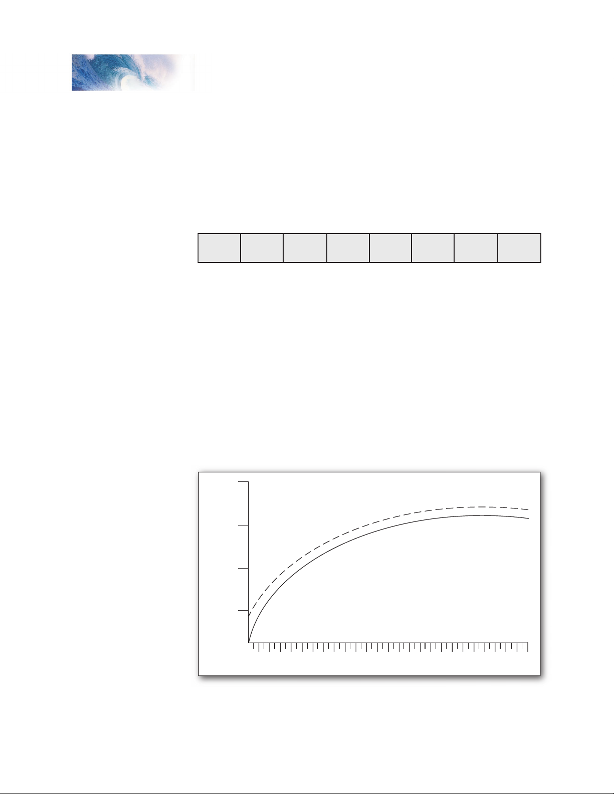
Vstart = 20
Vstart = 0
MOTOR VOLTAGE
100%
75%
50%
25%
0%
Vstart
Primary CVs
Description
Vstart defines the initial voltage level applied to the motor at speed step 1 as
a fraction of available supply voltage:
D0-D7: Motor Start Voltage
Vstart may contain any value from 0 to 255. The starting voltage applied to
the motor may be computed as:
Starting Voltage = Supply Voltage X CV2÷255
where CV 2 is the contents of the Vstart register. A value of 0 corresponds to
a zero starting voltage. A value of 255 corresponds to the maximum available
voltage (100%).
For speed steps greater than 1, the DSD will continue to sum the initial
starting voltage level into the throttle computations which has the effect of
offsetting all points on a given speed curve by the level set by Vstart as
illustrated in the figure below.
Default value: 0
Tsunami Technical Reference Page 2
Page 5

Tsunami Technical Reference Page 3
Primary CVs
Bit 7 Bit 0
D7 D6 D5 D4 D3 D2 D1 D0
CV 3
Baseline Acceleration Rate
Description
Contains a value between 0 and 255 that sets the decoder’s acceleration
rate:
D0-D7: Baseline Acceleration Rate
Acceleration rate may be computed as:
seconds/speed step = CV 3 x 0.896÷Number of speed steps
When this CV is set to 0, the locomotive speed will respond nearly instantly
to increases in the throttle setting, equivalent to no momentum. When set to
255, it will take approximately 3.8 minutes to accelerate to full speed from a
standing stop.
It is recommended that this CV be set to a nonzero value when operating the
DSD in 14 or 28 speed step modes as the throttle will interpolate between
speed steps during acceleration to produce a smoother overall response.
Default value: 0
Related CVs: See also Baseline Braking Rate, Consist Acceleration
Rate, Consist Brake Rate.
Tsunami Technical Reference Page 3
Page 6

Primary CVs
Bit 7 Bit 0
D7 D6 D5 D4 D3 D2 D1 D0
CV 4
Baseline Braking Rate
Description
Contains a value between 0 and 255 that sets the decoder’s braking rate:
D0-D7: Baseline Braking Rate
Braking rate may be computed as:
seconds/speed step = CV 3 x 0.896÷Number of speed steps
When this CV is set to 0, the locomotive speed will respond nearly instantly
to decreases in the throttle setting. When set to 255, it will take approximately
3.8 minutes to brake to a stop from full speed.
It is recommended that this CV be set to a nonzero value when operating the
DSD in 14 or 28 speed step modes as the throttle will interpolate between
speed steps during braking to produce a smoother overall response.
Default value: 0
Related CVs: See also Baseline Acceleration, Consist Acceleration
Rate, Consist Brake Rate.
Tsunami Technical Reference Page 4
Page 7

Tsunami Technical Reference Page 5
Primary CVs
Bit 7 Bit 0
D7 D6 D5 D4 D3 D2 D1 D0
CV 7
Manufacturer Version ID (Read Only)
Description
Contains 8-bit software version identifier.
D0-D7: Version Code
64 = Tsunami Steam Decoder, V1.0
65 = Tsunami Diesel Decoder, V1.0
This CV is read only and cannot be modified.
Tsunami Technical Reference Page 5
Page 8

Primary CVs
Bit 7 Bit 0
1 0 0 0 1 1 0 1
CV 8
Manufacturer ID
Description
Contains the NMRA issued Manufacturer ID code assignment for
SoundTraxx/Throttle Up! (141):
Writing a value of 8 to this CV will reset all CVs to their default value. All other
write operations will be ignored.
Tsunami Technical Reference Page 6
Page 9

Tsunami Technical Reference Page 7
Primary CVs
Bit 7 Bit 0
D7 D6 D5 D4 D3 D2 D1 D0
CV 10
BEMF Cutout
Description
This is used to gradually reduce the effect of the BEMF Control as locomotive
speed is increased. This CV contains a value from 0-127 that corresponds to
the speed step at which the intensity of BEMF control will be reduced to zero.
D0-D7: BEMF Cutout
This CV can alternatively contain a value from 128-255 which will cause
the BEMF intensity to decrease to a percentage between 0 and 50% of the
BEMF intensity set by CV 212 as:
Full Speed BEMF Intensity = (CV 212 – 128)÷128
Default value: 0
Tsunami Technical Reference Page 7
Page 10

Bit 7 Bit 0
D7 D6 D5 D4 D3 D2 D1 D0
Primary CVs
CV 11
Packet Time Out Value
Description
Contains a value between 0 and 255 corresponding to the time period that is
allowed to elapse between receipts of a valid packet addressed to the DSD
before a throttle shutdown occurs.
D0-D7: Packet Time-out Value
The time out period is computed in seconds as:
Time Out Period = CV 11 X 0.25
A CV value of 0 disables the time out period and the locomotive will run
indefinitely without receiving another packet.
For all other values, the DSD maintains an internal timer, which is reset every
time the DSD receives a valid broadcast address packet or other valid packet
whose address matches its primary address or, if enabled, the extended
address or consist address.
In the event no valid packets are received within the prescribed time period,
the DSD will bring the locomotive to a stop at the rate set by CV 4 and CV
24. The state of the auxiliary function outputs will remain unchanged.
Default value: 0
Tsunami Technical Reference Page 8
Page 11

Tsunami Technical Reference Page 9
Primary CVs
Bit 7 Bit 0
D7 D6 D5 D4 D3 D2 D1 D0
CV 12
Power Source Conversion
Description
Defines the type of power source the decoder should switch to whenever a
DCC signal is not present and the APS bit of CV 29 (bit 2) is set.
D0-D7: Alternate Power Source
0 = No Alternate Power Source Available
1 = Analog Power Supply
Default value: 1
Tsunami Technical Reference Page 9
Page 12

Primary CVs
Bit 7 Bit 0
F8 F7 F6 F5 F4 F3 F2 F1
CV 13
Analog Function Enable 1
Description
Defines whether functions 1-8 are active during analog mode operation. If
the bit is set, the corresponding function will be mapped to the output as
defined by CVs 33-46.
F1-F8: Analog Function Enable Bit
0 = Function is disabled for analog operation
1 = Function is enabled for analog operation
Default value: 0
Tsunami Technical Reference Page 10
Page 13

Tsunami Technical Reference Page 11
Primary CVs
Bit 7 Bit 0
F12 F11 F10 F9 F0 (r) F0 (f)
CV 14
Analog Function Enable 2
Description
Defines whether functions 9-12 are active during analog mode operation.
If the bit is set, the corresponding function will be mapped to the output as
defined by CVs 33-46.
F0 (f): F0 Forward Enable Bit
0 = Function is disabled for analog operation
1 = Function is enabled for analog operation
F0 (r): F0 Reverse Enable Bit
0 = Function is disabled for analog operation
1 = Function is enabled for analog operation
F9-F12: Analog Function Enable Bit
0 = Function is disabled for analog operation
1 = Function is enabled for analog operation
Default value: 3
Tsunami Technical Reference Page 11
Page 14

Primary CVs
Bit 7 Bit 0
0 0 0 0 0 D2 D1 D0
CV 15
CV Unlock Register
Description
Contains a value from 0-7 that is used to unlock access to the decoder’s CVs
in a multi-decoder installation.
CV 15 may always be written or verified regardless of the decoder’s lock
status. An acknowledgment will only be generated, however, when the
decoder is unlocked.
D0-D2: Unlock Code
Locked State
If CV 15 does not match CV 16, all read and write operations to the
decoder will be ignored and no acknowledgment is generated.
Unlocked State
Access to the decoder’s CVs occurs only when CV 15 = CV 16.
Note: CVLCKE Bit in CV 30 must be set to enable the lock feature in CVs
15 and 16.
Default value: 0
Related CVs: See also Error Information/Alternate Mode Selection.
Tsunami Technical Reference Page 12
Page 15

Tsunami Technical Reference Page 13
Primary CVs
Bit 7 Bit 0
0 0 0 0 0 ID2 ID1 ID0
CV 16
CV Lock ID Code
Description
Contains a value from 0-7 that sets the unlock code that must be
programmed into CV 15 in order to access the decoder’s CVs in a multidecoder installation.
CV 15 may always be written or verified regardless of the decoder’s lock
status. An acknowledgment will only be generated, however, when the
decoder is unlocked.
ID0-ID2: CV Lock Code
Note: CVLCKE Bit in CV 30 must be set to enable the lock feature in CVs
15 and 16.
Default Value: 0
Related CVs: See also Error Information/Alternate Mode Selection.
Tsunami Technical Reference Page 13
Page 16

Primary CVs
Bit 7 Bit 0
A15 A14 A13 A12 A11 A10 A9 A8
Bit 7 Bit 0
A7 A6 A5 A4 A3 A2 A1 A0
CV 17,18
Extended Address
Description
CV 17 and 18 make up a ‘paired’ CV, meaning that the two CV registers
taken together hold one piece of data; in this case, the 14-bit extended
decoder address:
CV 17 Extended Address MSB
CV 18 Extended Address LSB
A0-A15: Extended Address Value
The extended address allows the decoder to be assigned one of 10,179
addresses ranging from 0xC000 to 0xE7FF (Note however, that most
command stations will only recognize addresses 0000 through 9999.). The
extended address will only be recognized by the decoder when CV 29, bit
5 is set to 1. Once this bit is set, the decoder will no longer recognize its
primary address until CV 29, bit 5 is cleared.
CV 17 contains the most significant byte and must be loaded with values
within the range of 0xC0 and 0xE7. CV 18 contains the least significant byte
and may contain any value.
To determine the extended address value, add the desired four-digit address
to the number 49152. Divide this number by 256 and record the quotient and
the remainder. CV 17 is then programmed with the quotient value and CV 18
is programmed with the remainder value.
Example: Compute CV 17 and 18 register values for extended address 7152.
1. Add 7152 to 49152: Sum = 56304.
2. Divide 56304 by 256: Quotient = 219 Remainder = 240
3. Program CV 17 to 219
4. Program CV 18 to 240
Note: Most command stations will handle these computations automatically
Tsunami Technical Reference Page 14
Page 17

Tsunami Technical Reference Page 15
Primary CVs
when setting the extended address. However, it’s still nice to know how to
derive them.
Because CV 17 and 18 make up a paired CV, programming order is
important. CV 17 must be written to first, followed by a write to CV 18. The
decoder will ignore commands that attempt to program these registers out of
order or with values outside the allowed range of 0xC000 to 0xE7FF.
These CVs may be changed in service mode at any time, but in operations
mode only when CV 29, bit 5 is cleared (i.e., CV 1, Primary Address is
enabled).
Default Value: CV 17 = 192, CV 18 = 03 (Long Address 0003)
Related CVs: See also Primary Address, CV 29, Consist Address.
Tsunami Technical Reference Page 15
Page 18

Primary CVs
Bit 7 Bit 0
CDIR A6 A5 A4 A3 A2 A1 A0
CV 19
Consist Address
Description
Contains address and direction data for consist operation:
Bit 0-6: A0-A6, Consist Address Value
Bit 7: CDIR, Consist Direction
0 = Normal Direction
1 = Reverse Direction
The CDIR bit defines orientation of the locomotive within a consist and
specifies whether the direction bit in a speed/direction data packet should be
inverted.
Bits A0-A6 assigns the consist address from 0 to 127. If A0-A6 = 00, consist
commands are ignored. Otherwise, if the decoder receives a valid command
packet whose address matches the consist address, the packet will be
processed as any other packet with the following exceptions:
Long Form CV Access instructions will be ignored.
The direction bit in a speed/direction or advanced operation packet is
inverted if CDIR = 1.
Only the auxiliary functions enabled in CV 21 and CV 22 are allowed to
change.
When the consist address is active, speed/direction and advanced operations
packets sent to the decoder’s primary address (or extended address, if
enabled) will be ignored. All other instruction packets sent to the decoder’s
primary (or extended) address, including CV access and function control, will
continue to be processed as normal.
In summary, setting CV 19 to 0 or 128 disables consist addressing. Setting
CV to a value between 1 and 127 enables consist addresses 1 to 127
with the locomotive oriented facing forward in the consist. Setting CV to a
value between 129 and 255 enables consist addresses 1 to 127 with the
locomotive oriented facing backwards in the consist.
Default Value: 0
Related CVs: See also Primary Address, Consist Function Active,
Consist F0 Function Active.
Tsunami Technical Reference Page 16
Page 19

Tsunami Technical Reference Page 17
Primary CVs
Bit 7 Bit 0
F7 F6 F5 F4 F3 F2 F1 F0
CV 21
Consist Function Group 1
Description
Defines which Group 1 functions may be controlled by packets sent to the
decoder’s consist address. Disabled functions may be controlled only from
decoder’s primary or extended address:
Bit 0: F1, Consist Function 1 Enable Bit
0 = function is disabled for consist operation.
1 = function is enabled for consist operation.
Bit 1: F2, Consist Function 2 Enable Bit
0 = function is disabled for consist operation.
1 = function is enabled for consist operation.
Bit 2: F3, Consist Function 3 Enable Bit
0 = function is disabled for consist operation.
1 = function is enabled for consist operation.
Bit 3: F4, Consist Function 4 Enable Bit
0 = function is disabled for consist operation.
1 = function is enabled for consist operation.
Bit 4: F5, Consist Function 5 Enable Bit
0 = function is disabled for consist operation.
1 = function is enabled for consist operation.
Bit 5: F6, Consist Function 6 Enable Bit
0 = function is disabled for consist operation.
1 = function is enabled for consist operation.
Bit 6: F7, Consist Function 7 Enable Bit
0 = function is disabled for consist operation.
1 = function is enabled for consist operation.
Bit 7: F8, Consist Function 8 Enable Bit
0 = function is disabled for consist operation.
1 = function is enabled for consist operation.
This register is useful for differentiating the lead engine in the consist from
the other engines. For example, by setting this register in the lead locomotive
Tsunami Technical Reference Page 17
Page 20

Primary CVs
to 2 and the same register in all other engines to 0, only the whistle on the
lead locomotive will blow when the command to turn on Function 2 is sent to
the consist.
Default Value: 0
Related CVs: See also Consist Address, Consist F0 Function Active.
Consist F0 Function Active.
Tsunami Technical Reference Page 18
Page 21

Tsunami Technical Reference Page 19
Primary CVs
Bit 7 Bit 0
F12 F11 F10 F9 F0 (r) F0 (f)
CV 22
Consist Function Group 2
Description
Defines which Group 2 functions may be controlled by packets sent to the
decoder’s consist address. Disabled functions may be controlled only from
decoder’s primary or extended address:
Bit 0: F0(f), Function 0, Forward enable Bit
0 = function is disabled for consist operation.
1 = function is enabled for consist operation.
Bit 1: F0(r), Function 0, Reverse enable Bit
0 = function is disabled for consist operation.
1 = function is enabled for consist operation.
Bit 2: F9, Consist Function 9 Enable Bit
0 = function is disabled for consist operation.
1 = function is enabled for consist operation.
Bit 3: F10, Consist Function 10 Enable Bit
0 = function is disabled for consist operation.
1 = function is enabled for consist operation.
Bit 4: F11, Consist Function 11 Enable Bit
0 = function is disabled for consist operation.
1 = function is enabled for consist operation.
Bit 5: F12, Consist Function 12 Enable Bit
0 = function is disabled for consist operation.
1 = function is enabled for consist operation.
Bit 6: Reserved.
Bit 7: Reserved.
This register is useful for differentiating the Headlight and Backup Light
functions in the lead engine of the consist from the other engines. For
example, by setting this register in the lead locomotive to 1 and the same
register in all other engines to 0, only the headlight in the lead engine will be
on and only when the consist is moving forward.
Default Value: 0
Related CVs: See also Consist Address, Consist Function Active.
Tsunami Technical Reference Page 19
Page 22

Primary CVs
Bit 7 Bit 0
sign D6 D5 D4 D3 D2 D1 D0
CV 23
Consist Acceleration Rate
Description
Contains a value between -127 to +127 corresponding to the decoder’s
consist acceleration offset:
Bits 0-6: D0-D6, Consist Acceleration value
Bit 7: Sign
0 = positive value
1 = negative value
When the consist address is active, the consist acceleration rate is added to
or subtracted from the decoder’s base acceleration rate depending on the
sign bit. The acceleration is then computed as:
seconds/speed step = (CV 3 + CV 23) x 0.896÷Number of speed steps
If the sum of CV 3 and CV 23 is negative, then the acceleration rate is set to
0 (i.e., acceleration is instant.) If the sum of CV 3 and CV 23 exceeds 255,
then the acceleration rate is set to the maximum value of 255.
This CV has no effect when the consist address is set to 0.
In summary, a CV value between 0 and 127 will increase the decoder’s base
acceleration rate. Values between 128 and 255 will decrease the decoder’s
base acceleration rate.
Default value: 0
Related CVs: See also Baseline Acceleration Rate, Baseline Braking
Rate, Consist Brake Rate.
Tsunami Technical Reference Page 20
Page 23

Tsunami Technical Reference Page 21
Primary CVs
Bit 7 Bit 0
sign D6 D5 D4 D3 D2 D1 D0
CV 24
Consist Braking Rate
Description
Contains a value between -127 to +127 corresponding to the decoder’s
consist braking offset:
Bits 0-6: D0-D6, Consist Braking value
Bit 7: Sign
0 = positive value
1 = negative value
When the consist address is active, the consist braking rate is added to or
subtracted from the decoder’s baseline braking rate depending on the sign
bit. The braking rate is then computed as:
seconds/speed step = (CV 4 + CV 24) x 0.896÷Number of speed steps
If the sum of CV 4 and CV 24 is negative, then the braking rate is set to 0
(i.e., braking is instant.) If the sum of CV 4 and CV 24 exceeds 255, then the
braking rate is set to the maximum value of 255.
This CV has no effect when the consist address is set to 0.
In summary, a CV value between 0 and 127 will increase the decoder’s base
braking rate. Values between 128 and 255 will decrease the decoder’s base
braking rate.
Default value: 0
Related CVs: See also Baseline Acceleration Rate, Baseline Braking
Rate, Consist Acceleration Rate.
Tsunami Technical Reference Page 21
Page 24

Primary CVs
Bit 7 Bit 0
MIDSPD
D6 D5 D4 D3 D2 D1 D0
CV 25
Speed Table Select Register
Description
Used to select one of 15 Speed Curves:
D0-D6: Table Identifier/Speed Step Value
MIDSPD: 0 = Factory Speed Table Select
1 = Mid Range Speed (Not used)
When MIDSPD = 0, D0-D6 defines which preset factory speed table is used.
0 = Disabled, Speed Curves not used
1 = Disabled, Speed Curves not used
2 = Linear Speed Curve
3 = Logarithmic Curve 1
4 = Logarithmic Curve 2
5 = Logarithmic Curve 3
6 = Logarithmic Curve 4
7 = Logarithmic Curve 5
8 = Logarithmic Curve 6
9 = Logarithmic Curve 7
10 = Exponential Curve 1
11 = Exponential Curve 2
12 = Exponential Curve 3
13 = Exponential Curve 4
14 = Exponential Curve 5
15 = Exponential Curve 6
16 = User Defined Speed Table defined by CVs 67-94.
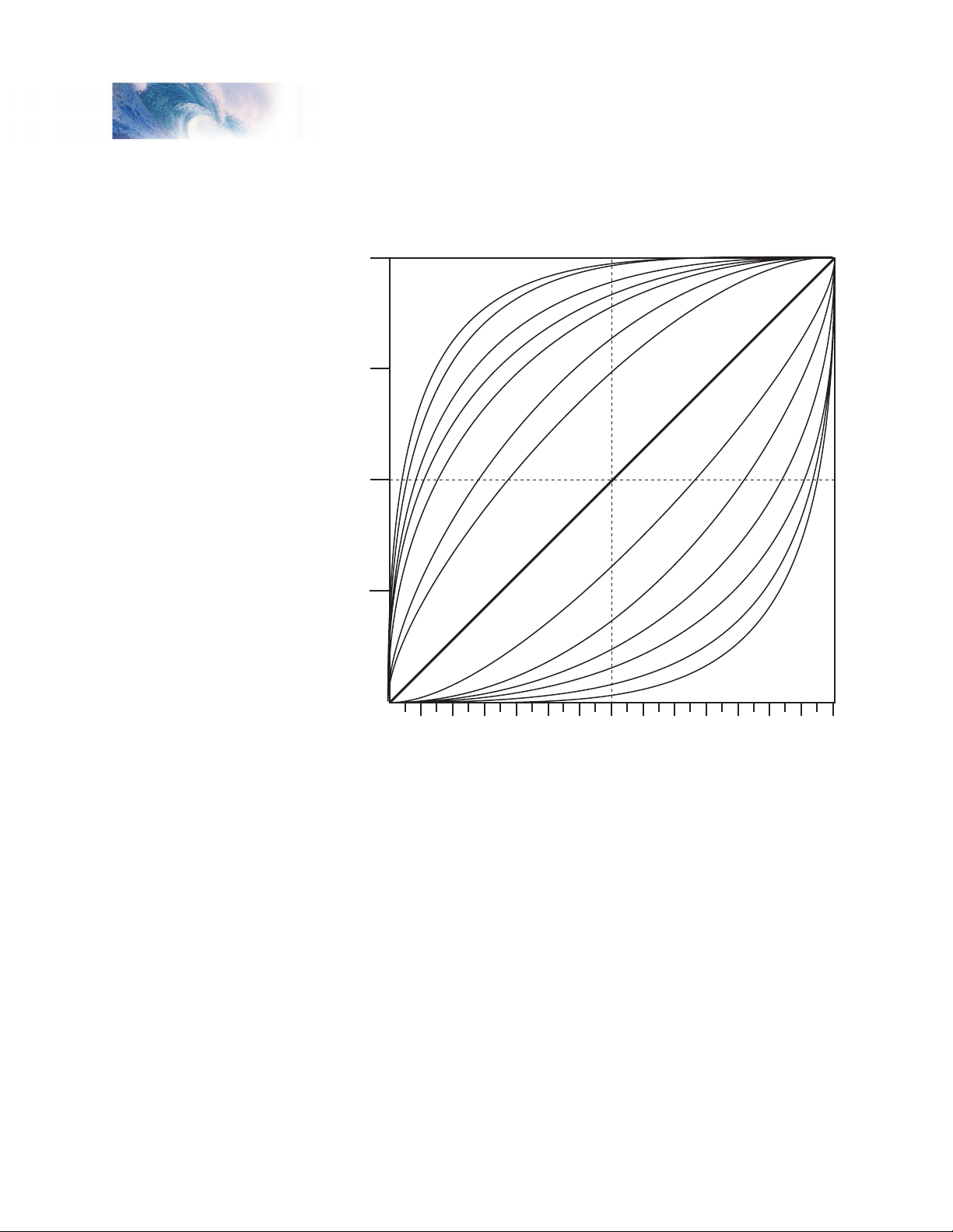
CV 25 may be programmed with any value between 0 and 31. Values
between 2 and 15 allow the user to select from one of 14 predefined speed
curves as depicted below. The logarithmic curves provide a shallower
speed response as the throttle is increased. These curves are useful for
locomotives that require a high starting voltage to get moving or matching
a highly geared locomotive to one that has less gearing. The exponential
curves are useful for slowing down locomotives that have a “slot car”
response.
Setting this CV to a value of 16 will enable the speed curve programmed into
CVs 67-94. This curve may be programmed by the user to get virtually any
response desired.
Tsunami Technical Reference Page 22
Page 25
Tsunami Technical Reference Page 23
Primary CVs
100%
75%
50%
25%
0%
0 2 4 6 8 10 12 14 16 18 20 22 24 26 28
LOG
7
LOG 5
LOG 6
LOG 3
LOG
2
LOG
1
LOG
4
LINEAR
EXP
1
EXP
2
EXP
3
EXP
4
EXP
5
EXP
6
Note that in order for the selected curve to be active, bit 4 of CV 29 must also
be set to 1. If CV 29, bit 4 is 0, the throttle response will be linear (straight
line).
The speed curves can be used in 14, 28 and 128 speed step modes.
Tsunami Technical Reference Page 23
Bit 7 is defined by the NMRA RPs as the Mid Range Speed Step select bit.
The DSD does not implement this feature and will ignore commands that
attempt to program this bit with a 1 (i.e., data values between 128-255).
Default value: 0
Related CVs: See also CV 29, Loadable Speed Table.
Page 26

Primary CVs
Bit 7 Bit 0
0 0 EAM STE ACK APS F0 DIR
CV 29
Configuration Register 1
Description
CV 29 contains miscellaneous decoder configuration bits:
Bit 0: DIR, Direction Bit
0 = normal operation
1 = direction bit in Speed/Direction instruction is inverted
before processing.
Bit 1: F0 Location
0 = F0 state is controlled by bit 4 of Speed/Direction
Instruction (14 Speed Step Mode)
1 = F0 state is controlled by bit 4 of Function Group 1
Instruction (28 and 128 Speed Step Modes)
Bit 2: APS, Alternate Power Source enable
0 = NMRA Digital Only
1 = Alternate Power Source enabled as set by CV 12
Bit 3: ACK, Advanced Acknowledge Mode enable (not used)
0 = Advanced Acknowledge mode disabled.
1 = Advanced Acknowledge mode enabled.
Bit 4: STE, Speed Table Enable
0 = Speed Table set by CV 2, 4 and 6.
1 = Use custom speed table selected by CV 25.
Bit 5: EAM, Extended Address Mode enable
0 = Decoder responds to Primary Address in CV 1
1 = Decoder responds to Extended Address in CV 17-18
Bit 6: Reserved for future use.
Bit 7: Multifunction Decoder - Always reads as 0.
When the DIR bit is set, the locomotive and headlight will run in a direction
opposite to the speed/direction instruction received. This bit is mostly useful
for diesel locomotives that are run long hood forward and has little use for
steam operation.
The F0 bit should be cleared to 0 if you are using the decoder in 14 speed
step mode. If you are using 28 or 128 speed step modes, this bit should be
Tsunami Technical Reference Page 24
Page 27

Tsunami Technical Reference Page 25
Primary CVs
set to 1.
The STE bit must be set to 1 in order to enable any of the speed curves
selected using CV 25. Otherwise, the DSD will provide a linear (straight-line)
throttle response.
The EAM bit must be set to 1 in order to activate extended address
capability. Note that once this bit is set, the decoder will respond to
commands sent to the extended address only and commands sent to the
primary address will be ignored. This can be a problem if you are using
a command station that does not support extended addressing and the
bit gets accidentally set. In such a case, you must connect the DSD to a
programming track to gain access to the CV and clear the bit.
The APS bit must be set to 1 in order to activate an alternate power mode as
set in CV 12. To activate Analog Mode Operation, you must also set CV 12 to
1.
The DSD does not support advanced acknowledgment and the ACK bit will
always read as 0.
Default value: 2
Related CVs: See also Extended Address, Loadable Speed Table.
Tsunami Technical Reference Page 25
Page 28

Primary CVs
Bit 7 Bit 0
GRP23 CVCLR CVLCKE
CV 30
Error Information/Alternate Mode Selection
Description
Contains manufacturer defined error codes and provides feedback in the
event an operational failure occurred within the DSD. It is also used to reconfigure the decoder for non-NMRA compliant options:
Bit 0: CVLCKE, CV Lock Enable
0 = Normal operation.
1 = Enables CV Lock as set in CVs 15 and 16.
Bit 1: CVCLR, CV Clear
0 = Normal operation.
1 = All CVs will be reset to default values at next power
cycle.
Bit 2: GRP23, Function Group 2 and 3 Exchange
0 = System Normal, DSD processes group 2 and 3
function commands according to the NMRA standard.
1 = Function Group 2 (F5-F8) assignments are swapped
with Function Group 3 (F9-F12)
Bits 3-7: Reserved.
Default value: 0
Related CVs: See also CV Unlock Register, CV Lock ID Code.
Tsunami Technical Reference Page 26
Page 29

Tsunami Technical Reference Page 27
Function Output CVs
33
34
35
36
37
38
39
40
41
42
43
44
45
46
128
128
128
128
16
16
16
16
2
2
2
1
1
1
64
64
64
64
8
8
8
8
1
1
1
32
32
32
32
4
4
4
4
X
16
16
16
16
2
2
2
2
X
8
8
8
8
1
1
1
1
X
4
4
4
4
2
2
2
2
1
1
1
1
32
32
32
32
4
4
4
2
2
2
64
64
64
64
8
8
8
4
4
4
128
128
128
128
16
16
16
8
8
8
X
X
X
32
32
32
16
16
16
64
64
64
32
32
32
128
128
128
64
64
64
128
128
128
Control CV
F0 (f)
F0 (r)
F1
F2
F3
F4
F5
F6
F7
F8
F9
F10
F11
F12
Function Key
HL
BL
WH
BEL
SHW
STM
WS
FX5
DY
N
FX6
Function Mapping Table
DIM
MUT
INJ
BRK
CPL
Bold Numbers indicate default settings.
CV 33-46
Function Output Map
CVs 33-46 allow the user to customize which DSD outputs or sound effects
are controlled by which function keys. Each function input, F0 through F12,
is assigned a unique CV that allows the corresponding function control to be
redirected to up to fifteen different DSD function outputs or sound effects.
This allows a single function key to control more than one output if desired.
The F0 function has two CVs - one for forward direction and one for reverse.
Function outputs mapped to these registers will be directional unless the
same output is mapped to both CVs.
Note that all function inputs cannot be mapped to all outputs. The matrix
below graphically indicates which inputs can control which outputs:
Tsunami Technical Reference Page 27
Page 30

Function Output CVs
Bit 7
Steam:
Bit 0
SHW DYN FX6 FX5 BEL WH BL HL
CV 33
F0(f) Output Location
Description
Maps the F0(f) function to any of eight DSD auxiliary function outputs as
defined by a 1 in the corresponding bit position:
Bit 0: HL, Head light output
0 = Output is unaffected by F0(fwd).
1 = Output is activated when F0(fwd) is on.
Bit 1: BL, Backup light output
0 = Output is unaffected by F0(fwd).
1 = Output is activated when F0(fwd) is on.
Bit 2: WH, Whistle Sound Effect
0 = Sound is unaffected by F0(fwd).
1 = Sound is activated when F0(fwd) is on.
Bit 3: BEL, Bell Sound Effect
0 = Sound is unaffected by F0(fwd).
1 = Sound is activated when F0(fwd) is on.
Bit 4: FX5, Effect 1 output
0 = Output is unaffected by F0(fwd).
1 = Output is activated when F0(fwd) is on.
Bit 5: FX6, Effect 2 output
0 = Output is unaffected by F0(fwd).
1 = Output is activated when F0(fwd) is on.
Bit 6: DYN, Dynamo Sound Effect
0 = Sound is unaffected by F0(fwd).
1 = Sound is activated when F0(fwd) is on.
Bit 7: SHW, Short Whistle Sound Effect
0 = Sound is unaffected by F0(fwd).
1 = Sound is activated when F0(fwd) is on.
Default Value: 65
Related CVs: See also CVs 34-46
Tsunami Technical Reference Page 28
Page 31

Tsunami Technical Reference Page 29
Function Output CVs
Bit 7
Steam:
Bit 0
SHW DYN FX6 FX5 BEL WH BL HL
CV 34
F0(r) Output Location
Description
Maps the F0(rev) function to any of eight DSD auxiliary function outputs as
defined by a 1 in the corresponding bit position:
Bit 0: HL, Head light output
0 = Output is unaffected by F0(rev).
1 = Output is activated when F0(rev) is on.
Bit 1: BL, Backup light output
0 = Output is unaffected by F0(rev).
1 = Output is activated when F0(rev) is on.
Bit 2: WH, Whistle Sound Effect
0 = Sound is unaffected by F0(rev).
1 = Sound is activated when F0(rev) is on.
Bit 3: BEL, Bell Sound Effect
0 = Sound is unaffected by F0(rev).
1 = Sound is activated when F0(rev) is on.
Bit 4: FX5, Effect 1 output
0 = Output is unaffected by F0(rev).
1 = Output is activated when F0(rev) is on.
Bit 5: FX6, Effect 2 output
0 = Output is unaffected by F0(rev).
1 = Output is activated when F0(rev) is on.
Bit 6: DYN, Dynamo Sound Effect
0 = Sound is unaffected by F0(rev).
1 = Sound is activated when F0(rev) is on.
Bit 7: SHW, Short Whistle Sound Effect
0 = Sound is unaffected by F0(rev).
1 = Sound is activated when F0(rev) is on.
Default Value: 66
Related CVs: See also CVs 33, 35-46
Tsunami Technical Reference Page 29
Page 32

Function Output CVs
Bit 7
Steam:
Bit 0
SHW DYN FX6 FX5 BEL WH BL HL
CV 35
F1 Output Location
Description
Maps the F1 function to any of eight DSD auxiliary function outputs as
defined by a 1 in the corresponding bit position:
Bit 0: HL, Head light output
0 = Output is unaffected by F1.
1 = Output is activated when F1 is on.
Bit 1: BL, Backup light output
0 = Output is unaffected by F1.
1 = Output is activated when F1 is on.
Bit 2: WH, Whistle Sound Effect
0 = Sound is unaffected by F1.
1 = Sound is activated when F1 is on.
Bit 3: BEL, Bell Sound Effect
0 = Sound is unaffected by F1.
1 = Sound is activated when F1 is on.
Bit 4: FX5, Effect 1 output
0 = Output is unaffected by F1.
1 = Output is activated when F1 is on.
Bit 5: FX6, Effect 2 output
0 = Output is unaffected by F1.
1 = Output is activated when F1 is on.
Bit 6: DYN, Dynamo Sound Effect
0 = Sound is unaffected by F1.
1 = Sound is activated when F1 is on.
Bit 7: SHW, Short Whistle Sound Effect
0 = Sound is unaffected by F1.
1 = Sound is activated when F1 is on.
Default Value: 8
Related CVs: See also CVs 33-34, 36-46
Tsunami Technical Reference Page 30
Page 33

Tsunami Technical Reference Page 31
Function Output CVs
Bit 7
Steam:
Bit 0
SHW DYN FX6 FX5 BEL WH BL HL
CV 36
F2 Output Location
Description
Maps the F2 function to any of eight DSD auxiliary function outputs as
defined by a 1 in the corresponding bit position:
Bit 0: HL, Head light output
0 = Output is unaffected by F2.
1 = Output is activated when F2 is on.
Bit 1: BL, Backup light output
0 = Output is unaffected by F2.
1 = Output is activated when F2 is on.
Bit 2: WH, Whistle Sound Effect
0 = Sound is unaffected by F2.
1 = Sound is activated when F2 is on.
Bit 3: BEL, Bell Sound Effect
0 = Sound is unaffected by F2.
1 = Sound is activated when F2 is on.
Bit 4: FX5, Effect 1 output
0 = Output is unaffected by F2.
1 = Output is activated when F2 is on.
Bit 5: FX6, Effect 2 output
0 = Output is unaffected by F2.
1 = Output is activated when F2 is on.
Bit 6: DYN, Dynamo Sound Effect (Steam)
0 = Sound is unaffected by F2.
1 = Sound is activated when F2 is on.
Bit 7: SHW, Short Whistle Sound Effect
0 = Sound is unaffected by F2.
1 = Sound is activated when F2 is on.
Default Value: 4
Related CVs: See also CVs 33-35, 37-46
Tsunami Technical Reference Page 31
Page 34

Function Output CVs
Bit 7
Steam:
Bit 0
DIM WS STM SHW DYN FX6 FX5 BEL
CV 37
F3 Output Location
Description
Maps the F3 function to any of eight DSD auxiliary function outputs as
defined by a 1 in the corresponding bit position:
Bit 0: BEL, Bell Sound Effect
0 = Sound is unaffected by F3.
1 = Sound is activated when F3 is on.
Bit 1: FX5, Effect 1 output
0 = Output is unaffected by F3.
1 = Output is activated when F3 is on.
Bit 2: FX6, Effect 2 output
0 = Output is unaffected by F3.
1 = Output is activated when F3 is on.
Bit 3: DYN, Dynamo Sound Effect
0 = Sound is unaffected by F3.
1 = Sound is activated when F3 is on.
Bit 4: SHW, Short Whistle Sound Effect
0 = Sound is unaffected by F3.
1 = Sound is activated when F3 is on.
Bit 5: STM, Steam Release/Cylinder Cocks
0 = Sound is unaffected by F3.
1 = Sound is activated when F3 is on.
Bit 6: WS, Water Stop
0 = Sound is unaffected by F3.
1 = Sound is activated when F3 is on.
Bit 7: DIM, Headlight Dimmer Function
0 = Lighting outputs are unaffected by F3.
1 = Lighting outputs set up as “Dimmable Headlights”
are dimmed when F3 is on.
Default Value: 16
Related CVs: See also CVs 33-36, 38-46
Tsunami Technical Reference Page 32
Page 35

Tsunami Technical Reference Page 33
Function Output CVs
Bit 7
Steam:
Bit 0
DIM WS STM SHW DYN FX6 FX5 BEL
CV 38
F4 Output Location
Description
Maps the F4 function to any of eight DSD auxiliary function outputs as
defined by a 1 in the corresponding bit position:
Bit 0: BEL, Bell Sound Effect
0 = Sound is unaffected by F4.
1 = Sound is activated when F4 is on.
Bit 1: FX5, Effect 1 output
0 = Output is unaffected by F4.
1 = Output is activated when F4 is on.
Bit 2: FX6, Effect 2 output
0 = Output is unaffected by F4.
1 = Output is activated when F4 is on.
Bit 3: DYN, Dynamo Sound Effect
0 = Sound is unaffected by F4.
1 = Sound is activated when F4 is on.
Bit 4: SHW, Short Whistle Sound Effect
0 = Sound is unaffected by F4.
1 = Sound is activated when F4 is on.
Bit 5: STM, Steam Release/Cylinder Cocks
0 = Sound is unaffected by F4.
1 = Sound is activated when F4 is on.
Bit 6: WS, Water Stop
0 = Sound is unaffected by F4.
1 = Sound is activated when F4 is on.
Bit 7: DIM, Headlight Dimmer Function
0 = Lighting outputs are unaffected by F4.
1 = Lighting outputs set up as “Dimmable Headlights”
are dimmed when F4 is on.
Default Value: 32
Related CVs: See also CVs 33-37, 39-46
Tsunami Technical Reference Page 33
Page 36

Function Output CVs
Bit 7
Steam:
Bit 0
DIM WS STM SHW DYN FX6 FX5 BEL
CV 39
F5 Output Location
Description
Maps the F5 function to any of eight DSD auxiliary function outputs as
defined by a 1 in the corresponding bit position:
Bit 0: BEL, Bell Sound Effect
0 = Sound is unaffected by F5.
1 = Sound is activated when F5 is on.
Bit 1: FX5, Effect 1 output
0 = Output is unaffected by F5.
1 = Output is activated when F5 is on.
Bit 2: FX6, Effect 2 output
0 = Output is unaffected by F5.
1 = Output is activated when F5 is on.
Bit 3: DYN, Dynamo Sound Effect
0 = Sound is unaffected by F5.
1 = Sound is activated when F5 is on.
Bit 4: SHW, Short Whistle Sound Effect
0 = Sound is unaffected by F5.
1 = Sound is activated when F5 is on.
Bit 5: STM, Steam Release/Cylinder Cocks
0 = Sound is unaffected by F5.
1 = Sound is activated when F5 is on.
Bit 6: WS, Water Stop
0 = Sound is unaffected by F5.
1 = Sound is activated when F5 is on.
Bit 7: DIM, Headlight Dimmer Function
0 = Lighting outputs are unaffected by F5.
1 = Lighting outputs set up as “Dimmable Headlights”
are dimmed when F5 is on.
Default Value: 2
Related CVs: See also CVs 33-38, 40-46
Tsunami Technical Reference Page 34
Page 37

Tsunami Technical Reference Page 35
Function Output CVs
Bit 7
Steam:
Bit 0
DIM WS STM SHW DYN FX6 FX5 BEL
CV 40
F6 Output Location
Description
Maps the F6 function to any of eight DSD auxiliary function outputs as
defined by a 1 in the corresponding bit position:
Bit 0: BEL, Bell Sound Effect
0 = Sound is unaffected by F6.
1 = Sound is activated when F6 is on.
Bit 1: FX5, Effect 1 output
0 = Output is unaffected by F6.
1 = Output is activated when F6 is on.
Bit 2: FX6, Effect 2 output
0 = Output is unaffected by F6.
1 = Output is activated when F6 is on.
Bit 3: DYN, Dynamo Sound Effect
0 = Sound is unaffected by F6.
1 = Sound is activated when F6 is on.
Bit 4: SHW, Short Whistle Sound Effect
0 = Sound is unaffected by F6.
1 = Sound is activated when F6 is on.
Bit 5: STM, Steam Release/Cylinder Cocks
0 = Sound is unaffected by F6.
1 = Sound is activated when F6 is on.
Bit 6: WS, Water Stop
0 = Sound is unaffected by F6.
1 = Sound is activated when F6 is on.
Bit 7: DIM, Headlight Dimmer Function
0 = Lighting outputs are unaffected by F6.
1 = Lighting outputs set up as “Dimmable Headlights”
are dimmed when F6 is on.
Default Value:
Related CVs: See also CVs 33-39, 41-46
4
Tsunami Technical Reference Page 35
Page 38

Function Output CVs
Bit 7
Steam:
Bit 0
BRK INJ MUT DIM WS STM SHW DYN
CV 41
F7 Output Location
Description
Maps the F7 function to any of eight DSD auxiliary function outputs as
defined by a 1 in the corresponding bit position:
Bit 0: DYN, Dynamo Sound Effect
0 = Sound is unaffected by F7.
1 = Sound is activated when F7 is on.
Bit 1: SHW, Short Whistle Sound Effect
0 = Sound is unaffected by F7.
1 = Sound is activated when F7 is on.
Bit 2: STM, Steam Release/Cylinder Cocks
0 = Sound is unaffected by F7.
1 = Sound is activated when F7 is on.
Bit 3: WS, Water Stop
0 = Sound is unaffected by F7.
1 = Sound is activated when F7 is on.
Bit 4: DIM, Headlight Dimmer Function
0 = Lighting outputs are unaffected by F7.
1 = Lighting outputs set up as “Dimmable Headlights” are
dimmed when F7 is on.
Bit 5: MUT, Audio Mute
0 = Sound is unaffected by F7.
1 = Sound is muted when F7 is on.
Bit 6: INJ, Injector Sound Effect
0 = Sound is unaffected by F7.
1 = Sound is activated when F7 is on.
Bit 7: BRK, Brake Squeal/Brake Release
0 = Sound is unaffected by F7.
1 = Sound is activated when F7 is on.
Default Value: 16
Related CVs: See also CVs 33-40, 42-46
Tsunami Technical Reference Page 36
Page 39

Tsunami Technical Reference Page 37
Function Output CVs
Bit 7
Steam:
Bit 0
BRK INJ MUT DIM WS STM SHW DYN
CV 42
F8 Output Location
Description
Maps the F8 function to any of eight DSD auxiliary function outputs as
defined by a 1 in the corresponding bit position:
Bit 0: DYN, Dynamo Sound Effect
0 = Sound is unaffected by F8.
1 = Sound is activated when F8 is on.
Bit 1: SHW, Short Whistle Sound Effect
0 = Sound is unaffected by F8.
1 = Sound is activated when F8 is on.
Bit 2: STM, Steam Release/Cylinder Cocks
0 = Sound is unaffected by F8.
1 = Sound is activated when F8 is on.
Bit 3: WS, Water Stop
0 = Sound is unaffected by F8.
1 = Sound is activated when F8 is on.
Bit 4: DIM, Headlight Dimmer Function
0 = Lighting outputs are unaffected by F8.
1 = Lighting outputs set up as “Dimmable Headlights”
are dimmed when F8 is on.
Bit 5: MUT, Audio Mute
0 = Sound is unaffected by F8.
1 = Sound is muted when F8 is on.
Bit 6: INJ, Injector Sound Effect
0 = Sound is unaffected by F8.
1 = Sound is activated when F8 is on.
Bit 7: BRK, Brake Squeal/Brake Release
0 = Sound is unaffected by F8.
1 = Sound is activated when F8 is on.
Default Value:
Related CVs: See also CVs 33-41, 43-46
Tsunami Technical Reference Page 37
32
Page 40

Function Output CVs
Bit 7
Steam:
Bit 0
BRK INJ MUT DIM WS STM SHW DYN
CV 43
F9 Output Location
Description
Maps the F9 function to any of eight DSD auxiliary function outputs as
defined by a 1 in the corresponding bit position:
Bit 0: DYN, Dynamo Sound Effect
0 = Sound is unaffected by F9.
1 = Sound is activated when F9 is on.
Bit 1: SHW, Short Whistle Sound Effect
0 = Sound is unaffected by F9.
1 = Sound is activated when F9 is on.
Bit 2: STM, Steam Release/Cylinder Cocks
0 = Sound is unaffected by F9.
1 = Sound is activated when F9 is on.
Bit 3: WS, Water Stop
0 = Sound is unaffected by F9.
1 = Sound is activated when F9 is on.
Bit 4: DIM, Headlight Dimmer Function
0 = Lighting outputs are unaffected by F9.
1 = Lighting outputs set up as “Dimmable Headlights”
are dimmed when F9 is on.
Bit 5: MUT, Audio Mute
0 = Sound is unaffected by F9.
1 = Sound is muted when F9 is on.
Bit 6: INJ, Injector Sound Effect
0 = Sound is unaffected by F9.
1 = Sound is activated when F9 is on.
Bit 7: BRK, Brake Squeal/Brake Release
0 = Sound is unaffected by F9.
1 = Sound is activated when F9 is on.
Default Value:
Related CVs: See also CVs 33-42, 44-46
Tsunami Technical Reference Page 38
8
Page 41

Tsunami Technical Reference Page 39
Function Output CVs
Bit 7
Steam:
Bit 0
CPL BRK INJ MUT DIM WS STM SHW
CV 44
F10 Output Location
Description
Maps the F10 function to any of eight DSD auxiliary function outputs as
defined by a 1 in the corresponding bit position:
Bit 0: SHW, Short Whistle Sound Effect
0 = Sound is unaffected by F10.
1 = Sound is activated when F10 is on.
Bit 1: STM, Steam Release/Cylinder Cocks
0 = Sound is unaffected by F10.
1 = Sound is activated when F10 is on.
Bit 2: WS, Water Stop
0 = Sound is unaffected by F10.
1 = Sound is activated when F10 is on.
Bit 3: DIM, Headlight Dimmer Function
0 = Lighting outputs are unaffected by F10.
1 = Lighting outputs set up as “Dimmable Headlights” are
dimmed when F10 is on.
Bit 4: MUT, Audio Mute
0 = Sound is unaffected by F10.
1 = Sound is muted when F10 is on.
Bit 5: INJ, Injector Sound Effect
0 = Sound is unaffected by F10.
1 = Sound is muted when F10 is on.
Bit 6: BRK, Brake Squeal/Brake Release
0 = Sound is unaffected by F10.
1 = Sound is activated when F10 is on.
Bit 7: CPL, Coupler Sound Effect
0 = Sound is unaffected by F10.
1 = Sound is activated when F10 is on.
Default Value: 32
Related CVs: See also CVs 33-43, 45-46
Tsunami Technical Reference Page 39
Page 42

Bit 7
Steam:
Bit 0
CPL BRK INJ MUT DIM WS STM SHW
Function Output CVs
CV 45
F11 Output Location
Description
Maps the F11 function to any of eight DSD auxiliary function outputs as
defined by a 1 in the corresponding bit position:
Bit 0: SHW, Short Whistle Sound Effect
0 = Sound is unaffected by F11.
1 = Sound is activated when F11 is on.
Bit 1: STM, Steam Release/Cylinder Cocks
0 = Sound is unaffected by F11.
1 = Sound is activated when F11 is on.
Bit 2: WS, Water Stop
0 = Sound is unaffected by F11.
1 = Sound is activated when F11 is on.
Bit 3: DIM, Headlight Dimmer Function
0 = Lighting outputs are unaffected by F11.
1 = Lighting outputs set up as “Dimmable Headlights” are
dimmed when F11 is on.
Bit 4: MUT, Audio Mute
0 = Sound is unaffected by F11.
1 = Sound is muted when F11 is on.
Bit 5: INJ, Injector Sound Effect
0 = Sound is unaffected by F11.
1 = Sound is muted when F11 is on.
Bit 6: BRK, Brake Squeal/Brake Release
0 = Sound is unaffected by F11.
1 = Sound is activated when F11 is on.
Bit 7: CPL, Coupler Sound Effect
0 = Sound is unaffected by F11.
1 = Sound is activated when F11 is on.
Default Value:
Related CVs: See also CVs 33-44, 46
Tsunami Technical Reference Page 40
64
Page 43

Tsunami Technical Reference Page 41
Bit 7
Steam:
Bit 0
CPL BRK INJ MUT DIM WS STM SHW
Function Output CVs
CV 46
F12 Output Location
Description
Maps the F12 function to any of eight DSD auxiliary function outputs as
defined by a 1 in the corresponding bit position:
Bit 0: SHW, Short Whistle Sound Effect
0 = Sound is unaffected by F12.
1 = Sound is activated when F12 is on.
Bit 1: STM, Steam Release/Cylinder Cocks
0 = Sound is unaffected by F12.
1 = Sound is activated when F12 is on.
Bit 2: WS, Water Stop
0 = Sound is unaffected by F12.
1 = Sound is activated when F12 is on.
Bit 3: DIM, Headlight Dimmer Function
0 = Lighting outputs are unaffected by F12.
1 = Lighting outputs set up as “Dimmable Headlights” are
dimmed when F12 is on.
Bit 4: MUT, Audio Mute
0 = Sound is unaffected by F12.
1 = Sound is muted when F12 is on.
Bit 5: INJ, Injector Sound Effect
0 = Sound is unaffected by F12.
1 = Sound is muted when F12 is on.
Bit 6: BRK, Brake Squeal/Brake Release
0 = Sound is unaffected by F12.
1 = Sound is activated when F12 is on.
Bit 7: CPL, Coupler Sound Effect
0 = Sound is unaffected by F12.
1 = Sound is activated when F12 is on.
Default Value:
Related CVs: See also CVs 33-45
Tsunami Technical Reference Page 41
128
Page 44

Bit 7 Bit 0
D7 D6 D5 D4 D3 D2 D1 D0
Miscellaneous CVs
CV 47
Analog Whistle Control
Description
Contains a value between 0 and 255 that selects the use of the Analog
Whistle Control:
D0-D7: Analog Whistle Control
This CV is used when the user wishes to activate an Analog Function for
controlling the whistle with either a pressure or position response rather than
responding to the press of a key or button.
When this CV is set to 0, the Analog Whistle Function is disabled. The value
in CV 47 should match the value set by the command station manufacturer
for an Analog Function in order to enable this feature.
Default value: 0
Related CVs: See also Reverb Control, Whistle Reverb
Effect Send Level
Tsunami Technical Reference Page 42
Page 45

Tsunami Technical Reference Page 43
Lighting Effect CVs
Bit 7 Bit 0
LED R17 XING PHSE EF3 EF2 EF1 EF0
CV 49-52
Hyperlight Effect Select
Description
Used to set the Hyperlight lighting effect and control mode for their respective
output:
CV 49, Headlight Effect Select
CV 50, Backup Light Effect Select
CV 51, FX5 Effect Select
CV 52, FX6 Effect Select
Bits 0-3: EF[0..3] Effect Type Select
0 = On/Off output
1 = Rule 17 Dimmable headlight
2 = Mars Light
3 = Pyle Gyralite
4 = Oscillating Headlight
5 = Single Flash Strobe
6 = Double Flash Strobe
7 = Western Cullen D312 Rotary Beacon
8 = Prime Stratolite
9 = Type I Ditch Light
10 = Type II Ditch Light
11 = FRED (End of Train flasher)
12 = Engine Exhaust Flicker
13 = Firebox Flicker
14 = Smart Firebox Flicker
15 = Dyno-Light
Most of the effects are self-descriptive. However a few need some
additional notes:
Dimmable Headlight - The function output is normally an on/off output.
If the output is on, the output level will be reduced about 60% whenever
the dimmer function is on.
Type I and Type II Ditch Lights - These are identical when operating.
However, if the grade crossing logic is enabled, the Type I ditch light will
revert to a steady on state when it is not flashing whereas the Type II
lights will turn off.
Tsunami Technical Reference Page 43
Page 46

Lighting Effect CVs
Engine Exhaust - This effect produces a random flicker whose intensity
is proportional to the engine RPMs. It is best used by placing a red/
orange lamp under the model’s exhaust port, out of direct view. As the
engine is revved up, it will glow brighter, imitating unmuffled exhaust
gases and sparks.
Dyno-Light - This effect for steam locomotives synchronizes the lamp
brightness to the “output” of the dynamo such that the lamp brightness
gradually increases as the dynamo builds up speed.
Bit 4: PHSE, Phase Select Bit
0 = Phase A
1 = Phase B
Phase Select Bit - Alters the timing of the effect so that it is 180
degrees out of phase with the other effects. This allows you to have two
light effects that blink back and forth if desired. Set one effect to phase
A and the other to phase B.
Bit 5: XING, Grade Crossing Logic Enable
0 = Crossing Logic disabled
1 = Crossing Logic enabled when Horn function is on.
Grade Crossing Logic Bit - Causes the lighting effect to become
active only when the horn has been sounded (and the corresponding
lighting function key is also on). A typical use would be to cause the
ditch lights to flash at a grade crossing. The grade crossing logic can
be used with almost all the Hyperlight effects. The on/off, dimmable
headlight, FRED, engine exhaust, and firebox flicker effects will not be
affected. The other effects will either turn off (strobes and beacons) or
revert to a steady on state (mars light, ditch lights, etc.) as appropriate
to prototype practice.
Bit 6: R17, Rule 17 Mode
0 = Rule 17 Mode disabled
1 = Rule 17 Mode enabled
Rule 17 Mode - Converts the headlight and backup light to
independent, non-directional lights. When this mode is active, the
headlight is controlled as if it were FX5 and the backup light as FX6 and
vice-versa.
Bit 7: LED, LED Compensation Enable
0 = Incandescent Compatible Lighting Outputs enabled
1 = LED Compatible Lighting Outputs enabled
LED Compensation - Improves lighting effect contrast when using
LEDs instead of incandescent lamps.
Default Value: 15 (CV 49, 50), 1 (CV 51, 52)
Related CVs: See also CV 59, CV 60
Tsunami Technical Reference Page 44
Page 47

Tsunami Technical Reference Page 45
CV 59
Bit 7 Bit 0
FR3 FR2 FR1 FR0
Flash Rate
Lighting Effect CVs
Description
CV 59 is used to adjust the Hyperlight effect’s flash rate.
Bit 0-3: FR0-3, Flash Rate Select
Sets the overall flash rate of the Hyperlight effects.
0 = Maximum Flash Rate
:
15 = Minimum Flash Rate
Default Value: 3
Related CVs: See also CVs 49-52, CV 60
Tsunami Technical Reference Page 45
Page 48

Lighting Effect CVs
Bit 7 Bit 0
HT3 HT2 HT1 HT0
CV 60
Crossing Hold Time
Description
CV 60 is used to adjust the hold time for grade crossing logic.
Bit 0-3: HT0-3, Hold Time Select
0 = Minimum Hold Time = 0
:
15 = Maximum Hold Time = 15 Seconds
Sets the time an effect will stay on after the horn button
is released (if it is set up to do so) and has a range of
zero to 15 seconds.
Default Value: 4
Related CVs: See also CVs 49-52.
Tsunami Technical Reference Page 46
Page 49

Tsunami Technical Reference Page 47
Misc. Control CVs
Bit 7 Bit 0
sign D6 D5 D4 D3 D2 D1 D0
CV 61
F11 Braking Rate
Description
Contains a value between -127 to +127 corresponding to the decoder’s
brake deceleration offset:
Bits 0-6: D0-D6, F11 Braking value
Bit 7: sign
0 = positive value
1 = negative value
The F11 braking rate is added to or subtracted from the decoder’s base
braking rate when the F11 button is pressed. The throttle is set to 0, forcing
the decoder to decelerate to a stop.
A value of +0 or –0 disables this feature.
Default value: 0
Tsunami Technical Reference Page 47
Page 50

Misc. Control CVs
Bit 7 Bit 0
XPDR_EN
CV 62
Transponding Control
Description
Compensates for incompatibilities that may occur when using some methods
of transponding.
Bit 0: XPNDER_EN, Transponder Mode Enable
0 = Normal Operation
1= Decoder configured for compatibility with external
transponding devices.
Bits 1-7: Not used
Note: Power to the decoder must be cycled before any changes to this
register will take effect.
Default value: 0
Tsunami Technical Reference Page 48
Page 51

Tsunami Technical Reference Page 49
Bit 7 Bit 0
D7 D6 D5 D4 D3 D2 D1 D0
Misc. Control CVs
CV 63
Analog Mode Motor Start Voltage
Description
CV 63 contains a value between 0 and 255 corresponding to the voltage
difference between when the decoder first powers up and when the
locomotive starts to move.
D0-D7: Analog Mode Motor Start Voltage Value
CV 63 may be set to any value between 0 and 255 corresponding to tenths of
a volt. Thus, a setting of 23 adds 2.3 volts to Tsunami’s default start voltage
of 7.5 volts.
Normally, Tsunami will power up in Analog mode around 5 volts or so and
the engine will begin moving around 7.5 volts. Under certain circumstances
you may experience a condition where the decoder cycles back and forth
between start up sounds and locomotive movement. The problem is usually
due to a poorly regulated power pack output. The sudden increase in load
due to the motor starting causes the track voltage to droop which in turn
resets the sound decoder. By increasing the setting of CV 63, you can
adjust the decoder so that when the motor starts, the track voltage will be
sufficiently high so that any droop that occurs will not turn off or reset the
decoder.
Default Value: 20
Tsunami Technical Reference Page 49
Page 52

Misc. Control CVs
Bit 7 Bit 0
D7 D6 D5 D4 D3 D2 D1 D0
CV 64
Analog Mode Maximum Motor Voltage
Description
Contains a value between 0 and 255 corresponding to the maximum average
voltage Tsunami can apply to the motor when operating in analog mode.
D0-D7: Analog Mode Maximum Motor Voltage
CV 64 may be set to any value between 0 and 255 corresponding to tenths
of a volt. A setting of 180 therefore sets the maximum average motor to 18.0
volts.
CV 64 allows you to set the maximum average voltage that will be applied
to the motor when operating in analog mode. This is useful for limiting a
locomotive’s top speed as well as providing some margin of safety against
burning out a motor whose voltage rating may be lower than your power
pack’s maximum output
Caution: Tsunami only limits the average voltage to the motor. The peak
voltage applied to the motor will still be the same as the track voltage.
Default value: 180
Tsunami Technical Reference Page 50
Page 53

Tsunami Technical Reference Page 51
Bit 7 Bit 0
D7 D6 D5 D4 D3 D2 D1 D0
Speed Table CVs
CV 66
Forward Trim
Description
Contains a value, n, between 0 and 255 that specifies a scaling factor
interpreted as n/128 by which the forward drive voltage is multiplied.
The forward trim scalar allows the decoder’s overall throttle response in the
forward direction to be adjusted up or down for the purpose of matching one
locomotive’s speed curve to another. See graph below.
A trim value of 128 (0x80) yields a scaling factor of 1.0 which will have no net
effect on the speed response.
D0-D7: Forward Trim Scalar
Trim values between 129 and 255 (0x81-0xFF) have the effect of increasing
the motor voltage by a factor ranging between 1.01 to 1.99.
Trim values between 1 and 127 (0x01-0x7F) will decrease the motor voltage
by a factor between 0.008 and 0.99.
A trim value of 0 disables the trim scalar computation.
This CV is used only when speed tables are enabled (CV 29, Bit 4 = 1).
Otherwise, this CV will have no effect.
Default Value: 128
Related CVs: See also Reverse Trim CV 95, CV 29, CV 25.
Tsunami Technical Reference Page 51
Page 54

Speed Table CVs
Bit 7 Bit 0
D7 D6 D5 D4 D3 D2 D1 D0
CV 67-94
Loadable Speed Table
Description
The loadable speed table is made up of 28 CVs. Each CV contains a value,
n, between 0 and 255 that specifies the percentage of the maximum throttle
voltage interpreted as n/255 that is to be applied to the motor when the
speed step in use corresponds to that CV.
D0-D7: Speed Table Data
The loadable speed table may be used in the 14, 28 and 128 speed step
modes. When 14 speed step mode is in effect, the DSD will use a curve
defined by every other speed table value starting with speed step 1.
When 28 step mode is enabled, the DSD will simply use one table value for
each speed step.
When 128 step mode is enabled, the DSD will interpolate 4-5 points between
each speed table entry to build a 128 point curve.
Note that the DSD will not use the loadable speed table until bit 5 in both CV
25 and CV 29 are set to 1.
Default values: The default values provide a linear (straight line) response.
Individual CVs are loaded as follows:
CV Speed Step Value
CV 67 (Speed Step 1): 9
CV 68 (Speed Step 2): 18
CV 69 (Speed Step 3): 27
CV 70 (Speed Step 4): 36
CV 71 (Speed Step 5): 45
CV 72 (Speed Step 6): 55
CV 73 (Speed Step 7): 64
CV 74 (Speed Step 8): 73
CV 75 (Speed Step 9): 82
CV 76 (Speed Step 10): 91
CV 77 (Speed Step 11): 100
CV 78 (Speed Step 12): 109
CV 79 (Speed Step 13): 118
CV 80 (Speed Step 14): 127
CV 81 (Speed Step 15): 137
Tsunami Technical Reference Page 52
Page 55

Tsunami Technical Reference Page 53
Speed Table CVs
CV 82 (Speed Step 16): 146
CV 83 (Speed Step 17): 155
CV 84 (Speed Step 18): 164
CV 85 (Speed Step 19): 173
CV 86 (Speed Step 20): 182
CV 87 (Speed Step 21): 191
CV 88 (Speed Step 22): 200
CV 89 (Speed Step 23): 209
CV 90 (Speed Step 24): 219
CV 91 (Speed Step 25): 228
CV 92 (Speed Step 26): 237
CV 93 (Speed Step 27): 246
CV 94 (Speed Step 28): 255
Related CVs: See also CV 25, CV 29.
Tsunami Technical Reference Page 53
Page 56

CV 95
Bit 7 Bit 0
D7 D6 D5 D4 D3 D2 D1 D0
Reverse Trim
Speed Table CVs
Description
Contains a value, n, between 0 and 255 that specifies a scaling factor
interpreted as n/128 by which the reverse drive voltage is multiplied.
D0-D7: Reverse Trim Scalar
The reverse trim scalar allows the decoder’s overall throttle response in the
reverse direction to be adjusted up or down for the purpose of matching one
locomotive’s speed curve to another.
A trim value of 128 (0x80) yields a scaling factor of 1.0 which will have no net
effect on the speed response.
Trim values between 129 and 255 (0x81-0xFF) have the effect of increasing
the motor voltage by a factor ranging between 1.01 to 1.99.
Trim values between 1 and 127 (0x01-0x7F) will decrease the motor voltage
by a factor between 0.008 and 0.99.
A trim value of 0 disables the trim scalar computation.
This CV is used only when speed tables are enabled (CV 29, Bit 4 = 1).
Otherwise, this CV will have no effect.
Default Value: 128
Related CVs: See also Forward Trim CV 66, CV 25, CV 29.
Tsunami Technical Reference Page 54
Page 57

Tsunami Technical Reference Page 55
Bit 7 Bit 0
D7 D6 D5 D4 D3 D2 D1 D0
User ID CVs
CV 105
User Identifier #1
Description
Provides storage for user supplied data such as purchase date, serial
numbers, spouse’s birthday, etc. This CV otherwise has no effect on the DSD
operation.
D0-D7: User Identifier data
This CV may be programmed with any value between 0 and 255.
When the decoder is reset to default values, this CV is preset to the
software’s minor revision code.
Default Value: Varies
Related CVs: See also User Identifier #2.
Tsunami Technical Reference Page 55
Page 58

User ID CVs
Bit 7 Bit 0
D7 D6 D5 D4 D3 D2 D1 D0
CV 106
User Identifier #2
Description
Provides storage for user supplied data such as purchase date, serial
numbers, spouse’s birthday, etc. This CV otherwise has no effect on the DSD
operation.
D0-D7: User Identifier data
This CV may be programmed with any value between 0 and 255.
When the decoder is reset to default values, this CV is preset to the
software’s default CV value configuration.
Default Value: Varies
Related CVs: See also User Identifier #1.
Tsunami Technical Reference Page 56
Page 59

Tsunami Technical Reference Page 57
Sound Control CVs
Bit 7
Steam:
Bit 0
CAM AECS SR1 SR0 AP2
CV 112
Sound Configuration 1
Description
This CV is used to configure select sound effects. A 1 in the corresponding
bit position enables the selected sound effect:
Bit 0: AP2, Air Pump 2 Enable
0 = Single Air Pump
1 = Dual Air Pump
Bits 1-3: Reserved.
Bits 4-5: SR1,SR0, Slip Rate Control
00 = Zero Slip Rate
01 = Slow Slip Rate
10 = Medium Slip Rate
11 = Fast Slip Rate
These bits control the variation or timing syncopation
when articulated exhaust is enabled to simulate slipping
drive wheels or a double-header.
Bit 6: AECS, Articulated Exhaust Control
0 = Rod Engine Chuff
1 = Articulated Exhaust Chuff
This bit alters the exhaust timing to sound like a simple
articulated engine when Auto Exhaust is activated.
Bit 7: CAM, Cam Enable
0 = Auto Exhaust Chuff Enable
1 = Cam Synchronized Exhaust Enabled
(DCC mode only, exhaust will be controlled by CV 116
when in Analog Mode)
Default Value: 0
Tsunami Technical Reference Page 57
Page 60

Sound Control CVs
Bit 7 Bit 0
Q7 Q6 Q5 Q4 Q3 Q2 Q1 Q0
CV 113
Quiet Mode Timeout Period
Description
When the Quiet Mode Timeout Period is set to a non-zero value, sounds
become active only when the decoder is addressed. When the locomotive
has been stopped and all functions have been turned off, the sound effects
will turn off automatically after the timeout period has elapsed as set by CV
113.
Q0-Q7: Quiet Bit Time Out Period
0 = Sound turns on a few seconds after power is turned
on.
1-255 = Quiet Mode Timeout period
Timeout period (seconds) = CV 113 x 0.25
Default Value: 0.
Tsunami Technical Reference Page 58
Page 61

Tsunami Technical Reference Page 59
Sound Control CVs
Bit 7 Bit 0
BR3 BR2 BR1 BR0
CV 114
Bell Ring Rate
Description
This CV contains a value from 0 to 15 and is used to control the speed at
which the bell rings:
Bit 0-3: BR0:BR3, Bell Ring Rate
Controls the ringing rate of the bell sound.
0 = Fastest Ring Rate
:
15 = Slowest Ring Rate
Bits 4-7: Reserved.
Default Value: 4
Tsunami Technical Reference Page 59
Page 62

Sound Control CVs
Bit 7 Bit 0
ALTWH AWH2 AWH1 AWH0 WH2 WH1 WH0
CV 115
Whistle Select
Description
This CV is used to select the available whistles. It also allows the user to
choose an alternate whistle to be controlled by the Short Whistle Function in
place of the short whistle.
Bits 0-2: WH0:WH2, Whistle/Airhorn Selection
000 = Whistle 1
001 = Whistle 2
010 = Whistle 3
011 = Whistle 4
100 = Whistle 5
101 = Whistle 6
110 = Whistle 7
111 = Whistle 8
Bits 3-5: AWH0:AWH2, Alternate Whistle/Airhorn Selection
000 = Whistle 1
001 = Whistle 2
010 = Whistle 3
011 = Whistle 4
100 = Whistle 5
101 = Whistle 6
110 = Whistle 7
111 = Whistle 8
Bit 6: Reserved.
Bit 7: ALTWH, Alternate Whistle Enable
0 = Short Whistle Function
1 = Replace Short Whistle with alternate whistle as
selected by AWH0:AWH2.
Default Value: 0
Tsunami Technical Reference Page 60
Page 63

Tsunami Technical Reference Page 61
Sound Control CVs
Bit 7 Bit 0
EX7 EX6 EX5 EX4 EX3 EX2 EX1 EX0
Steam:
CV 116
Engine Exhaust Control
Description
This CV specifies the Auto-Exhaust Synchronization Rate.
Bits 0-7: EX0:EX7, Auto Exhaust Rate
Controls the chuff rate of the steam exhaust.
0 = Slowest Chuff Rate
:
255 = Fastest Chuff Rate
For Auto-Exhaust synchronization, the chuff rate will be generated in
proportion the throttle setting. The CV is loaded with any value between 0
and 255. Higher values will yield higher chuff rates for a given throttle setting.
A value of 0 will disable the exhaust sound.
The correct synchronization rate may be computed as:
CV Value = 115.9 X SPD÷DIA
Where SPD is the locomotive’s speed in scale miles-per-hour at maximum
throttle and DIA is the locomotive’s driver wheel diameter in scale inches. For
geared engines, the CV value should also be multiplied by the locomotive’s
gear ratio.
Default Value: 80
Tsunami Technical Reference Page 61
Page 64

Sound Control CVs
Bit 7 Bit 0
EF7 EF6 EF5 EF4 EF3 EF2 EF1 EF0
CV 119
Effect Processor Select
Description
This CV selects an Effect Processor which may be programmed via CVs 120
to 127, which are then used for individual controls (see Page 95). This CV is
used in situations where a cab cannot access CVs numbered above 128.
Bits 0-7: EF0-7, Effect Processor Select
0 = Foreground Sound Mixer
1 = Background Mixer 1
2 = Background Mixer 2
3 = Seven Band Equalizer
4 = Reverb Control Mixer
5 = Reverb Mixer
6 = Dynamic Digital Exhaust Mixer 1
7 = Dynamic Digital Exhaust Mixer 2
8 = Automatic Sound Control 1
9 = Automatic Sound Control 2
10 = Advanced Motor Control
Tsunami Technical Reference Page 62
Page 65

Tsunami Technical Reference Page 63
Sound Control CVs
Bit 7 Bit 0
VOL7 VOL6 VOL5 VOL4 VOL3 VOL2 VOL1 VOL0
CV 128
Master Volume Control
Description
This CV sets the overall volume of all sound channels.
Bits 0-7: VOL0:VOL7, Master Volume Control
0 = Minimum volume
255 = Maximum volume
Default Value: 192 (75%)
Tsunami Technical Reference Page 63
Page 66

Sound Control CVs
Bit 7 Bit 0
MIX7 MIX6 MIX5 MIX4 MIX3 MIX2 MIX1 MIX0
CV 129-136
Sound Effect Mixer
Description
The Foreground Sound Mixer sets the volume of the individual sound
channels as follows:
Bits 0-7: MIX0:MIX7, Mixer Level
0 = Minimum Sound Level (0%)
255 =
CV 129: Whistle Volume
CV 130: Bell Volume
CV 131: Exhaust Volume
CV 132: Air Pump Volume
CV 133: Dynamo Volume
CV 134: Blower Volume
CV 135: Rod Clank Volume
CV 136: Steam Release Volume
Maximum Sound Level (100%)
Default Value: Varies
Tsunami Technical Reference Page 64
Page 67

Tsunami Technical Reference Page 65
Sound Control CVs
Bit 7 Bit 0
MIX7 MIX6 MIX5 MIX4 MIX3 MIX2 MIX1 MIX0
CVs 137-152
Background Sound Mixer
Description
The Background Sound Mixer sets the volume of the individual sound
channels as follows:
Bits 0-7: MIX0:MIX7, Mixer Level
0 = Minimum Sound Level (0%)
255 = Maximum Sound Level (100%)
CV 137: Coupler Volume
CV 138: Glad Hand Release Volume
CV 139: Brake Squeal Volume
CV 140: Brake Release Volume
CV 141: Snifter Valve Volume
CV 142: Power Reverse Volume
CV 143: Pop Valve Volume
CV 144: Not used
CV 145: Blower Draft Volume
CV 146: Water Stop Volume
CV 147: Injector Volume
CV 148: Fireman Fred’s Shovel Volume
CV 149: Fireman Fred’s Wrench Volume
CV 150: Fireman Fred’s Oil Can Volume
CV 151: Fireman Fred’s Grease Gun Volume
CV 152: Not used
Note: Changes to some background sound CVs may not result in an
immediate change in volume level. Turn the sound effect off and back on to
load the new setting.
Tsunami Technical Reference Page 65
Page 68

Sound Control CVs
Bit 7 Bit 0
EQ2 EQ1 EQ0
CVs 153-160
Seven Band Equalizer
CV 153 Equalizer Control
Description
The Seven Band Equalizer selects one of six equalizer presets or selects a
user adjustable profile as defined by CVs 154 through 160.
Bits 0-2: EQ0:EQ2 access the following Equalizer Presets:
0 =
Equalizer is disabled.
1 = Tiny Speaker
Preset for use with speakers under 1”
2 = Small Speaker
Preset for use with speakers from 1” to 2”
3 = Medium Speaker
Preset for use with speakers from 2” to 4”
4 = Large Speaker
Preset for use with speakers over 4”
5 = Edgeport Speaker
6 = Boom Box
Increases bass and treble response by +dB
7 = User Adjustable
Flat (off)
Preset for use with SoundTraxx Edgeport
speaker. Improves the low end and flattens
the mid-range peak.
This setting allows the cut/boost level of
each band to be individually adjusted using
CVs 154-160
Default Value: 0
Tsunami Technical Reference Page 66
Page 69

Tsunami Technical Reference Page 67
Bit 7 Bit 0
D7 D6 D5 D4 D3 D2 D1 D0
Sound Control CVs
CV 154-160 Cut/Boost Controls
Bits 0-7: D0:D7 adjust the Cut/Boost level of each band:
0 = -12dB (Cut)
127 = 0dB (Flat)
255 = +12dB (Boost)
These CVs have a range of +/- 12dB. Values from 0 to 127 reduce the
output from –12dB to 0dB. Values from 128 to 255 increase the output from
0dB to +12dB. Each CV from 154 to 160 controls a different frequency band
as follows:
CV 154: 62 Hz Cut/Boost
CV 155: 125 Hz Cut/Boost
CV 156: 250 Hz Cut/Boost
CV 157: 500 Hz Cut/Boost
CV 158: 1K Hz Cut/Boost
CV 159: 2K Hz Cut/Boost
CV 160: 4K Hz Cut/Boost
Default Value: 0
Tsunami Technical Reference Page 67
Page 70

Sound Control CVs
Bit 7 Bit 0
RV2 RV1 RV0
CVs 161-164
Reverb
Description
The Reverb features one of six reverb presets or selects a user adjustable
profile as defined by CVs 162 through 164.
CV 161 Reverb Control
Bits 0-2: RV0:RV2, Reverb Preset Select
0 = Reverb Disabled
1 = Additional Reverb for Whistle Functions
2 = Light Reverb in Exhaust
3 = Medium Reverb in Exhaust
4 = Heavy Reverb in Exhaust
5 = Reserved
6 = Reserved
7 = User Adjustable
Default Value: 0
This setting allows the reverb level to be individually
adjusted using CVs 162-164.
Tsunami Technical Reference Page 68
Page 71

Tsunami Technical Reference Page 69
Bit 7 Bit 0
D7 D6 D5 D4 D3 D2 D1 D0
Sound Control CVs
CV 162 Reverb Output Level
Bits 0-7: D0:D7 adjust the reverb output level:
Contains a value between 0 and 255 (n) that specifies a percentage of the
reverb output (n/255) that is to be mixed back into the original audio signal.
Default Value: 128 (50%)
Tsunami Technical Reference Page 69
Page 72

Sound Control CVs
Bit 7 Bit 0
D7 D6 D5 D4 D3 D2 D1 D0
CV 163 Reverb Delay
Bits 0-7: D0:D7, Reverb Delay Time
This CV specifies the total reverb delay time from 0 to 64mS. The delay time
is calculated as:
Delay = n x 0.25mS where n = the CV value from 0 to 255
Default Value: 255 (64mS)
Tsunami Technical Reference Page 70
Page 73

Tsunami Technical Reference Page 71
Bit 7 Bit 0
D7 D6 D5 D4 D3 D2 D1 D0
Sound Control CVs
CV 164 Reverb Gain
Bits 0-7: D0:D7, Reverb Feedback Gain
Contains a value between 0 and 255 (n) that specifies a percentage of the
reverb output (n/255) that is to be mixed back into the delay line.
Note: High feedback levels may result in very high audio levels and can
potentially damage speakers.
Default Value: 64 (25%)
Tsunami Technical Reference Page 71
Page 74

Bit 7 Bit 0
RMX7 RMX6 RMX5 RMX4 RMX3 RMX2 RMX1 RMX0
Sound Control CVs
CVs 169-176
Reverb Mixer
Description
The Reverb Mixer determines the volume level of select sound effects to be
applied to the reverb effect.
CV 169: Whistle Reverb Effect Send Level
CV 170: Bell Reverb Effect Send Level
CV 171: Exhaust Reverb Effect Send Level
CV 172: Air Pump Reverb Effect Send Level
CV 173: Reserved
CV 174: Reserved
CV 175: Reserved
CV 176: Reserved
Bits 0-7: RMX0:RMX7 sets the percentage of selected signal
level to mix into the reverb input from 0 to 255.
0 = Minimum volume
255 = Maximum volume
Default Value: 0
Tsunami Technical Reference Page 72
Page 75

Tsunami Technical Reference Page 73
Bit 7 Bit 0
D7 D6 D5 D4 D3 D2 D1 D0
DDE Control CVs
CVs 177-189
Dynamic Digital Exhaust Control Registers
Description
These CVs control how the DDE processor modifies the sound envelope in
response to changes in the locomotive load.
CV 177 Throttle Gain
Bits 0-7: D0:D7, DDE Throttle Gain
This CV contains a value between 0 and 255 that
specifies the DDE sensitivity to the difference between
the throttle setting and actual locomotive speed. A value
of 0 will disable this input.
Default Value: 10
Tsunami Technical Reference Page 73
Page 76

Bit 7 Bit 0
D7 D6 D5 D4 D3 D2 D1 D0
DDE Control CVs
CV 178 Motor Load Gain
Bits 0-7: D0:D7, DDE Motor Load Gain
Contains a value between 0 and 255 (n) that specifies
the DDE sensitivity to changes in the motor load. A value
of 0 will disable this input.
Default Value: 32
Tsunami Technical Reference Page 74
Page 77

Tsunami Technical Reference Page 75
DDE Control CVs
Bit 7 Bit 0
D7 D6 D5 D4 D3 D2 D1 D0
CV 179 DDE Attack Time Constant
Bits 0-7: D0:D7, DDE Attack Time Constant
Contains a value between 0 and 255 (n) that sets the
attack time constant. This determines the amount
of time needed before the DDE processor will begin
reshaping the audio signal once the motor or throttle
input signal has begun to change.
Larger CV values correspond to increasing time
constants, which will yield a faster response to throttle/
motor load changes.
Default Value:
Tsunami Technical Reference Page 75
10
Page 78

Bit 7 Bit 0
D7 D6 D5 D4 D3 D2 D1 D0
DDE Control CVs
CV 180 DDE Release Time Constant
Bits 0-7: D0:D7, DDE Release Time Constant
Contains a value between 0 and 255 (n) that sets the
release time constant. This determines the amount
of time needed before the DDE processor will stop
reshaping the audio signal after the motor or throttle
input signal has returned to normal.
Larger CV values correspond to increasing time
constants, which will yield a faster response to throttle/
motor load changes.
Default Value:
Tsunami Technical Reference Page 76
10
Page 79

Tsunami Technical Reference Page 77
Bit 7 Bit 0
D7 D6 D5 D4 D3 D2 D1 D0
DDE Control CVs
CV 181 DDE Exhaust Low Volume Limit
Bits 0-7: D0:D7, DDE Exhaust Low Volume Limit
0 = 0dB
255 = -12dB
Contains a value between 0 and 255 (n) that sets the
maximum attenuation level of the exhaust sound when
the locomotive is under light load. The attenuation level
may be set between 0 and -12dB of the original mixer
setting.
Default Value: 255
Tsunami Technical Reference Page 77
Page 80

Bit 7 Bit 0
D7 D6 D5 D4 D3 D2 D1 D0
DDE Control CVs
CV 182 DDE Exhaust High Volume Limit
Bits 0-7: D0:D7, DDE Exhaust High Volume Limit
0 = 0dB
255 = +12dB
Contains a value between 0 and 255 (n) that sets the
maximum attenuation level of the exhaust sound when
the locomotive is under heavy load. The attenuation
level may be set between 0 and +12dB of the original
mixer setting.
Default Value: 255
Tsunami Technical Reference Page 78
Page 81

Tsunami Technical Reference Page 79
Bit 7 Bit 0
D7 D6 D5 D4 D3 D2 D1 D0
DDE Control CVs
CV 183 Side Rod Clank Low Volume Limit
Bits 0-7: D0:D7, Side Rod Clank Low Volume Limit
0 = 0dB
255 = -12dB
Contains a value between 0 and 255 (n) that sets the
attenuation level of the side rod clank sound when the
locomotive is under heavy load. The attenuation level
may be set between 0 and -12dB of the original mixer
setting.
Default Value: 255
Tsunami Technical Reference Page 79
Page 82

Bit 7 Bit 0
D7 D6 D5 D4 D3 D2 D1 D0
DDE Control CVs
CV 184 Side Rod Clank High Volume Limit
Bits 0-7: D0:D7, Side Rod Clank High Volume Limit
0 = 0dB
255 = +12dB
Contains a value between 0 and 255 (n) that sets the
maximum volume level of the side rod clank sound when
the locomotive is under light load. The gain level may be
set between 0 and +12dB of the original mixer setting.
Default Value: 255
Tsunami Technical Reference Page 80
Page 83

Tsunami Technical Reference Page 81
Bit 7 Bit 0
D7 D6 D5 D4 D3 D2 D1 D0
DDE Control CVs
CV 185 DDE Filter Initial Frequency
Bits 0-7: D0:D7, DDE Filter Initial Frequency
This CV contains a value between 0 and 255 that
specifies the initial frequency of the DDE filter bank.
Larger values correspond to high frequencies..
Default Value:
Tsunami Technical Reference Page 81
42
Page 84

DDE Control CVs
Bit 7 Bit 0
D7 D6 D5 D4 D3 D2 D1 D0
CV 186 DDE Filter Control Gain
Bits 0-7: D0:D7, DDE Filter Control Gain
This CV contains a value between 0 and 255 that
determines the sensitivity of the DDE filter bank to
changes in load and speed. Larger values correspond to
increasingly greater sensitivities.
Default Value: 64
Tsunami Technical Reference Page 82
Page 85

Tsunami Technical Reference Page 83
DDE Control CVs
Bit 7 Bit 0
D7 D6 D5 D4 D3 D2 D1 D0
CV 187 DDE Filter Damping
Bits 0-7: D0:D7, DDE Filter Damping
This CV contains a value between 0 and 255 that sets
the overall damping ratio of the DDE Filter Bank.
Default Value: 255
Tsunami Technical Reference Page 83
Page 86

Bit 7 Bit 0
D7 D6 D5 D4 D3 D2 D1 D0
DDE Control CVs
CV 188 DDE Tracking Coefficient
Bits 0-7: D0:D7, DDE Tracking Coefficient
This CV contains a value between 0 and 255 that sets
the no load sense level for the DDE controller when
back-EMF is disabled, as a percentage of the track
voltage.
Tracking Coefficient = CV Value
÷128
Default Value: 102 (80%)
Tsunami Technical Reference Page 84
Page 87

Tsunami Technical Reference Page 85
Bit 7 Bit 0
D6 D5 D4 D3 D2 D1 D0
Automatic Sound Control CVs
CVs 193 - 200
Automatic Sound Control
Description
These CVs allow the user to set the parameters for the Automatic Sound
Control features.
CV 193 Bell-On Set Point
Bits 0-6: D0:D6, Bell-On Set Point
This CV contains a value between 0 and 127 that
specifies throttle speed step where the automatic bell will
first turn on.
Default Value: 15
Tsunami Technical Reference Page 85
Page 88

Automatic Sound Control CVs
Bit 7 Bit 0
D6 D5 D4 D3 D2 D1 D0
CV 194 Bell-Off Set Point
Bits 0-6: D0:D6, Bell-Off Set Point
This CV contains a value between 0 and 127 that
specifies throttle speed step where the automatic bell will
turn off.
Note: If CV 194 is set to a value equal or lower than CV 193, the automatic
bell will not turn on.
Default Value: 19
Tsunami Technical Reference Page 86
Page 89

Tsunami Technical Reference Page 87
Bit 7 Bit 0
D7 D6 D5 D4 D3 D2 D1 D0
Automatic Sound Control CVs
CV 195 Grade Crossing Whistle Sensitivity
Bits 0-7: D0:D7, Grade Crossing Whistle Sensitivity
This CV contains a value between 0 and 255 that
specifies the positive rate of throttle change needed to
activate the automatic grade crossing whistle. The CV
setting is interpreted as:
CV Value = Speed Steps per Second
÷10
Default Value: 4
Tsunami Technical Reference Page 87
Page 90

Automatic Sound Control CVs
Bit 7 Bit 0
D7 D6 D5 D4 D3 D2 D1 D0
CV 196 Brake Squeal Sensitivity
Bits 0-7: D0:D7, Brake Squeal Sensitivity
This CV contains a value between 0 and 255 that
specifies the negative rate of throttle change needed to
activate the automatic brake squeal. The CV setting is
interpreted as:
CV Value = Speed Steps per Second
÷10
Default Value: 3
Tsunami Technical Reference Page 88
Page 91

Tsunami Technical Reference Page 89
Automatic Sound Control CVs
Bit 7 Bit 0
ABD BRK BELL WHSIG WHXNG
CV 197 Analog Mode Automatic Sound Configuration
Bit 0: WHXNG, Automatic Grade Crossing Whistle Enable
0 = Effect disabled
1 = Effect enabled
Bit 1: WHSIG, Automatic Whistle Signal Enable
0 = Effect disabled
1 = Effect enabled
Bit 2: BELL, Automatic Bell Enable
0 = Effect disabled
1 = Effect enabled
Bit 3: BRK, Automatic Brake Squeal Enable
0 = Effect disabled
1 = Effect enabled
Bit 4: ABD, Automatic Steam Blow Down Enable (Steam)
0 = Effect disabled
1 = Effect enabled
Default Value: 0
Tsunami Technical Reference Page 89
Page 92

Bit 7 Bit 0
ABD BRK BELL WHSIG WHXNG
Automatic Sound Control CVs
CV 198 Digital Mode Automatic Sound Configuration
Bit 0: WHXNG, Automatic Grade Crossing Whistle Enable
0 = Effect disabled
1 = Effect enabled
Bit 1: WHSIG, Automatic Whistle Signal Enable
0 = Effect disabled
1 = Effect enabled
Bit 2: BELL, Automatic Bell Enable
0 = Effect disabled
1 = Effect enabled
Bit 3: BRK, Automatic Brake Squeal Enable
0 = Effect disabled
1 = Effect enabled
Bit 4: ABD, Automatic Steam Blow Down Enable (Steam)
0 = Effect disabled
1 = Effect enabled
Default Value: 0
Tsunami Technical Reference Page 90
Page 93

Tsunami Technical Reference Page 91
Bit 7 Bit 0
D7 D6 D5 D4 D3 D2 D1 D0
Automatic Sound Control CVs
CV 201-208
Event Probability Generator
Description
These CVs set the occurrence probability for the Fireman Fred Events
random automatic sound features.
The CV contains a value between 0 and 255 that specifies the probability that
the selected sound effect will occur the next time the locomotive is stopped.
A setting of 0 disables the effect since it has a 0% chance of occurring. A
setting of 255 forces the effect to occur with every stop.
Bits 0-7: D0:D7, Event Probability
0 = Minimum Probability (0%)
255 = Maximum Probability (100%)
CV 201: Event Probability: Fireman Fred Shovels Coal
CV 202: Event Probability: Fireman Fred Fills the Tender
CV 203: Event Probability: Fireman Fred Turns His Wrench
CV 204: Event Probability: Fireman Fred Uses His Grease Gun
CV 205: Event Probability: Fireman Fred Uses His Oil Can
CV 206: Event Probability: Fireman Fred Uses the Injectors
CV 207: Event Probability: Fireman Fred Uses the Firebox Blower
CV 208: Event Probability: Pop Valve Blow Off
Default Value: Varies
Tsunami Technical Reference Page 91
Page 94

Bit 7 Bit 0
D7 D6 D5 D4 D3 D2 D1 D0
Advanced Motor Control CVs
CVs 209 - 214
Advanced Motor Control Features
CV 209 Kp Coefficient
Bits 0-7: D0:D7 sets the Kp Coefficient
The CV contains a value between 0 and 255 that
specifies a gain factor for the proportional part of the PID
motor control equation.
Default Value: 25
Tsunami Technical Reference Page 92
Page 95

Tsunami Technical Reference Page 93
Advanced Motor Control CVs
Bit 7 Bit 0
D7 D6 D5 D4 D3 D2 D1 D0
CV 210 Ki Coefficient
Bits 0-7: D0:D7 sets the Ki Coefficient
The CV contains a value between 0 and 255 that
specifies a gain factor for the integral part of the PID
motor control equation.
Default Value: 20
Tsunami Technical Reference Page 93
Page 96

Advanced Motor Control CVs
Bit 7 Bit 0
D7 D6 D5 D4 D3 D2 D1 D0
CV 212 Motor Control Intensity
Bits 0-7: D0:D7 sets the Motor Control Intensity
The CV contains a value between 0 and 255, interpreted
as n/32 that is fed back from the control loop.
Default Value: 255
Tsunami Technical Reference Page 94
Page 97

Tsunami Technical Reference Page 95
Advanced Motor Control CVs
Bit 7 Bit 0
D7 D6 D5 D4 D3 D2 D1 D0
CV 213 Motor Control Sample Period
Bits 0-7: D0:D7 sets the Motor Control Sample Period
The CV contains a value between 0 and 31, that
specifies the time period in mS (milliseconds) between
measurements.
Default Value: 15
Tsunami Technical Reference Page 95
Page 98

Advanced Motor Control CVs
Bit 7 Bit 0
D7 D6 D5 D4 D3 D2 D1 D0
CV 214 Motor Control Sample Aperture Time
Bits 0-7: D0:D7 sets the Motor Control Sample Aperture Time
The CV contains a value between 0 and 255 that
specifies a gain factor for the derivative part of the PID
motor control equation.
Default Value: 15
Tsunami Technical Reference Page 96
Page 99

Tsunami Technical Reference Page 97
Effect Processor Select CVs
Using the Effect Processor Select
Description
Because there are so many sound effects, the Tsunami decoder uses a
relatively large number of CVs! In some cases, however, a command station
may not support CVs numbered above 128. If this is the case with your
command station, Tsunami uses something rather akin to pages in a book
to program these CVs. Different Mixers and Control sets reside on different
pages, so the before anything else you need to choose the correct page
using CV 119, Effect Processor Select.
CV 119 Effect Processor Select
CV 119 selects an Effect Processor which may be programmed via CVs 120
to 127, which are then used for individual controls as shown in the table.
Choose the Effect Processor you want and program CV 119 accordingly:
0 = Foreground Sound Mixer
1 = Background Mixer 1
2 = Background Mixer 2
3 = Seven Band Equalizer
4 = Reverb Control Mixer
5 = Reverb Mixer
6 = Dynamic Digital Exhaust Mixer 1
7 = Dynamic Digital Exhaust Mixer 2
8 = Automatic Sound Control 1
9 = Automatic Sound Control 2
10 = Advanced Motor Control
11 = Reserved
Once you’ve programmed CV 119, program CVs 120 to 127 with the desired
values as shown in the tables on the following pages.
Note: Tsunami will remember the value programmed into CV 119. To prevent
inadvertent modifications of another effect, it is always wise to check the
value in CV 119 before changing CVs 120-127. When you have completed
your modifications, you might also want to set CV 119 to an unused value
such as 12 or higher in case you forget to change it next time.
Tsunami Technical Reference Page 97
Page 100

Effect Processor Select CVs
CV 120
CV 121
CV 122
CV 123
CV 124
CV 125
CV 126
CV 127
0 - 255
0 - 255
0 - 255
0 - 255
0 - 255
0 - 255
0 - 255
0 - 255
0 - 255
0 - 255
0 - 255
0 - 255
0 - 255
0 - 255
0 - 255
0 - 255
0 - 255
0 - 255
0 - 255
0 - 255
0 - 255
0 - 255
0 - 255
0 - 255
CV 119 = 0 Description
Description
Range of Values
Range of Values
Range of Values
Whistle Volume
Bell Volume
Steam Exhaust Volume
Airpump Volume
Dynamo Volume
Blower Volume
Side Rod Clank Volume
Steam Release Volume
CV 120
CV 121
CV 122
CV 123
CV 124
CV 125
CV 126
CV 127
CV 119 = 1
Coupler Volume
Glad Hand Release Volume
Brake Squeal Volume
Brake Release Volume
Snifter Valve Volume
Power Reverse Volume
Pop Valve Volume
Not Assigned
Effect Processor Selection and Programming
CV 120
CV 121
CV 122
CV 123
CV 124
CV 125
CV 126
CV 127
CV 119 = 2 Description
Blower Draft Volume
Water Stop Volume
Injector Volume
Fireman Fred’s Shovel Volume
Fireman Fred’s Wrench Volume
Fireman Fred’s Oil Can Volume
Fireman Fred’s Grease Gun
Volume
Tsunami Technical Reference Page 98
 Loading...