

SoundTraxx LC Series Reference

Scope
This section of the manual is designed to provide the advanced user with additional insight into the
operation and capabilities of the LC Series of SoundTraxx Digital Sound Decoders. By necessity,
it is somewhat technical in nature and assumes a working knowledge of the NMRA DCC Standards and RPs as well as a familiarity with binary and hexadecimal number systems.
The novice user should not be dissuaded from studying this section as it will help add to his
knowledge of DCC technology and enable him to take greater advantage of its capabilities.
Copies of the NMRA DCC Standards and Recommended Practices may be obtained by contacting:
Technical Department
NMRA Headquarters
4121 Cromwell Road
Chattanooga, TN 37421 USA
Phone: (615) 892-2846
As always, our Technical Support staff will be happy to answer any specific questions you may
have regarding the SoundTraxx DSD-LC.
Applicable Standards
The SoundTraxx DSD-LC has been designed to meet the requirements of the following NMRA
Standards and RPs as defined by July, 1999:
Standard S-9.1 DCC Electrical Standard
Standard S-9.2 DCC Communication Standard
RP-9.1.1 Electrical Interface and Wire Color Code
RP-9.2.1 DCC Extended Packet Format
RP-9.2.2 DCC Configuration Variable
RP-9.2.3 DCC Service Mode
RP-9.2.4 DCC Fail-Safe Operating Characteristics
Bit Timing
The DSD uses a quartz crystal timing reference and will recognize DCC packet bits that fall within
the following timing constraints:
Packets containing bits that fall outside of this range will be rejected.
Addressing Modes
The DSD recognizes the following address modes and ranges as defined by RP-9.2.1:
Broadcast Address 00
Decoder Addresses 01-127
Consist Addresses 01-127
Extended Addresses 0xC000 - 0xE7FF
Packets contain addresses outside of these ranges will be ignored.
Command Instructions
The DSD will process valid packets containing the following instruction codes as defined by RP-
9.2.1:
000 Decoder and Consist Control
All currently defined forms of this instruction are processed except 00000110b, Set
Advanced Acknowledgment. This instruction is ignored.
LC SERIES DIGITAL SOUND DECODER TECHNICAL REFERENCE 1
“1” Bit, 52µS to 64µS
“0” Bit, 90µS to 12000µS

001 Advanced Operation Instructions
The DSD will process only the 128 Speed Step Control form (00111111b) of this instruction. All other sub-instructions will be ignored.
010 Reverse Speed and Direction Instruction
The DSD will process all forms of this instruction.
011 Forward Speed and Direction Instruction
The DSD will process all forms of this instruction.
100 Function Group One
The DSD will process all forms of this instruction.
101 Function Group two
The DSD will process all forms of this instruction.
110 Reserved Instruction
The DSD will process all forms of this instruction.
111 Configuration Variable Access
The DSD will parse both the short form and long form of this instruction.
Only short form instructions formatted as 11110010b (CV 23 access) or 11110011b (CV 24 access) will be processed. All other short form instruction will be ignored.
All long form instructions will be processed. However, attempts to write to the following CVs in
operations mode will be ignored:
Write operations to other CVs may be ignored if an attempt is made to write illegal values. See
individual CV descriptions for details on illegal values.
CV 1 Primary Address
CV 7 Mfg. Version ID
The DSD will send a basic acknowledgment upon successfully processing an operations mode
CV access instruction provided the locomotive is stopped. Otherwise, no ackno wledgment is sent.
Programming Modes
The DSD supports all six programming modes defined in RP-9.2.1 and RP-9.2.3:
Not all CVs can be programmed using all modes. Table A lists all CVs supported by the DSD, their
applicable programming mode address as well as the factory default values.
When entering service mode, the DSD will turn off all auxiliary functions and sounds to reduce its
current draw to as low a level as possible.
If the DSD receives an instruction packet to read or write a CV not listed in Tab le A, the instruction
packet will be ignored and no acknowledgment will be generated.
Upon completion of a paged mode operation, the DSD will reset the page register to 01.
The address query instruction is
2 LC SERIES DIGITAL SOUND DECODER TECHNICAL REFERENCE
Address Mode
Register Mode
Paged Mode
Direct Mode
Ops Mode Long Form
Ops Mode Short Form
not
supported by the DSD.

Miscellaneous Operating Notes
Consist operation is enabled whenever the consist address (CV 19, bits 0:6) is loaded with a nonzero value. Per the NMRA standard, when the consist address is enabled, the DSD will no longer
parse speed/direction packets sent to its primary address. Additionally, the DSD will ignore long
form CV access instructions sent to its consist address. Because the DSD instruction parser
assigns a higher priority to the consist address, this can cause unexpected behavior under certain
conditions:
When the DSD is set up for 14 speed step mode with the consist address active, the DSD outputs
will no longer respond to FL function commands sent to the primary address. This may be remedied by using a different speed step mode or enabling FL consist functions (see CV 22).
If the consist address is set to the same value as the primary address, the DSD will no longer
process long form operations mode CV access instructions sent to the primary address. As a
result, the user will be required to use service mode CV access instructions to clear the consist
address. If the extended address is enabled (see CV 29), this will not be a problem.
Analog Mode Operation
The DSD does
conventional DC track.
CVs Support
The following table lists all CVs used by the DSD. Details regarding each CV can be found on
subsequent pages.
not
support Analog Mode operation and will remain inoperative when placed on a
Table A.
CVs Used by the LC Series Digital Sound Decoder
Program Mode Address
CV# Name Default Direct Register Paged Mode
1 Primary Address 3 01 0 1:0
2 Vstart 7 02 1 1:1
3 Acceleration Rate 0 03 2 1:2
4 Braking Rate 0 04 3 1:3
7 Version ID Varies 07 6 2:3
8 Manufacturer ID 141 08 7 3:0
9 Motor PWM Period 180 09 3:1
11 Time Out Period 0 11 3:3
17 Extended Address MSB 192 17 5:1
18 Extended Address LSB 3 18 5:2
19 Consist Address 0 19 5:3
21 Consist Func. Active 0 21 6:1
22 Consist FL Active 0 22 6:2
23 Consist Acceleration 0 23 6:3
24 Consist Deceleration 0 24 7:0
25 Speed Table Select 0 25 7:1
29 Configuration Data #1 2 29 4 8:1
30 Error Information 0 30 8:2
33 F0(f) Output Location 1 33 9:1
Value Mode Mode Page:Register
(Note 1)
LC SERIES DIGITAL SOUND DECODER TECHNICAL REFERENCE 3

CV# Name Default Direct Register Paged Mode
34 F0(r) Output Location 2 34 9:2
35 F1 Output Location 8 35 9:3
36 F2 Output Location 4 36 10:0
37 F3 Output Location 0 37 10:1
38 F4 Output Location 8 38 10:2
39 F5 Output Location 2 39 10:3
40 F6 Output Location 4 40 11:0
41 F7 Output Location 16 41 11:1
42 F8 Output Location 32 42 11:2
49 HL Hyperlight Select 1 49 13:1
50 BL Hyperlight Select 1 50 13:2
51 FX1 Hyperlight Select 1 51 13:3
52 FX2 Hyperlight Select 1 52 14:0
59 Flash Rate/Hold Time 66 55 15:3
66 Forward Trim 128 66 17:2
67 Speed Step 1 9 67 17:3
68 Speed Step 2 18 68 18:0
69 Speed Step 3 27 69 18:1
70 Speed Step 4 36 70 18:2
71 Speed Step 5 45 71 18:3
72 Speed Step 6 55 72 19:0
73 Speed Step 7 64 73 19:1
74 Speed Step 8 73 74 19:2
75 Speed Step 9 82 75 19:3
76 Speed Step 10 91 76 20:0
77 Speed Step 11 100 77 20:1
78 Speed Step 12 109 78 20:2
79 Speed Step 13 118 79 20:3
80 Speed Step 14 127 80 21:0
81 Speed Step 15 137 81 21:1
82 Speed Step 16 146 82 21:2
83 Speed Step 17 155 83 21:3
84 Speed Step 18 164 84 22:0
85 Speed Step 19 173 85 22:1
86 Speed Step 20 182 86 22:2
87 Speed Step 21 191 87 22:3
88 Speed Step 22 200 88 23:0
89 Speed Step 23 209 89 23:1
90 Speed Step 24 219 90 23:2
91 Speed Step 25 228 91 23:3
92 Speed Step 26 237 92 24:0
93 Speed Step 27 246 93 24:1
94 Speed Step 28 255 94 24:2
95 Reverse Trim 128 95 24:3
105 User Identifier #1 0 105 27:1
Value Mode Mode Page:Register
(Note 1)
Program Mode Address
4 LC SERIES DIGITAL SOUND DECODER TECHNICAL REFERENCE

Program Mode Address
CV# Name Default Direct Register Paged Mode
Value Mode Mode Page:Register
(Note 1)
106 User Identifier#2 0 106 27:2
112 Sound Config. 1 1 112 29:0
113 Sound Config. 2 2 113 29:1
114 Sound Config. 3 4 114 29:2
115 Sound Config. 4 1 115 29:3
116 Sound Config. 5 Varies 116 30:0
120 Whistle/Horn Volume 192 120 31:0
121 Bell Volume 128 121 31:1
122 Exhaust Volume 128 122 31:2
123 Background Volume 128 123 31:3
Note1: Paged mode address is shown as PP:RR where PP is the page number and RR is the data
register 0-3.
LC SERIES DIGITAL SOUND DECODER TECHNICAL REFERENCE 5

CV 1
Address Mode Direct Mode
PRIMARY ADDRESS
CONTROL
Description
Contains the decoder’s primary address between 1 and 127:
bit 7 bit 0
0 A6A5A4A3A2 A1A0
Bit 0-6: A0-A6, Decoder Address
Bit 7: Not used. Must be set to 0!
The decoder will process all valid instruction packets containing an address that matches the
value contained in this register when CV 29, bit 5 is set to 0.
Programming this register with a new value will automatically clear the Consist Address (CV 19) to
0 and clear the Extended Address Enable bit in CV 29 (bit 5).
The decoder will ignore commands that attempt to program this register with values outside the
range of 1 to 127.
Note that this CV cannot be changed in operations mode.
■■
■❐
Register Mode Ops Mode Shor t Form
■❐
Paged Mode Ops Mode Long Form
Default Value:03
Related CVs: See also CV 29, Consist Address, Extended Address
6 LC SERIES DIGITAL SOUND DECODER TECHNICAL REFERENCE
CV 2
Address Mode Direct Mode
VSTART
Description
Vstart defines the initial voltage level applied to the motor at speed step 1 as a fraction of
available supply voltage:
bit 7 bit 0
D7 D6 D5 D4 D3 D2 D1 D0
D0-D7: Motor Start Voltage
Vstart may contain any value from 0 to 255 (0 - 0xFF).
The starting voltage applied to the motor may be computed as:
Starting Voltage = Supply Voltage X ——
where CV 2 is the contents of the Vstart register. A value of 0 corresponds to a zero starting
voltage and 255 corresponds to the maximum available voltage.
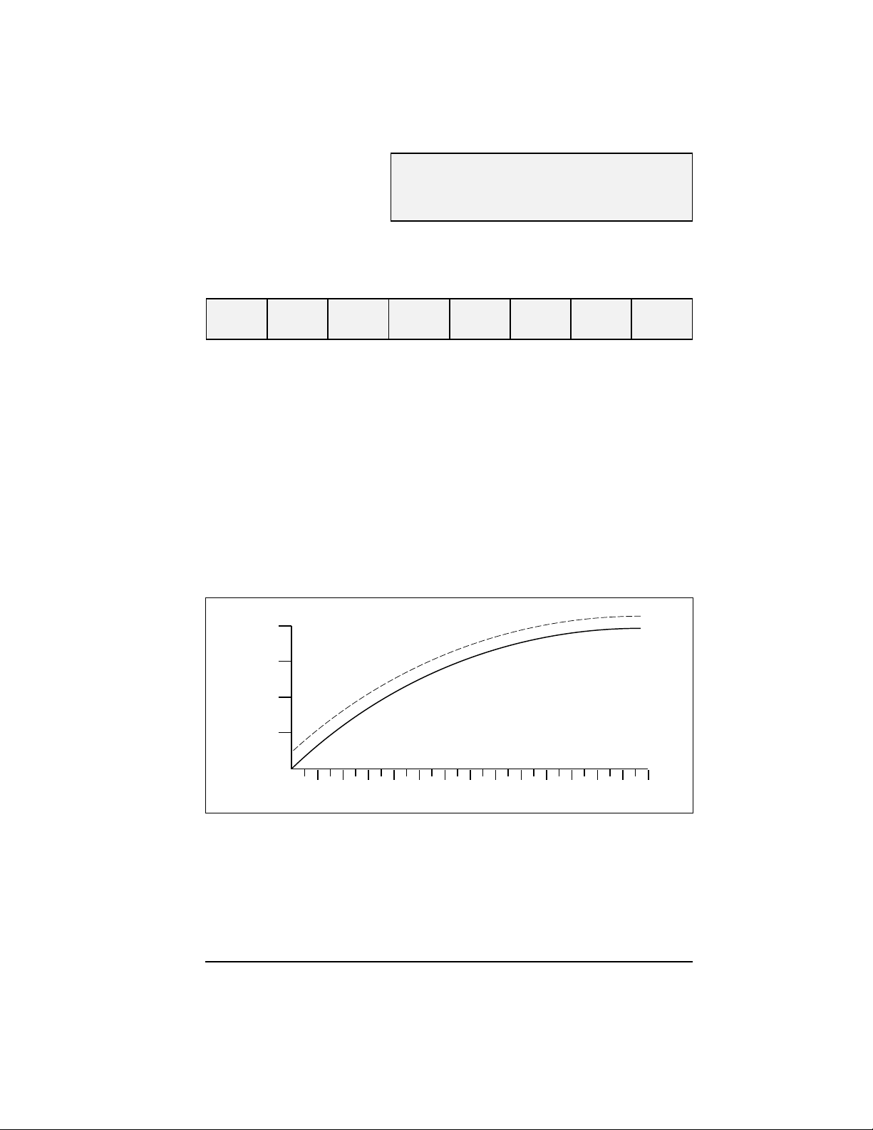
For speed steps greater than 1, the DSD will continue to sum the initial starting voltage level into
the throttle computations which has the effect of offsetting all points on a given speed curve by
the level set by Vstart as illustrated in the figure below.
❐■
■❐
Register Mode Ops Mode Shor t Form
■■
Paged Mode Ops Mode Long Form
CV2
255
VSTART = 20
100%
VSTART = 0
75%
50%
25%
MOTOR VOLTAGE
0%
0 2 4 6 8 10 12 14 16 18 20 22 24 26 28
SPEED STEP
Default value:07
LC SERIES DIGITAL SOUND DECODER TECHNICAL REFERENCE 7

CV 3
Address Mode Direct Mode
BASELINE
ACCELERATION RATE
Description
Contains a value between 0 and 255 (0 - 0xFF) that sets the decoder’s acceleration rate:
bit 7 bit 0
D7 D6 D5 D4 D3 D2 D1 D0
D0-D7: Baseline Acceleration Rate
Acceleration rate may be computed as:
seconds/speed step = ————————————
❐■
■❐
Register Mode Ops Mode Shor t Form
■■
Paged Mode Ops Mode Long Form
CV 3 * 0.896
Number of Speed Steps
When this CV is set to 0, the locomotive speed will respond nearly instantly to
throttle setting. When set to 255, it will take approximately 3.8 minutes to accelerate to full speed
from a standing stop.
It is recommended that this CV be set to a nonzero value when operating the DSD in 14 or 28
speed step modes as the throttle will interpolate between speed steps during acceleration to
produce a smoother overall response. The Dynamic Digital Exhaust sound effect will also be more
prevalent with higher acceleration settings.
increases
in the
Default value:0
Related CVs: See also Baseline Braking Rate, Consist Acceleration Rate,
8 LC SERIES DIGITAL SOUND DECODER TECHNICAL REFERENCE
Consist Brake Rate.

CV 4
Address Mode Direct Mode
BASELINE
BRAKING RA TE
Description
Contains a value between 0 and 255 (0 - 0xFF) that sets the decoder’s braking rate:
bit 7 bit 0
D7 D6 D5 D4 D3 D2 D1 D0
D0-D7: Baseline Braking Rate
Braking rate may be computed as:
seconds/speed step = —————————————
❐■
■❐
Register Mode Ops Mode Shor t Form
■■
Paged Mode Ops Mode Long Form
CV 4 * 0.896
Number of Speed Steps
When this CV is set to 0, the locomotive speed will respond nearly instantly to
throttle setting. When set to 255, it will take approximately 3.8 minutes to brake to a stop from full
speed.
It is recommended that this CV be set to a nonzero value when operating the DSD in 14 or 28
speed step modes as the throttle will interpolate between speed steps during braking to produce
a smoother overall response. The Dynamic Digital Exhaust sound effect will also be more prevalent with higher braking rates.
decreases
in the
Default value:0
Related CVs: See also Baseline Acceleration, Consist Acceleration Rate,
LC SERIES DIGITAL SOUND DECODER TECHNICAL REFERENCE 9
Consist Brake Rate.

CV 7
Address Mode Direct Mode
MANUFACTURER
VERSION ID (Read Only)
Description
Contains 8 bit software version identifier.
bit 7 bit 0
D7 D6 D5 D4 D3 D2 D1 D0
D0-D7: Version Code
32 = DSD-100LC Steam, V2.0
33 = DSD-B280LC, DSD-B3TSLC, V2.0
34 = DSD-100LC Diesel, V2.0
35 = DSD-AT100LC, DSD-LL110LC, DSD-KT100LC, V2.0
36 = DSD-LL100LC, V2.0
37 = DSD-C628LC, V2.0
This CV is read only and cannot be modified.
❐■
❐❐
Register Mode Ops Mode Shor t Form
■■
Paged Mode Ops Mode Long Form
10 LC SERIES DIGITAL SOUND DECODER TECHNICAL REFERENCE

CV 8
Address Mode Direct Mode
MANUF ACTURER ID
Description
Contains the NMRA issued Manufacturer ID code assignment (141) for SoundTraxx/Throttle Up!:
bit 7 bit 0
100011 01
Writing a value of 8 to this CV will reset all CVs to their default value. All other write operations will
be ignored.
❐■
❐❐
Register Mode Ops Mode Shor t Form
■■
Paged Mode Ops Mode Long Form
LC SERIES DIGITAL SOUND DECODER TECHNICAL REFERENCE 11

CV 9
Address Mode Direct Mode
PWM PERIOD
Description
Determines the PWM period of the motor drive signals:
bit 7 bit 0
D7 D6 D5 D4 D3 D2 D1 D0
D0-D7: PWM Period
The motor PWM period in milliseconds is computed as:
Period = (255 - CV9) * 0.2408
This CV may be programmed with any value between 0 and 230 corresponding to a PWM period
range of 52.2mS to 5.12mS. The motor drive frequency can be found by taking the reciprocal of
the period. The drive frequency can thus be programmed from 19.1 Hz to 195 Hz.
The decoder will ignore commands that attempt to program this register with values greater than
230.
The correct value for this register will vary depending upon the locomotive the DSD is installed in
and it may take some experimentation to find the optimal value. Generally, the selected value will
require a trade-off decision between motor torque and audible noise. Lower numbers will produce
more torque but may cause the motor and driveline to resonate and buzz loudly. On smaller
engines that lack traction, sufficient torque can be produced to cause the drive wheels to slip.
Higher numbers, on the other hand, will tend to reduce the buzzing noise but there may be some
loss in power, especially at low speeds. The following values are provided as a guide line to help
establish a starting point for determining the best PWM period value:
❐■
❐❐
Register Mode Ops Mode Shor t Form
■■
Paged Mode Ops Mode Long Form
Scale CV9 Value
N, HOn3 180-200
HO, S 175-185
O 160-175
G 120-160
Note: CV 9 also affects the modulation period of the Hyperlight eff ects . When using the Hyperlight
effects, it is recommended that CV 9 be programmed with v alues greater than 155 as an anno ying
flicker may otherwise result.
Default Value: 180, Corresponds to 65Hz drive frequency.
12 LC SERIES DIGITAL SOUND DECODER TECHNICAL REFERENCE

CV 11
Address Mode Direct Mode
P ACKET TIME OUT
VALUE
Description
Contains a value between 0 and 255 corresponding to the time period that is allowed to elapse
between receipt of a valid packet addressed to the DSD before a throttle shutdown occurs.
bit 7 bit 0
D7 D6 D5 D4 D3 D2 D1 D0
D0-D7: Packet Time-out Value
The time out period is computed in seconds as:
Time Out Period = CV11 X 10
A CV value of 0 disables the time out period and the locomotive will run indefinitely without receiving another packet.
For all other values, the DSD maintains an internal timer which is reset every time the DSD receives a valid broadcast address packet or other valid packet whose address matches its primary
address or, if enabled, the extended address or consist address.
In the event no valid pac k ets are received within the prescribed time period, the DSD will bring the
locomotive to a stop at the rate set by CV 4 and CV 24. The state of the auxiliary function outputs
will remain unchanged.
❐■
❐❐
Register Mode Ops Mode Shor t Form
■■
Paged Mode Ops Mode Long Form
Default value:00
LC SERIES DIGITAL SOUND DECODER TECHNICAL REFERENCE 13

CV 17,18
Address Mode Direct Mode
EXTENDED
ADDRESS
Description
CV 17 and 18 make up a ‘paired’ CV, meaning that the two CV registers taken together hold one
piece of data, in this case, the 14 bit extended decoder address:
CV 17 Extended Address MSB
bit 7 bit 0
A15 A14 A13 A12 A11 A10 A09 A08
CV 18 Extended Address LSB
bit 7 bit 0
A7 A6 A5 A4 A3 A2 A1 A0
A0-A15: Extended Address Value
The extended address allows the decoder to be assigned one of 10,179 addresses ranging from
0xC000 to 0xE7FF (Note however, that most command stations will only recognize addresses
0000 through 9999.). The extended address will only be recognized by the decoder when CV 29,
bit 5 is set to 1. Once this bit is set, the decoder will no longer recognize its primary address until
CV 29, bit 5 is cleared.
❐■
❐❐
Register Mode Ops Mode Shor t Form
■■
Paged Mode Ops Mode Long Form
CV 17 contains the most significant byte and must be loaded with values within the range of 0xC0
and 0xE7. CV 18 contains the least significant byte and may contain any value.
T o determine the extended address v alue, add the desired f our digit address to the number 49152.
Divide this number by 256 and record the quotient and the remainder. CV 17 is then programmed
with the quotient value and CV 18 is programmed with the remainder value.
Example: Compute CV 17 and 18 register values for extended address 7152.
1. Add 7152 to 49152: Sum = 56304.
2. Divide 56304 by 256: Quotient = 219 Remainder = 240
3. Program CV 17 to 219 (0xDB)
4. Program CV 18 to 240 (0xF0)
Note: Most command stations will handle these computations automatically when setting the extended address. However, it’s still nice to know how to derive them.
Because CV 17 and 18 make up a paired CV, programming order is important. CV 17 must be
written to first, followed by a write to CV 18. The decoder will ignore commands that attempt to
program these register out of order or with values outside the allowed range of 0xC000 to 0xE7FF
These CVs may be changed in operations mode only when CV 29, bit 5 is cleared (i.e., CV 1,
Primary Address is enabled).
Default Value: 0xC000 (Long Address 0003)
Related CVs: See also Primary Address, CV 29, Consist Address.
14 LC SERIES DIGITAL SOUND DECODER TECHNICAL REFERENCE

CV 19
Address Mode Direct Mode
CONSIST ADDRESS
Description
Contains address and direction data for consist operation:
bit 7 bit 0
CDIR A6 A5 A4 A3 A2 A1 A0
Bit 0-6: A0-A6, Consist Address Value
Bit 7: CDIR, Consist Direction
0 = Normal Direction
1 = Reverse Direction
The CDIR bit defines orientation of the locomotive within a consist and specifies whether the
direction bit in a speed/direction data packet should be inverted.
Bits A0-A6 assigns the consist address from 0 to 127 (0-0x7F).
If A0-A6 = 00, consist commands are ignored. Otherwise, if the decoder receives a valid com-
mand packet whose address matches the consist address, the packet will be processed as any
other packet with the following exceptions:
Long Form CV Access instructions will be ignored.
The direction bit in a speed/direction or advanced operation packet is
inverted if CDIR = 1.
❐■
❐❐
Register Mode Ops Mode Shor t Form
■■
Paged Mode Ops Mode Long Form
Only the auxiliary functions enabled in CV 21 and CV 22 are allowed to change.
When the consist address is active, speed/direction and advanced operations packets
sent to the decoder’s primary address (or extended address, if enabled) will be ignored.
All other instruction packets sent to the decoder’s primary (or extended) address includ-
ing CV access and function control will continue to be processed as normal.
In summary, setting CV 19 to 00 or 128 (0x80) disables consist addressing. Setting CV to a value
between 1 and 127 (0x01-0x7F) enables consist addresses 1 to 127 (0x01-0x7F) with the locomotive oriented facing
enables consist addresses 1 to 127 with the locomotive oriented facing
Default Value:00
Related CVs: See also Primary Address, Consist Function Active,
LC SERIES DIGITAL SOUND DECODER TECHNICAL REFERENCE 15
forward
in the consist. Setting CV to a v alue between 129 and 255 (0x81-0xFF)
backwards
Consist FL Function Active.
in the consist.

CV 21
Address Mode Direct Mode
CONSIST FUNCTION
ACTIVE
Description
Defines which functions may be controlled by packets sent to the decoder’s consist address.
Disabled functions may be controlled only from decoder’s primary or extended address:
bit 7 bit 0
F8 F7 F6 F5 F4 F3 F2 F1
Bit 0: F1, Consist Function 1 Enable Bit
0 = function is disabled for consist operation.
1 = function is enabled for consist operation.
❐■
❐❐
Register Mode Ops Mode Shor t Form
■■
Paged Mode Ops Mode Long Form
Bit 1: F2, Consist Function 2 Enable Bit
Bit 2: F3, Consist Function 3 Enable Bit
Bit 3: F4, Consist Function 4 Enable Bit
Bit 4: F5, Consist Function 5 Enable Bit
Bit 5: F6, Consist Function 6 Enable Bit
Bit 6: F7, Consist Function 7 Enable Bit
Bit 7: F8, Consist Function 8 Enable Bit
This register is useful for differentiating the lead engine in the consist from the other engines. For
example, by setting this register in the lead locomotive to 02 and the same register in all other
engines to 00, only the whistle on the lead locomotive will blow when the command to turn on
Function 2 is sent to the consist.
0 = function is disabled for consist operation.
1 = function is enabled for consist operation.
0 = function is disabled for consist operation.
1 = function is enabled for consist operation.
0 = function is disabled for consist operation.
1 = function is enabled for consist operation.
0 = function is disabled for consist operation.
1 = function is enabled for consist operation.
0 = function is disabled for consist operation.
1 = function is enabled for consist operation.
0 = function is disabled for consist operation.
1 = function is enabled for consist operation.
0 = function is disabled for consist operation.
1 = function is enabled for consist operation.
Default Value:00
Related CVs: See also Consist Address, Consist FL Function Active.
16 LC SERIES DIGITAL SOUND DECODER TECHNICAL REFERENCE

CV 22
Address Mode Direct Mode
CONSIST F0
FUNCTION ACTIVE
Description
Defines whether the F0 function may be controlled by packets sent to the decoder’s consist address. Disabled functions may be controlled only from decoder’s primary or extended address:
bit 7 bit 0
0 0 0 0 0 0 F0(r) F0(f)
❐■
❐❐
Register Mode Ops Mode Shor t Form
■■
Paged Mode Ops Mode Long Form
Bit 0: F0(f), F0 Forward enable Bit
Bit 1: F0(r), F0 Reverse enable Bit
This register is useful for differentiating the Headlight and Backup Light functions in the lead
engine of the consist from the other engines. For example, by setting this register in the lead
locomotive to 01 and the same register in all other engines to 00, only the headlight in the lead
engine will be on and only when the consist is moving forward.
0 = function is disabled for consist operation.
1 = function is enabled for consist operation.
0 = function is disabled for consist operation.
1 = function is enabled for consist operation.
Default Value:00
Related CVs: See also Consist Address, Consist Function Active.
LC SERIES DIGITAL SOUND DECODER TECHNICAL REFERENCE 17

CV 23
Address Mode Direct Mode
CONSIST
ACCELERATION RATE
Description
Contains a value between -127 to +127 corresponding to the decoder’s consist acceleration off-
set:
bit 7 bit 0
sign D6 D5 D4 D3 D2 D1 D0
Bits 0-6: D0-D6, Consist Acceleration value
Bit 7: Sign
0 = positive value
1 = negative value
When the consist address is active, the consist acceleration rate is added to or subtracted from
the decoder’s base acceleration rate depending on the sign bit. The acceleration is then computed
as:
seconds/speed step = —————————————
If the sum of CV 3 and CV 23 is negative, then the acceleration rate is set to 0 (i.e., acceleration
is instant.) If the sum of CV 3 and CV 23 exceeds 255, then the acceleration rate is set to the
maximum value of 255.
❐■
❐■
Register Mode Ops Mode Shor t Form
■■
Paged Mode Ops Mode Long Form
(CV3 + CV 23) * 0.896
Number of Speed Steps
This CV has no effect when the consist address is set to 0.
In summary, a CV value between 0 and 127 (0x7F) will
rate. Values between 128 (0x80) and 255 (0xFF) will
rate.
Default value:0
Related CVs: See also Baseline Acceleration Rate, Baseline Braking Rate,
Consist Brake Rate.
18 LC SERIES DIGITAL SOUND DECODER TECHNICAL REFERENCE
increase
decrease
the decoder’s base acceleration
the decoder’s base acceleration
 Loading...