

Page 1

Scope
This section of the manual is designed to provide the advanced user with additional insight into the operation and
capabilities of the SoundTraxx Digital Sound Decoder . By necessity, it is somewhat technical in nature and assumes
a working knowledge of the NMRA DCC Standards and RPs as well as a familiarity with binary and hexadecimal
number systems.
The novice user should not be dissuaded from studying this section as it will help add to his knowledge of DCC
technology and enable him to take greater advantage of its capabilities.
Copies of the NMRA DCC Standards and Recommended Practices may be obtained by contacting:
Technical Department
NMRA Headquarters
4121 Cromwell Road
Chattanooga, TN 37421 USA
Phone: (615) 892-2846
As always, our Technical Support staff will be happy to answer any specific questions you may have regarding the
SoundTraxx DSD.
Applicable Standards
The SoundTraxx DSD has been designed to meet the requirements of the following NMRA Standards and RPs as
defined by September, 1996:
Standard S-9.1 DCC Electrical Standard
Standard S-9.2 DCC Communication Standard
RP-9.1.1 Electrical Interface and Wire Color Code
RP-9.2.1 DCC Extended Packet Format
RP-9.2.2 DCC Configuration Variable
RP-9.2.3 (Tentative) DCC Service Mode
RP-9.2.4 DCC Fail-Safe Operating Characteristics
Bit Timing
The DSD uses a quartz cr ystal timing reference and will recognize DCC packet bits that fall within the following
timing constraints: “1” Bit, 52µS to 64µS
“0” Bit, 90µS to 12000µS
Packets containing bits that fall outside of this range will be rejected.
Addressing Modes
The DSD recognizes the following address modes and ranges as defined by RP-9.2.1:
Broadcast Address 00
Decoder Addresses 01-127
Consist Addresses 01-127
Extended Addresses 0xC000 - 0xE7FF
Packets contain addresses outside of these ranges will be ignored.
Command Instructions
The DSD will process valid packets containing the following instruction codes as defined by RP-9.2.1:
000 Decoder and Consist Control
All currently defined forms of this instruction are processed except 00000110b, Set Advanced Acknowledgment. This instruction is ignored.
Digital Sound Decoder Technical Reference
1
Page 2

001 Advanced Operation Instructions
The DSD will process only the 128 Speed Step Control form (00111111b) of this instruction.
All other sub-instructions will be ignored.
010 Reverse Speed and Direction Instruction
The DSD will process all forms of this instruction.
011 Forward Speed and Direction Instruction
The DSD will process all forms of this instruction.
100 Function Group One
The DSD will process all forms of this instruction.
101 Function Group two
The DSD will process all forms of this instruction.
110 Reserved Instruction
The DSD will process all forms of this instruction.
111 Configuration Variable Access
The DSD will parse both the short form and long form of this instruction.
Only short form instructions formatted as 11110010b (CV 23 access) or 11110011b (CV 24 access) will be processed. All other short form instruction will be ignored.
All long form instructions will be processed. Ho wever, attempts to write to the following CVs in operations mode will
be ignored:
CV 1 Primary Address
CV 7 Mfg. Version ID
CV 8 Mfg. ID
CV 17 Extended Address MSB
CV 18 Extended Address LSB
Write operations to other CVs may be ignored if an attempt is made to write illegal values. See individual CV
descriptions for details on illegal values.
The DSD will send a basic acknowledgment upon successfully processing an operations mode CV access instruction provided the locomotive is stopped. Otherwise, no acknowledgment is sent.
Programming Modes
The DSD will supports all six programming modes defined in RP-9.2.1 and RP-9.2.3:
Address Mode
Register Mode
Service Mode
Direct Mode
Ops Mode Long Form
Ops Mode Short Form
Not all CVs can be programmed using all modes. Table A lists all CVs supported by the DSD, their applicable
programming mode address as well as the factory default values.
When entering service mode, the DSD will turn off all auxiliary functions and sounds to reduce its current draw to as
low a level as possible.
If the DSD receives an instruction packet to read or write a CV not listed in Table A, the instruction packet will be
ignored and no acknowledgment will be generated.
2
Digital Sound Decoder Technical Reference
Page 3

Upon completion of a paged mode operation, the DSD will reset the page register to 01.
The address query instruction is
not
supported by the DSD.
Miscellaneous Operating Notes
Consist operation is enabled whenev er the consist address (CV 19, bits 0:6) is loaded with a non-zero v alue . Per the
NMRA standard, when the consist address is enabled, the DSD will no longer parse speed/direction pack ets sent to
its primary address. Additionally, the DSD will ignore long form CV access instructions sent to its consist address.
Because the DSD instruction parser assigns a higher priority to the consist address, this can cause unexpected
behavior under certain conditions:
When the DSD is set up for 14 speed step mode with the consist address active, the DSD outputs will no longer
respond to FL function commands sent to the primary address. This may be remedied by using a different speed
step mode or enabling FL consist functions (see CV 22).
If the consist address is set to the same value as the primary address, the DSD will no longer process long form
operations mode CV access instructions sent to the primary address. As a result, the user will be required to use
service mode CV access instructions to clear the consist address. If the extended address is enabled (see CV 29),
this will not be a problem.
Analog Mode Operation
The DSD does
not
support Analog Mode operation and will remain inoperative when placed on a conventional DC
track.
CVs Support
The following table lists all CVs used by the DSD. Details regarding each CV can be found on subsequent pages.
Table A.
CVs Used by the Digital Sound Decoder
Program Mode Address
CV# Name Default Direct Register Paged Mode
Value Mode Mode Page:Register
1 Primary Address 3 01 (0x01) 0 1:0
2 Vstart 7 02 (0x02) 1 1:1
3 Acceleration Rate 0 03 (0x03) 2 1:2
4 Braking Rate 0 04 (0x04) 3 1:3
7 Version ID 06 07 (0x07) 6 2:3
8 Manufacturer ID 141 (0x8D) 08 (0x08) 7 3:0
9 Motor PWM Period 180 (0xB4) 09 (0x09) 3:1
11 Time Out Period 0 11 (0x0B) 3:3
17 Extended Address MSB 192 (0xC0) 17 (0x11) 5:1
18 Extended Address LSB 03 18 (0x12) 5:2
19 Consist Address 0 19 (0x13) 5:3
21 Consist Func. Active 0 21 (0x15) 6:1
22 Consist FL Active 0 22 (0x16) 6:2
23 Consist Acceleration 0 23 (0x17) 6:3
24 Consist Deceleration 0 24 (0x18) 7:0
25 Speed Table Select 0 25 (0x19) 7:1
29 Configuration Data #1 02 29 (0x1D) 4 8:1
30 Error Information 0 30 (0x1E) 8:2
33 FL(f) Output Location 1 33 (0x21) 9:1
(Note 1)
Digital Sound Decoder Technical Reference
3
Page 4

CV# Name Default Direct Register Paged Mode
Value Mode Mode Page:Register
34 FL(r) Output Location 2 34 (0x22) 9:2
35 F1 Output Location 4 35 (0x23) 9:3
36 F2 Output Location 8 36 (0x24) 10:0
37 F3 Output Location 2 37 (0x25) 10:1
38 F4 Output Location 4 38 (0x26) 10:2
39 F5 Output Location 8 39 (0x27) 10:3
40 F6 Output Location 16 (0x10) 40 (0x28) 11:0
41 F7 Output Location 4 41 (0x29) 11:1
42 F8 Output Location 128 (0x80) 42 (0x2A) 11:2
49 Hyperlight Config. 0 49 (0x31) 13:1
50 Sound V olume 8 50 (0x32) 13:2
51 Background Snd Config 190 (0xBE) 51 (0x33) 13:3
52 Foreground Snd Config 70 (0x46) 52 (0x34) 14:0
53 Snd Config. Byte #3 0 53 (0x35) 14:1
54 Auto Exhaust Rate 94 (0x5E) 54 (0x36) 14:2
55 Exhaust Tone 08 55 (0x37) 14:3
56 Exhaust V olume 255 (0xFF) 55 (0x38) 15:0
66 Forward Trim 128 (0x80) 66 (0x42) 17:1
67 Speed Step 1 0 (0x00) 67 (0x43) 17:2
68 Speed Step 2 9 (0x09) 68 (0x44) 17:3
69 Speed Step 3 18 (0x12) 69 (0x45) 18:0
70 Speed Step 4 28 (0x1C) 70 (0x46) 18:1
71 Speed Step 5 37 (0x25) 71 (0x47) 18:2
72 Speed Step 6 47 (0x2F) 72 (0x48) 18:3
73 Speed Step 7 56 (0x38) 73 (0x49) 19:0
74 Speed Step 8 66 (0x42) 74 (0x4A) 19:1
75 Speed Step 9 75 (0x4B) 75 (0x4B) 19:2
76 Speed Step 10 85 (0x55) 76 (0x4C) 19:3
77 Speed Step 11 94 (0x5E) 77 (0x4D) 20:0
78 Speed Step 12 103 (0x67) 78 (0x4E) 20:1
79 Speed Step 13 113 (0x71) 79 (0x4F) 20:2
80 Speed Step 14 122 (0x7A) 80 (0x50) 20:3
81 Speed Step 15 132 (0x84) 81 (0x51) 21:0
82 Speed Step 16 141 (0x8D) 82 (0x52) 21:1
83 Speed Step 17 151 (0x97) 83 (0x53) 21:2
84 Speed Step 18 160 (0xA0) 84 (0x54) 21:3
85 Speed Step 19 170 (0xAA) 85 (0x55) 22:0
86 Speed Step 20 179 (0xB3) 86 (0x56) 22:1
87 Speed Step 21 188 (0xBC) 87 (0x57) 22:2
88 Speed Step 22 198 (0xC6) 88 (0x58) 22:3
89 Speed Step 23 207 (0xCF) 89 (0x59) 23:0
90 Speed Step 24 217 (0xD9) 90 (0x5A) 23:1
91 Speed Step 25 226 (0xE2) 91 (0x5B) 23:2
92 Speed Step 26 236 (0xEC) 92 (0x5C) 23:3
93 Speed Step 27 245 (0xF5) 93 (0x5D) 24:0
94 Speed Step 28 255 (0xFF) 94 (0x5E) 24:1
95 Reverse Trim 128 (0x80) 95 (0x5F) 24:2
105 User Indentifier #1 0 105 (0x69) 27:1
106 User Indentifier #2 0 106 (0x6A) 27:2
Register Mode Ops Mode Short Form
Paged Mode Ops Mode Long Form
Address Mode Direct Mode
Program Mode Address
(Note 1)
Note1: Paged mode address is shown as PP:RR where PP is the page number and RR is the data register 0-3.
4
Digital Sound Decoder Technical Reference
Page 5

Address Mode Direct Mode
CV 1
PRIMARY ADDRESS
■■
Register Mode Ops Mode Shor t Form
■❐
Paged Mode Ops Mode Long Form
■❐
CONTROL
Description
Contains the decoder’s primary address between 1 and 127:
bit 7 bit 0
0 A6A5A4A3A2A1A0
Bit 0-6: A0-A6, Decoder Address
Bit 7: Not used. Must be set to 0!
The decoder will process all valid instruction packets containing an address that matches the
value contained in this register when CV 29, bit 5 is set to 0.
Programming this register with a new value will automatically clear the Consist Address (CV 19)
to 0 and clear the Extended Address Enable bit in CV 29 (bit 5).
The decoder will ignore commands that attempt to program this register with values outside the
range of 1 to 127.
Note that this CV cannot be changed in operations mode.
Default V alue:03
Related CVs: See also CV 29, Consist Address, Extended Address
Digital Sound Decoder Technical Reference
5
Page 6
❐■
CV 2
VSTART
Description
Vstart defines the initial voltage level applied to the motor at speed step 1 as a fraction of
available supply voltage:
bit 7 bit 0
D7 D6 D5 D4 D3 D2 D1 D0
D0-D7: Motor Start Voltage
Vstart may contain any value from 0 to 255 (0 - 0xFF).
The starting voltage applied to the motor may be computed as:
Address Mode Direct Mode
■❐
Register Mode Ops Mode Short Form
■■
Paged Mode Ops Mode Long Form
Starting Voltage = Supply Voltage X ——
where CV 2 is the contents of the Vstart register. A value of 0 corresponds to a zero starting
voltage and 255 corresponds to the maximum available voltage.
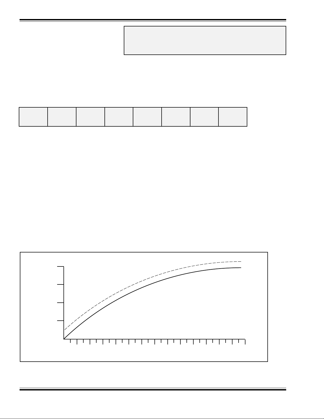
For speed steps greater than 1, the DSD will continue to sum the initial starting voltage level
into the throttle computations which has the effect of offsetting all points on a given speed
curve by the level set by Vstar t as illustrated in the figure below.
100%
75%
50%
25%
MOTOR VOLTAGE
0%
CV2
255
VSTART = 20
VSTART = 0
0 2 4 6 8 10 12 14 16 18 20 22 24 26 28
Default value:07
6
SPEED STEP
Digital Sound Decoder Technical Reference
Page 7

Address Mode Direct Mode
CV 3
BASELINE
❐■
Register Mode Ops Mode Shor t Form
■❐
Paged Mode Ops Mode Long Form
■■
ACCELERATION
RATE
Description
Contains a value between 0 and 255 (0 - 0xFF) that sets the decoder’s acceleration rate:
bit 7 bit 0
D7 D6 D5 D4 D3 D2 D1 D0
D0-D7: Baseline Acceleration Rate
Acceleration rate may be computed as:
seconds/speed step = ———————————
Number of Speed Steps
When this CV is set to 0, the locomotive speed will respond nearly instantly to
throttle setting. When set to 255, it will take approximately 3.8 minutes to acceler ate to full speed
from a standing stop.
It is recommended that this CV be set to a nonzero value when operating the DSD in 14 or 28
speed step modes as the throttle will interpolate between speed steps during acceleration to
produce a smoother overall response. The Dynamic Digital Exhaust sound effect will also be
more prevalent with higher acceleration settings.
CV 3 * 0.896
increases
in the
Default value:0
Related CVs: See also Baseline Braking Rate, Consist Acceleration Rate,
Consist Brake Rate.
Digital Sound Decoder Technical Reference
7
Page 8

CV 4
BASELINE
Address Mode Direct Mode
❐■
Register Mode Ops Mode Short Form
■❐
Paged Mode Ops Mode Long Form
■■
BRAKING RATE
Description
Contains a value between 0 and 255 (0 - 0xFF) that sets the decoder’s braking rate:
bit 7 bit 0
D7 D6 D5 D4 D3 D2 D1 D0
D0-D7: Baseline Braking Rate
Braking rate may be computed as:
seconds/speed step = ———————————
Number of Speed Steps
When this CV is set to 0, the locomotive speed will respond nearly instantly to
throttle setting. When set to 255, it will tak e appro ximately 3.8 min utes to brak e to a stop from full
speed.
It is recommended that this CV be set to a nonzero value when operating the DSD in 14 or 28
speed step modes as the throttle will interpolate between speed steps during braking to produce
a smoother over all response. The Dynamic Digital Exhaust sound eff ect will also be more pre v alent with higher braking rates.
CV 4 * 0.896
decreases
in the
Default value:0
Related CVs: See also Baseline Acceleration, Consist Acceleration Rate,
Consist Brake Rate.
8
Digital Sound Decoder Technical Reference
Page 9

Address Mode Direct Mode
CV 7
MANUFACTURER
❐■
Register Mode Ops Mode Shor t Form
■❐
Paged Mode Ops Mode Long Form
■■
VERSION ID (Read Only)
Description
Contains 8 bit software version identifier.
bit 7 bit 0
D7 D6 D5 D4 D3 D2 D1 D0
D0-D7: Version Code
06 = DSD-050 Steam Decoder, Release 1.2
07 = DSD-150 Steam Decoder, Release 1.2
09 = DSD-150 Diesel Decoder, Release 1.0
11 = DSD-150 Diesel Decoder, Release 1.1
14 = DSD-150 Diesel Decoder, Release 1.2
This CV is read only and cannot be modified.
Digital Sound Decoder Technical Reference
9
Page 10

Address Mode Direct Mode
CV 8
MANUFACTURER ID
(Read Only)
Description
Contains the NMRA issued Manufacturer ID code assignment
for Throttle Up!:
bit 7 bit 0
100011 01
This value is read only and fixed at 141 (0x8D).
❐■
Register Mode Ops Mode Short Form
■❐
Paged Mode Ops Mode Long Form
■■
10
Digital Sound Decoder Technical Reference
Page 11

Address Mode Direct Mode
CV 9
PWM PERIOD
Description
Determines the PWM period of the motor dr ive signals:
bit 7 bit 0
D7 D6 D5 D4 D3 D2 D1 D0
D0-D7: PWM Period
The motor PWM period in microseconds is computed as:
Period = (255 - CV9) * 204.8
This CV may be programmed with an y v alue between 0 and 230 corresponding to a PWM period
range of 52.2µS to 5.12µS. The motor drive frequency can be found by taking the reciprocal of
the period. The drive frequency can thus be programmed from 19.1 Hz to 195 Hz.
❐■
Register Mode Ops Mode Shor t Form
❐❐
Paged Mode Ops Mode Long Form
■■
The decoder will ignore commands that attempt to program this register with v alues greater than
230.
The correct value f or this register will v ary depending upon the locomotive the DSD is installed in
and it may tak e some e xperimentation to find the optimal value . Generally, the selected value will
require a trade-off decision between motor torque and audible noise. Lower numbers will produce more torque but ma y cause the motor and driveline to resonate and b uzz loudly. On smaller
engines that lack traction, sufficient torque can be produced to cause the drive wheels to slip.
Higher numbers, on the other hand, will tend to reduce the buzzing noise b ut there ma y be some
loss in power, especially at low speeds. The following values are provided as a guide line to help
establish a starting point for determining the best PWM period value:
Scale CV9 Value
N, HOn3 180-200
HO, S 175-185
O 160-175
G 120-160
Note: CV 9 also affects the modulation period of the Hyperlight effects. When using the Hyperlight effects, it is recommended that CV 9 be programmed with values greater than 155 as an annoying flicker
may otherwise result.
Default V alue:180 (0xB4), Corresponds to 65Hz dr ive frequency.
Digital Sound Decoder Technical Reference
11
Page 12

❐■
CV 11
P ACKET TIME OUT
Address Mode Direct Mode
❐❐
Register Mode Ops Mode Short Form
■■
Paged Mode Ops Mode Long Form
VALUE
Description
Contains a value between 0 and 255 corresponding to the time period that is allowed to elapse
between receipt of a valid packet addressed to the DSD before a throttle shutdown occurs.
bit 7 bit 0
D7 D6 D5 D4 D3 D2 D1 D0
D0-D7: Pack et Time-out Value
The time out period is computed in seconds as:
Time Out Period = CV11 X 10
A CV value of 0 disables the time out period and the locomotive will run indefinitely without
receiving another packet.
For all other values, the DSD maintains an internal timer which is reset every time the DSD
receives a valid broadcast address packet or other valid packet whose address matches its
primary address or, if enabled, the extended address or consist address.
In the event no valid packets are received within the prescribed time period, the DSD will br ing
the locomotive to a stop at the rate set by CV 4 and CV 24. The state of the auxiliary function
outputs will remain unchanged.
Default value:00
12
Digital Sound Decoder Technical Reference
Page 13

Address Mode Direct Mode
CV 17,18
EXTENDED
❐■
Register Mode Ops Mode Shor t Form
❐❐
Paged Mode Ops Mode Long Form
■❐
ADDRESS
Description
CV 17 and 18 make up a ‘paired’ CV, meaning that the two CV registers taken together hold one piece of
data, in this case, the 14 bit extended decoder address:
CV 17 Extended Address MSB
bit 7 bit 0
A15 A14 A13 A12 A11 A10 A09 A08
CV 18 Extended Address LSB
bit 7 bit 0
A7 A6 A5 A4 A3 A2 A1 A0
A0-A15: Extended Address Value
The extended address allows the decoder to be assigned one of 10,179 addresses r anging from 0xC000 to 0xE7FF
(Note however, that most command stations will only recognize addresses 0000 through 9999.). The extended
address will only be recognized by the decoder when CV 29, bit 5 is set to 1. Once this bit is set, the decoder will no
longer recognize its primary address until CV 29, bit 5 is cleared.
CV 17 contains the most significant byte and must be loaded with v alues within the range of 0xC0 and 0xE7. CV 18
contains the least significant byte and may contain any value.
To determine the extended address value, add the desired four digit address to the number 49152. Divide this
number by 256 and record the quotient and the remainder . CV 17 is then programmed with the quotient v alue and CV
18 is programmed with the remainder value .
Example: Compute CV 17 and 18 register values for extended address 7152.
Note: Most command stations will handle these computations automatically when setting the extended address.
However, it’s still nice to know how to derive them.
Because CV 17 and 18 make up a paired CV, programming order is important. CV 17 m ust be written to first, followed
by a write CV 18. The decoder will ignore commands that attempt to program these register out of order or with
values outside the allowed range of 0xC000 to 0XE7FF
1. Add 7152 to 49152: Sum = 56304.
2. Divide 56304 by 256: Quotient = 219 Remainder = 240
3. Program CV 17 to 219 (0xDB)
4. Program CV 18 to 240 (0xF0)
Note that these CVs cannot be changed in operations mode.
Default V alue: 0xC003
Related CVs: See also Primary Address, CV 29, Consist Address.
Digital Sound Decoder Technical Reference
13
Page 14

❐■
CV 19
CONSIST ADDRESS
Address Mode Direct Mode
❐❐
Register Mode Ops Mode Short Form
■■
Paged Mode Ops Mode Long Form
Description
Contains address and direction data for consist operation:
bit 7 bit 0
CDIRA6A5A4A3A2A1A0
Bit 0-6: A0-A6, Consist Address Value
Bit 7: CDIR, Consist Direction
0 = Normal Direction
1 = Reverse Direction
The CDIR bit defines orientation of the locomotive within a consist and specifies whether the direction bit
in a speed/direction data packet should be inver ted.
Bits A0-A6 assigns the consist address from 0 to 127 (0-0x7F).
If A0-A6 = 00, consist commands are ignored. Otherwise, if the decoder receives a valid command
packet whose address matches the consist address, the packet will be processed as any other packet
with the following exceptions:
Long Form CV Access instructions will be ignored.
The direction bit in a speed/direction or advanced operation packet is inverted if CDIR = 1.
Only the auxiliary functions enabled in CV 21 and CV 22 are allowed to change.
When the consist address is active, speed/direction and adv anced operations packets sent to the decoder’s
primary address (or extended address, if enabled) will be ignored. All other instruction packets sent to the
decoder’s primary (or extended) address including CV access and function control will continue to be
processed as normal.
In summary, setting CV 19 to 00 or 128 (0x80) disables consist addressing. Setting CV to a value between 1 and 127 (0x01-0x7F) enables consist addresses 1 to 127 (0x01-0x7F) with the locomotive
oriented facing
consist addresses 1 to 127 with the locomotive oriented facing
forward
in the consist. Setting CV to a value between 129 and 255 (0x81-0xFF) enables
backwards
in the consist.
Default V alue:00
Related CVs: See also Primary Address, Consist Function Active, Consist FL Function Active.
14
Digital Sound Decoder Technical Reference
Page 15

❐■
CV 21
CONSIST FUNCTION
Address Mode Direct Mode
❐❐
Register Mode Ops Mode Shor t Form
■■
Paged Mode Ops Mode Long Form
ACTIVE
Description
Defines which functions may be controlled by packets sent to the decoder’s consist address.
Disabled functions may be controlled only from decoder’s primary or extended address:
bit 7 bit 0
F8 F7 F6 F5 F4 F3 F2 F1
Bit 0: F1, Consist Function 1 Enable Bit
0 = function is disabled for consist operation.
1 = function is enabled for consist operation.
Bit 1: F2, Consist Function 2 Enable Bit
0 = function is disabled for consist operation.
1 = function is enabled for consist operation.
Bit 2: F3, Consist Function 3 Enable Bit
0 = function is disabled for consist operation.
1 = function is enabled for consist operation.
Bit 3: F4, Consist Function 4 Enable Bit
0 = function is disabled for consist operation.
1 = function is enabled for consist operation.
Bit 4: F5, Consist Function 5 Enable Bit
0 = function is disabled for consist operation.
1 = function is enabled for consist operation.
Bit 5: F6, Consist Function 6 Enable Bit
0 = function is disabled for consist operation.
1 = function is enabled for consist operation.
Bit 6: F7, Consist Function 7 Enable Bit
0 = function is disabled for consist operation.
1 = function is enabled for consist operation.
Bit 7: F8, Consist Function 8 Enable Bit
0 = function is disabled for consist operation.
1 = function is enabled for consist operation.
This register is useful for diff erentiating the lead engine in the consist from the other engines. F or e xample, by setting
this register in the lead locomotive to 02 and the same register in all other engines to 00, only the whistle on the lead
locomotive will blow when the command to turn on Function 2 is sent to the consist.
Default V alue:00
Related CVs: See also Consist Address, Consist FL Function Active.
Digital Sound Decoder Technical Reference
15
Page 16

❐■
CV 22
CONSIST FL
Address Mode Direct Mode
❐❐
Register Mode Ops Mode Short Form
■■
Paged Mode Ops Mode Long Form
FUNCTION ACTIVE
Description
Defines whether the FL function may be controlled by packets sent to the decoder’s consist
address. Disab led functions ma y be controlled only from decoder’s primary or extended address:
bit 7 bit 0
000000FL(r)FL(f)
Bit 0: FL(f), FL Forward enable Bit
0 = function is disabled for consist operation.
1 = function is enabled for consist operation.
Bit 1: FL(r), FL Reverse enable Bit
0 = function is disabled for consist operation.
1 = function is enabled for consist operation.
This register is useful for differentiating the Headlight and Backup Light functions in the lead
engine of the consist from the other engines. For example, by setting this register in the lead
locomotive to 01 and the same register in all other engines to 00, only the headlight in the lead
engine will be on and only when the consist is moving forward.
Default V alue:00
Related CVs: See also Consist Address, Consist Function Active.
16
Digital Sound Decoder Technical Reference
Page 17

❐■
CV 23
CONSIST
Address Mode Direct Mode
❐■
Register Mode Ops Mode Shor t Form
■■
Paged Mode Ops Mode Long Form
ACCELERATION
RATE
Description
Contains a value between -127 to +127 corresponding to the decoder’s consist acceleration
offset:
bit 7 bit 0
sign D6 D5 D4 D3 D2 D1 D0
Bits 0-6: D0-D6, Consist Acceleration value
Bit 7: Sign
0 = positive value
1 = negative value
When the consist address is active, the consist acceleration rate is added to or subtracted from
the decoder’s base acceleration rate depending on the sign bit. The acceleration is then com-
puted as:
seconds/speed step = ———————————
If the sum of CV 3 and CV 23 is negative, then the acceler ation r ate is set to 0 (i.e., acceleration
is instant.) If the sum of CV 3 and CV 23 exceeds 255, then the acceleration rate is set to the
maximum value of 255.
This CV has no effect when the consist address is set to 0.
In summary, a CV value between 0 and 127 (0x7F) will
rate. Values between 128 (0x80) and 255 (0xFF) will
rate.
(CV3 + CV 23) * 0.896
Number of Speed Steps
increase
decrease
the decoder’s base acceleration
the decoder’s base acceleration
Default value:0
Related CVs: See also Baseline Acceleration Rate, Baseline Braking Rate,
Consist Brake Rate.
Digital Sound Decoder Technical Reference
17
Page 18

Address Mode Direct Mode
CV 24
CONSIST
❐■
Register Mode Ops Mode Short Form
❐■
Paged Mode Ops Mode Long Form
■■
BRAKING RATE
Description
Contains a value between -127 to +127 corresponding to the decoder’s consist braking offset:
bit 7 bit 0
sign D6 D5 D4 D3 D2 D1 D0
Bits 0-6: D0-D6, Consist Braking value
Bit 7: Sign
0 = positive value
1 = negative value
When the consist address is active, the consist braking rate is added to or subtracted from the
decoder’s baseline br aking rate depending on the sign bit. The braking r ate is then computed as:
seconds/speed step = ———————————
If the sum of CV 4 and CV 24 is negative, then the br aking rate is set to 0 (i.e ., braking is instant.)
If the sum of CV 3 and CV 23 exceeds 255, then the braking rate is set to the maxim um v alue of
255.
This CV has no effect when the consist address is set to 0.
In summary , a CV v alue between 0 and 127 (0x7F) will
Values between 128 (0x80) and 255 (0xFF) will
Default value:0
(CV4 + CV 24) * 0.896
Number of Speed Steps
increase
decrease
the decoder’s base braking rate.
the decoder’s base br aking rate .
Related CVs: See also Baseline Acceleration Rate, Baseline Braking Rate,
Consist Acceleration Rate.
18
Digital Sound Decoder Technical Reference
Page 19

Address Mode Direct Mode
CV 25
SPEED T ABLE
❐■
Register Mode Ops Mode Shor t Form
❐❐
Paged Mode Ops Mode Long Form
■■
SELECT REGISTER
Description
Used to select one of 15 Speed Curves:
bit 7 bit 0
0 USER TBL3 TBL2 TBL1 TBL0
Bits 3-0: TBL3:TBL0, Preset Speed Curves Select Bits
0000 = Speed Curves not used
0001 = Speed Curves not used
0010 = Linear Speed Curve
0011 = Logarithmic Curve 1
0100 = Logarithmic Curve 2
0101 = Logarithmic Curve 3
0110 = Logarithmic Curve 4
0111 = Logarithmic Curve 5
1000 = Logarithmic Curve 6
1001 = Logarithmic Curve 7
1010 = Exponential Curve 1
1011 = Exponential Curve 2
1100 = Exponential Curve 3
1101 = Exponential Curve 4
1110 = Exponential Curve 5
1111 = Exponential Curve 6
Bit 4: USER, User Loadable Speed Table Select
0 = Enable Speed cur ve defined by TBL3:TBL0
1 = Enable Speed curve defined by CVs 67-94.
Bits 5-6: Not Used. These bits are ignored.
Bit 7: Mid Range Speed Step
This bit is not implemented and always reads as 0.
CV 25 may be progr ammed with an y v alue between 0 and 31 (0x1F). Values between 02 and 15
(0x0F) allow the user to select from one of 14 predefined speed curves as depicted below. The
logarithmic curves provide a shallower speed response as the throttle is increased. These curves
are useful for locomotiv es that require a high starting voltage to get mo ving or matching a highly
geared locomotive to one that has less gearing. The exponential curves are useful for slowing
Digital Sound Decoder Technical Reference
19
Page 20

down locomotives that have a “slot car” response.
Address Mode Direct Mode
Register Mode Ops Mode Short Form
Setting this CV to a value between 16 and 31 (0x10-0x1F) will enable the speed cur ve pro-
Paged Mode Ops Mode Long Form
grammed into CVs 67-94. This curve may modified by the user to get vir tually any response
desired.
Note that in order for the selected curve to be activ e, bit 4 of CV 29 must also be set to 1. If CV 29,
bit 4 is 0, the throttle response will be linear (straight line).
The speed curves can be used in 14, 28 and 128 speed step modes.
Bit 7 is defined by the NMRA RPs as the Mid Range Speed Step select bit. The DSD does not
implement this feature and will ignore commands that attempt to program this bit with a 1 (i.e.,
data values between 128-255 or 0x80-0xFF).
100%
LOG 7
LOG 6
75%
LOG 5
LOG 4
LOG 3
LOG 2
LOG 1
50%
25%
LINEAR
EXP 1
EXP 2
EXP 3
EXP 4
EXP 5
EXP 6
0%
0 2 4 6 8 10 12 14 16 18 20 22 24 26 28
Default value:0
Related CVs: See also CV 29, Loadable Speed Table.
20
Digital Sound Decoder Technical Reference
Page 21

Address Mode Direct Mode
CV 29
CONFIGURATION
❐■
Register Mode Ops Mode Shor t Form
■❐
Paged Mode Ops Mode Long Form
■■
REGISTER 1
Description
CV 29 contains miscellaneous decoder configuration bits:
bit 7 bit 0
0 N/A EAM STE ACK APS FL DIR
Bit 0: DIR, Direction Bit
0 = normal operation
1 = direction bit in Speed/Direction instruction is inverted before processing.
Bit 1: FL, FL Location
0 = FL state is controlled by bit 4 of Speed/Direction Instruction (14 Speed
Step Mode)
1 = FL state is controlled by bit 4 of Function Group 1 Instruction (28 and
128 Speed Step Modes)
Bit 2: APS, Alternate Power Source enable (not used)
0 = NMRA Digital Only
1 = Alternate Power Source enabled as set by CV 12
Bit 3: ACK, Advanced Acknowledge Mode enable (not used)
0 = Advanced Acknowledge mode disabled.
1 = Advanced Acknowledge mode enabled.
Bit 4: STE, Speed Table Enable
0 = Speed Table not used.
1 = Use custom speed table selected by CV 25.
Bit 5: EAM, Extended Address Mode enable
0 = Decoder responds to Primary Address in CV 1
1 = Decoder responds to Extended Address in CV 17-18
Bit 6: Reserved for future use.
Bit 7: Multifunction Decoder - Always reads as 0.
When the DIR bit is set, the locomotive and headlight will run in a direction opposite to the speed/
direction instruction received. This bit is mostly useful for diesel locomotives that are r un long
Digital Sound Decoder Technical Reference
21
Page 22

hood forward and have little use for steam operation.
Address Mode Direct Mode
Register Mode Ops Mode Short Form
The FL bit should be cleared to 0 if you are using the decoder in 14 speed step mode. If you are
Paged Mode Ops Mode Long Form
using 28 or 128 speed step modes, this bit should be set to 1.
The STE bit must be set to 1 in order to enable any of the speed curves selected using CV 25.
Otherwise, the DSD will provide a linear (straight-line) throttle response.
The EAM bit must be set to 1 in order to activate e xtended address capability. Note that once this
bit is set, the decoder will respond to commands sent to the extended address only and commands sent to the primar y address will be ignored. This can be a problem if you are using a
command station that does not support extended addressing and the bit gets accidentally set. In
such a case, you must connect the DSD to a programming track to gain access to the CV and
clear the bit.
The DSD does not support advanced acknowledgment or alternate power conversion and the
ACK and APS bits will always read as 0.
Default value: 0X02
Related CVs: See also Extended Address, Loadable Speed Table.
22
Digital Sound Decoder Technical Reference
Page 23

Address Mode Direct Mode
CV 30
ERROR
❐■
Register Mode Ops Mode Shor t Form
❐❐
Paged Mode Ops Mode Long Form
■■
INFORMATION
Description
Contains manufacturer defined error codes and provides feedback in the event an operational
failure occurred within the DSD:
bit 7 bit 0
I2C ROMCS EEROM WDOG
Bit 0: WDOG, Watch Dog Timer Reset
0 = System normal.
1 = Watchdog time-out occurred.
Bit 1: EEROM, EEROM Data Corrupted
0 = System normal.
1 = CV Data in EEROM has become corrupted. All CVs will be reset
to default v alues .
Bit 2: ROMCS, Program Checksum Failure
0 = System Normal
1 = Program Checksum Test Failed
Bit 3: I2C, I2C Bus Ackno wledge Failure
0 = System Normal
1 = No acknowledge detected from I2C b us .
If the DSD is operating properly, all error bits should read as 0. If an error is detected, it is usually a good idea
to reset the decoder (tip the locomotive) and v erify the error has recurred.
A WDOG error usually occurs when the DSD e xperiences a large electrical glitch or static electricity discharge.
It is not cause for concern unless it occurs frequently (sev eral times within an operating session) in which case
you should contact the factory f or further assistance.
An EEROM error indicates that the CV data somehow became corrupted. If such an e v ent occurs, the DSD will
reset all CV data to the default settings, flash both headlights f or 30 seconds, and resume normal operation. If
this occurs, reprogram the CVs as needed. If the problem recurs repeatedly, this could indicate a problem with
the DSD. Contact the factory for further assistance. This bit can also be used to deliberately reset all other CV
values to their default values with a single operation. This is done by programming CV 30 with 02 in service
mode and turning power to the DSD off and back on.
Writing any data value during operations mode will clear all error bits to 0.
A ROMCS error indicates a hardware failure has occurred and will usually be accompanied b y str ange sounding noises. Contact the factory for further assistance.
Note: This bit can be programmed only in service mode.
An I2C error also indicates a hardware failure and the DSD will be unable to remember any changes made to
the CV settings. Contact the factory for further assistance.
Digital Sound Decoder Technical Reference
23
Page 24
CV 33-42
Address Mode Direct Mode
Register Mode Ops Mode Short Form
FUNCTION OUTPUT
Paged Mode Ops Mode Long Form
MAP
General Discussion
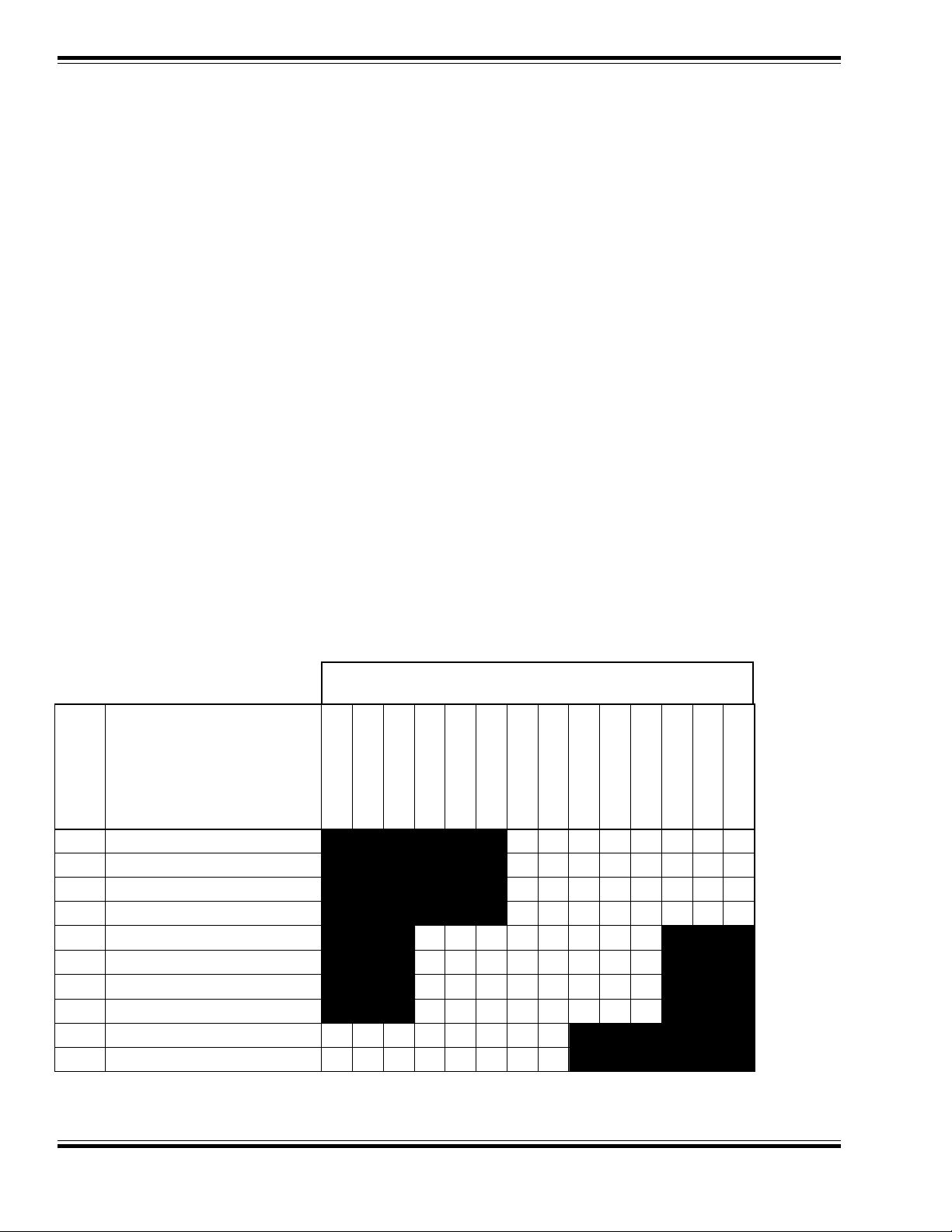
CVs 33-42 allow the user to customize which DSD outputs or sound effects are controlled by which
function keys . Each function input, FL through F8, is assigned a unique CV that allows the corresponding
function control to be redirected to up to eight different DSD function outputs or sound effects. This
allows a single function key to control more than one output if desired.
This feature is especially useful when the DSD is used with a controller that has less than eight function
keys as the user can select which DSD outputs and sounds are important and re-map them to the
available function keys. Some outputs or sounds can be sensibly tied to another output thus freeing up a
function. For example, the dynamo sound could be configured to turn on whenever the headlight or
backup light was on.
It is also possible to control a given output with more than one function k e y. In this case, the output will be
turned on when any of the corresponding function inputs are active. The output will turn off only when all
relevant inputs have also been turned off.
The FL function has two CVs - one for forward direction and one for reverse. Function outputs mapped to
these registers will be directional unless the same output is mapped to both CVs.
Note that all function inputs cannot be mapped to all outputs. The matrix below graphically indicates
which inputs can control which outputs:
DSD OUTPUT
CV
33
34
35
36
37
38
39
40
41
42
FUNCTION
INPUT
FL (Fwd)
FL (Rev)
Function 1
Function 2
Function 3
Function 4
Function 5
Function 6
Function 7
Function 8
Mute
d
d
d
d
d
d
d
d
d
d
Coupler
Dynamo
F5 Output
Hiss
Bell
Whistle
F1 Output
Backup Light
Headlight
Note: d = default setting.
24
Digital Sound Decoder Technical Reference
Page 25

Address Mode Direct Mode
CV 33
FL(f) OUTPUT
❐■
Register Mode Ops Mode Shor t Form
❐❐
Paged Mode Ops Mode Long Form
■■
LOCATION
Description
Maps the FL(fwd) function to any of eight DSD auxiliary function outputs as defined by a 1 in the
corresponding bit position:
bit 7 bit 0
DYNO F5 HISS BELL WHSTL F1 BL HL
Bit 0: HL, Head light output
0 = Output is unaffected by FL(fwd).
1 = Output is activated when FL(fwd) is on.
Bit 1: BL, Backup light output
0 = Output is unaffected by FL(fwd).
1 = Output is activated when FL(fwd) is on.
Bit 2: F1, Function 1 Output
0 = Output is unaffected by FL(fwd).
1 = Output is activated when FL(fwd) is on.
Bit 3: WHSTL, Whistle Sound Effect
0 = Sound is unaffected by FL(fwd).
1 = Sound is activated when FL(fwd) is on.
Bit 4: BELL, Bell Sound Effect
0 = Sound is unaffected by FL(fwd).
1 = Sound is activated when FL(fwd) is on.
Bit 5: HISS, Cylinder Blowdown/Hiss Sound Effect
0 = Sound is unaffected by FL(fwd).
1 = Sound is activated when FL(fwd) is on.
Bit 6: F5, Function 5 Output
0 = Output is unaffected by FL(fwd).
1 = Output is activated when FL(fwd) is on.
Bit 7: DYNO, Dynamo Sound Effect
0 = Sound is unaffected by FL(fwd).
1 = Sound is activated when FL(fwd) is on.
A value of 00, sets FL(fwd) to control HL output.
Default V alue:1
Related CVs: See also CVs 33-42.
Digital Sound Decoder Technical Reference
25
Page 26

❐■
CV 34
FL(r) OUTPUT
Address Mode Direct Mode
❐❐
Register Mode Ops Mode Short Form
■■
Paged Mode Ops Mode Long Form
LOCATION
Description
Maps the FL(rev) function to any of eight DSD auxiliary function outputs as defined by a 1 in the
corresponding bit position:
bit 7 bit 0
DYNO F5 HISS BELL WHSTL F1 BL HL
Bit 0: HL, Head light output
0 = Output is unaffected by FL(rev).
1 = Output is activated when FL(rev) is on.
Bit 1: BL, Backup light output
0 = Output is unaffected by FL(rev).
1 = Output is activated when FL(rev) is on.
Bit 2: F1, Function 1 Output
0 = Output is unaffected by FL(rev).
1 = Output is activated when FL(rev) is on.
Bit 3: WHSTL, Whistle Sound Effect
0 = Sound is unaffected by FL(rev).
1 = Sound is activated when FL(rev) is on.
Bit 4: BELL, Bell Sound Effect
0 = Sound is unaffected by FL(rev).
1 = Sound is activated when FL(rev) is on.
Bit 5: HISS, Cylinder Blowdown/Hiss Sound Effect
0 = Sound is unaffected by FL(rev).
1 = Sound is activated when FL(rev) is on.
Bit 6: F5, Function 5 Output
0 = Output is unaffected by FL(rev).
1 = Output is activated when FL(rev) is on.
Bit 7: DYNO, Dynamo Sound Effect
0 = Sound is unaffected by FL(rev).
1 = Sound is activated when FL(rev) is on.
A value of 00 sets FL(rev) to control BL output.
Default V alue:2
Related CVs: See also CVs 33-42.
26
Digital Sound Decoder Technical Reference
Page 27

❐■
CV 35
F1 OUTPUT
Address Mode Direct Mode
❐❐
Register Mode Ops Mode Shor t Form
■■
Paged Mode Ops Mode Long Form
LOCATION
Description
Maps the F1 function to any of eight DSD auxiliary function outputs as defined by a 1 in the
corresponding bit position:
bit 7 bit 0
DYNO F5 HISS BELL WHSTL F1 BL HL
Bit 0: HL, Head light output
0 = Output is unaffected by F1.
1 = Output is activated when F1 is on.
Bit 1: BL, Backup light output
0 = Output is unaffected by F1.
1 = Output is activated when F1 is on.
Bit 2: F1, Function 1 Output
0 = Output is unaffected by F1.
1 = Output is activated when F1 is on.
Bit 3: WHSTL, Whistle Sound Effect
0 = Sound is unaffected by F1.
1 = Sound is activated when F1 is on.
Bit 4: BELL, Bell Sound Effect
0 = Sound is unaffected by F1.
1 = Sound is activated when F1 is on.
Bit 5: HISS, Cylinder Blowdown/Hiss Sound Effect
0 = Sound is unaffected by F1.
1 = Sound is activated when F1 is on.
Bit 6: F5, Function 5 Output
0 = Output is unaffected by F1.
1 = Output is activated when F1 is on.
Bit 7: DYNO, Dynamo Sound Effect
0 = Sound is unaffected by F1.
1 = Sound is activated when F1 is on.
A value of 00 sets F1 to control F1 output.
Default V alue:4
Related CVs:
Digital Sound Decoder Technical Reference
See also CVs 33-42.
27
Page 28

❐■
CV 36
F2 OUTPUT
Address Mode Direct Mode
❐❐
Register Mode Ops Mode Short Form
■■
Paged Mode Ops Mode Long Form
LOCATION
Description
Maps the F2 function to any of eight DSD auxiliary function outputs as defined by a 1 in the
corresponding bit position:
bit 7 bit 0
DYNO F5 HISS BELL WHSTL F1 BL HL
Bit 0: HL, Head light output
0 = Output is unaffected by F2.
1 = Output is activated when F2 is on.
Bit 1: BL, Backup light output
0 = Output is unaffected by F2.
1 = Output is activated when F2 is on.
Bit 2: F1, Function 1 Output
0 = Output is unaffected by F2.
1 = Output is activated when F2 is on.
Bit 3: WHSTL, Whistle Sound Effect
0 = Sound is unaffected by F2.
1 = Sound is activated when F2 is on.
Bit 4: BELL, Bell Sound Effect
0 = Sound is unaffected by F2.
1 = Sound is activated when F2 is on.
Bit 5: HISS, Cylinder Blowdown/Hiss Sound Effect
0 = Sound is unaffected by F2.
1 = Sound is activated when F2 is on.
Bit 6: F5, Function 5 Output
0 = Output is unaffected by F2.
1 = Output is activated when F2 is on.
Bit 7: DYNO, Dynamo Sound Effect
0 = Sound is unaffected by F2.
1 = Sound is activated when F2 is on.
A value of 00 sets F2 to control the WHISTLE sound effect.
Default V alue:8
Related CVs: See also CVs 33-42.
28
Digital Sound Decoder Technical Reference
Page 29

Address Mode Direct Mode
CV 37
F3 OUTPUT
❐■
Register Mode Ops Mode Shor t Form
❐❐
Paged Mode Ops Mode Long Form
■■
LOCATION
Description
Maps the F3 function to any of eight DSD auxiliary function outputs as defined by a 1 in the
corresponding bit position:
bit 7 bit 0
CPLR DYNO F5 HISS BELL WHSTL
Bit 0: WHSTL, Whistle Sound Effect
0 = Sound is unaffected by F3.
1 = Sound is activated when F3 is on.
Bit 1: BELL, Bell Sound Effect
0 = Sound is unaffected by F3.
1 = Sound is activated when F3 is on.
Bit 2: HISS, Cylinder Blowdown/Hiss Sound Effect
0 = Sound is unaffected by F3.
1 = Sound is activated when F3 is on.
Bit 3: F5, Function 5 Output
0 = Output is unaffected by F3.
1 = Output is activated when F3 is on.
Bit 4: DYNO, Dynamo Sound Effect
0 = Sound is unaffected by F3.
1 = Sound is activated when F3 is on.
Bit 5: CPLR, Coupler Sound Effect
0 = Sound is unaffected by F3.
1 = Sound is activated when F3 is on.
Bit 6: Reserved
Bit 7: Reserved
A value of 00 sets F3 to control the BELL sound effect.
Default V alue:2
Related CVs: See also CVs 33-42.
Digital Sound Decoder Technical Reference
29
Page 30

Address Mode Direct Mode
CV 38
F4 OUTPUT
❐■
Register Mode Ops Mode Short Form
❐❐
Paged Mode Ops Mode Long Form
■■
LOCATION
Description
Maps the F4 function to any of eight DSD auxiliary function outputs as defined by a 1 in the
corresponding bit position:
bit 7 bit 0
CPLR DYNO F5 HISS BELL WHSTL
Bit 0: WHSTL, Whistle Sound Effect
0 = Sound is unaffected by F4.
1 = Sound is activated when F4 is on.
Bit 1: BELL, Bell Sound Effect
0 = Sound is unaffected by F4.
1 = Sound is activated when F4 is on.
Bit 2: HISS, Cylinder Blowdown/Hiss Sound Effect
0 = Sound is unaffected by F4.
1 = Sound is activated when F4 is on.
Bit 3: F5, Function 5 Output
0 = Output is unaffected by F4.
1 = Output is activated when F4 is on.
Bit 4: DYNO, Dynamo Sound Effect
0 = Sound is unaffected by F4.
1 = Sound is activated when F4 is on.
Bit 5: CPLR, Coupler Sound Effect
0 = Sound is unaffected by F4.
1 = Sound is activated when F4 is on.
Bit 6: Reserved
Bit 7: Reserved
A value of 00 sets F4 to control the HISS sound effect.
Default V alue:4
Related CVs: See also CVs 33-42.
30
Digital Sound Decoder Technical Reference
Page 31

Address Mode Direct Mode
CV 39
F5 OUTPUT
❐■
Register Mode Ops Mode Shor t Form
❐❐
Paged Mode Ops Mode Long Form
■■
LOCATION
Description
Maps the F5 function to any of eight DSD auxiliary function outputs as defined by a 1 in the
corresponding bit position:
bit 7 bit 0
CPLR DYNO F5 HISS BELL WHSTL
Bit 0: WHSTL, Whistle Sound Effect
0 = Sound is unaffected by F5.
1 = Sound is activated when F5 is on.
Bit 1: BELL, Bell Sound Effect
0 = Sound is unaffected by F5.
1 = Sound is activated when F5 is on.
Bit 2: HISS, Cylinder Blowdown/Hiss Sound Effect
0 = Sound is unaffected by F5.
1 = Sound is activated when F5 is on.
Bit 3: F5, Function 5 Output
0 = Output is unaffected by F5.
1 = Output is activated when F5 is on.
Bit 4: DYNO, Dynamo Sound Effect
0 = Sound is unaffected by F5.
1 = Sound is activated when F5 is on.
Bit 5: CPLR, Coupler Sound Effect
0 = Sound is unaffected by F5.
1 = Sound is activated when F5 is on.
Bit 6: Reserved
Bit 7: Reserved
A value of 00 sets F5 to control the F5 function output.
Default V alue:8
Related CVs: See also CVs 33-42.
Digital Sound Decoder Technical Reference
31
Page 32

Address Mode Direct Mode
CV 40
F6 OUTPUT
❐■
Register Mode Ops Mode Short Form
❐❐
Paged Mode Ops Mode Long Form
■■
LOCATION
Description
Maps the F6 function to any of eight DSD auxiliary function outputs as defined by a 1 in the
corresponding bit position:
bit 7 bit 0
CPLR DYNO F5 HISS BELL WHSTL
Bit 0: WHSTL, Whistle Sound Effect
0 = Sound is unaffected by F6.
1 = Sound is activated when F6 is on.
Bit 1: BELL, Bell Sound Effect
0 = Sound is unaffected by F6.
1 = Sound is activated when F6 is on.
Bit 2: HISS, Cylinder Blowdown/Hiss Sound Effect
0 = Sound is unaffected by F6.
1 = Sound is activated when F6 is on.
Bit 3: F5, Function 5 Output
0 = Output is unaffected by F6.
1 = Output is activated when F6 is on.
Bit 4: DYNO, Dynamo Sound Effect
0 = Sound is unaffected by F6.
1 = Sound is activated when F6 is on.
Bit 5: CPLR, Coupler Sound Effect
0 = Sound is unaffected by F6.
1 = Sound is activated when F6 is on.
Bit 6: Reserved
Bit 7: Reserved
A value of 00 sets F6 to control the DYNAMO sound effect.
Default V alue: 16 (0x10)
Related CVs: See also CVs 33-42.
32
Digital Sound Decoder Technical Reference
Page 33

❐■
CV 41
F7 OUTPUT
Address Mode Direct Mode
❐❐
Register Mode Ops Mode Shor t Form
■■
Paged Mode Ops Mode Long Form
LOCATION
Description
Maps the F7 function to any of eight DSD auxiliary function outputs as defined by a 1 in the
corresponding bit position:
bit 7 bit 0
MUTE CPLR DYNO F5
Bit 0: F5, Function 5 Output
0 = Output is unaffected by F7.
1 = Output is activated when F7 is on.
Bit 1: DYNO, Dynamo Sound Effect
0 = Sound is unaffected by F7.
1 = Sound is activated when F7 is on.
Bit 2: CPLR, Coupler Sound Effect
0 = Sound is unaffected by F7.
1 = Sound is activated when F7 is on.
Bit 3: Reserved
Bit 4: Reserved
Bit 5: Reserved
Bit 6: Reserved
Bit 7: MUTE, Audio Mute Function
0 = Sound is unaffected by F7.
1 = Sound is muted when F7 is on.
A value of 00 sets F7 to control the COUPLER sound effect.
Default V alue:4
Related CVs: See also CVs 33-42.
Digital Sound Decoder Technical Reference
33
Page 34

❐■
CV 42
F8 OUTPUT
Address Mode Direct Mode
❐❐
Register Mode Ops Mode Short Form
■■
Paged Mode Ops Mode Long Form
LOCATION
Description
Maps the F8 function to any of eight DSD auxiliary function outputs as defined by a 1 in the
corresponding bit position:
bit 7 bit 0
MUTE CPLR DYNO F5
Bit 0: F5, Function 5 Output
0 = Output is unaffected by F8.
1 = Output is activated when F8 is on.
Bit 1: DYNO, Dynamo Sound Effect
0 = Sound is unaffected by F8.
1 = Sound is activated when F8 is on.
Bit 2: CPLR, Coupler Sound Effect
0 = Sound is unaffected by F8.
1 = Sound is activated when F8 is on.
Bit 3: Reserved
Bit 4: Reserved
Bit 5: Reserved
Bit 6: Reserved
Bit 7: MUTE, Audio Mute Function
0 = Sound is unaffected by F8.
1 = Sound is muted when F8 is on.
A value of 00 sets F8 to control the MUTE function.
Default V alue: 128 (0x80)
Related CVs: See also CVs 33-42.
34
Digital Sound Decoder Technical Reference
Page 35

Address Mode Direct Mode
CV 49
HYPERLIGHT
❐■
Register Mode Ops Mode Shor t Form
❐❐
Paged Mode Ops Mode Long Form
■■
CONFIGURATION
Description
Used to reconfigure the F1 and F5 lighting outputs to one of four Hyperlight lighting effects:
bit 7 bit 0
F5.1 F5.0 F1.1 F1.0
Bits 1-0: F1.1:F1.0, Function 1 Output Configuration
00 = Standard On/Off output
01 = Mars Light Effect
10 = Firebox Flicker Effect
11 = Synchronized Firebox Flicker - Turns on and off with sound effect of
firebox door opening and closing.
Bits 2-3: F5.1:F5.0, Function 5 Output Configuration
00 = Standard On/Off output
01 = Mars Light Effect
10 = Firebox Flicker Effect
11 = Synchronized Firebox Flicker - Turns on and off with sound effect of
firebox door opening and closing.
Bit 4-7: Reserved
Note: the selected lighting effect will not turn on until the appropriate function key is on as well.
Default V alue: 0, F1 = On/Off Output, F5 = On/Off Output
Digital Sound Decoder Technical Reference
35
Page 36

❐■
CV 50
VOLUME CONTROL
Description
Contains a value between 0 and 15 (0x0F) to used to set the overall volume level of the DSD
sound effects:
bit 7 bit 0
Bits 0-3: D0-D3, V olume Control
Bit 4-7: Reserved
Setting this CV to 15 will provide maximum volume. A setting of 0 will mute all sound effects.
Address Mode Direct Mode
❐❐
Register Mode Ops Mode Short Form
■■
Paged Mode Ops Mode Long Form
D3 D2 D1 D0
Default V alue: 08 (0x08), 50% Volume
36
Digital Sound Decoder Technical Reference
Page 37

Address Mode Direct Mode
CV 51
B ACKGROUND
❐■
Register Mode Ops Mode Shor t Form
❐❐
Paged Mode Ops Mode Long Form
■■
SOUND
CONFIGURATION BYTE
Description
This CV is used to selectively enable the DSD’s various background sound effects:
bit 7 bit 0
AUTO ABD POP PGG FRED BLWR APUMP RTC
Bit 0: RTC, Real Time Clock Mode
0 = Background sound effects are spaced at scale time inter vals ranging
typically between 2-20 minutes.
1 = Background sound effects are spaced at real time inter vals ranging
typically between 20 minutes to several hours
.
Bit 1: APUMP, Airpump Sound Enable
0 = Airpump sound effect is turned off.
1 = Airpump sound effect is turned on.
Bit 2: BLWR, Blower Sound Enable
0 = Blower sound effect is disabled.
1 = Blower sound effect is enabled.
Note: Blower sound is always on. This bit enables the effect of increasing blower draft while the engine is idle.
Bit 3: FRED, Fireman Fred Sound Enable
0 = Fireman Fred sound effect is disabled.
1 = Fireman Fred sound effect is enabled.
Bit 4: PGG, Pneumatic Grease Gun Sound Enable
0 = Grease Gun sound effect is disabled.
1 = Grease Gun sound effect is enabled.
Bit 5: POP, Boiler Pop Valve Blowoff Sound Enable
0 = Pop Valve sound effect is disabled.
1 = Pop Valve sound effect is enabled.
Bit 6: ABD, Automatic Cylinder Blow Down Enable
0 = Blow down effect is activated by function key.
1 = Blow down effect is activated by engine stops.
Bit 7: BGND, Background sound effect global enable
0 = All background sound effects are disabled.
1 = All selected background sound effects are enabled.
Default V alue: 190 (0xBE), All sound effects are enabled. Auto-Blowdown is disabled.
Digital Sound Decoder Technical Reference
37
Page 38

❐■
CV 52
FOREGROUND
Address Mode Direct Mode
❐❐
Register Mode Ops Mode Short Form
■■
Paged Mode Ops Mode Long Form
SOUND
CONFIGURATION BYTE
Description
This CV is used to configure the DSD’s foreground sound effects:
bit 7 bit 0
RNG3 RNG2 RNG1 RNG0 APS CAM DDE AECS
Bit 0: AECS, Articulated Exhaust Cadence Select
0 = Exhaust Timing emulates 2 cylinder locos and shays.
1 = Exhaust Timing emulates articulated locos.
Bit 1: DDE, Dynamic Digital Exhaust Enable
0 = DDE sound processor is disabled.
1 = DDE sound processor is enabled.
Bit 2: CAM Enable
0 = Exhaust Chuff is synchronized to throttle.
1 = Exhaust Chuff is synchronized with cam.
Bit 3: APS, Dual Airpump Select
0 = Single Airpump sound effect.
1 = Dual Airpump sound effect.
Note: CV 51, Bit 1 must be set for this sound to be heard.
Bit 4-7: RNG3:RNG1, Bell Ring Rate
Controls the ringing rate of the bell sound.
0000 = Fastest Ring Rate
1111 = Slowest Ring Rate
Default V alue: 70 (0x46), Auto-Exhaust Cadence = 2 Cylinder Loco
Dynamic Digital Exhaust Enabled
Single Airpump
Exhaust Cam Enabled
Bell Ring Rate = 100 (mid speed).
Related CVs: See also Auto Exhaust Sync Rate (CV 54).
38
Digital Sound Decoder Technical Reference
Page 39

❐■
CV 53
SOUND
Address Mode Direct Mode
❐❐
Register Mode Ops Mode Shor t Form
■■
Paged Mode Ops Mode Long Form
CONFIGURATION
BYTE #3
Description
This CV controls the power-up state of the sound effects:
bit 7 bit 0
QUIET
Bit 0: QUIET
0 = Sound turns on a few seconds after power is turned on.
1 = Sound turns on only when the DSD receives a packet with
a matching address.
Bits 1-7: Reserved
The Quiet bit is used for "noise control' when many DSD equipped engines are on a la y out. When
set to 1, locomotives not in use will remain quiet until they are called into service.
Default V alue:0
Digital Sound Decoder Technical Reference
39
Page 40

Address Mode Direct Mode
CV 54
AUTO EXHAUST
❐■
Register Mode Ops Mode Short Form
❐❐
Paged Mode Ops Mode Long Form
■■
SYNC RATE
Description
This CV contains a value n between 0 and 255 that specifies the chuff synchronization rate as a
proportion of the throttle for Auto-Exhaust operation.
bit 7 bit 0
CAM AE6 AE5 AE4 AE3 AE2 AE1 AE0
Bits 0-7: AE7:AE0, Auto Exhaust/Cutoff Control Rate
For Auto-Exhaust synchronization, the chuff rate will be generated in proportion the throttle setting. To select Auto-Exhaust mode, the CV is loaded with any value between 0 and 255 (0xFF).
Higher values will yield higher chuff rates for a given throttle setting. A value of 0 will disable the
exhaust sound.
The correct synchronization rate may be computed as:
CV Value = 115.9 X ———
Where SPD is the locomotive’s speed in scale miles-per-hour at maximum throttle and DIA is the
locomotive’s driver wheel diameter in scale inches. For geared engines , the CV value should also
be multiplied by the locomotive's gear ratio.
When using cam synchronization, this CV will control the exhaust cutoff rate. To get optimal
performance over the entire throttle range, the CV value should be calculated using the formula
above.
SPD
DIA
Default V alue: 94 (0x5E)
Related CVs: See also Foreground Sound Configuration.
40
Digital Sound Decoder Technical Reference
Page 41

❐■
CV 55
EXHAUST TONE
Address Mode Direct Mode
❐❐
Register Mode Ops Mode Shor t Form
■■
Paged Mode Ops Mode Long Form
CONTROL
Description
This CV contains a value between 0 and 63 that sets tone of the exhaust chuff:
bit 7 bit 0
TONE5 TONE4 TONE3 TONE2 T ONE1 TONE0
Bits 0-5: TONE5:TONE0, Exhaust Tone Control
Bits 6-7: Reserved
This CV controls the over all tone of the e xhaust chuff . Higher values increase the high-frequency
component of the sound.
Default V alue:08
Digital Sound Decoder Technical Reference
41
Page 42

❐■
CV 56
EXHA UST V OLUME
Address Mode Direct Mode
❐❐
Register Mode Ops Mode Short Form
■■
Paged Mode Ops Mode Long Form
CONTROL
Description
This CV contains a value between 0 and 255 that controls the exhaust chuff volume:
bit 7 bit 0
VOL7 VOL6 VOL5 VOL4 VOL3 VOL2 VOL1 VOL0
Bits 0-7: VOL7:VOL0, Exhaust Volume Control
This CV controls the overall volume of the exhaust chuff when the Dynamic Digital Exhaust
processor is disabled. Higher values will increase the volume level. When the DDE processor is
on, this CV will have no effect.
Default V alue: 255 (0x255)
See Also: Foreground Sound Configuration
42
Digital Sound Decoder Technical Reference
Page 43

Address Mode Direct Mode
CV 66
FORWARD TRIM
❐■
Register Mode Ops Mode Shor t Form
❐❐
Paged Mode Ops Mode Long Form
■■
Description
Contains a value, n, between 0 and 255 that specifies a scaling factor interpreted as
N/128 by which the forward drive voltage is multiplied.
bit 7 bit 0
D7 D6 D5 D4 D3 D2 D1 D0
D0-D7: Forward Trim Scalar
The forward trim scalar allows the decoder’s overall throttle response in the forward direction to
be adjusted up or down for the purpose of matching one locomotive’s speed cur ve to another.
See graph below.
A trim value of 128 (0x80) yields a scaling factor of 1.0 which will ha v e no net eff ect on the speed
response.
Trim values between 129 and 255 (0x81-0xFF) ha ve the eff ect of increasing the motor v oltage b y
a factor ranging between 1.01 to 1.99.
Trim values between 1 and 127 (0x01-0x7F) will decrease the motor v oltage b y a f actor betw een
0.008 and 0.99.
A trim value of 0 disables the trim scalar
computation.
100%
CV66 = 255
CV66 = 128
This CV is used only when speed tables are
enabled (CV 29, Bit 4 = 1). Otherwise, this
75%
CV will have no effect.
50%
25%
CV66 = 64
Default V alue: 128 (0x80)
Related CVs: See also Reverse Trim, CV 29.
Digital Sound Decoder Technical Reference
0%
0 14 28
43
Page 44

Address Mode Direct Mode
CV 67-94
LOADABLE SPEED
❐■
Register Mode Ops Mode Short Form
❐❐
Paged Mode Ops Mode Long Form
■■
TABLE
Description
The loadable speed table is made up of 28 CVs . Each CV contains a value , n, between 0 and 255
that specifies the percentage of the maximum throttle voltage interpreted as n/255 that is to be
applied to the motor when the speed step in use corresponds to that CV.
bit 7 bit 0
D7 D6 D5 D4 D3 D2 D1 D0
D0-D7: Speed Table Data
The loadable speed table ma y be used in the 14, 28 and 128 speed step modes . When 14 speed
step mode is in effect, the DSD will use a curve defined by e v ery other speed table v alue starting
with speed step 1.
When 28 step mode is enabled, the DSD will simply use one table value for each speed step.
When 128 step mode is enabled, the DSD will interpolate 4-5 points between each speed table
entry to build a 128 point curve.
Note that the DSD will not use the loadable speed table until bit 5 in
to 1.
Default values: The default values provide a linear (straight line) response. Individual CVs are
loaded as follows:
CV 67 (Speed Step 1): 0 (0x00)
CV 68 (Speed Step 2): 9 (0x09)
CV 69 (Speed Step 3): 18 (0x12)
CV 70 (Speed Step 4): 28 (0x1C)
CV 71 (Speed Step 5): 37 (0x25)
CV 72 (Speed Step 6): 47 (0x2F)
CV 73 (Speed Step 7): 56 (0x38)
CV 74 (Speed Step 8): 66 (0x42)
CV 75 (Speed Step 9): 75 (0x4B)
CV 76 (Speed Step 10): 85 (0x55)
CV 77 (Speed Step 11): 94 (0x5E)
CV 78 (Speed Step 12): 103 (0x67)
CV 79 (Speed Step 13): 113 (0x71)
CV 80 (Speed Step 14): 122 (0x7A)
both
CV 25 and CV 29 are set
44
Digital Sound Decoder Technical Reference
Page 45

CV 81 (Speed Step 15): 132 (0x84)
CV 82 (Speed Step 16): 141 (0x8D)
CV 83 (Speed Step 17): 151 (0x97)
Address Mode Direct Mode
Register Mode Ops Mode Shor t Form
Paged Mode Ops Mode Long Form
CV 84 (Speed Step 18): 160 (0xA0)
CV 85 (Speed Step 19): 170 (0xAA)
CV 86 (Speed Step 20): 179 (0xB3)
CV 87 (Speed Step 21): 188 (0xBC)
CV 88 (Speed Step 22): 198 (0xC6)
CV 89 (Speed Step 23): 207 (0xCF)
CV 90 (Speed Step 24): 217 (0xD9)
CV 91 (Speed Step 25): 226 (0xE2)
CV 92 (Speed Step 26): 236 (0xEC)
CV 93 (Speed Step 27): 245 (0xF5)
CV 94 (Speed Step 28): 255 (0xFF)
Related CVs: See also CV 29, Speed Table Select Register.
Digital Sound Decoder Technical Reference
45
Page 46

❐■
CV 95
REVERSE TRIM
Description
Contains a value, n, between 0 and 255 that specifies a scaling factor interpreted as
N/128 by which the reverse dr ive voltage is multiplied.
bit 7 bit 0
D7 D6 D5 D4 D3 D2 D1 D0
D0-D7: Reverse Trim Scalar
The reverse trim scalar allows the decoder’s overall throttle response in the reverse direction to
be adjusted up or down for the purpose of matching one locomotive’s speed curve to another.
A trim value of 128 (0x80) yields a scaling factor of 1.0 which will ha v e no net eff ect on the speed
response.
Address Mode Direct Mode
❐❐
Register Mode Ops Mode Short Form
■■
Paged Mode Ops Mode Long Form
Trim values between 129 and 255 (0x81-0xFF) ha ve the eff ect of increasing the motor v oltage b y
a factor ranging between 1.01 to 1.99.
Trim values between 1 and 127 (0x01-0x7F) will decrease the motor voltage by a factor between
0.008 and 0.99.
A trim value of 0 disables the trim scalar computation.
This CV is used only when speed tables are enabled (CV 29, Bit 4 = 1). Otherwise, this CV will
have no effect.
Default V alue: 128 (0x80)
Related CVs: See also Forward Trim, CV 29.
46
Digital Sound Decoder Technical Reference
Page 47

❐■
CV 105
USER IDENTIFIER #1
Description
Provides storage for user supplied data such as purchase date, serial numbers, spouse’s birthday, etc. This CV otherwise has no effect on the DSD operation.
bit 7 bit 0
D7 D6 D5 D4 D3 D2 D1 D0
D0-D7: User Identifier data
This CV may be programmed with any value between 0 and 255 (0x00-0xFF).
Address Mode Direct Mode
❐❐
Register Mode Ops Mode Shor t Form
■■
Paged Mode Ops Mode Long Form
Default V alue:0
Related CVs: See also User Identifier #2.
Digital Sound Decoder Technical Reference
47
Page 48

Address Mode Direct Mode
CV 106
USER IDENTIFIER #2
Description
Provides storage for user supplied data such as purchase date, serial numbers, spouse’s bir th-
day, etc. This CV otherwise has no effect on the DSD operation.
bit 7 bit 0
D7 D6 D5 D4 D3 D2 D1 D0
D0-D7: User Identifier data
This CV may be programmed with any value between 0 and 255 (0x00-0xFF).
❐■
Register Mode Ops Mode Short Form
❐❐
Paged Mode Ops Mode Long Form
■■
Default V alue:0
Related CVs: See also User Identifier #1.
48
Digital Sound Decoder Technical Reference
Page 49
©1998 Throttle Up! Corp.
DCC
gy
All Rights Reserved.
Revison B
COMP A TIBLE WITH
THE NMRA DCC STANDARDS
AND RECOMMENDED
PRACTICES
TM
New Dimensions in Digital Sound Technolo
210 Rock Point Drive Durango, CO 81301
(970) 259-0690 Fax: (970) 259-0691 Email: Sales@soundtraxx.com
 Loading...