

Page 1
CV 33-42CV 33-42
CV 33-42
CV 33-42CV 33-42
Address Mode Direct Mode
Register Mode Ops Mode Short Form
FUNCTION OUTPUTFUNCTION OUTPUT
FUNCTION OUTPUT
FUNCTION OUTPUTFUNCTION OUTPUT
MAPMAP
MAP
MAPMAP
Paged Mode Ops Mode Long Form
General Discussion
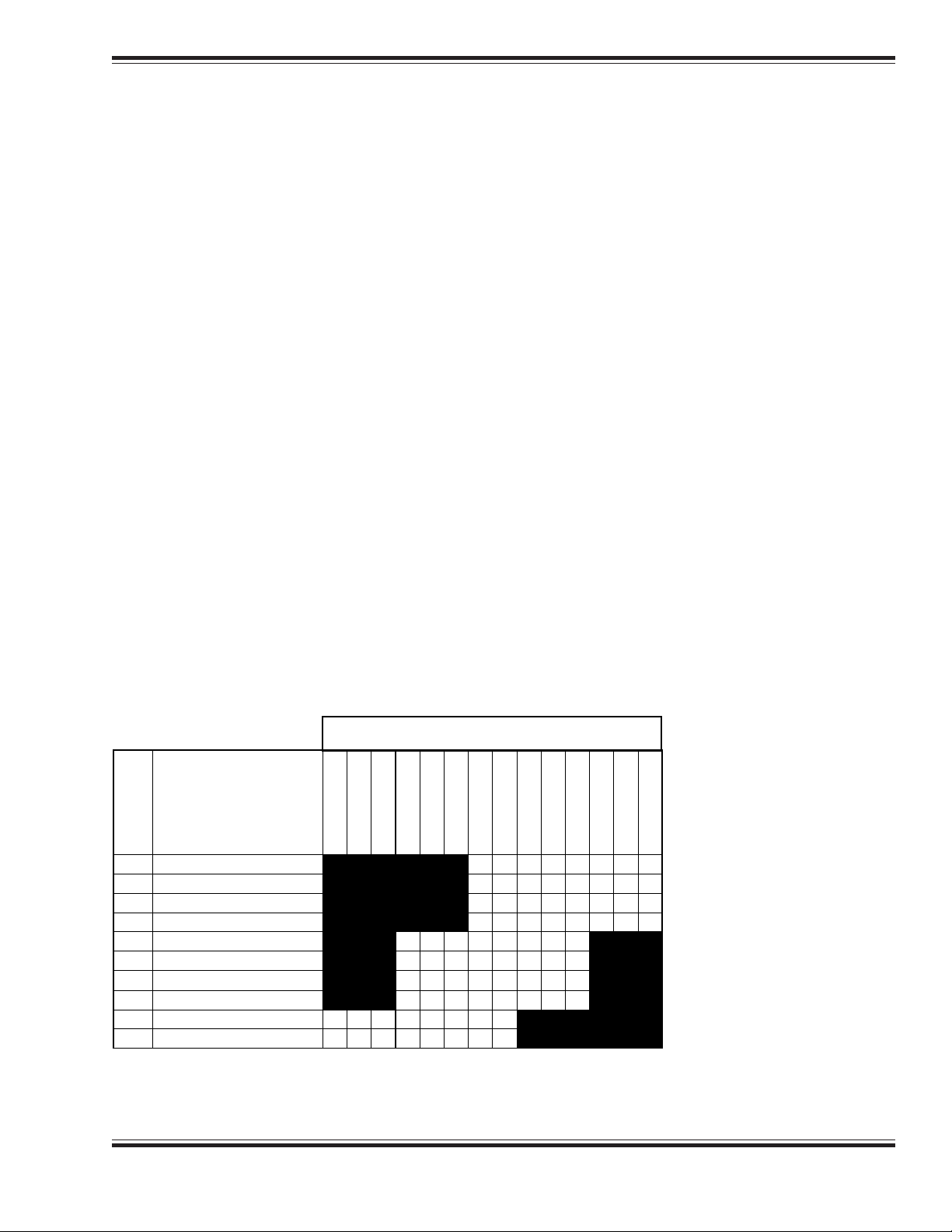
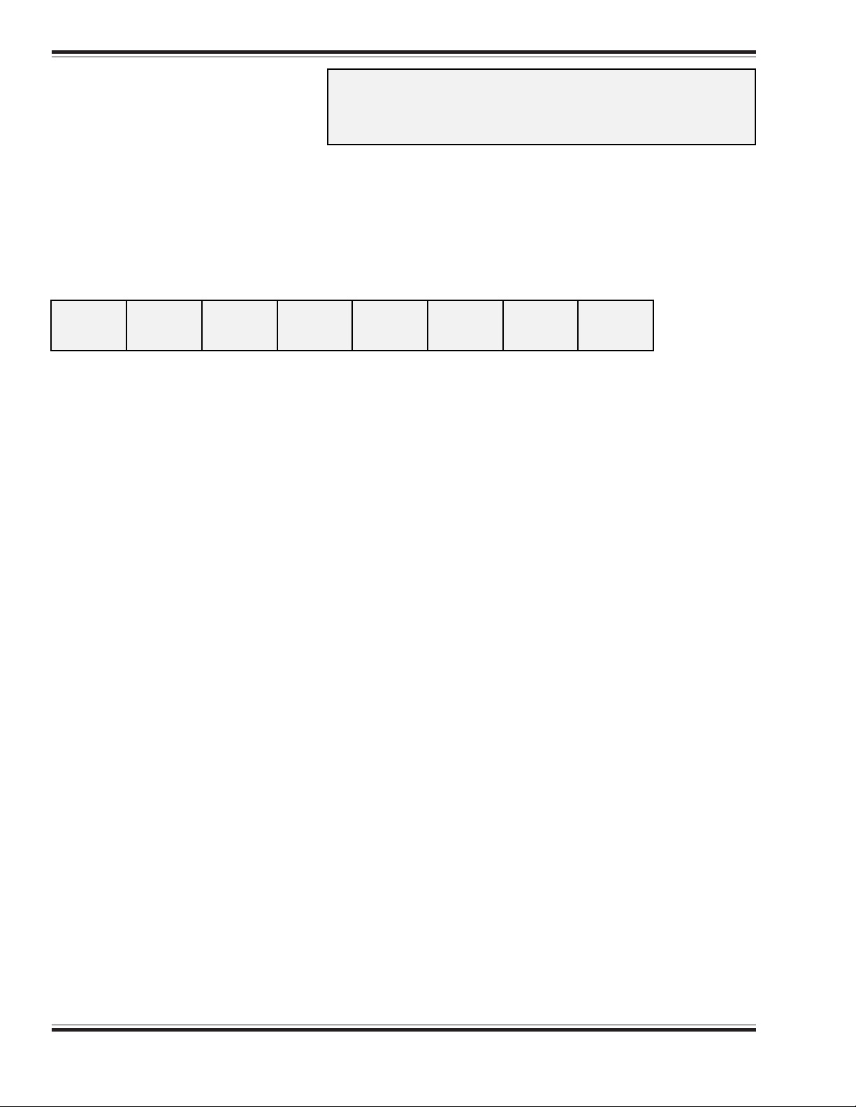
CVs 33-42 allow the user to customize which DSD outputs or sound effects are controlled by
which function keys. Each function input, F0 thru F8, is assigned a unique CV that allows the
corresponding function control to be redirected to up to eight different DSD Function outputs or
sound effects. This allows a single function key to control more than one output if desired.
This feature is especially useful when the DSD is used with a controller that has less than eight
function keys as the user can select which DSD outputs and sounds are important and remap
them to the available function keys. Some outputs or sounds can be sensibly tied to another
output thus freeing up a function. For example, the F5 and F6 lighting outputs could be configured to turn on whenever the headlight or backup light was on.
It is also possible to control a given output with more than one function key. In this case, the
output will be turned on when any of the corresponding function inputs are active. The output
will turn off only when all relevant inputs have also been turned off.
You will have to re-assign function mapping values to gain access to the manual engine notching controls, RPM+ and RPM-. This may mean giving up the use of an existing function and/or
doubling up on function outputs assigned to a function key.
Note that all function inputs cannot be mapped to all outputs. The matrix below graphically
indicates which inputs can control which outputs:
DIESEL DSD OUTPUT
CV
FUNCTION
INPUT
33
FL (Fwd) Function
34
FL (Rev)Function
35
Function 1
36
Function 2
37
Function 3
38
Function 4
39
Function 5
40
Function 6
41
Function 7
42
Function 8
*
*
Mute
Dimmer
Dynamic Brakes
Coupler
F6 Out
F5 Out
RPMs -
RPMs +
Horn
Bell
Reverse Light
d
d
d
d
d
d
d
d
d
d
Forward Light
Note: * = function output undefined
d = default setting.
Diesel Digital Sound Decoder Technical Reference
11
1
11
Page 2
CV 33CV 33
CV 33
CV 33CV 33
FL(f) OUTPUTFL(f) OUTPUT
FL(f) OUTPUT
FL(f) OUTPUTFL(f) OUTPUT
Address Mode Direct Mode
❐■
Register Mode Ops Mode Short Form
❐❐
Paged Mode Ops Mode Long Form
■■
LOCALOCA
LOCA
LOCALOCA
DescriptionDescription
Description
DescriptionDescription
TIONTION
TION
TIONTION
Maps the FL(fwd) function to any of eight DSD auxiliary function outputs as defined by a 1 in the
corresponding bit position:
bit 7 bit 0
F6 F6
F6
F6 F6
F5 F5
F5
F5 F5
Bit 0:Bit 0:
Bit 0: HL, Head light output
Bit 0:Bit 0:
Bit 1:Bit 1:
Bit 1: BL, Backup light output
Bit 1:Bit 1:
Bit 2:Bit 2:
Bit 2: BELL, Bell Sound Effect
Bit 2:Bit 2:
RPMs - RPMs -
RPMs -
RPMs - RPMs -
0 = Output is unaffected by FL(fwd).
1 = Output is activated when FL(fwd) is on.
0 = Output is unaffected by FL(fwd).
1 = Output is activated when FL(fwd) is on.
0 = Sound is unaffected by FL(fwd).
1 = Sound is activated when FL(fwd) is on.
RPMs + RPMs +
RPMs +
RPMs + RPMs +
HORN HORN
HORN
HORN HORN
BELL BELL
BELL
BELL BELL
BL BL
BL
BL BL
HL HL
HL
HL HL
Default Default
Default
Default Default
Bit 3:Bit 3:
Bit 3: HORN, Horn Sound Effect
Bit 3:Bit 3:
0 = Sound is unaffected by FL(fwd).
1 = Sound is activated when FL(fwd) is on.
Bit 4:Bit 4:
Bit 4: RPM +, Engine Exhaust Sound RPM Increase
Bit 4:Bit 4:
0 = Sound is unaffected by FL(fwd).
1 = RPMs are advanced one notch when FL(fwd) is on.
Bit 5:Bit 5:
Bit 5: RPM -, Engine Exhaust Sound RPM Decrease
Bit 5:Bit 5:
0 = Sound is unaffected by FL(fwd).
1 = RPMs are reduced one notch when FL(fwd) is on.
Bit 6:Bit 6:
Bit 6: F5, Function 5 Output
Bit 6:Bit 6:
0 = Output is unaffected by FL(fwd).
1 = Output is activated when FL(fwd) is on.
Bit 7:Bit 7:
Bit 7: F6, Function 6 Output
Bit 7:Bit 7:
0 = Output is unaffected by FL(fwd).
1 = Output is activated when FL(fwd) is on.
A value of 00, sets FL(fwd) to control HL output.
VV
aluealue
V
alue:01
VV
aluealue
Related CVsRelated CVs
Related CVs: See also CVs 33-42.
Related CVsRelated CVs
22
2
22
Diesel Digital Sound Decoder Technical Reference
Page 3
CV 34CV 34
CV 34
CV 34CV 34
FL(r) OUTPUTFL(r) OUTPUT
FL(r) OUTPUT
FL(r) OUTPUTFL(r) OUTPUT
Address Mode Direct Mode
❐■
Register Mode Ops Mode Short Form
❐❐
Paged Mode Ops Mode Long Form
■■
LOCALOCA
LOCA
LOCALOCA
DescriptionDescription
Description
DescriptionDescription
TIONTION
TION
TIONTION
Maps the FL(rev) function to any of eight DSD auxiliary function outputs as defined by a 1 in the
corresponding bit position:
bit 7 bit 0
F6 F6
F6
F6 F6
F5 RPMs - F5 RPMs -
F5 RPMs -
F5 RPMs - F5 RPMs -
Bit 0:Bit 0:
Bit 0: HL, Head light output
Bit 0:Bit 0:
0 = Output is unaffected by FL(rev).
1 = Output is activated when FL(rev) is on.
Bit 1:Bit 1:
Bit 1: BL, Backup light output
Bit 1:Bit 1:
0 = Output is unaffected by FL(rev).
1 = Output is activated when FL(rev) is on.
Bit 2:Bit 2:
Bit 2: BELL, Bell Sound Effect
Bit 2:Bit 2:
0 = Sound is unaffected by FL(rev).
1 = Sound is activated when FL(rev) is on.
RPMs + RPMs +
RPMs +
RPMs + RPMs +
HORN HORN
HORN
HORN HORN
BELL BELL
BELL
BELL BELL
BL BL
BL
BL BL
HLHL
HL
HLHL
Bit 3:Bit 3:
Bit 3: HORN, Horn Sound Effect
Bit 3:Bit 3:
0 = Sound is unaffected by FL(rev).
1 = Sound is activated when FL(rev) is on.
Bit 4:Bit 4:
Bit 4: RPMs +, Engine Exhaust Sound RPM Increase
Bit 4:Bit 4:
0 = Sound is unaffected by FL(rev).
1 = RPMs are advanced one notch by FL(rev).
Bit 5:Bit 5:
Bit 5: RPMs -, Engine Exhaust Sound RPM Decrease
Bit 5:Bit 5:
0 = Sound is unaffected by FL(rev).
1 = RPMs are reduced one notch by FL(rev).
Bit 6:Bit 6:
Bit 6: F5, Function 5 Output
Bit 6:Bit 6:
0 = Output is unaffected by FL(rev).
1 = Output is activated when FL(rev) is on.
Bit 7:Bit 7:
Bit 7: F6, Function 6 Output
Bit 7:Bit 7:
0 = Output is unaffected by FL(rev).
1 = Output is activated when FL(rev) is on.
A value of 00 sets FL(rev) to control BL output.
Default Default
Default
Default Default
VV
aluealue
V
alue:02
VV
aluealue
Related CVsRelated CVs
Related CVs: See also CVs 33-42.
Related CVsRelated CVs
Diesel Digital Sound Decoder Technical Reference
33
3
33
Page 4
CV 35CV 35
CV 35
CV 35CV 35
F1 OUTPUTF1 OUTPUT
F1 OUTPUT
F1 OUTPUTF1 OUTPUT
❐■
Address Mode Direct Mode
❐❐
Register Mode Ops Mode Short Form
■■
Paged Mode Ops Mode Long Form
LOCALOCA
LOCA
LOCALOCA
DescriptionDescription
Description
DescriptionDescription
TIONTION
TION
TIONTION
Maps the F1 function to any of eight DSD auxiliary function outputs as defined by a 1 in the
corresponding bit position:
bit 7 bit 0
F6 F6
F6
F6 F6
F5 F5
F5
F5 F5
Bit 0:Bit 0:
Bit 0: HL, Head light output
Bit 0:Bit 0:
Bit 1:Bit 1:
Bit 1: BL, Backup light output
Bit 1:Bit 1:
Bit 2:Bit 2:
Bit 2: BELL, Bell Sound Effect
Bit 2:Bit 2:
RPMs - RPMs -
RPMs -
RPMs - RPMs -
0 = Output is unaffected by F1.
1 = Output is activated when F1 is on.
0 = Output is unaffected by F1.
1 = Output is activated when F1 is on.
0 = Sound is unaffected by F1.
1 = Sound is activated when F1 is on.
RPMs + RPMs +
RPMs +
RPMs + RPMs +
HORN HORN
HORN
HORN HORN
BELL BELL
BELL
BELL BELL
BL BL
BL
BL BL
HLHL
HL
HLHL
Bit 3:Bit 3:
Bit 3: HORN, Horn Sound Effect
Bit 3:Bit 3:
0 = Sound is unaffected by F1.
1 = Sound is activated when F1 is on.
Bit 4:Bit 4:
Bit 4: RPMs +, Engine Exhaust Sound RPM Increase
Bit 4:Bit 4:
0 = Sound is unaffected by F1.
1 = RPMs are advanced one notch when F1 is on.
Bit 5:Bit 5:
Bit 5: RPMs -, Engine Exhaust Sound RPM Decrease
Bit 5:Bit 5:
0 = Sound is unaffected by F1.
1 = RPMs are reduced one notch when F1 is on.
Bit 6:Bit 6:
Bit 6: F5, Function 5 Output
Bit 6:Bit 6:
0 = Output is unaffected by F1.
1 = Output is activated when F1 is on.
Bit 7:Bit 7:
Bit 7: F6, Function 6 Output
Bit 7:Bit 7:
0 = Output is unaffected by F1.
1 = Output is activated when F1 is on.
A value of 00 sets F1 to control the Bell sound effect.
Default Default
Default
Default Default
VV
aluealue
V
alue:04
VV
aluealue
Related CVsRelated CVs
Related CVs: See also CVs 33-42.
Related CVsRelated CVs
44
4
44
Diesel Digital Sound Decoder Technical Reference
Page 5

CV 36CV 36
CV 36
CV 36CV 36
F2 OUTPUTF2 OUTPUT
F2 OUTPUT
F2 OUTPUTF2 OUTPUT
Address Mode Direct Mode
❐■
Register Mode Ops Mode Short Form
❐❐
Paged Mode Ops Mode Long Form
■■
LOCALOCA
LOCA
LOCALOCA
DescriptionDescription
Description
DescriptionDescription
TIONTION
TION
TIONTION
Maps the F2 function to any of eight DSD auxiliary function outputs as defined by a 1 in the
corresponding bit position:
bit 7 bit 0
F6 F6
F6
F6 F6
F5 RPMs - F5 RPMs -
F5 RPMs -
F5 RPMs - F5 RPMs -
Bit 0:Bit 0:
Bit 0: HL, Head light output
Bit 0:Bit 0:
0 = Output is unaffected by F2.
1 = Output is activated when F2 is on.
Bit 1:Bit 1:
Bit 1: BL, Backup light output
Bit 1:Bit 1:
0 = Output is unaffected by F2.
1 = Output is activated when F2 is on.
Bit 2:Bit 2:
Bit 2: BELL, Bell Sound Effect
Bit 2:Bit 2:
0 = Sound is unaffected by F2.
1 = Sound is activated when F2 is on.
RPMs + RPMs +
RPMs +
RPMs + RPMs +
HORN HORN
HORN
HORN HORN
BELL BELL
BELL
BELL BELL
BL BL
BL
BL BL
HLHL
HL
HLHL
Bit 3:Bit 3:
Bit 3: WHSTL, Whistle Sound Effect
Bit 3:Bit 3:
0 = Sound is unaffected by F2.
1 = Sound is activated when F2 is on.
Bit 4:Bit 4:
Bit 4: RPMs +, Engine Exhaust Sound RPM Increase
Bit 4:Bit 4:
0 = Sound is unaffected by F2.
1 = RPMs are advanced one notch when F2 is on.
Bit 5:Bit 5:
Bit 5: RPMs -, Engine Exhaust Sound RPM Decrease
Bit 5:Bit 5:
0 = Sound is unaffected by F2.
1 = RPMs are reduced one notch when F2 is on.
Bit 6:Bit 6:
Bit 6: F5, Function 5 Output
Bit 6:Bit 6:
0 = Output is unaffected by F2.
1 = Output is activated when F2 is on.
Bit 7:Bit 7:
Bit 7: F6, Function 6 Output
Bit 7:Bit 7:
0 = Output is unaffected by F2.
1 = Output is activated when F2 is on.
A value of 00 sets F2 to control the HORN sound effect.
Default Default
Default
Default Default
VV
aluealue
V
alue:08
VV
aluealue
Related CVsRelated CVs
Related CVs: See also CVs 33-42.
Related CVsRelated CVs
Diesel Digital Sound Decoder Technical Reference
55
5
55
Page 6
CV 37CV 37
CV 37
CV 37CV 37
F3 OUTPUTF3 OUTPUT
F3 OUTPUT
F3 OUTPUTF3 OUTPUT
❐■
Address Mode Direct Mode
❐❐
Register Mode Ops Mode Short Form
■■
Paged Mode Ops Mode Long Form
LOCALOCA
LOCA
LOCALOCA
DescriptionDescription
Description
DescriptionDescription
TIONTION
TION
TIONTION
Maps the F3 function to any of eight DSD auxiliary function outputs as defined by a 1 in the
corresponding bit position:
bit 7 bit 0
DIM D DIM D
DIM D
DIM D DIM D
YN BRKYN BRK
YN BRK
YN BRKYN BRK
Bit 0:Bit 0:
Bit 0: HORN,Horn Sound Effect
Bit 0:Bit 0:
Bit 1:Bit 1:
Bit 1: RPMs +, Engine Exhaust Sound RPM Increase
Bit 1:Bit 1:
Bit 2:Bit 2:
Bit 2: RPMs -, Engine Exhaust Sound RPM Decrease
Bit 2:Bit 2:
CPLR CPLR
CPLR
CPLR CPLR
0 = Sound is unaffected by F3.
1 = Sound is activated when F3 is on.
0 = Sound is unaffected by F3.
1 = RPMs are advanced one notch when F3 is on.
0 = Sound is unaffected by F3.
1 = RPMs are reduced one notch when F3 is on.
F6 F6
F6
F6 F6
F5 F5
F5
F5 F5
RPMs - RPMs -
RPMs -
RPMs - RPMs -
RPMs + HORN RPMs + HORN
RPMs + HORN
RPMs + HORN RPMs + HORN
Bit 3:Bit 3:
Bit 3: F5, Function 5 Output
Bit 3:Bit 3:
0 = Output is unaffected by F3.
1 = Output is activated when F3 is on.
Bit 4:Bit 4:
Bit 4: F6, Function 6 Output
Bit 4:Bit 4:
0 = Output is unaffected by F3.
1 = Output is activated when F3 is on.
Bit 5:Bit 5:
Bit 5: CPLR, Coupler Sound Effect
Bit 5:Bit 5:
0 = Sound is unaffected by F3.
1 = Sound is activated when F3 is on.
Bit 6:Bit 6:
Bit 6: DYN BRK, Dynamic Brake Sound Effect
Bit 6:Bit 6:
0 = Sound is unaffected by F3.
1 = Sound is activated when F3 is on.
Bit 7:Bit 7:
Bit 7: DIM, Headlight Dimmer Function
Bit 7:Bit 7:
0 = Lighting outputs are unaffected by F3.
1 = Lighting outputs setup as "Dimmable Headlights" are dimmed when F3 is on.
A value of 00 sets F3 to control the COUPLER sound effect.
Default Default
Default
Default Default
VV
aluealue
V
alue: 32 (0X20)
VV
aluealue
Related CVsRelated CVs
Related CVs: See also CVs 33-42.
Related CVsRelated CVs
66
6
66
Diesel Digital Sound Decoder Technical Reference
Page 7

CV 38CV 38
CV 38
CV 38CV 38
F4 OUTPUTF4 OUTPUT
F4 OUTPUT
F4 OUTPUTF4 OUTPUT
Address Mode Direct Mode
❐■
Register Mode Ops Mode Short Form
❐❐
Paged Mode Ops Mode Long Form
■■
LOCALOCA
LOCA
LOCALOCA
DescriptionDescription
Description
DescriptionDescription
TIONTION
TION
TIONTION
Maps the F4 function to any of eight DSD auxiliary function outputs as defined by a 1 in the
corresponding bit position:
bit 7 bit 0
DIM D DIM D
DIM D
DIM D DIM D
YN BRK CPLR F6YN BRK CPLR F6
YN BRK CPLR F6
YN BRK CPLR F6YN BRK CPLR F6
Bit 0:Bit 0:
Bit 0: HORN,Horn Sound Effect
Bit 0:Bit 0:
0 = Sound is unaffected by F4.
1 = Sound is activated when F4 is on.
Bit 1:Bit 1:
Bit 1: RPMs +, Engine Exhaust Sound RPM Increase
Bit 1:Bit 1:
0 = Sound is unaffected by F4.
1 = RPMs are advanced one notch when F4 is on.
Bit 2:Bit 2:
Bit 2: RPMs -, Engine Exhaust Sound RPM Decrease
Bit 2:Bit 2:
0 = Sound is unaffected by F4.
1 = RPMs are reduced one notch when F4 is on.
F5 RPMs - F5 RPMs -
F5 RPMs -
F5 RPMs - F5 RPMs -
RPMs + HORN RPMs + HORN
RPMs + HORN
RPMs + HORN RPMs + HORN
Bit 3:Bit 3:
Bit 3: F5, Function 5 Output
Bit 3:Bit 3:
0 = Output is unaffected by F4.
1 = Output is activated when F4 is on.
Bit 4:Bit 4:
Bit 4: F6, Function 6 Output
Bit 4:Bit 4:
0 = Output is unaffected by F4.
1 = Output is activated when F4 is on.
Bit 5:Bit 5:
Bit 5: CPLR, Coupler Sound Effect
Bit 5:Bit 5:
0 = Sound is unaffected by F4.
1 = Sound is activated when F4 is on.
Bit 6:Bit 6:
Bit 6: DYN BRK, Dynamic Brake Sound Effect
Bit 6:Bit 6:
0 = Sound is unaffected by F4.
1 = Sound is activated when F4 is on.
Bit 7:Bit 7:
Bit 7: DIM, Headlight Dimmer Function
Bit 7:Bit 7:
0 = Lighting outputs are unaffected by F4.
1 = Lighting outputs setup as "Dimmable Headlights" are dimmed when F4 is on.
A value of 00 sets F4 to control the DYNAMIC BRAKE sound effect.
Default Default
Default
Default Default
VV
aluealue
V
alue: 64 (0x40)
VV
aluealue
Related CVsRelated CVs
Related CVs: See also CVs 33-42.
Related CVsRelated CVs
Diesel Digital Sound Decoder Technical Reference
77
7
77
Page 8

CV 39CV 39
CV 39
CV 39CV 39
F5 OUTPUTF5 OUTPUT
F5 OUTPUT
F5 OUTPUTF5 OUTPUT
Address Mode Direct Mode
❐■
Register Mode Ops Mode Short Form
❐❐
Paged Mode Ops Mode Long Form
■■
LOCALOCA
LOCA
LOCALOCA
DescriptionDescription
Description
DescriptionDescription
TIONTION
TION
TIONTION
Maps the F5 function to any of eight DSD auxiliary function outputs as defined by a 1 in the
corresponding bit position:
bit 7 bit 0
DIM DIM
DIM
DIM DIM
D D
YN BRKYN BRK
D
YN BRK
D D
YN BRKYN BRK
Bit 0:Bit 0:
Bit 0: HORN,Horn Sound Effect
Bit 0:Bit 0:
Bit 1:Bit 1:
Bit 1: RPMs +, Engine Exhaust Sound RPM Increase
Bit 1:Bit 1:
Bit 2:Bit 2:
Bit 2: RPMs -, Engine Exhaust Sound RPM Decrease
Bit 2:Bit 2:
CPLR CPLR
CPLR
CPLR CPLR
0 = Sound is unaffected by F5.
1 = Sound is activated when F5 is on.
0 = Sound is unaffected by F5.
1 = RPMs are advanced one notch when F5 is on.
0 = Sound is unaffected by F5.
1 = RPMs are reduced one notch when F5 is on.
F6 F6
F6
F6 F6
F5 F5
F5
F5 F5
RPMs - RPMs -
RPMs -
RPMs - RPMs -
RPMs + HORN RPMs + HORN
RPMs + HORN
RPMs + HORN RPMs + HORN
Bit 3:Bit 3:
Bit 3: F5, Function 5 Output
Bit 3:Bit 3:
0 = Output is unaffected by F5.
1 = Output is activated when F5 is on.
Bit 4:Bit 4:
Bit 4: F6, Function 6 Output
Bit 4:Bit 4:
0 = Output is unaffected by F5.
1 = Output is activated when F5 is on.
Bit 5:Bit 5:
Bit 5: CPLR, Coupler Sound Effect
Bit 5:Bit 5:
0 = Sound is unaffected by F5.
1 = Sound is activated when F5 is on.
Bit 6:Bit 6:
Bit 6: DYN BRK, Dynamic Brake Sound Effect
Bit 6:Bit 6:
0 = Sound is unaffected by F5.
1 = Sound is activated when F5 is on.
Bit 7:Bit 7:
Bit 7: DIM, Headlight Dimmer Function
Bit 7:Bit 7:
0 = Lighting outputs are unaffected by F5.
1 = Lighting outputs setup as "Dimmable Headlights" are dimmed when F5 is on.
A value of 00 sets F5 to control the F5 function output.
Default Default
Default
Default Default
Related CVsRelated CVs
Related CVs: See also CVs 33-42.
Related CVsRelated CVs
VV
aluealue
V
alue:08
VV
aluealue
88
8
88
Diesel Digital Sound Decoder Technical Reference
Page 9

CV 40CV 40
CV 40
CV 40CV 40
F6 OUTPUTF6 OUTPUT
F6 OUTPUT
F6 OUTPUTF6 OUTPUT
Address Mode Direct Mode
❐■
Register Mode Ops Mode Short Form
❐❐
Paged Mode Ops Mode Long Form
■■
LOCALOCA
LOCA
LOCALOCA
DescriptionDescription
Description
DescriptionDescription
TIONTION
TION
TIONTION
Maps the F6 function to any of eight DSD auxiliary function outputs as defined by a 1 in the
corresponding bit position:
bit 7 bit 0
DIM D DIM D
DIM D
DIM D DIM D
YN BRK CPLR F6YN BRK CPLR F6
YN BRK CPLR F6
YN BRK CPLR F6YN BRK CPLR F6
Bit 0:Bit 0:
Bit 0: HORN,Horn Sound Effect
Bit 0:Bit 0:
0 = Sound is unaffected by F6.
1 = Sound is activated when F6 is on.
Bit 1:Bit 1:
Bit 1: RPMs +, Engine Exhaust Sound RPM Increase
Bit 1:Bit 1:
0 = Sound is unaffected by F6.
1 = RPMs are advanced one notch when F6 is on.
Bit 2:Bit 2:
Bit 2: RPMs -, Engine Exhaust Sound RPM Decrease
Bit 2:Bit 2:
0 = Sound is unaffected by F6.
1 = RPMs are reduced one notch when F6 is on.
F5 F5
F5
F5 F5
RPMs - RPMs -
RPMs -
RPMs - RPMs -
RPMs + HORN RPMs + HORN
RPMs + HORN
RPMs + HORN RPMs + HORN
Bit 3:Bit 3:
Bit 3: F5, Function 5 Output
Bit 3:Bit 3:
0 = Output is unaffected by F6.
1 = Output is activated when F6 is on.
Bit 4:Bit 4:
Bit 4: F6, Function 6 Output
Bit 4:Bit 4:
0 = Output is unaffected by F6.
1 = Output is activated when F6 is on.
Bit 5:Bit 5:
Bit 5: CPLR, Coupler Sound Effect
Bit 5:Bit 5:
0 = Sound is unaffected by F6.
1 = Sound is activated when F6 is on.
Bit 6:Bit 6:
Bit 6: DYN BRK, Dynamic Brake Sound Effect
Bit 6:Bit 6:
0 = Sound is unaffected by F6.
1 = Sound is activated when F6 is on.
Bit 7:Bit 7:
Bit 7: DIM, Headlight Dimmer Function
Bit 7:Bit 7:
0 = Lighting outputs are unaffected by F6.
1 = Lighting outputs setup as "Dimmable Headlights" are dimmed when F6 is on.
A value of 00 sets F6 to control the F6 output.
Default Default
Default
Default Default
Related CVsRelated CVs
Related CVs: See also CVs 33-42.
Related CVsRelated CVs
VV
aluealue
V
alue: 16 (0x10)
VV
aluealue
Diesel Digital Sound Decoder Technical Reference
99
9
99
Page 10

CV 41CV 41
CV 41
CV 41CV 41
F7 OUTPUTF7 OUTPUT
F7 OUTPUT
F7 OUTPUTF7 OUTPUT
Address Mode Direct Mode
❐■
Register Mode Ops Mode Short Form
❐❐
Paged Mode Ops Mode Long Form
■■
LOCALOCA
LOCA
LOCALOCA
DescriptionDescription
Description
DescriptionDescription
TIONTION
TION
TIONTION
Maps the F7 function to any of eight DSD auxiliary function outputs as defined by a 1 in the
corresponding bit position:
bit 7 bit 0
MUTE DIM D MUTE DIM D
MUTE DIM D
MUTE DIM D MUTE DIM D
Bit 0:Bit 0:
Bit 0: F5, Function 5 Output
Bit 0:Bit 0:
0 = Output is unaffected by F7.
1 = Output is activated when F7 is on.
Bit 1:Bit 1:
Bit 1: F6, Function 6 Output
Bit 1:Bit 1:
0 = Output is unaffected by F7.
1 = Output is activated when F7 is on.
Bit 2:Bit 2:
Bit 2: CPLR, Coupler Sound Effect
Bit 2:Bit 2:
0 = Sound is unaffected by F7.
1 = Sound is activated when F7 is on.
YN BRK CPLRYN BRK CPLR
YN BRK CPLR
YN BRK CPLRYN BRK CPLR
F6 F6
F6
F6 F6
F5 F5
F5
F5 F5
Bit 3:Bit 3:
Bit 3: DYN BRK, Dynamic Brake Sound Effect
Bit 3:Bit 3:
0 = Sound is unaffected by F7.
1 = Sound is activated when F7 is on.
Bit 4:Bit 4:
Bit 4: DIM, Headlight Dimmer Function
Bit 4:Bit 4:
0 = Lighting outputs are unaffected by F7.
1 = Lighting outputs setup as "Dimmable Headlights" are dimmed when F7 is on.
Bit 5:Bit 5:
Bit 5: MUTE, Audio Mute Function
Bit 5:Bit 5:
0 = Sound is unaffected by F7.
1 = Sound is muted when F7 is on.
Bit 6:Bit 6:
Bit 6: Reserved
Bit 6:Bit 6:
Bit 7:Bit 7:
Bit 7: Reserved
Bit 7:Bit 7:
A value of 00 sets F7 to control the Dimmer Light effect.
Default Default
Default
Default Default
Related CVsRelated CVs
Related CVs: See also CVs 33-42.
Related CVsRelated CVs
VV
aluealue
V
alue: 16 (0x10)
VV
aluealue
1010
10
1010
Diesel Digital Sound Decoder Technical Reference
Page 11

CV 42CV 42
CV 42
CV 42CV 42
F8 OUTPUTF8 OUTPUT
F8 OUTPUT
F8 OUTPUTF8 OUTPUT
Address Mode Direct Mode
❐■
Register Mode Ops Mode Short Form
❐❐
Paged Mode Ops Mode Long Form
■■
LOCALOCA
LOCA
LOCALOCA
DescriptionDescription
Description
DescriptionDescription
TIONTION
TION
TIONTION
Maps the F8 function to any of eight DSD auxiliary function outputs as defined by a 1 in the
corresponding bit position:
bit 7 bit 0
Bit 0:Bit 0:
Bit 0: F5, Function 5 Output
Bit 0:Bit 0:
0 = Output is unaffected by F8.
1 = Output is activated when F8 is on.
Bit 1:Bit 1:
Bit 1: F6, Function 6 Output
Bit 1:Bit 1:
0 = Output is unaffected by F8.
1 = Output is activated when F8 is on.
Bit 2:Bit 2:
Bit 2: CPLR, Coupler Sound Effect
Bit 2:Bit 2:
0 = Sound is unaffected by F8.
1 = Sound is activated when F8 is on.
MUTE DIM DMUTE DIM D
MUTE DIM D
MUTE DIM DMUTE DIM D
YN BRKYN BRK
YN BRK
YN BRKYN BRK
CPLRCPLR
CPLR
CPLRCPLR
F6 F5 F6 F5
F6 F5
F6 F5 F6 F5
Bit 3:Bit 3:
Bit 3: DYN BRK, Dynamic Brake Sound Effect
Bit 3:Bit 3:
0 = Sound is unaffected by F8.
1 = Sound is activated when F8 is on.
Bit 4:Bit 4:
Bit 4: DIM, Headlight Dimmer Function
Bit 4:Bit 4:
0 = Lighting outputs are unaffected by F8.
1 = Lighting outputs setup as "Dimmable Headlights" are dimmed when F8 is on.
Bit 5:Bit 5:
Bit 5: MUTE, Audio Mute Function
Bit 5:Bit 5:
0 = Sound is unaffected by F8.
1 = Sound is muted when F8 is on.
Bit 6:Bit 6:
Bit 6: Reserved
Bit 6:Bit 6:
Bit 7:Bit 7:
Bit 7: Reserved
Bit 7:Bit 7:
A value of 00 sets F8 to control the MUTE effect.
Default Default
Default
Default Default
Related CVsRelated CVs
Related CVs: See also CVs 33-42.
Related CVsRelated CVs
VV
aluealue
V
alue: 32 (0x20)
VV
aluealue
Diesel Digital Sound Decoder Technical Reference
1111
11
1111
Page 12

Address Mode Direct Mode
CV 49-52CV 49-52
CV 49-52
CV 49-52CV 49-52
HYPERLIGHTHYPERLIGHT
HYPERLIGHT
HYPERLIGHTHYPERLIGHT
EFFECT SELECTEFFECT SELECT
EFFECT SELECT
EFFECT SELECTEFFECT SELECT
DescriptionDescription
Description
DescriptionDescription
These CVs are used to set the Hyperllight effect and control mode for their respective output:
CV 49, Headlight Effect Select
CV 50, Backup Light Effect Select
CV 51, F5 Effect Select
CV 52, F6 Effect Select
bit 7 bit 0
❐■
Register Mode Ops Mode Short Form
❐❐
Paged Mode Ops Mode Long Form
■■
XING Phase EF XING Phase EF
XING Phase EF
XING Phase EF XING Phase EF
Bit 0-3:Bit 0-3:
Bit 0-3: EF[3..0] Effect Type Select
Bit 0-3:Bit 0-3:
0000 (0x00) = On/Off output
0001 (0x01) = Rule 17 Dimmable headlight
0010 (0x02) = Mars Light
0011 (0x03) = Pyle Gyralite
0100 (0x04) = Oscillating Headlight
0101 (0x05) = Single Flash Strobe
0110 (0x06) = Double Flash Strobe
0111 (0x07) = Western Cullen D312 Rotary Beacon
1000 (0x08) = Prime Stratolite
1001 (0x09) = Type I Ditch Light
1010 (0x0A) = Type II Ditch Light
1011 (0x0B) = FRED (End of Train flasher)
1100 (0x0C) = Engine Exhaust Flicker
1101 (0x0D) = reserved
1110 (0x0E) = reserved
1111 (0x0F) = reserved
Most of the effects are self-descriptive. However a few need some additional notes:
Dimmable Headlight- The function output is normally an on/off output. If the output is on, the output level will be
reduced about 60% whenev er the dimmer function (Function 4) is on.
.3 EF.3 EF
.3 EF
.3 EF.3 EF
.2 EF.2 EF
.2 EF
.2 EF.2 EF
.1.1
.1
.1.1
EFEF
EF
EFEF
.0.0
.0
.0.0
Type I and Type II Ditch lights. These are identical when operating. However, if the grade crossing logic is enabled,
the Type I ditch light will revert to a steady on state when it is not flashing whereas the Type II lights will turn off.
Engine Exhaust - This effect produces a random flicker whose intensity is proportional to the engine RPMs. It is
best used by placing a red/orange lamp under the model’s exhaust port out of direct view. As the engine is revved
up, it will glow brighter imitating unmuffled exhaust gases and sparks.
Bit 4: Phase, Phase Select Bit
0 = Phase A
1 = Phase B
The Phase Select bit alters the timing of the effect so that it is 180 degrees out of phase with the other effects.
This allows you to have two light effects that blink back and forth if desired. Set one effect to phase A and the
other to phase B.
1212
12
1212
Diesel Digital Sound Decoder Technical Reference
Page 13

Bit 5: XING, Grade Crossing Logic Enable
0 = Crossing Logic disabled
1 = Crossing Logic enabled when Horn function is on.
The Grade Crossing Logic bit causes the lighting effect to become active only when the horn has been
sounded (and the corresponding lighting function key is also on). A typical use would be to cause the
ditch lights to flash at a grade crossing. The grade crossing logic can be used with almost all the Hyperlight effects. The on/off, dimmable headlight, FRED and engine exhaust will not be affected. The other
effects will either turn off (strobes and beacons) or revert to a steady on state (mars light, ditch lights, etc)
as appropriate to prototype practice.
Bit 6: Reserved.
Bit 7: Reserved.
Address Mode Direct Mode
Register Mode Ops Mode Short Form
Paged Mode Ops Mode Long Form
Default Default
Default
Default Default
Related CVsRelated CVs
Related CVs: See also CV 55.
Related CVsRelated CVs
Diesel Digital Sound Decoder Technical Reference
VV
aluealue
V
alue:0
VV
aluealue
1313
13
1313
Page 14

CV 55CV 55
CV 55
CV 55CV 55
FLASH RAFLASH RA
FLASH RA
FLASH RAFLASH RA
TETE
TE
TETE
Address Mode Direct Mode
❐■
Register Mode Ops Mode Short Form
❐❐
Paged Mode Ops Mode Long Form
■■
AND CRAND CR
AND CR
AND CRAND CR
HOLD HOLD
HOLD
HOLD HOLD
DescriptionDescription
Description
DescriptionDescription
CV55 is used to adjust both the Hyperlight effect’s flash rate and also the hold time for grade
crossing logic.
bit 7 bit 0
HT3 HT2 HT1 HT0 FR3 FR2 FR1 FR0 HT3 HT2 HT1 HT0 FR3 FR2 FR1 FR0
HT3 HT2 HT1 HT0 FR3 FR2 FR1 FR0
HT3 HT2 HT1 HT0 FR3 FR2 FR1 FR0 HT3 HT2 HT1 HT0 FR3 FR2 FR1 FR0
Bit 0-3:Bit 0-3:
Bit 0-3: FR0-3, Flash Rate Select
Bit 0-3:Bit 0-3:
OSSINGOSSING
OSSING
OSSINGOSSING
TIMETIME
TIME
TIMETIME
Sets the overall flash rate of the Hyperlight effects.
0000 = Maximum Flash Rate
:
1111 = Minimum Flash Rate
Bit 4-7:Bit 4-7:
Bit 4-7: HT0-3, Hold Time Select
Bit 4-7:Bit 4-7:
Default Default
Default
Default Default
Sets the time an effect will stay on after the horn button is released
(if it is set up to do so) and has a range of zero to 15 seconds.
0000 = Minimum Hold Time = 0
:
1111 = Maximum Hold Time = 15 Seconds
VV
aluealue
V
alue:02
VV
aluealue
Related CVsRelated CVs
Related CVs: See also CVs 49-52.
Related CVsRelated CVs
1414
14
1414
Diesel Digital Sound Decoder Technical Reference
Page 15

CV 56CV 56
CV 56
CV 56CV 56
SOUNDSOUND
SOUND
SOUNDSOUND
Address Mode Direct Mode
❐■
Register Mode Ops Mode Short Form
❐❐
Paged Mode Ops Mode Long Form
■■
CONFIGURACONFIGURA
CONFIGURA
CONFIGURACONFIGURA
BYTE #1BYTE #1
BYTE #1
BYTE #1BYTE #1
DescriptionDescription
Description
DescriptionDescription
This CV is used to set the quiet mode and enable/disable background sounds:
bit 7 bit 0
Bit 0:Bit 0:
Bit 0: QUIET, Quiet Mode Enable
Bit 0:Bit 0:
Bit 1:Bit 1:
Bit 1: POP = Compressor Pop Valve Sound effect Enable
Bit 1:Bit 1:
TIONTION
TION
TIONTION
POP Q POP Q
POP Q
POP Q POP Q
0 = Sound turns on a few seconds after power is turned on.
1 = Sound turns on only when the DSD recieves a packet with
a matching address.
Used to enable or disable the airtank pop valve effect.
0 = Effect Off
1 = Effect On
UIETUIET
UIET
UIETUIET
The Quiet bit is used for ‘noise control’ when many DSD equipped engines are on a layout.
When set to 1, locomotives not in use will remain quiet until they are called into service. Similarly, if the locomotive is de-commissioned, it will also cause the sound to be tur ned off after a
period of time as set by CV 11.
abled (see CV 58).
Bits 2-7:Bits 2-7:
Bits 2-7: Reserved.
Bits 2-7:Bits 2-7:
Default Default
Default
Default Default
Related CVsRelated CVs
Related CVs: See Also CV 11.
Related CVsRelated CVs
VV
aluealue
V
alue:3
VV
aluealue
Note:
the Quiet bit will work only when auto notching is dis-
Diesel Digital Sound Decoder Technical Reference
1515
15
1515
Page 16

CV 58CV 58
CV 58
CV 58CV 58
ENGINE CONTRENGINE CONTR
ENGINE CONTR
ENGINE CONTRENGINE CONTR
OLOL
OL
OLOL
❐■
Address Mode Direct Mode
❐❐
Register Mode Ops Mode Short Form
■■
Paged Mode Ops Mode Long Form
CONFIGURACONFIGURA
CONFIGURA
CONFIGURACONFIGURA
BYTEBYTE
BYTE
BYTEBYTE
DescriptionDescription
Description
DescriptionDescription
This CV specifies the number of speed steps needed to advance the engine rpm notches, as
well as selecting between manual or automatic engine notching:
bit 7 bit 0
LOCK AN3 AN2 AN1 LOCK AN3 AN2 AN1
LOCK AN3 AN2 AN1
LOCK AN3 AN2 AN1 LOCK AN3 AN2 AN1
BIT 0-3:BIT 0-3:
BIT 0-3: AN0-3, Auto Notching Enable
BIT 0-3:BIT 0-3:
These bits specify the percentage of throttle needed to advance or retard the engine exhaust sound one
throttle ‘notch’.
TIONTION
TION
TIONTION
AN0AN0
AN0
AN0AN0
0000 = Auto Notching Disabled
0001 = One Speed Step per Throttle Notch (for 128 speed step mode)
1111 = 15 Speed Steps per Throttle Notch (for 128 speed step mode)
When auto notching is enabled, engine will startup when throttle is first increased. It will increase in
proportion to the throttle speed. The engine RPMs may be shutoff by pressing emergency stop once.
When auto notching is disabled, the Engine RPMs+ (Function 3) and RPMs- Function 4) are used to
manually increase/decrease the engine RPM sound.
Bit 4:Bit 4:
Bit 4: LOCK = Engine RPM Interlock
Bit 4:Bit 4:
0 = Interlock disabled
1 = Interlock enabled
This bit is used to interlock the engine RPMs and the throttle setting when manual notching is used such
that:
1. Locomotive cannot be moved unless engine has been started.
2. Engine cannot be shutoff unless throttle is zero.
Besides the fun of forcing the engineer to follow an operating protocol, this bit is also useful in preventing
inadvertent engine shutoff while the train is moving.
Bit 5:Bit 5:
Bit 5: Reserved.
Bit 5:Bit 5:
Bit 6:Bit 6:
Bit 6: Reserved.
Bit 6:Bit 6:
Bit 7:Bit 7:
Bit 7: Reserved.
Bit 7:Bit 7:
Default Default
Default
Default Default
1616
16
1616
VV
aluealue
V
alue:7
VV
aluealue
Diesel Digital Sound Decoder Technical Reference
Page 17

❐■
CV 59CV 59
CV 59
CV 59CV 59
BELL RING RABELL RING RA
BELL RING RA
BELL RING RABELL RING RA
DescriptionDescription
Description
DescriptionDescription
This CV is used to control the bell ringer speed:
bit 7 bit 0
TETE
TE
TETE
Address Mode Direct Mode
❐❐
Register Mode Ops Mode Short Form
■■
Paged Mode Ops Mode Long Form
Bit 0-3:Bit 0-3:
Bit 0-3: RNG2:RNG1, Bell Ring Rate
Bit 0-3:Bit 0-3:
Controls the ringing rate of the bell sound.
0000 = Fastest Ring Rate
:
1111 = Slowest Ring Rate
Bit 4:Bit 4:
Bit 4: Reserved.
Bit 4:Bit 4:
Bit 5:Bit 5:
Bit 5: Reserved.
Bit 5:Bit 5:
Bit 6:Bit 6:
Bit 6: Reserved.
Bit 6:Bit 6:
Bit 7:Bit 7:
Bit 7: Reserved.
Bit 7:Bit 7:
RNG3 RNG2 RNG1 RNG0RNG3 RNG2 RNG1 RNG0
RNG3 RNG2 RNG1 RNG0
RNG3 RNG2 RNG1 RNG0RNG3 RNG2 RNG1 RNG0
Default Default
Default
Default Default
Related CVsRelated CVs
Related CVs: See Also Bell Volume Control, CV 60
Related CVsRelated CVs
Diesel Digital Sound Decoder Technical Reference
VV
aluealue
V
alue:4
VV
aluealue
1717
17
1717
Page 18

Address Mode Direct Mode
CV 60CV 60
CV 60
CV 60CV 60
HORN AND BELLHORN AND BELL
HORN AND BELL
HORN AND BELLHORN AND BELL
VV
OLUME CONTROLUME CONTR
V
OLUME CONTR
VV
OLUME CONTROLUME CONTR
DescriptionDescription
Description
DescriptionDescription
This CV is used to independently set the volume level of the Horn and Bell/Background
sounds. The upper four bits set the sound level of the bell, coupler, and compressor sounds
and has a range of 0 - 15. The lower four bits set the Horn volume level over a range of 0-15.
bit 7 bit 0
OLOL
OL
OLOL
❐■
Register Mode Ops Mode Short Form
❐❐
Paged Mode Ops Mode Long Form
■■
BV3 BV2 BV1 BV0 HV3 HV2 HV1BV3 BV2 BV1 BV0 HV3 HV2 HV1
BV3 BV2 BV1 BV0 HV3 HV2 HV1
BV3 BV2 BV1 BV0 HV3 HV2 HV1BV3 BV2 BV1 BV0 HV3 HV2 HV1
Bits 0-3:Bits 0-3:
Bits 0-3: HV0-HV3, Horn Volume Control
Bits 0-3:Bits 0-3:
0000 = Minimum Volume
:
1111 = Maximum Volume
Bits 4-7:Bits 4-7:
Bits 4-7: BV0-BV3, Bell & Background Sound Volume Control
Bits 4-7:Bits 4-7:
0000 = Minimum Volume
:
1111 = Maximum Volume
HV0HV0
HV0
HV0HV0
Default Default
Default
Default Default
1818
18
1818
VV
aluealue
V
alue: 104 (0x68), Bell Volume = 40%, Horn Volume = 50%
VV
aluealue
Diesel Digital Sound Decoder Technical Reference
Page 19

CV 61CV 61
CV 61
CV 61CV 61
ENGINE EXHAENGINE EXHA
ENGINE EXHA
ENGINE EXHAENGINE EXHA
USTUST
UST
USTUST
Address Mode Direct Mode
❐■
Register Mode Ops Mode Short Form
❐❐
Paged Mode Ops Mode Long Form
■■
AND DAND D
AND D
AND DAND D
BRAKE BRAKE
BRAKE
BRAKE BRAKE
CONTRCONTR
CONTR
CONTRCONTR
DescriptionDescription
Description
DescriptionDescription
This CV is used to independently set the volume level of the exhaust and dynamic brake
sounds. The upper four bits set the dynamic brake level and has a range of 0 - 15. The lower
four bits set the exhaust sound level over a range of 0-15.
bit 7 bit 0
DBV3 DBV2 DBV1 DBV0 EV3 EV2 EV1 EV0DBV3 DBV2 DBV1 DBV0 EV3 EV2 EV1 EV0
DBV3 DBV2 DBV1 DBV0 EV3 EV2 EV1 EV0
DBV3 DBV2 DBV1 DBV0 EV3 EV2 EV1 EV0DBV3 DBV2 DBV1 DBV0 EV3 EV2 EV1 EV0
YNAMICYNAMIC
YNAMIC
YNAMICYNAMIC
VV
OLUMEOLUME
V
OLUME
VV
OLUMEOLUME
OLOL
OL
OLOL
Bits 0-3:Bits 0-3:
Bits 0-3: EV0-EV3, Engine Exhaust Volume Control
Bits 0-3:Bits 0-3:
0000 = Minimum Volume
:
1111 = Maximum Volume
Bits 4-7:Bits 4-7:
Bits 4-7: DBV0-DBV3, Dynamic Brake Volume Control
Bits 4-7:Bits 4-7:
CACA
UTION:UTION:
CA
UTION:
CACA
UTION:UTION:
matelmatel
matel
matelmatel
test the setting otest the setting o
test the setting o
test the setting otest the setting o
lele
vel.vel.
le
vel.
lele
vel.vel.
High v High v
High v
High v High v
y by b
urn out smaller speakerurn out smaller speaker
y b
urn out smaller speaker
y by b
urn out smaller speakerurn out smaller speaker
0000 = Minimum Volume
:
1111 = Maximum Volume
olume leolume le
olume le
olume leolume le
ver the full thrver the full thr
ver the full thr
ver the full thrver the full thr
vels of the evels of the e
vels of the e
vels of the evels of the e
xhaust maxhaust ma
xhaust ma
xhaust maxhaust ma
s.s.
User is ad User is ad
s.
User is ad
s.s.
User is ad User is ad
ottle rangottle rang
ottle rang
ottle rangottle rang
y cause ey cause e
y cause e
y cause ey cause e
vised to starvised to star
vised to star
vised to starvised to star
e befe bef
ore turning up the vore turning up the v
e bef
ore turning up the v
e befe bef
ore turning up the vore turning up the v
xcessive distorxcessive distor
xcessive distor
xcessive distorxcessive distor
t at a lot at a lo
t at a lo
t at a lot at a lo
w vw v
olume setting andolume setting and
w v
olume setting and
w vw v
olume setting andolume setting and
olume to the neolume to the ne
olume to the ne
olume to the neolume to the ne
tion and ulti-tion and ulti-
tion and ulti-
tion and ulti-tion and ulti-
xtxt
xt
xtxt
Default Default
Default
Default Default
Diesel Digital Sound Decoder Technical Reference
VV
aluealue
V
alue: 102 (0x66), Engine Volume = 40%, Dynamic Brake Volume = 40%
VV
aluealue
1919
19
1919
 Loading...