

Page 1
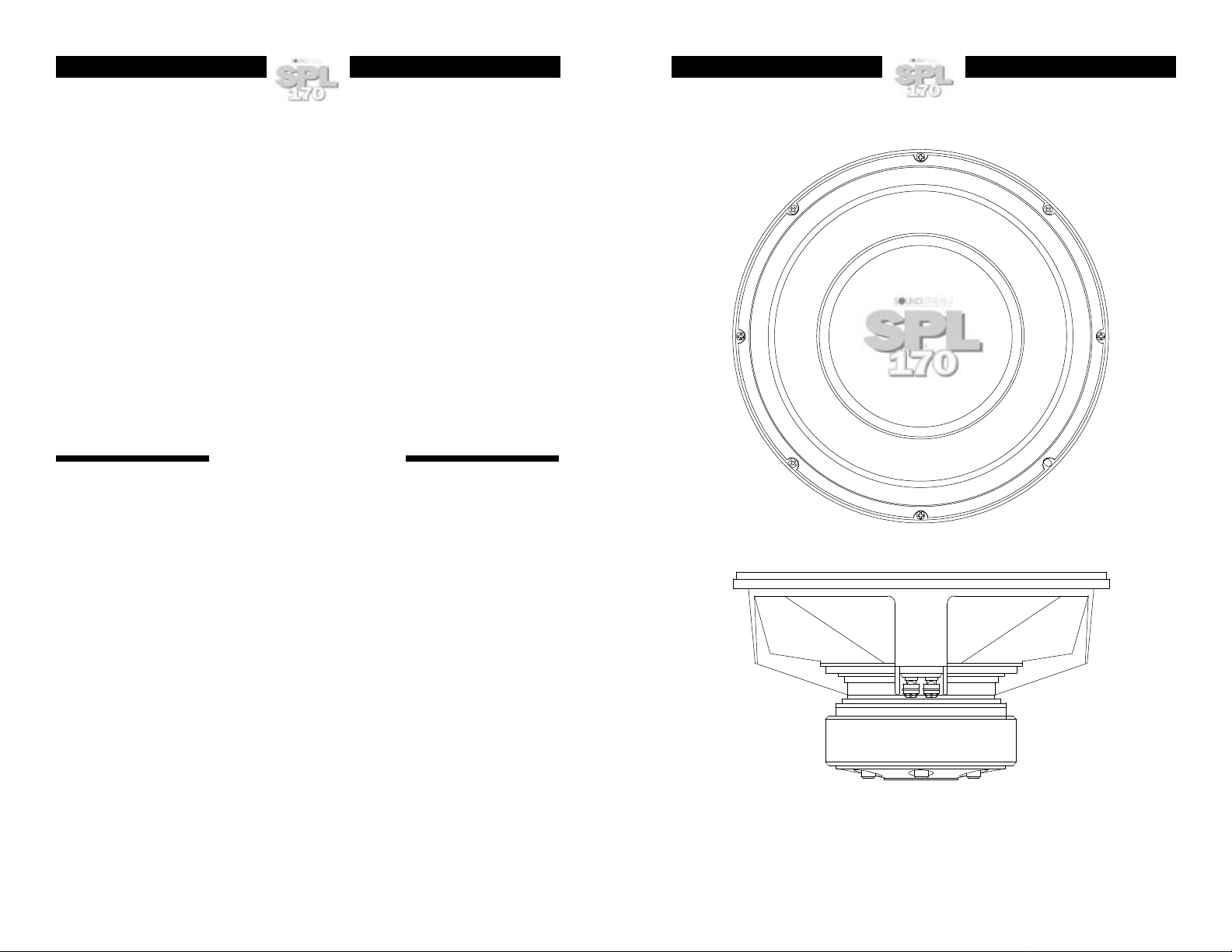
SPL
170
Subwoofer
OWNER'S MANUAL AND
INSTALLATION GUIDE
SOUNDSTREAM TECHNOLOGIES
120 Blue Ravine Road • Folsom • California 95630 USA
tel 916.351.1288 fax 916.351.0414
12
(REV A, 7/22/97)
1
Page 2
CONGRATULATIONS! You have chosen a superior product for
reproducing high "Sound Pressure Levels" in the car. This precision
component, when properly installed, is capable of amazing output
performance. SPL170 woofers are extremely high output speakers with
performance made possible through outstanding design and exceptional
quality in parts and construction.
Should your woofer ever require service or replacement, recording the
information below for your own records will help protect your investment.
Model Number:___________________________________________________________
Serial Number: ___________________________________________________________
Dealer’s Name: __________________________________________________________
Date of Purchase: ________________________________________________________
Installation Shop: _________________________________________________________
Installation Date: _________________________________________________________
DESIGN FEATURES
• New Custom Cone with Large Roll Polyether Surround provides longer excursion and
better control.
• New Revolutionary Computer Numerically Controlled (CNC) Machined Aluminum
Heat Sinks conduct heat from the voice coil to increase power handling.
• New Custom Designed Threaded Input Connectors securely hold 8 gauge cable.
• New Custom Non-Resonant Polypropylene Dust Dome for added structural rigidity
providing solid, well controlled performance.
• Dual Voice Coil Inputs provide increased flexibility in optimizing installations.
• Heavy Cast Aluminum Silver Powder-Coated Basket provides extra rigidity and
damping.
• Ultra-High Power Handling Four Layer Voice Coils with Kapton/Epoxy formers
increase power handling and performance.
• Aerospace Grade Adhesives and Materials insure longevity and high performance.
• CNC Machined Magnet Plates and pole piece precisely focus the magnetic energy for
optimum performance.
• High Emissivity Coatings on all metal plates improve power handling.
• Double Magnet Structures for increased linear strength and throw.
2
11
Page 3

Vented (Continued)
dB
dB
dB
dB
• 4.5 ft
3
@ 25 Hz (Two
4" x 16" ports) -
Designed for
thunderous home
theater bass. Use with
20 Hz high pass filter
for very high power
handling.
105
100
95
90
85
80
75
70
65
60
55
50
10 100 1000
Frequency Hz
Vented (V)
Sealed Bandpass
• Rear = .87 ft
• Front = 1.5 ft
3
sealed
3
@ 75
Hz (Five 4" x 10"
ports) - Very high
output in tiny
enclosure. Great for
SPL vehicles -- 102
dB with 2.83 volts
input! Response
limited to 45 to 100
Hz.
• Rear = 1.2 ft
• Front = 1.5 ft
3
sealed
3
@ 62
Hz (Three 4" x 10"
105
100
95
90
85
80
75
70
65
60
55
50
10 100 1000
105
100
95
90
85
80
75
70
65
60
55
50
10 100 1000
Frequency Hz
Frequency Hz
Sealed
Bandpass
(SBP)
ports) - High output
with response to 35
Hz. Good enclosure
for Rock and Rap
music. 100 dB with
2.83 volts input.
• Rear = 2 ft
• Front = 1.5 ft
3
sealed
3
@ 53
105
100
95
90
85
80
75
70
65
60
55
50
10 100 1000
Frequency Hz
SPECIAL APPLICATION NOTE:
The three enclosures above have been designed with flexibility in mind. One
single enclosure could be constructed to utilize all three response curves. An
adjustable rear volume and port "covers" could allow use of all three
HEAT TRANSFER AND THE
SPL170 -- 30 % BETTER COOLING
One of the major features of the SPL170 is its incorporation of materials and coatings to
provide transfer and elimination of heat.
• When heat is produced in the voice coil, it must be removed. During speaker operation,
heat from the voice coil is radiated and convected into the air and metal in the motor
parts.
• The SPL170 includes unique aluminum plates attached to the top, pole and back plates
to increase heat conduction from the steel parts. Additionally, the steel parts are black
coated to increase their ability to absorb heat from the voice coil.
ALUMINUM
COOLING
PLATES
Tests show almost 30% improved heat transfer from the 170’s voice coil. This produces a
dual benefit to power handling and output:
1. More power handling before voice coil meltdown.
2. Reduced electrical resistance in the voice coil windings resulting in more current flow
capability.
Footnote: The Physics of Heat Transfer
Heat energy, q, radiated between two bodies is determined by the formula:
q
= σεA1F
1-2
1−2(T14−T24
)
An important part of this equation is ε which is the “emissivity”. The larger ε is, the more heat
transfer takes place. ε is largest for a black surface (1.0). That’s why wood stoves and car
radiators are painted black.
10
3
Page 4

385
dB
dB
dB
dB
SPECIFICATIONS & THIELE/SMALL PARAMETERS
Frequency Response (Hz)
Sensitivity (2.83v/1m)
Impedance (nominal Z, ohms)
Rated Program Power, Watts
Fs (Hz)
Qts
Qms
Qes
Efficiency Bandwidth Product (Fs/Qes)
Vas (ft3)
Vas (liters)
Vas (m3)
Cms (um/N)
DCR (ohms)
Levc (mH) @ 1 KHz
BL (Tesla m)
Sd (in2)
Sd (m2)
Sd (cm2)
X max; one way (linear mm)
X max; one way (peak mm)
Vd (linear cm3)
Vd (peak cm3)
Vd (linear m3)
Vd (peak m3)
Mms (grams)
Magnet Assembly (oz)
Magnet Weight (oz)
3
4
0.000847
0.002403
25-500
96 dB
2/8
800
26.2
.371
7.43
.390
67.1
6.36
180
.180
160
2.24
2.475
14.75
131.0
.089
890
9.5
27
847
2403
230
358
118
SUGGESTED ENCLOSURES
Infinite Baffle
• Excellent performance for all types of music at moderate levels
Sealed
3
• 1.0 ft
- Great all
around performing
box. Very small
enclosure. Good for
Rock and Rap.
3
• 2.0 ft
- Slightly deeper
response. Strong
bass at 20 Hz in car.
Good for Rock, Rap
and Jazz.
Vented
3
• 2.0 ft
@ 40 Hz (Two
4" x 13.5" ports) - Very
strong output from 40
Hz to 100 Hz.
Suggest using high
pass filter near 40 Hz
for maximum power
handling and output.
Very small enclosure.
3
• 3.2 ft
@ 28 Hz (Two
4" x 18.5" ports) - Very
strong output to 30 Hz.
Good for home theater
or accurate bass in
100
95
90
85
80
75
70
65
60
55
50
10 100 1000
100
95
90
85
80
75
70
65
60
55
50
10 100 1000
105
100
95
90
85
80
75
70
65
60
55
50
10 100 1000
105
100
95
90
85
80
75
70
65
60
55
50
10 100 1000
Frequency Hz
Frequency Hz
Frequency Hz
Frequency Hz
9
Sealed
Vented (V)
Page 5

BUILDING THE ENCLOSURE
• Determine the dimensions of your enclosure.
• Be certain the box you have designed will fit into the location you have
chosen. Sometimes making a cardboard box with the same outside
dimensions is helpful.
• Use 3/4 inch thick Medium Density Fiberboard (MDF) or High Density
Particleboard. It is preferable to cut the wood with a table saw to ensure
straight, even joints. If a table saw is not available, a circular saw is
acceptable.
• Use a “T” square to verify precise right angle gluing.
• Use a high quality wood glue and air nails or wood screws to assemble the
enclosure. Elmer’s woodworker’s glue and Weldwood work well. To
guarantee an airtight box, seal each inside joint with silicone sealant.
• For Sealed Enclosures, stuff the chamber with 50-75% filling (approximately
1.5 pounds per cubic foot) of fiberglass insulation or Dacron.
• For Vented Enclosures, staple 1 inch thick fiberglass insulation or Dacron to
all walls of the enclosure except the baffle to which the woofer is mounted.
• Use the supplied gasket to seal the woofer in the enclosure and eight(8)
wood screws or T-nuts and bolts. Progressively tighten each of the bolts or
screws to prevent warping the woofer frame.
• Use slide-on connectors to attach speaker wires. Do not solder wires to the
SUGGESTED ENCLOSURES
The following designs include a variety of enclosure sizes and types.
Each design has two frequency response curves; one showing predicted
“In-Car” response, and the other showing “Half-Space Anechoic” (out-of-car)
frequency response. The performance difference between the two curves is a
result of the natural acoustics of an “average” automotive environment. This
“average” transfer function is only an approximation of what you may expect to
see in your car. Every car is different. Each curve was generated using 2.83
Volts across both voice coils in parallel and measured at 1 meter. Also, each
frequency response curve includes a 12 dB/octave low pass at 100 Hz for
sealed and vented enclosures and 200 Hz for bandpass enclosures. The
response curves can help you visualize relative performance differences
between designs. Read through the descriptions given for each enclosure and
select the one that suits your needs.
Remember: all suggested enclosure volumes are Net, and DO NOT include
woofer, port, and bracing displacement!
8
SELECTING AN ENCLOSURE
There are several different enclosure designs for different applications.
The SPL subwoofers work very well in all the following enclosure
designs. It is up to you to select the specific enclosure that will work
the best for your particular application.
Infinite Baffle
Infinite baffle is the simplest type of subwoofer installation. In this type
of installation, the woofer(s) is mounted to a baffle which is then
mounted to either the rear deck or back seat of the vehicle. The best
results are achieved when the trunk area is virtually airtight and
isolated from the passenger compartment.
Pros Cons
• Excellent low frequency extension
• Excellent transient response
• Uses almost no trunk space
Sealed Enclosure
Sealed enclosures are relatively simple to build and install, as all that is
required is an airtight box. The larger the sealed enclosure, the more
the performance resembles that of an infinite baffle installation.
Pros Cons
• Very good low frequency
• Medium efficiency
extension
• Very good transient response
• High power handling
Vented Enclosure
Vented enclosures use a sealed enclosure with a vent or port in the box
which is tuned to resonate at a specific frequency.
Pros Cons
• Good low frequency extension down to the tuning frequency
• High power handling down
to the tuning frequency
• Higher output than sealed
enclosures
• Low power handling
below the tuning frequency
• Almost no output
below the tuning frequency
• Lower power handling
• Low to medium efficiency
Sealed
Vented (V)
5
Page 6

Sealed Bandpass Enclosure
Sealed bandpass enclosures enclose both sides of the woofer(s). An
airtight enclosure is built around the front and back of the woofer and
one chamber is ported to a specific frequency.
Pros Cons
ENCLOSURE VOLUME FLOWCHART
M easure maximum possible dimensions
• High power handling
within the operating
frequencies
• Very high output within
the range of the operating frequencies
• Low power handling
beyond the tuning
frequency
• Poor to moderate
transient response
• Poor low frequency
extension
Sealed
Bandpass
(SBP)
CALCULATING (NET) INTERNAL ENCLOSURE VOLUMES
When constructing any type of enclosure, you must be aware that the
outside dimensions DO NOT represent the true (Net) volume inside.
Such things as woofers, ports, thickness of enclosure material, dividing
walls, and any internal bracing will reduce the total amount of the
actual air space available. The following worksheet has been designed
to provide you with the necessary steps to accurately calculate the
absolute (Net) internal volume of any given enclosure.
Calculating Cylindrical Port Volume
1. Measure the outside diameter of the port and divide by 2 for the
radius.
2. Square the radius and multiply by 3.14 (π) to arrive at outside port
area.
3. Multiply the area by the length of the port inside the enclosure for
the port volume.
M ultiply wall thickness by 2
Subtr act this from each dimension to
arrive at Gross Internal Dimensions
M ultiply LxWxD to arrive at
Gross Inter nal Volume
Deduct Vf (volume of the speaker fram e)
Deduct Vf (volume of the speaker fram e)
from Gross Internal Volume
from Gross Internal Volume
Braces?
No Yes
Calculate br ace volume and deduct
from Gross Internal Volume
You are at Net Internal Volume
in cubic inches (in )
3
To convert to LITERS:
Divide in by 61.03
To convert to CUBIC FEET:
Divide in by 1728
3
3
6
lengthinside
enclosure
outside
diameter
7
 Loading...