

Page 1

MCa300
THREE HUNDRED
MULTIPLE-CHANNEL
AMPLIFIER
WAll
Owner’s Manual
Page 2

MC
0300
Amplifier Owner’s Manual
ThankyouforpurchasingaSoundstreamamplifier.
own one of the finest power amplifiers available, a precision
component capable of
audiophile~quality
performance.
To get the most out of your MC-300. we suggest you
fullyacquarntyourseltwithitscapabilitresanddesign.
retain this manual for future reference.
Soundstream products are the result of American crafts-
manship
MC-300 should deliver many years of pleasure. Should it
and the highest quality control standards; your
Younow
care-
Please
CONTENTS
Wiring Diagram
Design
Installation
Selecting Operating
Optimizing For Speaker Impedance.
Input Connections
Output Connections
Power Connections
Remote Power-on Connection
Powering
Input
Linear Subwoofer Extension
Protection Circuits
Service
Specifications
Features
..........................................
Up the System
Level Adjustment..
...............................................
ever require service or replacement, recording the
tion
below for your own records will help protect your
Investment:
Model Number
Serial
Numbers
Dealer’s Name
Date of Purchase
..................................
.................................
Mode..
................
..............................
...........................
............................
....................
.....................
..............
..............................
.....................
...... ....
~_.
,“xJ’
.2
.3
.3
,4
...
.
.4
.4
.5
~~~~~~~~~~5
.5
.5
.5
.6
.6
...
.6
informs
~~~ ~~~~~~
Page 3
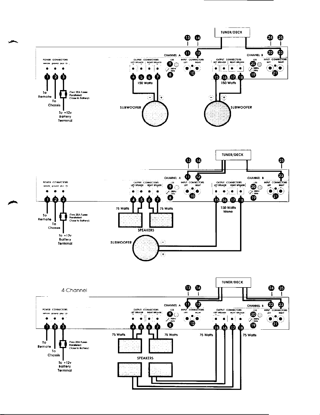
TUNEVDECX
-
Figure 1 Z-Channel Operation
Figure 2
3 Channel Operation
??
w
??
Figure 3
4-Channel
Operation
Page 4

DESIGN FEATURES
INSTALLATION
The MC-300 isconservatively rated at 300 watts
This power can be divided into four channels (4x75 watts),
three channels (2x75 watts.
watts). The design topology utilizes multiple Darlington output devices with a total capability of 1200 watts. With such reserves and no current limiting, the MC-300 operates without
strain even at maximum output. Power, ground, and speaker
cnnnectors are rated to handle up to 60 amps and up to 8
gauge wire.
To provide lull circuit protection necessary for an amplifier
thispowerful,
power supply that works silently and effectively to prevent
nverheating without the need for a fan. Should the
begin to overheat, the power supply slightly reduces output
power, which allows the unit to run
amplifier returns to normal operating temperature. full output
capacity is then restored. The entire process is automatic
and inaudible. In the case of an amplifier malfunction,
secondary thermostats
conventional
on or turn-off thumps. a pair of relays at the outputs allow the
amplifier to fully stabilize before sending
the loudspeakers.
An especially useful feature of the MC-300 IS
woofer Extension (LSE). which compensates
rollofl
of most speakers and extends bass as much as one
full octave. LSE provides a linear boost of 6 dB/octave,
starting at a point which is continuously variable over the
range 35-280 Hz. A subsonic filter attenuates the signal
below 20 Hz.
Orfly prerrfium
film resistors, gold-plated input connectors, and immersible
sealed potentiometers. The case is equipped with generous
heat sinks. Input sensitivity is adjustable to match any tuner!
deck, the MC-300 can even be interfaced with OEM speaker
level signals.
theMC~300incorporatesauniquedual”smat~
manners
parts are used
To prevent potentially damaging
1x150),
WIII
shut down the
111
two channels (2x150
much
the MC.300. such as metal
into4ohms.
ampllfler
cooler. Once the
ampllfler
the
audio signal to
forthe
in a
turn-
Linear Sub-
natural
Proper installation and adjustment will reward you with
reliable operation and optimum performance. Automotive_
sound system installations can be tricky. especially for
timers. For this reason, you may want to consider using a
professional installer who has the tools and, more importantly, the experience, to do the right job. If you decide to
install
your
equipment yourself, we hope that this manual will
serve as a helpful
guide.
firs
LOCATION AND MOUNTING
The first step in irrstallation is thorough planning. Choose the
location for your amplifier carefully. The amplifier should be
located in either the passenger compartment or the trunk,
never in the engine compartment or in any outside location
exposed to din and moisture. Adequate ventilation is important. allow enough space so that air can circulate around the
heat sinks.
Make sure that the installed amplifier will not interfere
normal operation of the car. It is best not to locate the
ampkfier
powersupplycan interfere with AM reception. Your amplifier
should be mounted
four screws provided. USC your amplifier as a template for
making pencil marks where you intend to drill. (Make sure
thatthelocationyouareplanning todrillthroughisfreeofany
obstacles such as wiring or gas tanks.)
It’s a good
thecomponents. If you have a 12.voftpowersource. you can
connect and test all components outside the car. Or, you can
connecttheminsidethevehiclepriortofinal
way, connect the components exactly as you intend to in the
final installation; make all power connections last; test the
system; then disconnect all power until the final installation
is complete.
near your vehicle antenna, since the switching
firrrfly
to your car’s sheet
Idea
to bench test your system before mounting*
metal
mountings
with
with the
Either
WIRING
Determine how your vehicle’s wiring is laid out. Keep all
wiring inside the car. Good standard audio practice suggests
keeping signal wires short and away from wires carrying
power. Wires can be run under carpet. If you drill a new
passage hole through metal, make sure that all burrs have
been filed away to prevent scraping; use grommets where
needed. All wires should be hidden: an exposed wire can
inadvertently be pulled, causing disconnection or shorting.
Wires should never be under tension or subject to moisture.
Use cable ties to bundle excess wire.
3
Page 5

SELECTING OPERATING MODE
The three hundred watts available from the MC-300 can be
-divided
(stereo plus a single mono channels) [Figure
channels (front and rear stereo; or stereo bi-amp) [Figure
To select any of these modes, remove the access plugs on
the bottom of
according to the desired mode of operation.
For two-channel operation. set both switches to MONO.
For three-channel operation, set one switch to STEREO and
ttre
you must connect wires accordingly.
For four-channel operation, set both switches to Sl~tHEO.
into two channels (stereo) [Figure
the
amplifier and set the internal switches
other to MONO. Note carefully which is which, because
I].
threechannels
21,
OPTIMIZING FOR SPEAKER IMPEDANCE
As dellvered from the factory. your MC-300 has been optimized for 4 ohm operation. It is possible to optimize this
amplifierto deliver
loudspeakers. This is done by moans of switches inside the
amplifier.
Remove the plugs on the bottom of the amplIfter marked for
Impedance optimization. Behind the plugs locate the two
switches. one for CHANNELS A and one for CHANNELS
_Sel I!Tse
speclflc patr
the impedance of your speakers, or you are wiring more than
one speaker to a set of
installer
switches separately
of channels
for the best settings.
lmaximum
will
termlnals.
performance into 2.4. or8 ohm
based
on the load which that
be driving. If you are unsure of
consult your dealer or
INPUT CONNECTIONS
Inputs to the
type jacks. The MC.300 achieves a level of performance at
which cable and connector quality is significant: the
your amplifier are gold plated. and we recommend
stream Interconnecting cable or an equivalent premium
cables
In
most cases, the signal source will be the preamp output
jacks of a
connectors other than RCA jacks, in which case you will
need a
If your tuner/deck has speaker outputs and no preamp
outputs. you can use the speaker outputs. Wire an RCA
connector to the end of your tuner/deck’s output wires.
making sure that you maintain consistent polarity in all
channels.
amplifter atlach
tuner!deck.
special
adapter available from your dealer.
by means of standard RCA-
Some tuner/decks
jacks
use
preamp output
or four
31.
B.
on
Sound-
If you have an equalizerorlow-level crossover network(s) for
bi or
tri~amping.
your tuner/deck and your amplifier(s). Refer to the manuals
for these components for further details.
In four channel mode, all four input jacks (11 12.22, and
are active for CHANNEL A left and right, and CHANNEL B
left and right, respectively.
In two CHANNEL mode, use only the
CHANNEL A. and only the “right” jack (23) for CHANNEL
In
threechannel mode,
of main CHANNEL A or CHANNEL B is operating in mono.
and both jacks for the other main channel,
these components will be inserted between
23j
“righf’
jack (12) for
6.
useonlythe”right”jackforwhichever
OUTPUT CONNECTIONS
Use high quality Soundstream speaker cable or an equivalent premium cable for best results.
In four channel mode, all four terminals
for main CHANNELA: and all four terminals (15. 16.
are active for main CHANNEL
In two channel mode, use only the
CHANNEL B. The “+ right”
polarity in this mode.
In three channel mode, use only the
ever of main CHANNEL A or CHANNEL B is operating in
mono, and all four terminals for the other
The
terrrlinals
and loudspeaker wire is coded bycoloror by markings on the
jacket. Be sure to connect the left and right channels with the
same polarity. Loudspeaker manufacturers are not consis-
tent in their polarity markings, so if you have loudspeakers of
different types connected to the same amplifier terminal.
venfy correct polarity by ear. The correct polarity produces
the most bass; incorrect polarity produces less bass and a
strangely dislocated sound image on mono material.
If you have more than one amplifier: for each amplifier and
its loudspeakers, the left and right channels must always be
wired
witl0he
next. correctpolarity may bethesame, or it may be reversed.
This is because of differences in amplifier design. the nature
of crossover filters. and other factors. Again experiment and
verify the correct polarity by ear.
on your loudspeakers are marked for polarity.
same polarity. But from one amplifier to the
13
terrrlinals
(4.5.6.7)
“+”
terminals (15,
(4, 7) have positive
“+“
terminals for which-
tmain
are active
channel.
17;
18)
18)
for
Page 6

POWER CONNECTIONS
Note:
your amplifier can
NegativeGroundefecfricatsysfem. Ifyourcarwasproduced
before
Of electrical system you have before making any
connectfons.
1970. orifyouhaveanydoubts.
on/y
be operated from a 1% volf
mahesureofthe type
If one LED indicator is out, check the internal fuses located
behrnd
the bottom cover of the
power supply
the same value fuse.
fuses~
If any of those are blown replace with
amp.Also
check the interior
_
The MC.300 will draw up to 45 amperes if used to its fullest
capacity~
Current consumption ofthe car’s other accessories. It may be
necessary to upgrade the alternator or to install a separate
battery and battery isolator.
For power wiring. use Soundstream power cable or an
equivalent premium cable. The PLUS 12Vterminal[(3) in the
wiring diagram] should be connected directly to the positive
(+)
iin
have more than one amplifier, each amplifier should be
separately fused.
The GROUND terminal (2) should be connected directly to
the automobile chassis with 8 gauge wire. Make this wire as
short as possible to prevent noise in the system A nearby
bolt can serve as a ground terminal. Make sure that the wire
contacts bare metal, not coated metal
that the ground connection you select have minimal noise
resistance to the battery ground post (a maximum of 0.1
ohm)~
Determine the alternator rating of your car and the
terminal of your car battery. Install two (2) 20 amp fuses
parallel) in the line close to the battery terminal. If you
or
paint. It is important
REMOTE POWER-ON CONNECTION
If your tuner/deck has a remote power,on control wire,
connect it to the REMOTE terminal (1) on your amplifier. This
isacontrol line. notapowerline.
is acceptable.
sosmallwire (1820gauge)
INPUT LEVEL ADJUSTMENT
Input levels are adjusted by means of four independent
controls that are accessible through the heat sink directly
above the input connectors. The controlscan be turned with
a small.
In four channel mode. the left and right halves of CHANNEL
A are set by controls (13) and (14) respectively; the left and
right halves of CHANNEL Bare set by controls (24) and (25).
In twochannel mode,
for CHANNEL A, and only (25) for CHANNEL B.
In three channel mode, use only the “right” control for
whichever of main CHANNEL A or CHANNEL B is operating
In
mono, and both controls for the other main channel.
Depending on how you are using your MC.300 (number of
channels, biamplification. associated equipment, etc.),
ferent factors may apply for optimum gain settings. In general, begin by turning all level controls to minimum (full
counter-clockwise). Turn the system on, and set the volume
control on your tuner/deck at its mid-point. Advance
amplifier input level controls until you have reached a comfortable listening level and both channels are in balance.
No&
cant/y different than the tape output /eve/. Check both
sources. and set /eve/s using the lesser of the outputs
(usuatty
flat~head
with many tuneridecks, the radio output level is
the tape).
screwdriver.
onlythe”right”control(l4) rsoperatfve
dif-
therq
signifi~
If your tuner/deck has no remote power-on control labeled as
such, but has a power antenna control, it may be possible to
wire the power antenna control to the REMOTE terminal.
If your tuner/deck has neither a remote power-on control wire
nor a usable power antenna control; it will be necessary
either to connect the REMOTE terminal to a
which is switched by the ignition key. or to connect the
REMOTE terminal to a constant
on/off switch you install in series with the ignition switch in a
location accessible to the driver. Note:
is used. make sure it is switched off when you leave the
vehicle or when the sound system is not in use.
+12
volt source through an
+12
volt source
/fan
outboardswitch
POWERING UP THE SYSTEM
Once
LED indicators on the MC.300 should now be lit. If they did
not light up, turn thesystem off immediately. Proof wiring and
check for shorts or poor connections.
If wiring is okay, check the relay or fuse in the power line. If
blown, replace it with another identical fuse.
the installation is complete, turn on the system. Both
LINEAR SUBWOOFER EXTENSION (LSE)
The LSE circuit will compensate for the natural
loudspeakers, and can extend deep bass as much as one full
octave. ForCHANNELA.
(9). and the frequency is adjusted by control (8). For
NEL B, LSE is engaged by pressing switch
frequency is adjusted by control (19). If either CHANNEL A
or CHANNEL B is operating in stereo, LSE will be applied to
both left and right.
The control allows for continuously variable adjustment,
over the range from 35 Hz to 280
which LSE beginsits boost. Below thechosenfrequency. the
boost is applied at 6 dB per octave. When properly adjusted,
LSE will “linearize” the low end of the woofer(s) and provide
remarkably smooth and deep bass. A word of caution: small
or inexpensively constructed woofers may be unable
handle the equalization which results from setting the LSE to
above 100 Hz.
LSEisengagedbypressingswitch
Hz;
of the frequency at
rolloff
(20),
of most
CHAN-
and the
to-
_
Page 7

PROTECTION CIRCUITS
SPECIFICATIONS
Your amplifier is protected against both overheating and
-
short circuits. Because of the “soft’ thermal protection (see
the Design Features section on page 3) it is highly unlikely
that the amplifier will shut off because of thermal overload.
If your amplifier shuts down, turn off the system, wait for a
few moments, and turn the system on again.
SERVICE
Your Soundstream amplifier is protected by a limited warranty. Please read the warranty enclosed with the product.
Power output:
2-channel
3-channel
4-channel 75watts continuous per channel
Total Harmonic Distortion <O.l%, 20 Hz 20
Signal-to-Noise Ratio
Damping Factor
IHF Dynamic Headroom 3
Maximum Current Draw 45 amps
Idle Current Draw 2.5 amps
Input Sensitivity 250 mV 2.5 V
LSE .._..................... 35Hz-280Hz.
Dimensions . . . . . . . . . . . . . . . . . . ...14-l/5” W
150 watts continuous per channel
x
2 into 4 or 8 ohms, 20 Hz 20
150 watts continuous mono
into 4 or 8 ohms, 20 Hz - 20
75 watts continuous per channel
x
2 into 2 or 4 ohms, 20 Hz 20
x
4 into 2 or 4 ohms, 20 Hz - 20
at full rated power
into 2, 4 or 8 ohms
~100
._.............__...... >200
with bottom plate
14-l/5”
heat sink
dS
dS
continuously variable
infinitely variable
x 2.3/5”
W x
2-3/Y
kHz
H x 10” D
H x
6-112”
kHz
kHz
kHz
kHz
D
 Loading...