

Page 1
Component Speaker System
OWNER'S MANUAL
Page 2

r
A
Component Speaker System
INTRODUCTION
AND
REGISTRATION
Congratulations on your purchase of the Soundstream EXC Component Speake
System. You now own one of the finest car audio speaker systems available.
s with all high quality car audio components, professional installation is recommended.
Your dealer's knowledge and experience can ensure a problem-free, cosmetically
integrated installation. If you plan on installing the EXC speaker system yourself, please
review this Owner's Manual first before attempting installation. In addition, it's a good
idea to keep the manual for future reference.
EXC Woofer Serial Number ___________________________________
Date of Purchase Date of Installation __________________________
Dealer's Name ___________________________________________
HARDWARE
AND
CONNECTOR
PARTS LIST
Before beginning your installation, please check to see that the number of parts
contained in your box match the list below:
Hardware
Connectors
2 each - flush-mount cups
12 each - 1 1/4" #8 sheet metal screws (for mounting EXC woofers)
2 each - 1/4" 6-32 machine screws (for tweeter flush mount cup spring clips)
4 each - stainless steel tweeter spring clips (for tweeter flush mount cup)
4 each – 1/2” flat head screws (for tweeter surface mounting)
1 each - template set
4 each – 1/4" tab female gold insulated slip-on connectors (for EXC woofers)
16 each – gold spade connectors (for connecting to crossover)
4 each - 1/8” gold round female connectors (for connecting tweeter to speaker wire)
4 each - vinyl insulators (for insulating tweeter speaker connectors)
1
Page 3

r
r
r
r
The EXC Component Speaker System is the result of highly focused engineering effort.
Each element of the EXC system represents several advances in automotive speake
technology. When the EXC project was initiated, the following goals were established:
EXC
DESIGN
Through extensive testing and development, the EXC system has been designed to
provide extremely consistent on and off-axis response in the automobile. Installation
flexibility and ergonomics are enhanced by the mounting versatility of both the EXC
midrange/woofer and the EXC tweeter. Finally, the high output capability and low
frequency extension of the EXC woofers are atypical of most drivers due to the
excursion capabilities of the EXC woofers and the steep crossover slopes of the EXC
system crossovers.
These efforts have resulted in an extremely flexible speaker system that performs
flawlessly in a variety of locations.
• High performance sound reproduction in the automotive environment.
• Ease of installation
• Superb ergonomics and visual appeal.
• High output capability
• Ability to "tailor" sound to each vehicle
FEATURES
EXC Midrange / Woofe
The EXC woofers represent a departure from typical midrange/mid-bass drivers by
combining massive mid-bass and exceptionally smooth midrange.
• Non-resonant Glass resin basket has been designed specifically for extra long
excursion. This results in higher output and extended low frequency response.
• Non-resonant cone geometry yields smooth response and ultra-low distortion.
EXC Soft Dome Neodymium Tweete
The EXC tweeter is an ultra-high performance 1" Neodymium tweeter designed to
deliver outstanding high frequency reproduction
• Fourth-generation Neodymium Magnetic Assembly providing performance comparable or
superior to tweeters three times the size
• A newly improved Textile Dome for a natural, smooth response to 20 kHz.
• Ferrofluid-immersed Voice Coil enhances heat dissipation
EXC Passive Crossover Network
The EXC Passive Crossover represents a new concept in crossover philosophy. The
EXC system crossover consists of high quality, multi-element components with two
switchable functions. A three-position switch controls the tweeter level and a twoposition switch controls the midrange presence. The combination of each allows for a
multitude of control options. Dual inputs allow for multi-channel amp operation of woofe
and tweeter circuits.
• 24 dB/octave Acoustic Summation Crossover Slopes for smooth response.
• Variable Tweeter and Midrange Controls for added flexibility.
• Dual Inputs for multi-amp operation and further flexibility.
• Dynamic Tweeter level Control allows for improved power handling and continuous output.
• Ultra-low DCR Inductors for minimal signal loss (High power Air-core type in woofer path).
• Mylar Film Capacitors to ensure low saturation and accuracy in the high frequencies.
2
Page 4
r
r
LOCATION
AND
MOUNTING
The first step in a successful installation is thorough planning. Choose the location for
your speaker components carefully. Follow these suggestions to ensure proper imaging
and the best performance:
• Select a location where each tweeter and midrange/woofer can be mounted close to
• Choose a location that offers the least amount of sound obstruction.
• Try to mount the components on the same plane.
• Always check behind the chosen mounting locations to make sure that there are no
INSTALLING
THE EXC
TWEETER
The EXC tweeter can be installed in a variety of ways: a simple yet elegant installation
cup is provided for flush mounting; or the tweeter may be easily disassembled fo
custom applications, such as installation in vents, custom painting, or mounting behind a
factory grille. Hardware is provided for each mounting configuration.
each other. A good rule of thumb is a maximum of one foot from midrange/woofer to
tweeter.
obstructions (e.g., trunk springs, gas tank, window track) or wires in the way, as well
as to make sure that there is ample support on which to mount the components.
For surface mounting, locate a flat mounting surface for the EXC tweeter. A direct "on-axis" location is not necessary, as the EXC tweeter provides extraordinary "off-axis"
response.
Flush Mounting
1) Cut a 1 7/8" diameter hole through
the mounting surface. If the surface
is covered with cloth or carpet, be
careful not to tear or pull the
material. Sometimes it is a good
idea to peel the material away and
then trim it by hand.
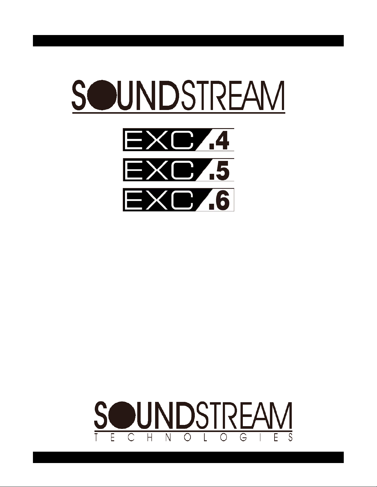
2) Secure the cup in the mounting
cutout by using the spring clips and
screw provided. Slip the spring clips
through the bottom of the cup and
tighten the screw until the cup is
firmly seated. See Figure 1.
3) Once the cup is secure, mount the
tweeter into the cup making sure to
pass the tweeter wires through the
openings in the cup. The tweete
will lock into the cup when turned
clockwise. See Figure 2.
FIGURE 1
FIGURE 2
3
Page 5
r
r
r
r
TWEETER
SURFACE
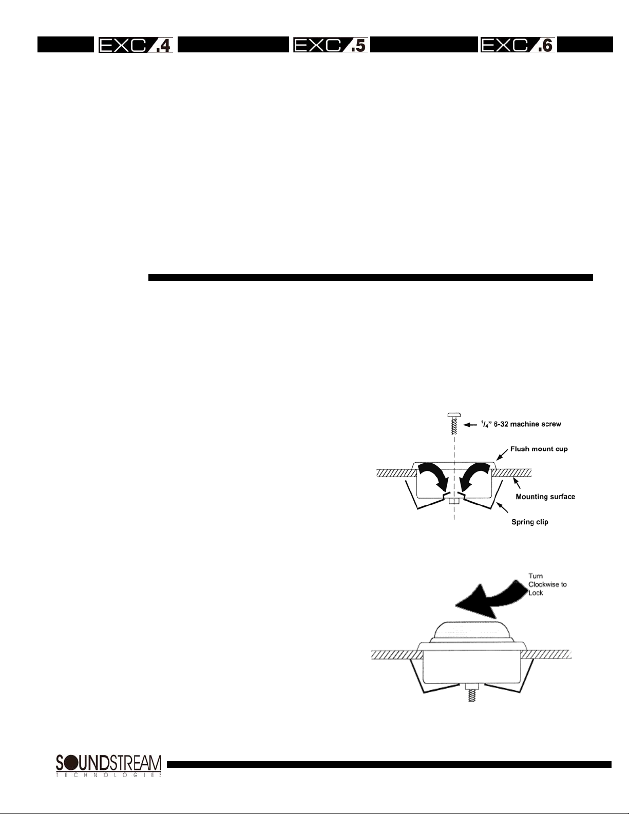
1) Remove the tweeter's plastic backplate
MOUNTING
2) Mark the location in which you are going
3) Mount the backplate with the two 1/2" flat
4) Feed the wires through the holes and
by separating the plate from the tweete
housing with your two thumbnails at one
of the terminal locations, gently prying
the two pieces until they snap apart.
See Figure 3.
to mount the tweeter using the supplied
template and drill holes for each of the
two wires. Also drill small "pilaf' holes fo
the two mounting screws.
head screws. See Figure 4 below.
attach them to the speaker wires going
to the crossover. Position the tweeter
over the backplate and then simply snap
it back on. Be sure to feed the Red wire
through the (+) marked hole.
FIGURE 3
TWEETER
ANGLE
MOUNTING
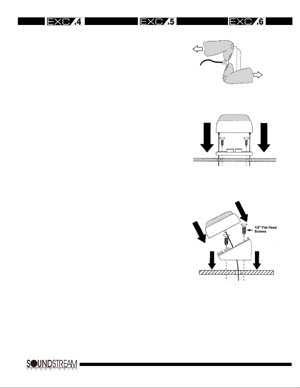
1) Remove and discard the tweeter's plastic
backplate as described above.
2) Drill out the appropriate holes in the back
of the angle mount. Mark the location in
which you are going to mount the tweete
using the supplied template and drill holes
for each of the two wires. Also drill small
"pilot" holes for the two mounting screws.
3) Mount the angle mount backplate with the
two 1/2" flat head screws. See Figure 5.
4) Feed the wires through the holes and
attach them to the speaker wires going to
the crossover. Position the tweeter ove
the backplate and then simply snap it back
on.
FIGURE 4
FIGURE 5
4
Page 6

INSTALLING
THE EXC
MIDRANGEWOOFER
The EXC Midrange/Woofer can be mounted on the front or rear of a panel; gaskets are provided
for both options. The bolt-hole configuration will fit a variety of standard OEM patterns making it
ideal for direct replacement. Best performance is achieved when the speaker is securely mounted
to a door panel or rear deck. There should be no gaps between the speaker and the mounting
surface, as this will impair its low frequency performance. Be certain that both the panel and the
speaker are securely mounted to prevent unwanted vibration.
1. Mark the speaker location by using the template provided.
2. Cut the opening and debur the edges with a file.
3. Hold the speaker in place against the mounting surface and mark the mounting bolt holes.
4. Drill the appropriate size pilot holes for the screws provided.
5. Make all speaker connections prior to mounting the speaker to the panel.
6. Place the Exact woofer into the trim ring, make the speaker wire connections, then install
7. When routing speaker cables to the driver, it is important to form a drip loop in the cable
below the level of the driver to keep water from reaching it. See Figure 6.
the speaker/trim ring assembly to the panel using the screws provided. Affix the grille.
FIGURE 6
5
Page 7

MOUNTING
THE EXC
CROSSOVER
The EXC Passive Crossover can be mounted in virtually any location inside the vehicle.
Be sure not to mount the EXC system crossover outside the vehicle, or in a location
where it may be exposed to dirt or moisture (e.g., the engine compartment, inside a
wheel housing, inside a door, at the bottom of a leaky trunk).
TWEETER
LEVEL
CONTROL
MIDRANGE
LEVEL
CONTROL
DYNAMIC
TWEETER
LEVEL
CONTROL
Tweeter Attenuation
The EXC system has been designed to provide optimum sound in a variety of
installation locations. The provided crossover allows for three positions of tweeter level
control: HIGH, MED and LOW. The LOW position is useful for using the EXC system in
rear-fill applications. A switch under the clear plastic crossover cover sets one of the
three positions. See Figure 7.
Midrange Attenuation
The provided crossover also allows for two positions of midrange level control. A switch
under the clear plastic crossover cover sets one of the two positions - MIDRANGE
PRESENCE -- ON/OFF. The ON position provides increased midrange, a feature useful
for adjusting midrange vocal presence. See Figure 7.
Tweeter Protection Activation
Under high power/high volume conditions, the dynamic tweeter level control (DTLC)
circuit may activate. The purpose of DTLC is to prevent failure of the tweeter by reducing
its output when necessary. Upon activation of the DTLC circuit, there will be an audible
decrease in high frequency output as well as a visual indication from the DTLC light bulb
(see Figure 7). The circuit is self-resetting -- if the DTLC activates, turn the volume down
and normal operation will resume momentarily.
FIGURE 7
6
Page 8

r
WIRING
EXC System Wiring Diagram
Figure 8 shows a diagram illustrating the wiring of the EXC Component Speake
System. It is important to make sure that all connections are in phase; that is positive (+)
is connected to positive (+), and negative (-) is connected to negative (-), since an out-ofphase connection will cause a dislocated image and low bass output. We suggest using
a minimum of 16 gauge (ideally 12 gauge) premium cable. The connectors provided with
this system will accommodate wire from 12 gauge to 16 gauge.
FIGURE 8
7
Page 9

r
A
NOTES ON
BI-AMPING
Bi-Wiring
The EXC component system includes the
EXC passive crossover which is optimized
for the speakers. The EXC crossove
allows for dual amp inputs. See Figure 9.
This feature allows for a 4 channel
amplifier or two 2 channel amplifiers to
power the four individual drivers of an EXC
.6 system. The benefit of this is added
dynamics and level setting flexibility.
head unit's fader control could be used as
a tweeter level control. (See note about
crossover modification for bi-amping.)
Figure 9
8
Page 10

(
NOTES ON
BI-AMPING
CONTD.)
Bi-Amping
True bi-amping can also be accomplished with an
external electronic crossover. See Figure 10.
Even greater dynamics can be realized with
bandwidth-limited amplifiers. If your decide to biamp, please follow the recommendations below:
1) Use at least a 12dB/octave high pass filter no
2) Use at least a 12dB/octave low pass filter no
This "staggered" active arrangement allows one
full octave of bandwidth between the amp's active
range and the speaker's passive range. This
stagger allows the purpose designed passive
network to operate as intended. You will gain the
benefit of dedicated amplifiers and retain the
sound quality designed into the passive crossover.
higher than 1500 Hz on the tweeters.
lower than 6000 Hz on the woofers.
Figure 10 Active/Passive
Bi-Amp
9
Page 11

SPECIFICATIONS
EXC System Specifications
Frequency Response
Sensitivity 90 dB SPL at
Continuous Power Handling 60 watts 70 watts 80 watts
Peak Program Power Handling 120 watts 140 watts 160 watts
Nominal Impedance
Crossover Slope Rate 24 dB/octave ASC 24 dB/octave ASC 24 dB/octave ASC
Crossover Dimensions 3.25" (W) x 15" (H) x
70 Hz - 20,000 Hz
+/-3dB
1 meter (2.83v)
96 dB SPL at
.5 meter (2.83v)
3Ω 3Ω 3Ω
5.125" (D)
60 Hz - 20,000 Hz
+/-3dB
91 dB SPL at
1 meter (2.83v)
97 dB SPL at
.5 meter (2.83v)
3.25" (W) x 15" (H) x
5.125" (D)
50 Hz - 20,000 Hz
+/-3dB
92 dB SPL at
1 meter (2.83v)
98 dB SPL at
.5 meter (2.83v)
3.25" (W) x 15" (H) x
5.125" (D)
EXC Midrange/Woofer
Frequency Response 70 Hz - 7,000 Hz
+/-3dB
Continuous Power Handling 60 watts with
EXC .4 Crossover
60 Hz - 7,000 Hz
+/-3dB
70 watts with
EXC .5 Crossover
50 Hz - 7,000 Hz
+/-3dB
80 watts with
EXC .6 Crossover
Peak Program Power Handling 120 watts with
EXC .4 Crossover
Sensitivity 90 dB SPL at
1 meter (2.83v)
Nominal Impedance
3Ω 3Ω 3Ω
140 watts with
EXC .5 Crossover
91 dB SPL at
1 meter (2.83v)
160 watts with
EXC .6 Crossover
92 dB SPL at
1 meter (2.83v)
Nominal Driver Diameter 4 ¼" 5 1/4" 6 1/2"
Mounting Cut-Out Diameter 3 9/16" 4 13/16" 5 3/4"
Mounting Depth 2 1/8" 2 1/4" 2 11/16"
EXC Soft Dome Neodymium Tweeter
Frequency Response 2,500 Hz - 20,000
Hz +/-3dB
Sensitivity 92 dB SPL at 1
Nominal Impedance
meter (2.83v)
4Ω
Nominal Tweeter Diameter 1"
Mounting Cut-Out Diameter 1 7I8"
10
Page 12

1550 Maple Ave., Montebello, CA 90640 USA
Phone: (323)724-4600 Fax: (323)722-8125
www.soundstream.com
 Loading...