

Page 1
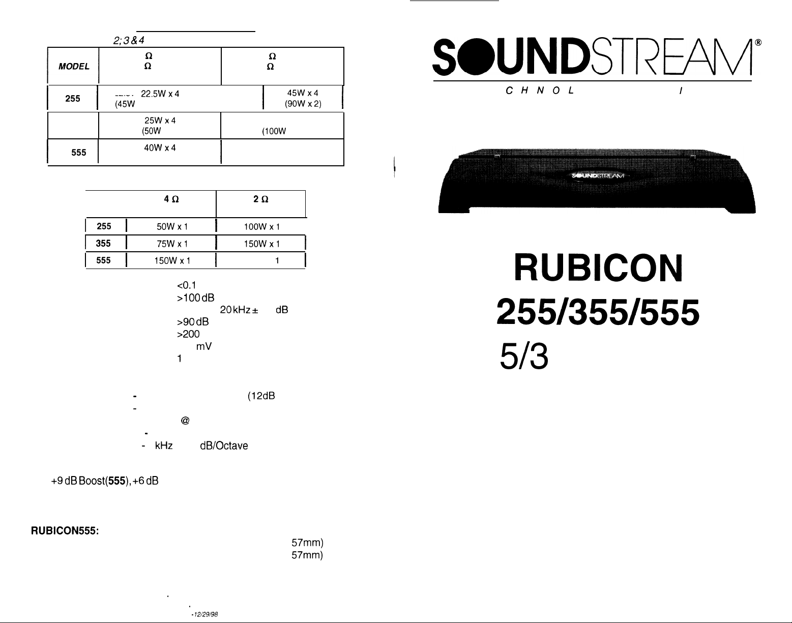
SPECIFICATIONS
Channels I &
1
255 1 (4kW x2)
355
I
555
THD
Signal to Noise
Frequency Response
Stereo Separation
Damping
Input Sensitivity
Input Impedance
2; 3 & 4
4 a Stereo
(8
i2
Bridged)
(12.5 Vdc)
225Wx4
25Wx4
(5OW
x 2)
4owx4
I
Subwoofer Channel
MODEL
I I
I
255
I
355
I
555
(80W x 2)
4Q
(12.5 Vdc) (14.4 Vdc)
I
I
I
5OWxl
75Wxl
15OWxl
2
Q
Stereo
(4
Q
Bridged)
(14.4 Vdc)
1
5ow x4
(IOOW
80W x4
(160W
2t2
100wx1
I
15OWxl
I
250W x
I
co.1
%
>I00 dB
20 Hz to 20 kHz sf 0.5 dB
>90 dB
900
200 mV to 5.0 Volts
1
Ok Ohms
1
$“,“x:,
x 2)
x 2)
Crossover Specifications
Low Pass:
High Pass:
Band Pass (555): 50 Hz - 500 Hz at 12 dB/Octave (Mid-Bass)
55 Hz - 220 Hz at 24 dB/Octave
50 Hz - 500 Hz at 12 dB/Octave
(Removable SIP @ 150 Hz on 255)
50 Hz - 4
kHz
at 12 dB/Octave (Mid)
(12dB
on 255)
SWNDSTREAI’V
T E C H N 0
j
I
I
I
RUBICON
5/3
Power Amplifiers
L
0 G
I
E S
Channel
Hawkins Bass Control
0 to +9 dB
(Hawkins Bass Control “IN”)
Boost(555), +6 dB
(255,355); Boost Frequency = 45 Hz
Sub Sonic filter frequency = 13 Hz
Dimensions (W x D x H)
RUBICON555:
RUBICON355: 13.0” X 9.8” X 2.25” (330mm X 250mm X
RUBICON255:
15.0” X 9.8” X 2.25” (381 mm X 250mm X 57mm)
11 .O” X 9.8” X
WWW.SOUNDSTREAM.COM
Folsom - California 95630 USA
ph 916.351.1288 . fax 916.351.0414
2.25”
(280mm X 250mm X 57mm)
rev A - 12/29/98
Owner’s Manual
and
Installation Guide
57mm)
Page 2
Congratulations!
You now own a Soundstream
uncompromising design and engineering philosophy. Your Soundstream
RUBICON
amplifier will outperform any other amplifier in the world.
RUBICON
amplifier,
the
product of an
Design Features
Table of Contents
.......................................................
p4-5
To maximize the performance of your system, we recommend that you
thoroughly acquaint yourself with its capabilites and features. Please
retain this manual and your sales receipt for future reference.
Soundstream amplifiers are the result of American innovation and
craftmanship
installed, they will provide you with many years of listening pleasure.
Should your amplifier ever need service or replacement due to theft,
please record the following information which will help protect your
investment.
Model and Serial #
Dealer’s Name
Date of Purchase
Installation Shop
Installation Date
with the highest quality control standards. When properly
Rubicon
Rubicon
Rubicon
Crossover Adjustments
Hawkins Bass
Amplifier Diagram
Amplifier Diagram
Amplifier Diagram
............................................
ControlTM
Theory and Use
.................................
.................................
.................................
Installation: Speaker Output Modes
Installation: Wiring
lnstal
lation: Mounting
lnstal
lation:
Level Setting and Front Spoiler..
...................................................
..............................................
................ p 14
........................
..........
~6-7
p8-9
plO-11
p 12-13
P
15
P 16
P
17
p 18
f
Prolonged listening at
Even though your
better than anything you’ve ever heard, exercise caution to
prevenf
hearing damage.
CAUTION!
high
levels may result in hearing loss.
new
Soundstream
Rubiwn amplifier sounds
Sample System Diagrams
. . . . . . . . . . . . . . . . . . . . . . . . . . . . . . . . . . . . . . . .
p 19-26
Protection Circuitry, Service and Troubleshooting . . . p 27
Specifications
. . . . . . . . . . . . . . . . . . . . . . . . . . . . . . . . . . . . . . . . . . . . . . . . . . . . . . . . . . .
3
P 28
Page 3
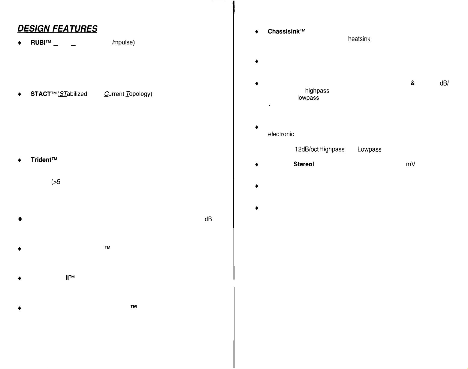
RUBITM
supply topology eliminates “power sags” during low frequency reproduction by rapidly increasing the duty cycle, stabilizing the power supply and allowing it to deliver the power required when reproducing low
frequencies. Also, greater reserve gate power is stored for low voltage situations that occur during extreme conditions.
STACTTM (STabilized
ply stress by 50%. Typical designs degrade the stereo image due to
phase reversal of even-order harmonic distortion that occurs between
the inverted channels. In the STACT design, inversion is done at the
power amplifier drive stage. Since the fully symmetrical power amplifier produces no even-harmonic distortion itself and all preamplifier
circuitry is run completely in-phase, no even harmonic distortion phase
reversal occurs.
(Rapid-Use Branched
-
-
Apex
Qrrent _Topology)
jmpulse)
This new proprietary power
Reduces power sup-
ChassisinkTM
tween the circuit board and the heatsink to provide cool efficient amplifier operation.
Differentially Balance RCA Input
in the audio path.
Continuously Variable Crossover Networks (355 & 555):
Octave 2-way
dB/Octave
-
12 dB/Octave 3-way crossover which can be selected for mid-bass
(65 to 500 Hz) or midrange (65 to 4,000 Hz) operation.
Built-in Staggered S.I.P. Crossover Network (255)
electronic
channels 1-4 of the amplifier and send low pass to channel 5 of the
amplifier.
All transistors are ideally located and sandwiched be-
eliminates ground loop related noise
12 dB/
highpass
lowpass
crossover is designed to send high pass information to
12dB/oct Highpass
crossover, variable from 65 to 220 Hz and 24
crossovers variable from 30 to 120 Hz. 555 on/y
Built-in two-way
and
Lowpass
crossovers.
TridentTM
1. Output protection against short circuits or improper loads.
2.
Ground fault detection: Shuts down the amplifier when a significant
voltage
and battery ground.
3. Thermal Protection: Puts the amplifier into thermal rollback or shuts
the amplifier down in extreme thermal conditions.
Hawkins Bass Control
at 45 Hz) and routes otherwise wasted amplifier power back to the
audible bandwidth.
Harmonic Bass Alignment
are critically aligned to fundamental peaks at low frequencies. This
produces tighter, more accurate bass reproduction.
Drive Delay
power supply eliminating turn-on pops. Turn off process is reversed:
Amplifier section turns off first, followed by the power supply.
Dynamically Optimized
uted between primary and secondary power supplies, providing
dynamics and improved RF filtering.
Protection
(~5
Volts) fluctuation occurs between electrical (turn-on lead)
llTM
Topology
provides a focused subwoofer boost (O-9
Amplifier section powers up 2 to 3 seconds after the
Power Grid
provides three types of protection:
TM
The 2nd and 3rd order harmonic peaks
Power grid is evenly distrib-
TM
dB
greater
Flexible
sensitivity.
Symmetrical Discrete Balanced Class A Drive Boards Auto-ad-
just for linear performance while driving low impedance loads.
Removable Front Spoiler allows for stealth installation of RCA,
Speaker and Power wiring.
Stereo1
Input Level Control allows 200 mV to 5 V input
4
Page 4
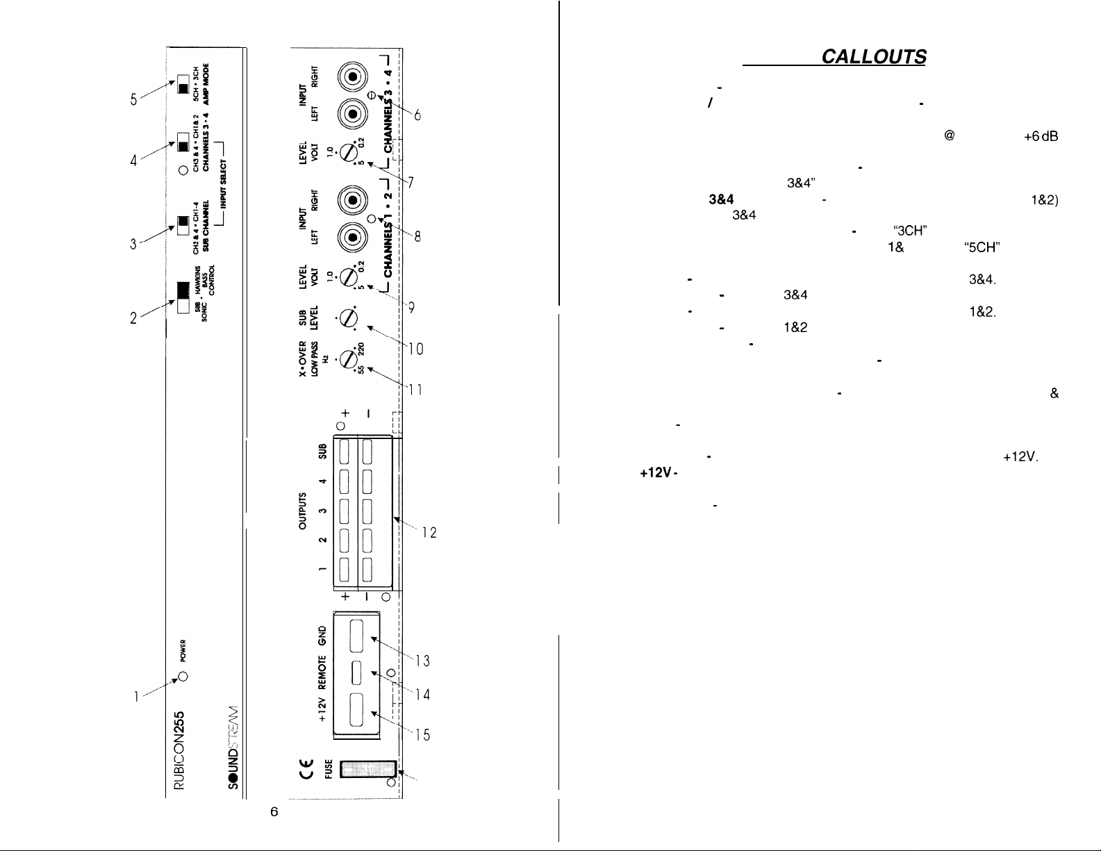
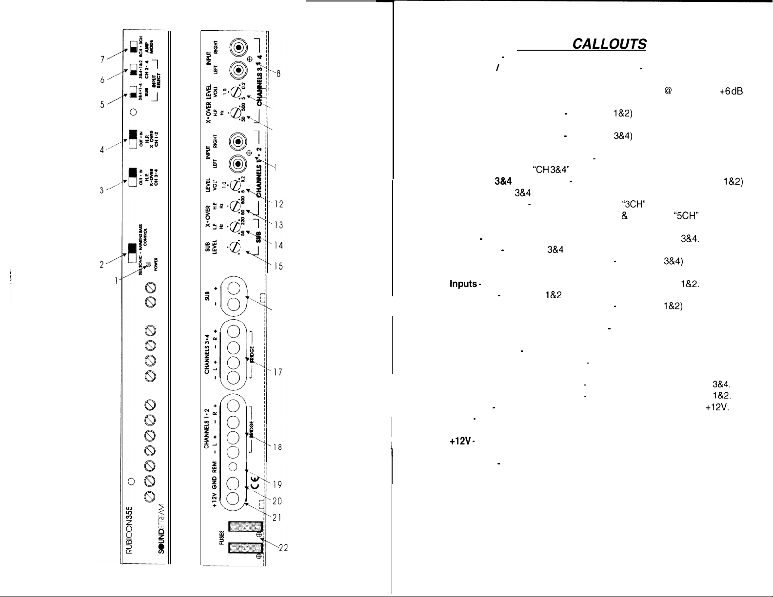
KEY TO
1.
Power LED
2.
Subsonic / Hawkins Bass Control Switch
engage the Sub Sonic filter at 13 Hz. Select “HAWKINS BASS CONTROL”
to engage the subwoofer channel’s high pass filter @I 45 Hz with +6
boost for optimum bass.
3.
Subwoofer Channel Input Select
fading bass control, “CH 3&4” for front to rear fading bass control.
4.
Channels
or external (CH
5.
Amp Mode Switch (Channels 1-4)
in 3 channel operation (use input channels
output in 5 channel operation.
6.
Inputs
7.
Input Level
8.
ltiputs
9.
Input Level
10.
Sub Input Level
11.
Low Pass Filter Control Adjustment
frequency control for the internal low pass filter.
12.
Speaker Connection Terminal
Subwoofer Channel.
13.
GND - Main ground connection.
hicle.
14.
REMOTE
15.
+12V -
tive terminal.
Main Fuse
16.
-
Indicates amplifier power.
3&4
Input Select
38~4
local RCA inputs).
-
Right and left channel RCA inputs for channels
-
Channels
-
Right and left channel RCA inputs for channels l&2.
-
Channels
-
Subwoofer channel input level control.
-
Remote turn-on input from the head unit. Accepts +12V.
Connected to a fuse or circuit breaker, then to the battery’s posi-
-
Main power supply fuse.
CALLOUTS
-
Select “SUB SONIC” to
-
Selectable inputs; “CH l-4” for non-
-
Selectable inputs from internal (CH
-
Select “3CH” for bridged mono output
1 &
2). Select “5CH” for stereo
3&4
input level control.
l&2
input level control.
-
(Subwoofer Channel) crossover
-
Speaker connections for CH l-4
Bolt to a clean chassis point in the ve-
3&4.
dB
l&2)
&
‘.
‘.
16
Page 5
9
10
,-l
1
16
KEY TO
1.
Power LED - Indicates amplifier power.
2.
Subsonic / Hawkins Bass Control Switch - Select “SUB SONIC” to
engage the Sub Sonic filter at
to engage the subwoofer channel’s high pass filter @ 45 Hz with +6
boost for optimum bass.
3.
High Pass XOVER Switch - (Channels l&Z) Select “IN” for use with the
internal crossover or “OUT” for use with external crossover.
4.
High Pass XOVER Switch - (Channels
internal crossover or “OUT” for use with external crossover.
Subwoofer Channel Input Select - Selectable inputs; “CH 1-4” for non-
5.
fading bass control,
6.
Channels
or external (CH
7.
Amp Mode Switch - (Channels 1-4) Select
in 3 channel operation (use channels 1 & 2). Select
output in 5 channel operation.
8.
Inputs - Right and left channel RCA inputs for channels
9.
Input Level - Channels
10.
High Pass Filter Control Adjustment - (Channels
quency control for the internal high pass filter.
11.
tnputs -
Input Level
12.
13.
High Pass Filter Control Adjustment - (Channels
quency control for the internal high pass filter.
14.
Low Pass Filter Control Adjustment - (Subwoofer Channel) crossover
frequency control for the internal low pass filter.
15.
Sub Input Level - Subwoofer channel input level control.
Speaker Connection Terminal
16.
Channel.
17.
Speaker Connection Terminal - Speaker connections for Ch’s
Speaker Connection Terminal - Speaker connections for Ch’s
18.
19.
REMOTE - Remote turn-on input from the head unit. Accepts
20.
GND - Main ground connection.
hicle.
21.
+12V -
tive terminal.
22.
Main Fuse - Main power supply fuses.
3814
Right and left channel RCA inputs for channels
-
Channels
Connected to a fuse or circuit breaker, then to the battery’s posi-
“CH 3&4”
Input Select - Selectable inputs from internal (CH
3&4
local RCA inputs).
CALLOUTS
13
Hz. Select “HAWKINS BASS CONTROL”
3&4)
Select “IN” for use with the
for rear fading bass control.
“3CH”
3&4
input level control.
l&2
input level control.
-
Speaker connections for Subwoofer
Bolt to a clean chassis point in the ve-
for bridged mono output
“5CH”
for stereo
3&4.
3&4)
crossover fre-
l&2.
l&2)
crossover fre-
dB
l&2)
3&4.
l&2.
+12V.
8
Page 6

.______---
r-k
/
sl3Nkviqq- 2
---
---
----
/
------
•/=Q-~-~f-p~
---------
I
,
----
------
I
---___----_~-----
,
*
’
,rr
I,
----
J
/
--
L--J
---
-_
-__
c
_-~~~~~~--__----------~_-----_~~
co
ii
-_--_----------------
rJ
0
ti”S
NOIlVUMO
+
t
1 4 4
-HNNVH3-S
f
z
1
wvuf)tna
NoKHNNcn
WWV3dS
.-&03aq
‘APO
/
,’
,,‘-
2
!qndu/
‘8
_
3yoo! Ino
c
H3
-
p
04
78
-.__
&
Cndw
awl
HZ
----__
---__
---_____
--
-.__
-----____
a
----_
-----.______----
___------
_---
__._A_
-------
-----
-
---_
_
-I_
---_
-1
-
‘._
--.
.
.._
“-\_.
3~0~321
aw
kut+
@
._
---_.
__--
___--
__e
----
0
__--
--
-.
--
---.
‘.
Page 7

The
RUBICON
over, with RCA outputs
external electronic crossover is necessary. However, if you do desire to use an
external crossover you still have that option. The high and low pass portions of
the crossover can be set independently of one another.
In many car audio installations, there is a tendency for a “midbass boom.” Because of their interior dimensions, most cars will resonate or ring at these midbass
frequencies. If we design the system so there is reduced output in this region, the
final response is very smooth and natural sounding. The high pass crossover is
independently variable from 50 to 500 Hz at 12 dB/Octave (Removable SIP
150Hz
on RUBICON255. See
pass crossover is independently variable from 55 to 220 Hz at 24 dB/Octave.
amplifiers incorporate an on-board staggered electronic cross-
(RUBICON
next
only) to drive an external amplifier. No
page for different frequencies)! and the low
@
31WAY (555
ONLY)
MIDBASS/MIDRANGE BAND PASS
The
RUBICON
figuration. In the three way mode, you can tri-amplify with “active”
midrange to maximize control over individual drivers. The
a low pass and high pass filter, which work independent of one another, to
drive the midrange or midbass speakers.
39WAY
can be operated in midrange or midbass “band pass” con-
bandpass
12 dB!Octave
24 dB/Octave
midbass
includes
or
For initial crossover setup, try setting the low pass filter to approximately 60 Hz,
and the high pass filter to approximately 150 Hz. Change the crossover points to
accommodate a good mixture of frequency response, power handling, and per-
sonal preference.
12 dB/Octave High Pass
29WAY
-xx
,
SIP CROSSOVER
(255
ONLY)
The
RUBICON
(Series In-line Package resistor network) I If you want to use
a frequency other than the factory pre-set frequencies follow
the chart to the left or the formula below to select your own
comes with a
150Hz
High Pass S.I.P.
.
12
Page 8

Hawkins Bass Control - Theorv and Use
Hawkins Bass Control (variable) is a unique subwoofer control
circuit included with the Soundstream
is capable of removing subsonic energy in program material below 45 Hz at 12 dB/Octave, while boosting subwoofer frequencies. The circuit consists of two controls. One engages a subsonic High Pass filter at
of boost (0 to +9
dB)
(fixed at
45
Hz, and the other adjusts the
+6dB
The Boost control adjusts the amount of level applied at the
frequency, and is adjustable from 0 to +9 dB (see figure 2). When
the boost is set to 0, Hawkins Bass Control acts as a sub sonic
filter only. The simple act of removing potentially harmful low fre-
quencies can improve system output by as much as 3
Application
Subwoofer drivers in general have excellent power handling characteristics over
their operational bandwidth. This bandwidth
is determined by many factors, including dB-l~
driver design and enclosure type. It is possible to overdrive any subwoofer driver by
sending powerful signals outside of its op-
erational bandwidth. These potentially dam-
aging signals can be removed by adding a
subsonic filter. Figure 3 shows the effectiveness of the Hawkins Bass Control on
woofer excursion in a vented enclosure. The woofer travels 7.5 mm at 10 Hz. With
Hawkins Bass Control properly adjusted, this excursion can be reduced to less
than 1 mm. This is of great benefit to lowering woofer distortion and increasing
output.
Adjustment (555 on/y)
An easy method of optimizing your existing subwoofer enclosure with Hawkins
Bass Control is as follows:
1.
Adjust the boost control to full counter
clock-wise (0) position.
2. Set the bass control switch to
“HAWKINS BASS CONTROL”.
3.
Play
moderatetoloud bass
4.
Adjust the boost (Q) control until you
reach the desired level.
RUBICON
for the
material.
amplifier. It
amount
RUBCON &
dB.
lo
5
.t
15
-*Or
-*’
:recuency
-3010
FIG. 2 VARIABLE BOOST
10
c
0
-5
dB
-10
,5
20.
-301 0
Frequancy
FIG. 3 Limited Excursion
set
!
f
!
I
!
HAWKINS
BOCST
Q
.
0
c’ ;
FIG,
I
. 1
100
1
355).
(HZI 50
(Hz) 50 100 230
INSTALLATION STEP 1
SELECTING THE SPEAKER OUTPUT MODE
Channels 1 through 4 of the
to operate in any one of the following modes:
5CH (Stereo /Mixed Mono): Use this mode for 5 channel stereo operation (all
channels) or for Mixed Mono operation_
3CH
(Bridged
Mono): Use this mode to bridge channels l&2 and
3 channel operation.
Please follow the wiring schemes below for the correct operation:
,
hi
I
t
I
1
260
.
BRlDGi5-MoNO
-
L+
__~ ____._- __.____
RUBICON255,
/’
-
R+
\
355 & 555 amplifiers have the ability
3&4
outputs for
,;
1
-
-rTl \.
.__
5CH
..__
__,’
---
-R+
1
/’
--__
‘~
-
L+
/---------
‘\
STEREO
---
With Soundstream’s Hawkins Bass Control, the boost and frequency control can
provide the “tailoring” needed for any type of “assisted” design and any woofer in
any type of installation.
14
15
Page 9

f
INSTALLATION STEP
2 ]
POWER AND GROUND
To ensure maximum output from your
loss power and ground cables and connections. The
accept up to 4 or 8 gauge power and ground cables. Determine from the chart
below the minimum and maximum gauge power and ground wire for your applica-
tion_
up to
(RUBICON
1
RUBICO/v355
mi[
1 8 or IO gauge
8 or 10 gauge
1
4 or8 gauge 1 4 gauge only
RUBICON
10’
amplifier, use high quality,
1
RUBICON
up to
8 gauge only
8 gauge only
amplifiers will
20’
low-
/
CIRCUIT BREAKERS AND FUSES
EXTERNAL
Like all audio components, the
A fuse or circuit breaker must be located within 18” of the
a fire in the event of a shorted cable. See the chart below to determine the correct
fuse value.
RUBICON
amplifier must be fused near the battery.
batterv.
This will prevent
INTERNAL
The
RUBICON255,
the event of blown power supply fuses, replace with the correct value fuse found in
the chart below. Never replace the fuse with a higher value than what is sup-
plied. This may result in amplifier damage and will void the warranty!
RUBICON255,355 &
IRuaconr255
RUB/CO/V355
RUBICON555
355 81 555 amplifier are fused with automotive-type fuses. In
555 Amplifier Fuse Values
Amplifier Fuse
1
30 amp automotive
(2) 20 amp automotive
(2) 30 amp automotive
Battery Fuse / Circuit Breaker
1
40 amp
50 amp
80 amp
REMOTE TURN-ON
Connect the “Remote” line to the turn-on lead from the source unit. When
Volts is received, the amplifier will turn on.
+12
SIGNAL CABLE
Use a high quality cable that will be easy to install and has minimal signal loss to
guarantee optimum performance.
(
INSTALLATION STEP 3
INSTALLATION AND MOUNTING
AMPLIFIER LOCA T/ON
The
RUBICON
heat sink, and a unique Chassisink construction to maintain lower operating temperatures. Additional cooling may be required if the amplifier is located in a tightly
confied
area or when driving especially low impedance loads at extremely high
levels.
When mounting the amplifier, it should be securely mounted to either a panel in the
vehicle or an amp board or rack that is securely mounted to the vehicle. The
mounting location should be either in the passenger compartment or in the trunk of
the vehicle, away from moisture, stray or moving objects, and major electrical com-
ponents. To provide adequate ventilation, mount the amplifier so that there are at
least two inches of freely circulating air above and to the sides of it.
MOUNTING THE AMPLIFIER
a.
Using the amplifier as a template, mark the holes on the mounting surface.
b.
Remove the amplifier and drill the holes for the mounting screws.
C.
Secure the amplifier to the mounting surface using the supplied hardware.
WIRING
Run and connect the audio signal and remote turn-on cables to the amplifier
a.
from the source unit.
b.
Carefully run the positive cable from the amplifier to a fuse or circuit breaker
within
C.
Connect the fuse or circuit breaker lead to the battery. Leave the circuit
breaker off or the fuse out until everything is bolted down.
d.
Secure the ground cable to a solid chassis ground on the vehicle. It may be
necessary to sand paint down to raw metal for a good connection.
e.
Double check each and every connection!
f.
Reconnect the fuse or circuit breaker.
POWER UP
Power up the system and look at the Power LED; there may be a 2-3 second delay
from the time the source unit
on, which is normal. Once the amplifer LED is on and the source unit is playing,
you should have sound coming from the speakers.
amplifier employs highly efficient circuitry, a custom-engineered
18”
of the battery.
is
turned on to the time that the LED on the amp turns
SPEAKER CABLE
The
RUBICON
quality, flexible, multi-strand cable for best performance and longevity.
amplifiers will accept up to 8 gauge speaker cable. Use a high
16
17
Page 10

(
INSTALLATION STEP
LEVEL SEmlNG
4)
2-way
4 channels of
4 channels of input
front/rear fade with constant level bass
2-way
high pass, (rear de-emphasis engaged on
subwoofer channel in low pass
555)
The input levels are adjusted by means of the input level controls located on the
front of the amplifier. This is a unique dual-stage circuit that adjusts both level and
gain. This topology maintains better S/N Ratio even when using sources with
minimal output.
In the ideal situation, all components in the audio system reach maximum undistorted
output at the same time. If you send a distorted signal to an amplifier, it is simply
going to amplify distorted information. The same holds true if an outboard processor or crossover begins to distort before you have maximum output from the ampli-
fier. By setting all components to reach clipping at the same time, you can maxi-
mize the output of your system.
For the
RUBICON
amplifier, follow these steps for
setting the input levels:
Turn the amplifier’s input levels to minimum position (counter-clockwise)
1.
Set the source unit volume to approximately
2.
While playing dynamic source material, slowly increase the amplifiers’ input
3.
3/4
of full volume.
level until a near maximum undistorted level is heard in the system.
FRONT SPOILER
I
Once the amplifier is installed and the
position, and secure it using the suppl
proper levels set, place the front spoi
ied
hardware.
er in
______________-...-_-~-________________---.---_--___-------~.~____--------_~____-----~-~~~~___-------.-..__.
_
RUBiCGfu255 0 -
CC
tl2V
REMOTE
-L+
,
\
\
I
I
,
,
+12VWDREM
FUSE
GND
_.
cm
.
r-a
cnse4*cx14
SLN-
0 c.
cH2~4.atI~2
cnAnmu2*4
-
_
-.
m ] !
CHANNELS394
L*
-R+
-
Page 11

4
channels of
SOUNDI-
G?Yh”
t
TOP VIEW
CC
+12V
FUSE
FRONT VIEW
SAMPLE
2-way
REMOTE GND
‘I
SY$TEllU #2
2
channels of
high pass, (rear de-emphasis engaged on
subwoofer channel
-All
input
in low
Mode/s
pass
LML
VOLT lm RiGHI
1.0
IwU7
+yANNE(b
-_--
555)
----
1 I
RADIO
3 l 4
__-__-_-_
SAMPLE SYSTEM #3 -
/2ss
ag55..
4 channels of input
3 channel operation with satellite to subwoofer fading
2 channels of bridged
TOP V
EW
t12V REMOTE GND
J
-
FRONT VIEW
2-way
OUTPUTS
12 3
high pass, subwooferchannel in low pass
X*OVER BUD
4SU8
lcmms LEVEL
Hz
+12V
GND REM - L
: /
i
I
___ __.~~.
:
BOTTOM VIEW
CHANNELS 1 l 2
-R+
+
- -
CHANNELS S-4
-L+
e
CHANNELS
-L*
-R+
SUB
F-------Y
-R+ -+
3=4
/
TOP VIEW
0
X*WER SUB
KJOST
IWWHS Hi
X-OVER
, RADIO
LEVEL
i
RUBICON
/
TOP VIEW
BdPUl
I
__________- __-__-____
~_--
+12VWDREM - 1 +
cHANNHs1*2
00y9@@@
CC
-7
y/F
-L___________
f--_:
-----------
CHANNEW
-R+
-L+
3.4
-R+
-+
)(ooo$@$
---___ ~~~~~----~-.------
,--:
sm
I-.
111
__---
3lJB
XaWER LEVEL Epvl
LEVEL LI!
-
H.R
VMT
LEFf
RIGHT
X*OVERl.ML
H.R wll LEFI Rlwr
!Al+
LP
MOWlNPUlS X*OVER
LML
I 2
I.0
LEVEL INPUT
H.P
KnI
LEFr
Id
P!wr HJ
M
X*OVER
H
LEVEL
WWr~ OUl
votl LEFT IK;HI
10
1:
21
Page 12

.
--
_’
-
Page 13

4
I
T
+
n
-Ll.J
I
Z
Page 14

SAMPLE
5
channel operation with
4
channels high pass 2-way, rear de-emphasis engaged
SYSTEM
6
channels of input
frunt
rear satellite fading & subwoofer control
#8
(555
subwoofer channel in low
ONLY!)
TRIDENT PROTECTION CIRCUITRY
Your RUBICON255,
and short circuits by
+
Speaker Protection
*
Ground fault Protection
+
A fail-safe
thermal protection
355 & 555 amplifiers
means of main
power fuses
circuit
are
protected against both overheating
and the following circuits:
/’
- 14
ee
CHANNELS
-R*
F
NOTE:
If you experience blown main power supply fuses, it is
like/’
that the amplifier is seeing a dead short, either in the speaker wire or
Redi&
in the
speaker itself.
the problem before bowing multiple
fuses! DO NOT increase values beyond the original fuse value!
Doing so
~171
void your warranty and may damage your amplifer.
\
TROUBLESHOOTING
PROBLEM
No Sound and power LED is not
.
Ilt
l-2
CHANNELS 3*4
-
L.
4
-R4
SUB Q
XGVER SUI
w
1.0
LEFT
INPUT
RSM
ML
WUl,~IF(EOUl
LEFT R&Ml
No sound, power LED is lit
Amplifier output cuts off and on
repeatedly
1. No power or ground at the amp
2. No
3. Blown fuse near the battery
1. No signal input
2. The Remote Bass accessory
switch is in the
Move it to the “OUT” position.
1. Speaker output may be shorted
to ground. Check for resistivity
with an volt meter.
2. Speaker leads may be shorted
to each other. Check for continuity
with an volt meter.
CAUSE
remote turn-on signal
“IN”
position.
26
Repeatedly blow amp fuse;
frequent activation of Trident
protection circuit
Fuse LED is lit
Your Soundstream
RUBICON
Please read and send in the
1. Speaker or leads may be
shorted
2. Verify adequate amp ventilation
The power supply fuses on the
bottom of the amplifier are blown
SERVICE
amplifier is protected by a limited warranty.
enclosed warranty card.
27
 Loading...