

Soundstream VRN-DD7HB Owner's Manual
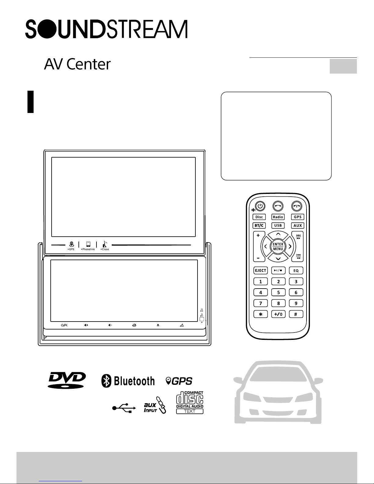
Creative 2-Screen Headunit
300W 4C H
2 DIN 6.95'' with
7'' TFT LCD Monitor
DVD/CD/MP3/MP4 Player
AM/FM Radio
Support Bluetooth
Support Navigation
Supportt USB PhoneLink
Owner’s Manual
VRN-DD7HB
EN

WARNING!
To promote safety, certain functions are disabled unless the parking brake is on.
The Unit is designed to detect parked status and must be connected to the power
supply side of the parking brake switch. Improper connection or use of his
connection may violate applicable law and may result in serious injury or damage.
To avoid the risk of damage and injury and the potential violation of applicable
laws, this unit is not for use with a video screen that is visible to the driver.
To a v o i d the risk of a c cident and t h e
potential violation of applicable laws, the
front Video image feature should never be
used while the vehicle is being driven. Also,
other video displays should not be in a
location where it is a visible distraction to
the driver. In some countries or states the
viewing of images on a display inside a
vehicle even by persons other than the
d r i v e r m a y b e i l l e g a l. W h e r e s uc h
regulations apply, they must be obeyed and
this unit's DVD features should not be used.
Please remember to wear your seat belt at
all times while operating your vehicle. If you
are ever in an accident, your injuries can be
considerably more severe if your seat belt is
not properly buckled.
The supplier waves any and all liability when
these warnings are not followed.
OPERATION PRECAUTIONS
Only connect to a 12V D C battery and
negative grounding.
Avoid placing the product in direct sunlight,
in a reas with high levels of dust, high
temperatures (over 40°C) or high humidity
(over 90%). In case of high temperatures,
cool down the car interior by means of
ventilation or air-conditioning.
Operate in well ventilated areas.
Do not turn on or off the product in short
intervals. When turning the unit off, wait for
at least 10 seconds prior to turning the unit
on again. Do not operate the player with
scratched, bended or b roken discs and
when a disc is not loaded properly, do not
force it into the player.
Do not watch video playback while driving
which will cause serious danger and risks of
traffic accident. It may violate the laws and
regulations.(There may be exceptional case,
i.e., using rear view camera and navigation
system)
Do not install the unit where the operation
for safety driving is restrained.
Do not disassembly the unit by yourself, if
need repairing, please take the unit to the
after service center.
Do not open and close the monitor manually,
it may damage the monitor tilt system.
Do not touch the LCD screen by hard objects,
it may damage or give scratch to the LCD
screen.
If the back of monitor touches dashboard or
air-con dition er i nlet etc afte r open the
monitor , then setup TILT level in monitor
TILT menu to prevent damage from repeat
touching.
Car parking under direct s unlight may
increase the temperature inside the car and
the unit may not be in proper operation,
please try it again after the temperature
returns to normal.
Do not replace the fuse on the power cable
wi t ho u t p ro f es s io n a l g u id a nc e , u si n g
improper fuse may cause damage to the unit
or even cause burn the unit.
Do not use irregular shaped Disk.
IR remote control operation may be hindered
by monitor when the monitor is opened, thus
please use the remote control at the similar
level of remote control receiver.
Do not install the unit where the cooling fan
is blocked.

Content
WARNING!....................................................................................................................................2
OPERATION PRECAUTIONS.............................................................................................................2
CONTENTS ..................................................................................................................................3
ACCESSORIES..............................................................................................................................4
INSTALLATION / UN-INSTALLATION .................................................................................................5
WIRING CONNECTIONS .................................................................................................................5
PANEL.........................................................................................................................................7
REMOTE CONTROL......................................................................................................................8
MAIN MENU................................................................................................................................9
•RADIO PLAYER..........................................................................................................................11
•USB INTERFEACE OPERATION.....................................................................................................12
•SETTING CONTROL....................................................................................................................13
Audio Setting........................................................................................................................13
General Setting.....................................................................................................................13
Radio Setting ........................................................................................................................14
Display Setting.....................................................................................................................14
DVD Ratio Setting.................................................................................................................14
Bluetooth Setting.................................................................................................................14
System Information..............................................................................................................14
•GPS SECTION...........................................................................................................................15
•MOBILE PHONE LINK SCETION....................................................................................................22
•BLUETOOTH SCETION................................................................................................................ 2 2
•AV-IN MODE.............................................................................................................................24
•R-CAMERA MODE......................................................................................................................24
•OTHER FUNCTIONS....................................................................................................................24
NOTES ON DISC..........................................................................................................................25
TROUBLESHOOTING....................................................................................................................26
TROUBLESHOOTING....................................................................................................................27
TECHNICAL SPECIFICATIONS........................................................................................................28
BLUETOOTH CONNECTION ATTENTION INSTRUCTIONS.....................................................................29
.
3
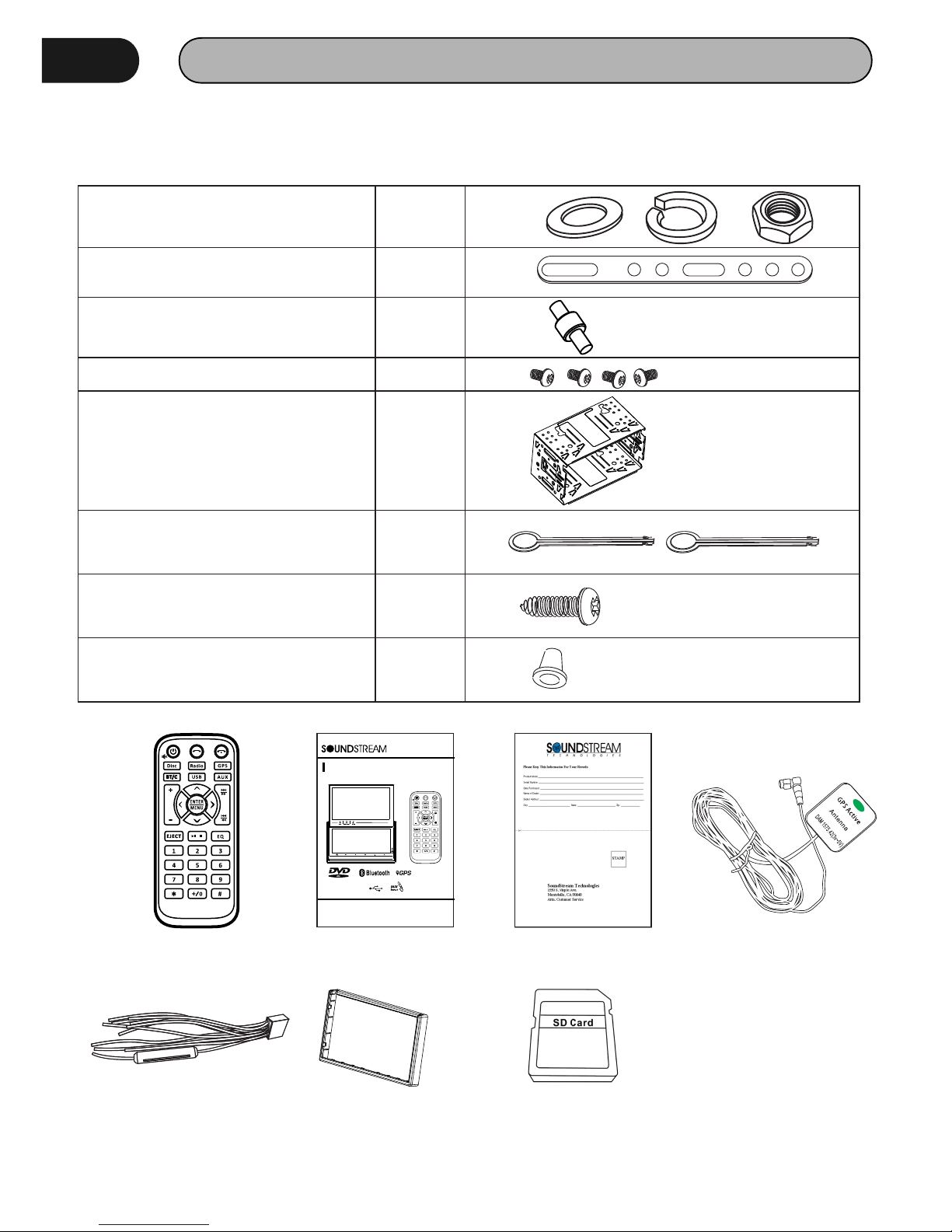
ACCESSORIES
Package contains the following accessories for installation and operation of the unit.
Remote Control
VRN- DD7HB
Engl ish
Owne r’s Man ual
300W 4 CH
2 DIN 6. 95'' &7 '' Doub le Moni tor
User Manual Warranty card GPS cable
Power cable Trim ring Micro SD card (Map)
Note:Product image may vary from the actual delivery.
(1) Washer, Spring Washer, M5 Nut 1 each
(2) Mounting Strap 1
(3) Bolt 1
(4) Screw 4
(5) Mounting Collar 1
(6) Release Key 2
(7) Screw 1
(8) Rubber Cushion 1
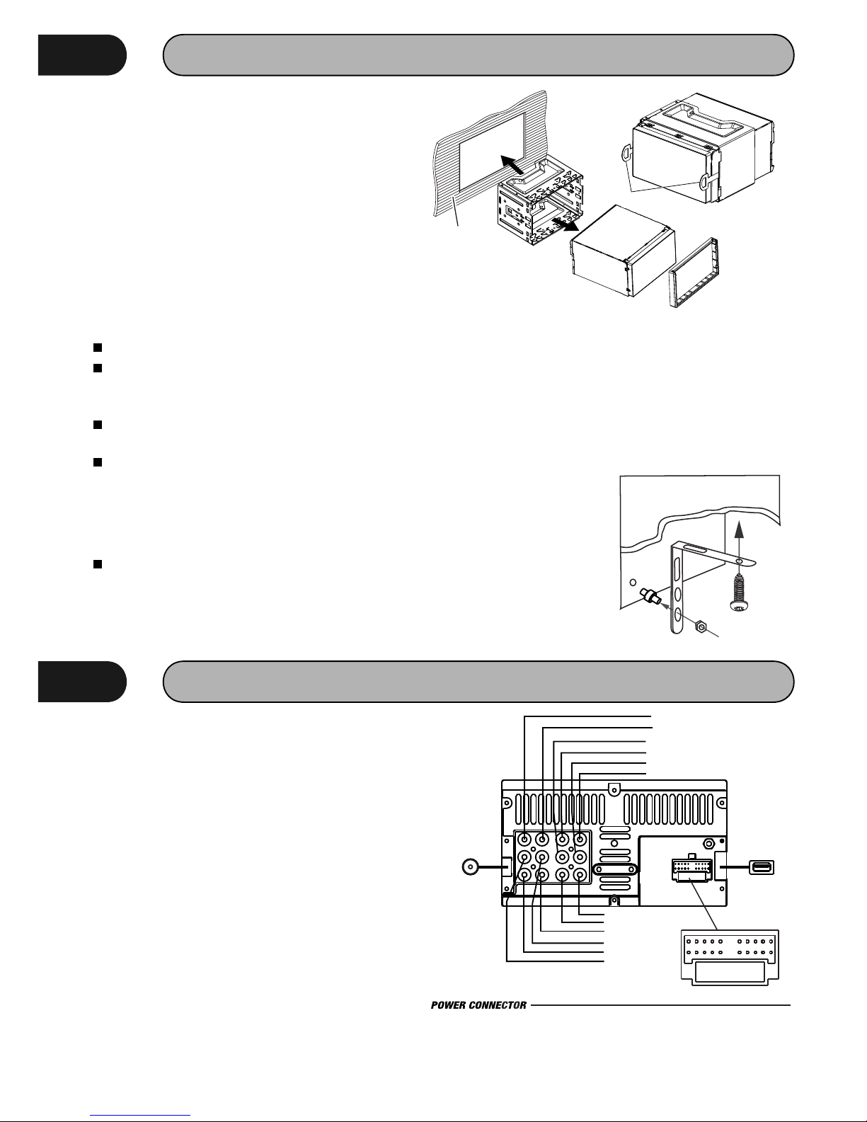
INSTALLATION / UN-INSTALLATION
Before starting installation of the unit, make sure
the wiring is connected properly.
Use only the parts provided with the unit to ensure
proper installation.
The u se o f u nauthorized p a r t s may c ause
malfunction.
Install the unit where it does not get in the driver's
way and will not injure the passenger in case
there is a sudden stop, like an emergency stop.
Note
Insert the unit into dash-board hole and fix it
If necessary, place the mount strap at the
rear of the unit and fix it with provided washer
as figure 2.
Push the unit into the Half Sleeve until you
hear a click sound
Place Trim Ring over the unit and installation
is completed as figure 3. (Some vehicle may
not need Trim Ring).
INSTALLATION (Figure 1)
Insert the supplied extraction keys into the
unit and pull the unit out with keeping the
extraction keys. (as Figure. 4)
UN-INSTALLATION
WIRING CONNECTIONS
Make sure you have good chassis ground. A good
ground connection will eliminate most electrical
noise problems. A good chassis ground requires a
tight connection to the vehicle's metal chassis.
The area around the ground connection should be
clean, bare metal without rust, paint, plastic,
dust, or dirt for a good electrical connection.
Caution: Do not interchange the connection of the
wiring!!!
For some car models you may need to modify
wiring of the supplied power cord. Contact your
authorized car dealer before installing this unit.
Using the power connector
Cut the connector; connect the colored leads of
the power cord to the car battery as shown in the
color code table below for speaker and power
cable connections.
V-OUT1 V-OUT2
CAM VIN
LIN RIN
FL FR
RL RR
Sub1 Sub2
V-O UT1
Yello w
Yello w
V-O UT2
Whi te
RL
Red
FR
Whi te
FL
Red
RR
Yello w
Whi te
Yello w
Red
Blu e
Blu e
Sub woofe r 2
Radio
Antenna
USB
Power Connector
1 2 3
4 5
6 7 8
9
10
11
12 13 14 15 16 1 7 18 19 20
1 FL+ (Whit e) 2 F L-(Wh ite/B lack) 3 RL+ (Gree n) 4 F R-(Gr een/B lack) 5 AC C 12V+( Red)
7 SWC 2 (Whit e/Blu e)
8 SWC 1 (Whit e)6 IR( Green ) 9 Cam era(B rown)
10 Pa rking B rake( Pink)
11 FR +(Gre y)
12 FR -(Gre y/Bla ck)
13 RR +(Pur ple)
14 RR -(Pur ple/B lack)
15 Gr ound- ( Black )
Fig ure .1
Dashboard
Fig ure .4
Fig ure .2
Fig ure .3
5
Sub woofe r 1
Rig ht inpu t
Vid eo inpu t
Lef t input
Cam era
A mounting strap id often included with new
stereos. For most installations, it is not necessary
part of the installation process. However, It can be
useful to help support the stereo in yr dash; it also
helps reduce vibration. One end of mounting strap
attaches (with a screw) to the rear of the stereo.
Mounting Strap
The other end attaches
to an exis ting bolt or
screw behind the dash.
Just bend the shape as
n e c e ss a r y t o e na b l e
mounting.
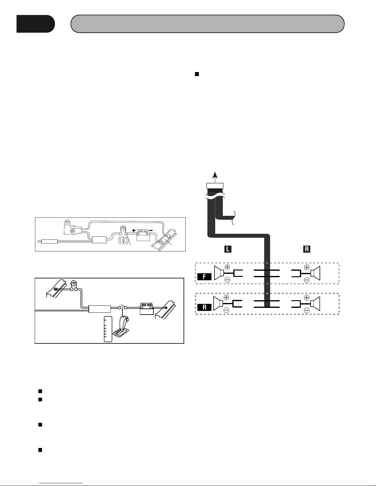
WIRING CONNECTIONS
NOTE: Never connect cable to the system while it
is connected to the battery power. Whenever the
unit is disconnected from the battery, the preset
memory will be erased and the unit will go back to
its factory defaults.
When the brown cable for steering wheel control
connected to the steering wheel, we can use the
steering wheel to control some unit.
ASWC Connections
To u s e a n e x t ernal u n iversal SWC m o d u l e,
connect only IR (Green) to the output of the
module.
Note: To watch video the parking wire should be
c o n n e ct e d t o b re a k s ig n al . 2 c a b l e s a re
connected to a Hands-Free device (not included).
Parking wire
Note: The parking wire is connected with brake
signal; for safety, the programs can be seen on
the monitor after braking the car..
Connecting the reversing line to taillight on the
car
After connecting, when you start up the reverse
gear, the unit will receive the picture from car rear
view camera.
Note:
Only use groundless loudspeakers.
Use only loudspeakers of minimum 40Watt,
using fewer watts may result in damaging
your loudspeakers at higher volumes.
Use 4~8 Ω (Ohm impedance) loudspeakers
only; using higher or lesser impedance may
damage the unit.
Do not use 3-cable loudspeakers and do not
connect the loudspeakers minus to the car
Connect the speakers according the following
diagram, incorrect connections will damage the
unit or your loudspeakers
(GND). The unit is using a BTL circuit and each
l o ud s p e a k er m u st b e c on n e c te d w i t h
insulated cables according the diagram.
Loudspeaker cables and/or optional external
power amplifiers must always be about 30cm
away from t h e a ntenna and/or antenna
extension parts.
Speaker Connection
White
Green
Grey
Purple
6
2A
Par king br ake lea d
Br own wi re
Br ake li ght
12 V
ba tter y
Ca r fram e
+
-
12V
Car f rame
Batter y
Rev erse dr iving l ight
Car f rame
Pin k wire
Rea r view vi deo cam era lea d
P
R
N
D
L
2
Gea rbox
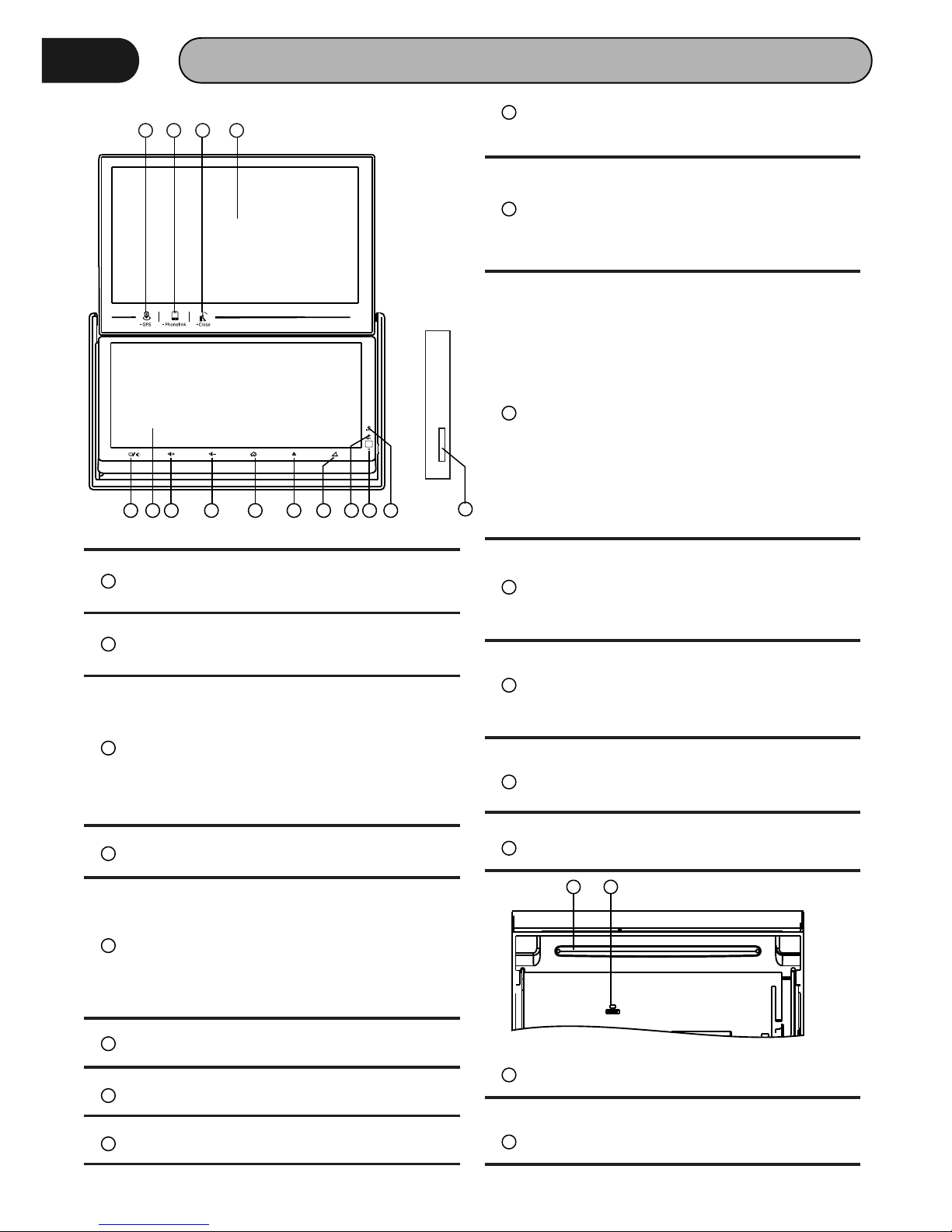
PANEL
1 2 3 4
5 6 7 8 9 10 11
12 13 14
15
1
GPS Button
Touch this Button, go to GPS mode
2
Phone Link Button
Touch this Button, go to Phone Link mode
3
Top Panel Close/ Adjustment Button
Condition: Top panel opened
Touch this button: Close top panel
Touch and hold this button for 3 seconds:
Adjust angle of top panel (Angle1 →
Angle2 → Angle3 → Angle4)
4
Top Panel
Top panel 7” display
5
Power Button/Mute
Touch this button to turn on or mute the
volume output, touch it again to resume
volume
Touch and hold this button for 3 seconds
to turn off the head unit
6
Bottom Panel
Bottom Panel 6.95” display
7
VolTouch this button to decrease volume
8
Vol+
Press this button to increase volume
9
Home Button
Touch this button to go back to main
menu of bottom panel
10
Eject Button
Touch this button to eject a disc. If the
disc is not removed for about 10 seconds
a f t e r e j e c t , t h e d i s c i s r e i n s e r t ed
automatically.
11
Panel Open/ Adjustment Button
Condition: top panel closed.
Touch this button: Open top panel
Touch and hold this button for 3 seconds:
Adjust angle of bottom panel (Angle1 →
Angle2 → Angle3 → Angle4 →Angle5 →
Angle6)
Condition: Top panel opened
Touch this button: No Function
Touch and hold this button for 3 seconds:
Adjust angle of bottom panel (Angle3 →
Angle4 → Angle5 → Angle6)
12
Reset Button
Press it with a thin, sharp object. The unit
wil l t hen be res et to fact ory defa ult
settings.
13
IR Sensor of Remote
IR r em o t e c o nt r o l s ig n a l r e ce i v in g
window. Max distance is 6-8 meters, 45
degree angle.
14
Mic
Build in Microphone for Bluetooth phone
calling.
15
Micro SD Card Slot
Micro SD card slot for GPS map.
16
Disc Slot
Insert & Eject disc
16 17
17
Reset Button
Reset the Unit.
7
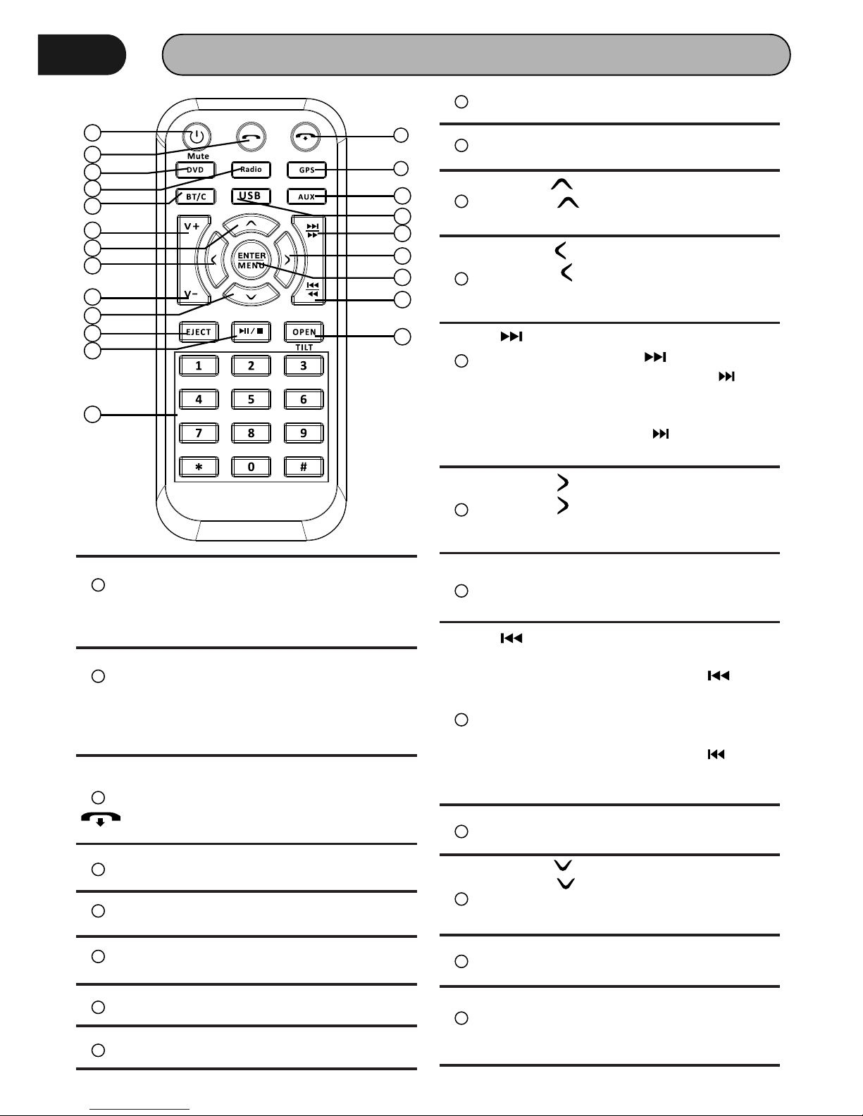
REMOTE CONTROL
1
POWER / MUTE
Press and hold to power it on or off. Short
press this button to mute the volume
output, press it again to resume volume.
2
DIAL/ ANSWER button (Only for Bluetooth)
Press to make a call after inputted a
phone number or answer an incoming
call.
3
REJE C T / HANG U P button (Onl y f or
Bluetooth)
Press to reject a coming call or hang up
while calling.
4
DVD button
Press it to DVD mode.
5
RADIO button
Press it to Radio mode.
6
GPS button
Press it to GPS mode.(Only for AVN model)
7
USB
Press it to USB mode.
9
BLUETOOTH button
Press it to Bluetooth mode.
10
VOL+ button
Press to increase volume level.
11
Cursor buttons
Use the buttons to select the menu
item, the title track or to show next frame.
12
13
/ button
In DVD mode, Press button to skip
to the next track, press and hold button
f o r t wo s e c o n ds t o a ct i va t e f as t
forward(FF) in a track.
In RADIO mode, press to start manual
searching button Frequency up.
15
MENU/ENTER button
Press it to confirm selection, Press and
hold show main menu..
16
/ button
Iin DVD mode, Press button to skip to the
previous track. Press and hold
button for two
seconds to activate fast reverse(REW) in
a track.
In RADIO mode, press and hold to start
manual searching button Frequency
down.
17
VOL- button
Press to decrease volume level.
1
2
3
4
5
7
6
8
9
10
11
12
13
14
15
16
17
18
19
20
21
22
8
AUX/AV IN button
Press it to AUX IN or AV IN mode.
Cursor buttons
Use the buttons to select the menu
item, The title tracks it or to show next
frame.
14
Cursor buttons
Use the buttons to select the menu
item, the title tracks it or to show next
frame.
18
Cursor buttons
Use the buttons to select the menu
item. The title tracks it or to show next
frame.
19
EJECT button
Press it to eject the disc.
20
PLAY/PAUSE/STOP button
In DVD mode, press it to stop playback,
press again to resume
8
REMOTE CONTROL
OPEN/TILT Button
Press this Button to open and close the
TFT monitor. WARNING: Do not obstruct
the m onito r w hile in the ope ning or
closing cycle, this may cause damage to
the monitor mechanism and i s N O T
covered under warranty.
Press and hold for 2 second to adjust the
Monitor tilt angle: TILT ANGLE 1 => TILT
ANGLE 2 => TILT ANGLE 3 => TILT ANGLE
4.
21
Digit 0-9 * # buttons
In radio mode, select 1-6 the desired
band; I n D V D m o d e , s e l e c t t r a c k . I n
Bluetooth mode,
0-9 * # enter the phone number or input
password.
22
REMOVE BATTERY
Note:
The d ista nce may vary a ccording to the
brightness of ambient light.
If the remote is not used for an extended
period of time, remove the battery to prevent
possible damage from battery leakage and
corrosion.
Do not place any objects between the remote
control unit and the sensor on the unit.
Do not drop the remote control onto the floor;
it will damage it beyond repair.
Do not use the remote control unit, while
simultaneously operating the remote control
unit o f a n y other e q u i p m e n t ; t h e y m a y
interfere resulting in improper operation.
Dispose empty batteries in accordance with
your local governmental regulations.
Do not short-circuit, disassemble, heat or
dispose of fire or flames the battery.
Keep the battery out of reach of children,
should the battery be swallowed, immediately
consult a doctor.
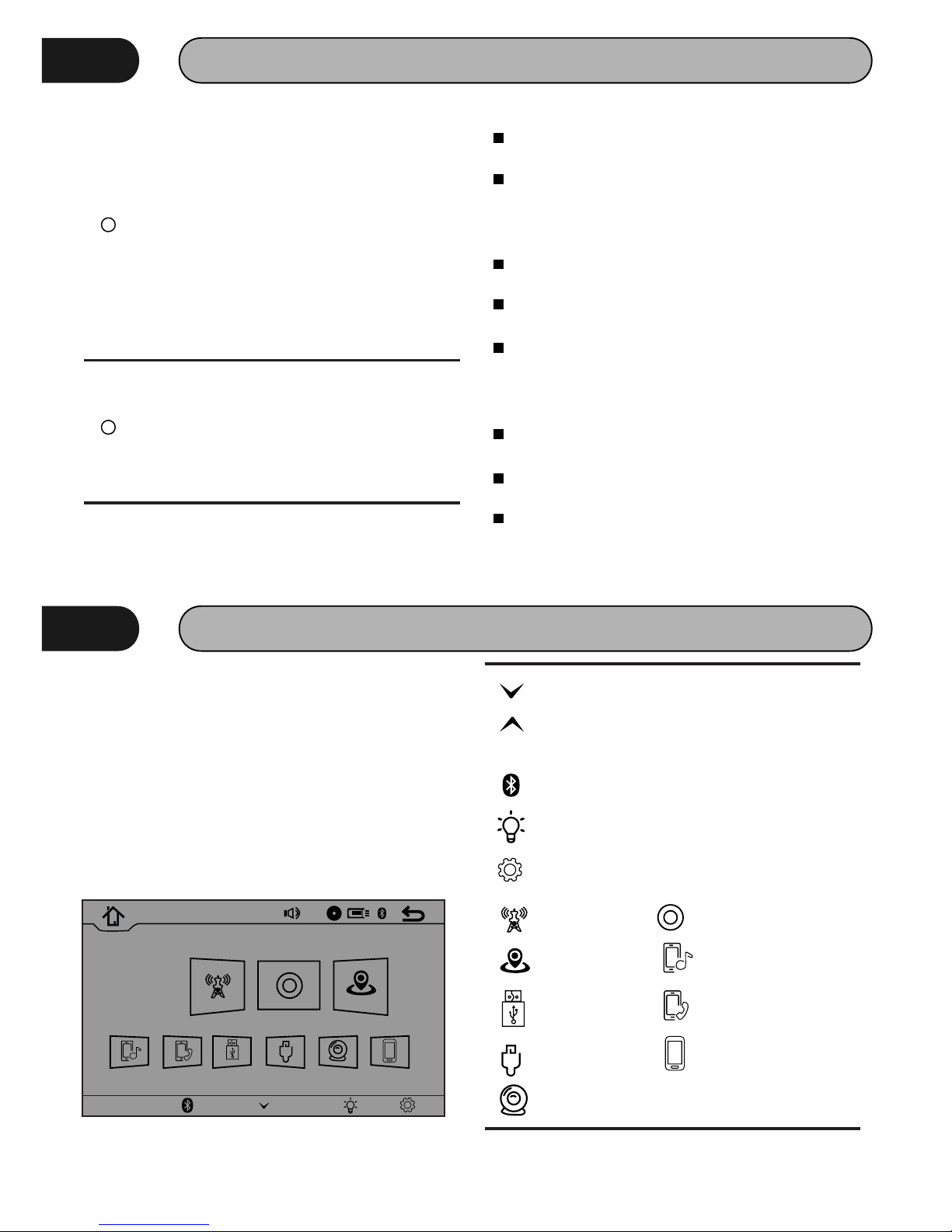
MAIN MENU
The best way to discover the program is to
explore each screen in detail, and to find out how
to move from one to another. Read this chapter for
a guided tour. Unit starts by displaying the Main
menu. This is the root of the screen hierarchy, and
you can simply access all features by tapping on
the touch screen buttons.
Touch the icons to enter a desired mode.
Console
HOM E
20
4:21 AM
01-01 -20 16
Monda y
Radio Disc GP S
BT- Music B T-Pho ne USB AV IN R-C amera P hone Li nk
Touch this key to view the hidden toolbar
Bottom Panel
Touch this key to hide the toolbar
Console
Touch this key to go back to main
Touch this key to enter Bluetooth setting
Touch t his key to adjust t he screen
brightness
Touch this key to enter setting menu
Radio mode Radio mode
GPS mode Bluetooth Music mode
Bluetooth Phone modeUSB mode
AV IN mode
Back View Camera mode
Phone Link mode
9
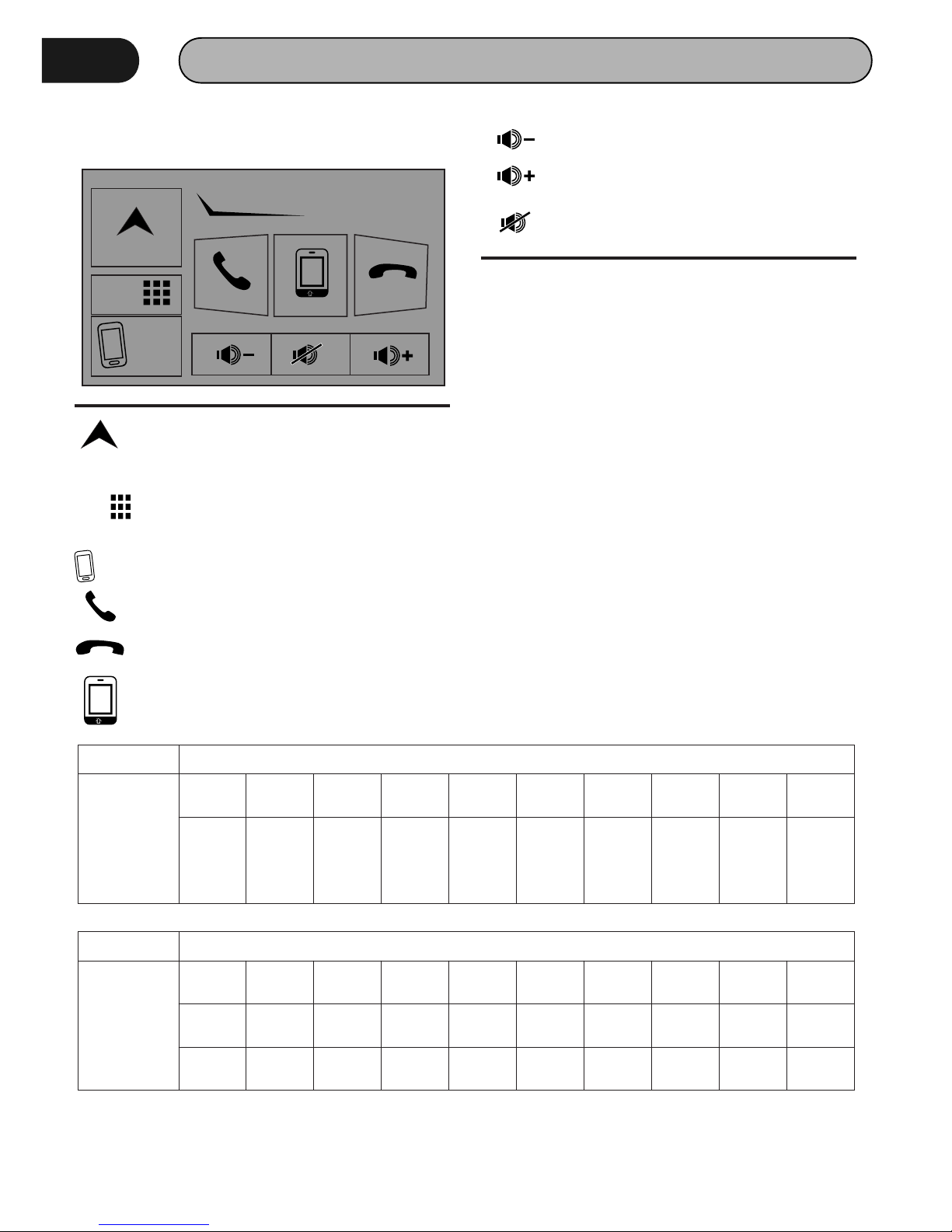
MAIN MENU
Bottom Panel
NAVI
Mode
Phone
Link
Console
GPS mode
Phone Link mode
Touch this key to answer a call
NAVI
Mode
Touch this key to select a desired mode
on bottom panel (Disc → USB → AV IN →
BT-Phone → Radio)
Phone
Link
Touch this key to end / reject the call
Touch this key to transfer a call from
Bluetooth mode to phone, and vice versa
Touch this key to decrease volume
Touch this key to decrease volume
Touch this key to switch the mute setting
to on or off
NOTE: The unit can be operated under the
following conditions
If top panel is open, operations of GPS mode and
Phone Link mode w ill s w i tch to t op p anel
automatically.
(1) GPS m o d e o n ly o p e r a t es on top p a n el.
Operations on bottom panel remain unchanged.
(2) Top panel shown either GPS mode or Phone
Link mode. Operations on bottom panel remain
unchanged.
(3) In USB mode, it is invalid to enter Phone Link
mode, and vice versa.
(4) Phone Link mode only operates on top panel.
O p e r a t i o n s o n b o t t o m p a n e l r e m a i n
unchanged.be swallowed, immediately consult a
doctor.
Bottom Panel
Mode Radio Disc
BT
Music
BT
Phone
USB AV IN
R-
Camera
GPS
Phone
Link
✔ ✔ ✔ ✔ ✔ ✔
✔
✔✔
Bottom Panel
Top Panel
Open
condition
Mode Radio Disc
BT
Music
BT
Phone
USB AV IN
R-
Camera
GPS
Phone
Link
GPS
Phone
Link
✔
✔
✔
✔
⍻ (1)
✘ (2)
✔ ✔ ✔
✔ ✔
✘ (3)
⍻ (4)
✘ (2)
✔
✔
✔
✔
Top Panel
close
condition
10
 Loading...