

Soundstream VR-732, VR-732B Owner's Manual
VR-732/
Monitor
Detachable
7"
VR-732B
Touch
DVD/CD/MP3/MP4
AM/FMRadio
With Bluetooth (only for VR-732B)
Screen
---------------------
EJ
tJ
.\
,.
n
_____________________
\.
SeUNDSTREAi
v1
,
Owner's Manual
Take the time
Familiarity
Performance
with
owner's
through
read
to
installation and operation procedures
new DVD-receiver.
your
from
this
manual.
will
help
obtain the best
you
To promote safety, certain functions are
designed to detect parked . status and must
parking brake switch.
and may result
potential violation
the driver.
• To avoid the risk of accident and the
image feature
displays should
countries or states the viewing of images
other than the driver may be illegal.
and this unit's DVD features
• Please
ever
properly buckled.
The
•
remember to wear your seat
accident, your injuries can
an
in
supplier
Improper
serious injury or damage. To avoid the risk of damage and injury and the
in
applicable laws,
of
should never
be
not
waves any and
connection or use of his connection may
be
location
a
in
should
all liability when these warnings are not
disabled unless the parking brake
this unit
potential violation
while
used
where it
Where such
be
not
belt
be
OPERATION PRECAUTIONS
on. The Unit
is
the power
connected
be
not for use with a video screen that is visible
is
vehicle
the
visible distraction to the driver.
a
is
display
a
on
regulations apply,
used.
times
all
at
considerably
to
of applicable laws,
being driven.
is
inside a
operating your
while
more severe if your seat
vehicle
supply side of the
violate applicable law
the front Video
Also,
they must be obeyed
vehicle. If
followed.
other video
even by persons
In
you are
belt
is
to
some
not
is
• Only
•
• Operate
•
•
•
•
•
•
• If
• Car parking under direct
•
•
• IR remote
•
connect to a 12Vdc battery and negative
direct sunlight,
Avoid
temperatures (over
down the car interior by means of
Do not turn
10 seconds prior to turning the unit
bended or broken discs and when a disc
player.
Do
traffic accident.
(There may be
Do
Do not
service center.
Do not open and close
Do not touch
screen.
then setup
may not
Do
fuse may cause damage
Do not use irregular
please
Do not
placing the product
40°C)
well ventilated
in
or off the product
on
not watch video playback while
It may
exceptional
install
not
disassembly
the back
not replace
use the remote control
install
the unit where the operation for safety driving
the
monitor touches dashboard or air-conditioner inlet
of
TILT level
proper operation,
in
be
the fuse
control operation may
the unit
violate
the unit by
LCD
in
shaped Disk.
where the
in
or high humidity (over
ventilation
areas.
in
laws
the
case, i.e., using rear view camera and navigation system)
yourself,
the monitor
screen by hard objects, it may damage or give scratch to the LCD
monitor
sunlight
on
to
TILT
may increase the temperature inside the car and the unit
please
the power
the unit or even cause burn the unit.
be
at the
cooling
grounding.
areas with high
in
case of high temperatures,
90o/o).
or air-conditioning.
short intervals.
again.
on
is
driving which will
and regulations.
if need repairing,
manually,
menu to prevent damage from repeat touching.
try it again after the temperature returns to
cable
hindered by monitor when the monitor
similar level
is
fan
When turning the unit off, wait for at
Do
loaded properly,
not
it may damage the monitor tilt system.
without
of remote
blocked.
In
not operate the
cause serious danger and risks of
restrained.
is
please
etc after open the monitor ,
professional
control
levels
player
do not force it into the
take the unit to the after
guidance, using improper
receiver.
of dust, high
with scratched,
is
cool
least
normal.
opened, thus
2
WARNING! ................................................................................................................. 2
OPERATION PRECAUTIONS .................................................................................... 2
ACCESSORIES .......................................................................................................... 4
UNIT INSTALLATION AND REMOVAL ...................................................................... 4
WIRING CONNECTIONS ........................................................................................... 7
PANEL ........................................................................................................................ 9
REMOTE CONTROL ................................................................................................ 1 0
REMOVE BATTERY ................................................................................................. 13
MAIN MENU ............................................................................................................. 13
+ RADIO PLAYER ................................................................................................... 14
+ DVD PLAYER ...................................................................................................... 15
+DISC/USB/SD/MMC INTERFACE OPERATION .................................................. 16
+AV-IN
+SETTING
MODE ......................................................................................................... 17
CONTROL ............................................................................................ 17
SOUND CONTROL .................................................................................................. 17
DISPLAY CONTROL ................................................................................................ 18
GENERAL CONTROL .............................................................................................. 18
RADIO CONTROL .................................................................................................... 18
DVD SET UP MENU ................................................................................................. 19
SYSTEM INFORMATION ......................................................................................... 20
CALIBRATION .......................................................................................................... 20
BLUETOOTH SECTION (ONLY FOR VR-732B) ......................................................
21
SMART CONTROL(ONL Y FOR VR-732) ................................................................. 23
OTHER FUNCTIONS ............................................................................................... 24
NOTES ON DISC ..................................................................................................... 25
TROUBLESHOOTING .............................................................................................. 26
TROUBLESHOOTING .............................................................................................. 27
TECHNICAL SPECIFICATIONS ............................................................................... 28
3
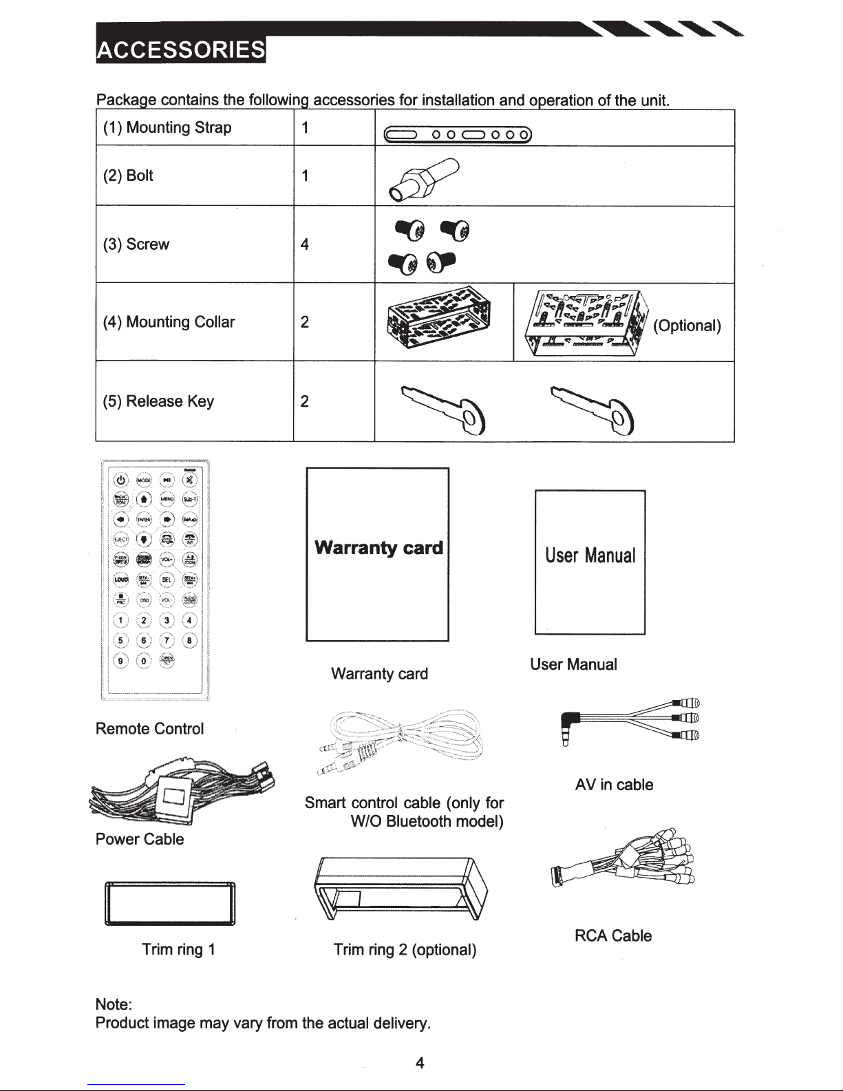
Packa e contains the followin
accessories for
installation
and o eration
of
the unit.
(1) Mounting
(2) Bolt
(3)
Screw
(4) Mounting Collar
(5)
Release
Strap
Key
1
1
4
2
2
p
o o
<::J
o o
o)
(Optional)
Remote Control
Power
Cable
II
Trim ring 1
Warranty card
Warranty card
Smart
control cable (only for
W/0
Bluetooth model)
Trim ring 2 (optional)
User
Manual
User Manual
r
AV
in cable
RCA Cable
Note:
Product image may vary from the actual delivery.
4
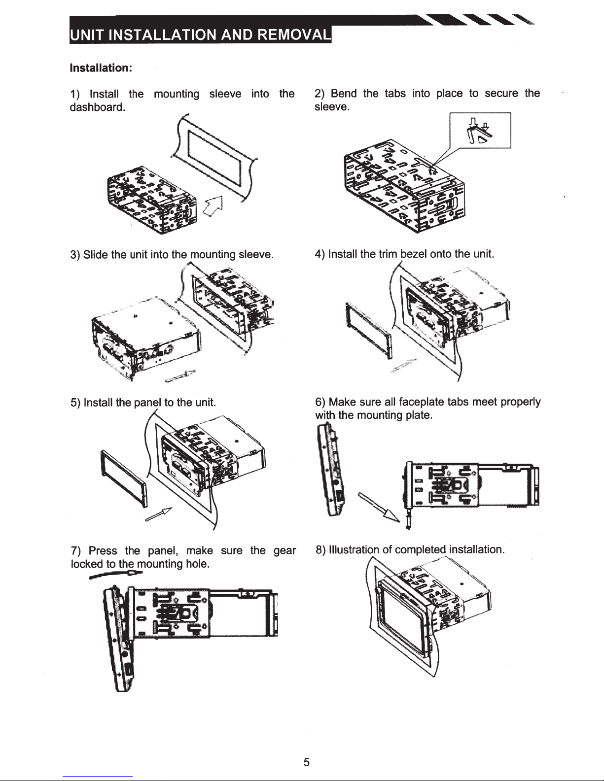
Installation:
Install
1)
dashboard.
the unit into the mounting
Slide
3)
the mounting
sleeve
into the
sleeve.
2) Bend the tabs into place to secure the
sleeve.
4)
Install
the trim
bezel
onto the unit.
5)
Install
the panel to the unit.
7) Press the
locked
to the mounting
CJI*
panel,
make sure the gear
hole.
6) Make sure
all
with the mounting
Illustration
8)
of completed installation.
faceplate tabs meet properly
plate.
5
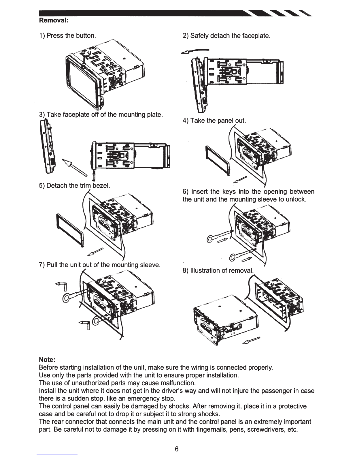
Removal:
1 ) Press the button.
3) Take faceplate off
of
5) Detach the trim bezel.
2) Safely detach the faceplate.
the mounting plate.
4) Take the panel out.
6) Insert the keys into the opening between
the unit and the mounting sleeve to unlock.
7) Pull the unit out
of
the mounting sleeve.
8) Illustration
of
removal.
Note:
of
Before starting installation
the unit, make sure the wiring is connected properly.
Use only the parts provided with the unit to ensure proper installation.
The use
Install the unit where it does not get
of
unauthorized parts may cause malfunction.
in
the driver's way and will not injure the passenger
in
case
there is a sudden stop, like an emergency stop.
The control panel can easily be damaged by shocks. After removing it, place it
in
a protective
case and be ·careful not to drop it or subject it to strong shocks.
The rear connector that connects the main unit and the control panel is an extremely important
part. Be careful not to damage it by pressing on it with fingernails, pens, screwdrivers, etc.
6

-
RADIO
ANT
0
0
0
0
0
L....--...:..:..:..==---
••••••••
7 '
s
1 3
••••••••
2 4 6 • 10
AMP
10
USE
POWER
Al+(GAEEN)
1 :
R.
5:
REVERSE
9 :
11:
:
13
:
15
CONNECTOR
-(WHilE/Bt.AaQ 8:
lAMP+[ORANGE
REMOTE
PARKING
BATTERY
11
13
"
16
14
12
AGC
Tl.IWON+(BWE,IWHITEJ
EIRAI(E.(PINK)
12V+(YEU.OW)
NOTE: Never connect cable
REPLACEMENT
RL-(GAEEN./Bl.ACK)
2:
(WHITE)
ct
FL
BLACK)
/
to the system
FUSE
ONLY
3 :AR+(PUAPLE)
-(GAEY/
FA
7 :
(ORANGE)
I.L
:
10
:POWER
12
GNO
:
14
IGNITION
:
18
it is connected to the battery power. Whenever
while
.__------~~Line~
"--
----...,;;,;~
-----=~~~~
~
Bl.ACK)
ANT+(Bl.UE)
(Bt.ACK)
12V+tREDJ
the unit is disconnected from the battery, the preset memory
back to its factory
When the brown
the steering
Note:
To watch video the parking wire
connected to a Hands-Free device (not
defaults.
cable
wheel to
for steering
control
some unit.
wheel control connected to the steering
should
be connected to break
included).
Parking wire
Note:
The parking wire is connected with brake
the monitor after braking the car.
signal; for safety, the programs can be seen
JJUne
....
Camera
Video
Out(FLJ
Out(FR)
Out(ALJ
Out
.__~=-a_plJne
L.........--.-..-a_plJne
--""~=------II..JI
-
~-II..JI
4 :M-{PURPLE/Bl.ACK)
FR+(GAEY)
8 :
be erased and the unit
will
wheel,
cables
signal.
2
will go
we can use
is
on
Parking
(Activated
by
parking
brake)
switch
Brake
Connecting the reversing
ne
reversing
To
li
Totaillight~
Battery
Car
To
line
To
taillight
to
Taillight
DVD
car
from
wire
Brake
Parking
~==============~?
ground
chassis
or
part
body
metal
on the car
line
7
player
your
of
(Pink/B
car
ack)
l
~~,4
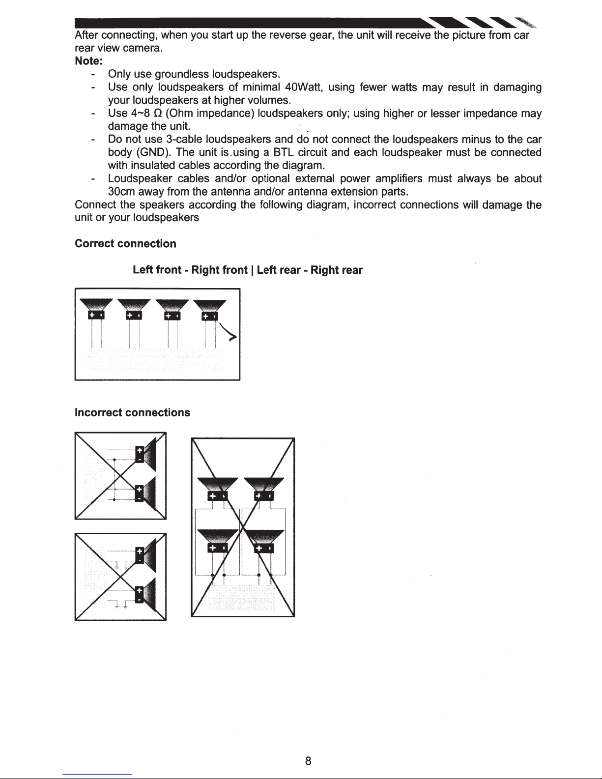
After connecting, when you start up the reverse gear, the unit will receive the picture from car
rear view camera.
Note:
Only use groundless loudspeakers.
Use only loudspeakers of minimal 40Watt, using fewer watts may result
your loudspeakers at higher volumes.
4-8
Use
damage the unit. .
Do not use 3-cable loudspeakers and do not connect the loudspeakers minus to the car
body (GND). The unit is.using a BTL circuit and each loudspeaker must be connected
with insulated cables according the diagram.
Loudspeaker cables and/or optional external power amplifiers must always be about
30cm away from the antenna and/or antenna extension parts.
Connect the speakers according the following diagram, incorrect connections will damage the
or
unit
Correct connection
your loudspeakers
0 (Ohm impedance) loudspeakers only; using higher or lesser impedance may
Left
front
- Right front I Left rear - Right rear
in
damaging
TTTT
i i I I I ! l
I i f I I ' '
I l I I I I l i
Incorrect connections
1").
i'
.
8
-
6
8
9
15
[
u~
.
~~~.~I
[
lf1
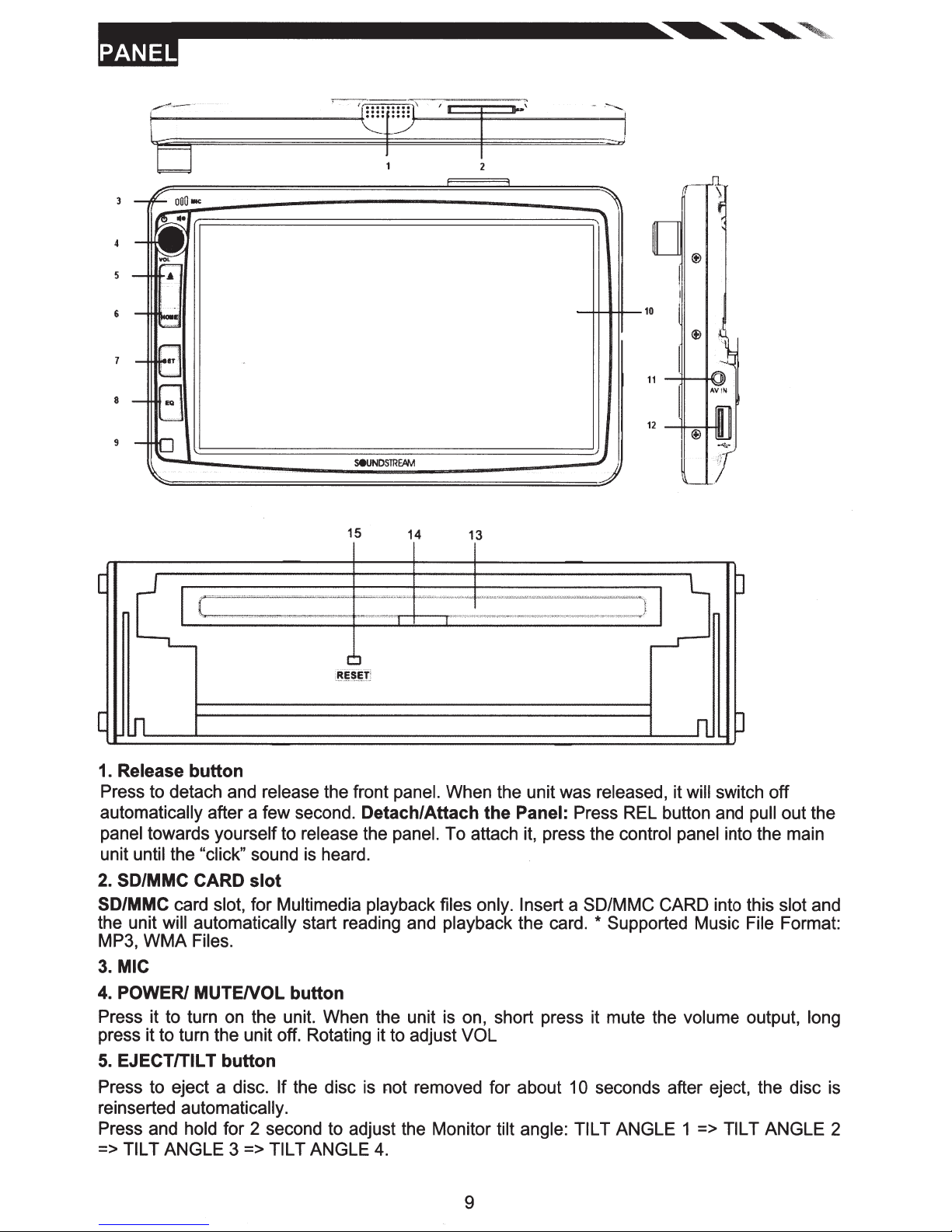
1. Release
Press to detach and release the front panel. When the unit was released, it will switch off
automatically after a few second.
panel towards yourself to release the panel. To attach it, press the control panel into the main
unit until the "click" sound is heard.
2. SD/MMC CARD
SD/MMC card slot, for Multimedia playback files only. Insert a SD/MMC CARD into this
the unit will automatically start reading and playback the card.
MP3,
3.
MIC
4. POWER/
Press it to turn on the unit. When the unit is on, short press it mute the volume output, long
press it to turn the unit off. Rotating it to adjust VOL
5.
EJECT/TILT
Press to eject a disc. If the disc is not removed for about 1 0 seconds after eject, the disc is
reinserted automatically.
Press and hold for 2 second to adjust the Monitor tilt angle: TILT ANGLE 1 => TILT ANGLE 2
=> TILT ANGLE 3 => TILT ANGLE
WMA
button
slot
Files.
MUTENOL
button
button
14
Detach/Attach
4.
13
0
lu
J
n
the
Panel: Press REL button and pull out the
* Supported Music File Format:
slot
and
9
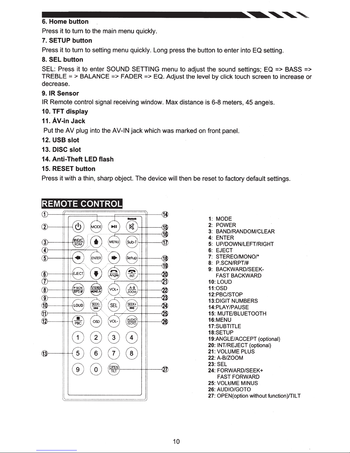
6.
Home
Press it to turn to the main menu
7.
SETUP
Press it to turn to setting menu quickly.
8.
SEL
SEL: Press it to enter SOUND SETTING
TREBLE
button
button
button
= > BALANCE
=>
quickly.
FADER
Long press the button to enter into EQ setting.
menu to adjust the sound settings; EQ
=> EQ. Adjust the level by
decrease.
9.
IR
Sensor
IR
Remote
10
..
TFT
11.
AV-in
Put the AV plug
12.
USB
13.
DISC
14.
Anti-
15. RESET
control signal
display
Jack
into the
slot
slot
Theft
LED
button
receiving window. Max distance is 6-8 meters, 45
AV-IN jack which was marked on front
flash
Press it with a thin, sharp object. The device will
click
touch screen to increase or
angels.
panel.
then be reset to factory default
=>
BASS
settings.
=>
REMOTE
0 0
CONTROL
000
'
o:;rr
r----+-+t---·U
1:
MODE
2:
POWER
3:
BAND/RANDOM/CLEAR
4:-
ENTER
5:
UP/DOWN/LEFT/RIGHT
6:
EJECT
7:
STEREO/MONO/*
8:
P.SCN/RPT/#
9:
BACKWARD/SEEK-
FAST BACKWARD
10:
LOUD
11:0SD
12: PBC/STOP
13:DIGIT
14:PLA Y/PAUSE
15:
16:MENU
17:SUBTITLE
18:SETUP
19:ANGLE/ACCEPT
20: !NT/REJECT
21:
22:
23:
24: FORWARD/SEEK+
25:
26:
27:
NUMBERS
MUTE/BLUETOOTH
(optional)
(optional)
VOLUME PLUS
A-B/ZOOM
SEL
FAST
FORWARD
VOL~ME
AUDIO/GOTO
OPEN( option without function)/TILT
MINUS
10
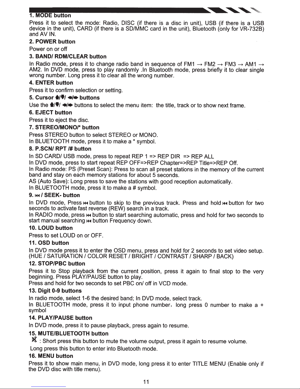
1. MODE
Press it to select
device
and AV
2. POWER
Power on
3.
BAND/
In
Radio mode, press it to change radio band
AM2.
wrong number. Long press it to
4. ENTER
Press it to confirm
5.
Cursor
Use the
6. EJECT
Press it to eject the disc.
7. STEREO/MONO/*
Press
In
BLUETOOTH
8.
P.SCN/ RPT
In
SO
In
DVD mode, press to start repeat REP OFF=>REP Chapter=>REP Title=>REP Off.
In
Radio mode:
band and stay on each memory stations for about 5 seconds.
AS
(Auto Save): Long press to save the stations with good reception automatically.
In
BLUETOOTH
9.
f-4~
In
DVD mode, Press
seconds to activate fast reverse (REW) search
In
RADIO
start
10.
LOUD
Press to set LOUD
11.
OSD
In
DVD mode press it to enter the OSD menu, press and hold for 2 seconds to set video setup.
(HUE
12.
STOP/PBC
Press it to
beginning. Press PLAY/PAUSE button to
Press and
13.
Digit
In
radio mode,
In
BLUETOOTH
symbol
14. PLAY/PAUSE
In
DVD mode, press it to pause
15. MUTE/BLUETOOTH
~
Long press this button to enter into
16. MENU
Press it to show main menu,
the DVD disc with
button
the mode: Radio,
in
the unit), CARD (if there
IN.
button
or
off
ROM/CLEAR
In
DVD mode, press to play randomly .In Bluetooth
button
t/•/
«•
t/•/
•I•
buttons to select
button
STEREO
CARD/
I
SEEK-
mode,
manual
button
I
SATURATION
0-9
: Short
button to
mode, press it to make a
/#button
USB
PS
mode, press it to make a
button
press~~~
searching
button
button
Stop playback
hold
for two
buttons
select
mode, press it to input phone number,
press this button to mute the
button
title menu).
button
selection or setting.
buttons
button
select STEREO or
mode, press to repeat REP 1 => REP
(Preset Scan): Press to scan
f-4~
button to skip to the previous track. Press and
button to start searching automatic, press and
H~
button Frequency down.
on or
OFF.
I
COLOR RESET
from the current position, press it again to
seconds to set PBC on/ off
1-6 the desired band;
button
button
in
DISC (if there is a disc
is
a
SD/MMC card
in
clear all the wrong number.
the menu item: the
MONO.
*
symbol.
#
symbol.
in
I
BRIGHT
play.
In
DVD mode, select
playback,
Bluetooth
DVD mode, long
press again to resume.
volume
mode.
in
unit),
in
the unit),
sequence
all
preset stations
a track.
I
CONTRAST
in
VCD mode.
output, press it again to resume
press it to enter
of
FM1
mode, press briefly it to
title, track or to show next frame.
DIR
=>
I
track.
long press
USB
(if there is a
Bluetooth (only
~
FM2
~
REP ALL
in
the memory
hold~~~
hold
for two seconds to
SHARP
TITLE
I
BACK)
final
stop to the very
0
number to make a
MENU (Enable only
for VR-732B)
FM3
~
AM1
clear single
of
the current
button for two
volume.
USB
~
+
if
11
 Loading...