

Soundstream VR-345, VR-345T, VR-345B, VR-345BT Owner's Manual

VR-345/VR-345T
VR-345B/VR-345BT
Flip-down/Detachable 3.4” Monitor
DVD/CD/MP3/MP4 Player
AM/FM Radio
Built-in TV tuner(only for VR-345T /VR-345BTmodel)
Support Bluetooth(only forVR-345B /VR-345BTmodel)
Owner’s Manual
Take the time to read through this owner’s manual.
Familiarity with installation and operation procedures will help you obtain the best
Performance from your new DVD-receiver.

2
Important Safeguards
Using the device at temperature below -10℃ may cause the breakage of the device.
BEFORE USING PLEASE HEAT UP THE PASSENGER COMPARTMENT TO THE
RECOMMENDED TEMPERATURE!
Read carefully through this manual to familiarize you with this high-quality sound
system.
Disconnect the vehicle's negative battery terminal while mounting and connecting the
unit.
When replacing the fuse, be sure to use one with an identical amperage rating. Using a
fuse with a higher amperage rating may cause serious damage to the unit.
DO NOT attempt to disassemble the unit. Laser beams from the optical pickup are
dangerous to the eyes.
Make sure that pins or other foreign objects do not get inside the unit; they may cause
malfunctions, or create safety hazards such as electrical shock or laser beam exposure.
If you have parked the car for a long time in hot or cold weather, wait until the
temperature in the car becomes normal before operating the unit.
DO NOT open covers and do not repair yourself. Consult the dealer or an experienced
technician for help.
Make sure you disconnect the power supply and aerial if you will not use the system for
a long period or during a thunderstorm.
Make sure you disconnect the power supply if the system appears to be working
incorrectly, (For example: making unusual sounds, smelling strange, emitting smokes
from inside or liquid having gotten inside it) Have a qualified technician check the
system.
The unit is designed for negative terminal of the battery, which is connected to the
vehicle metal. Please confirm it before installation.
Do not allow the speaker wires to be shorted together when the unit is switched on.
Otherwise it may overload or burn out the power amplifier.
Do not install the detachable panel before connecting the wire.
Don't remove the detachable panel when encoding.

3
Contenents
Important Safeguards ..............................................................................................................2
Contenents ...............................................................................................................................3
Accessories ..............................................................................................................................4
Installation/Un-Installation ........................................................................................................5
Wiring Connections ..................................................................................................................6
Front panel ...............................................................................................................................7
Inner panel ...............................................................................................................................7
Remote control .........................................................................................................................8
Remove battery ........................................................................................................................8
Main Menu ...............................................................................................................................9
General Operation ...................................................................................................................9
Radio operation ...................................................................................................................... 13
DVD/USB/SD/MMC Operation ............................................................................................... 14
TV Operations(Only for VR-345T /VR-345BTmodel) ............................................................. 17
Bluetooth Section(Only for VR-345B/VR-345BTmodel) ......................................................... 18
Anti-theft system .................................................................................................................... 20
Handling & Cleaning DISC ..................................................................................................... 20
Troubleshooting guide ........................................................................................................... 21
Specification ........................................................................................................................... 22
4
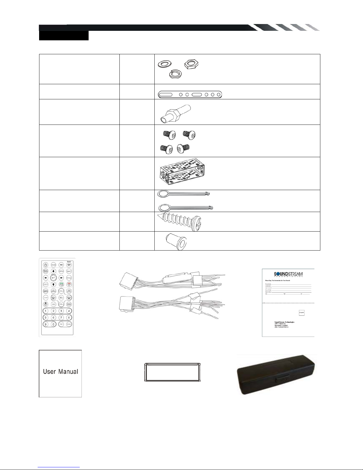
Accessories
Package contains th e fol l owing accessories for installation and operation of the unit.
(1) Washer, Spring
Washer, M5 Nut
1 each
(2) Mounting Strap 1
(3) Bolt 5*20 1
(4) Screw 5*6 4
(5) Mounting Collar 1
(6) Release Key 2
(7) Screw 5*20 1
(8) Rubber Cushion 1
ISO cable
Remote Control Warranty card
User Manual Trim ring
Note:
Product image may vary from the actual delivery.
1x front panel protec tio n case
5
Installation/Un-Installation
First complete the electrical connections, and then check them for correctness.
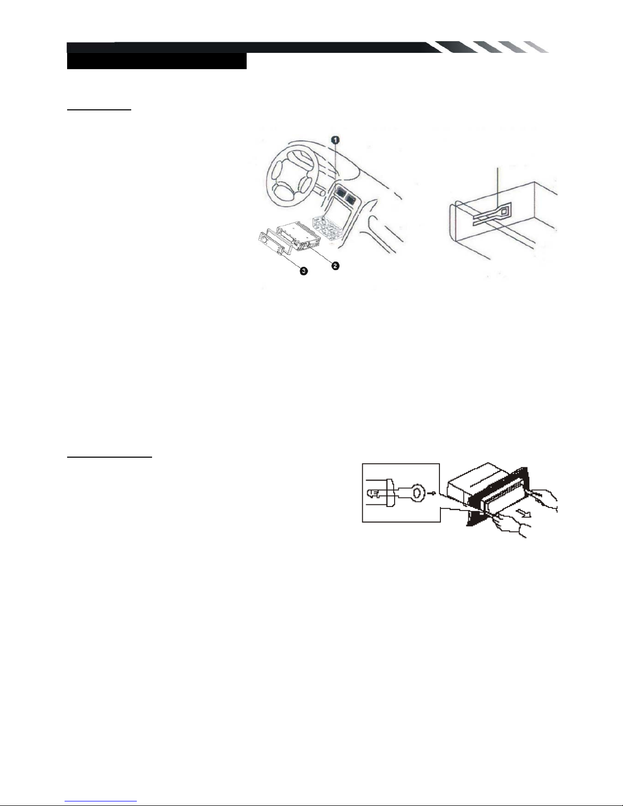
Installation
This unit can be installed in any
dashboard having an opening as
shown on the picture. The
dashboard should be 4.75 – 5.56
mm thick in order to be able to
support the unit.
1. Insert mounting collar into the
dashboard, and bend the
mounting tabs out with a
screwdriver.
Make sure that lock lever(※)is
flush with the mounting collar (not
projecting outward).
2. Secure the rear of the unit.
After fixing mounting bolt and power connector, fix the rear of the unit to the car body by rubber
cushion.
3. Insert trim plate.
When you prepare to insert trim plate, please check its direction. Once it was up side down, it
cannot be fixed.
Un-installation
Remove Trim Ring an d i nser t R elease Keys into left and
right side-end holes as shown in below picture and pull
the unit out of the dashboard.
Lock lever(※)

6
Wiring Connections
Make sure you have good chassis ground. A good ground connection will eliminate most
electrical noise problems. A good chassis ground requires a tight connection to the vehicle’s
metal chassis. The area around the ground connection should be clean, bare metal without rust,
paint, plastic, dust, or dirt for a good electrical connection.
Caution: Do not interchange
the connection of the wir ing!!!
For some car mo dels you may
need to modify wiring of the
supplied power cord. Contact
your authorized car dealer
before installing this unit.
1. If your car is equipped with
the ISO connector, then
connect the ISO connectors
as illustrated.
Using the ISO Connector
2. For connections without the
ISO connectors, check the
wiring in the vehicle carefully
before connecting, incorrect
connection may cause
serious damage to this unit.
3. Cut the connector; connect
the colored leads of the power
cord to the car battery as
shown in the color code table
below for speaker and power
cable connections.
Location Function
Connector A Connector B
1 Rear Right(+)---Purple
2 Camera (12V DC)--Pink Rear Right(-)---Purple/Black Stripe
3 Parking (GND)--Brown Front Right(+)---Grey
4 Battery 12V (+)--Yellow Front Right(-)---Grey/Black Stripe
5 Auto Antenna--Blue Front Left(+)---White
6 Front Left(-)---White/Black Stripe
7 ACC(+)--Red
Rear Left(+)---Green
8 Ground--Black Rear Left(-)---Green/Black Stripe
7
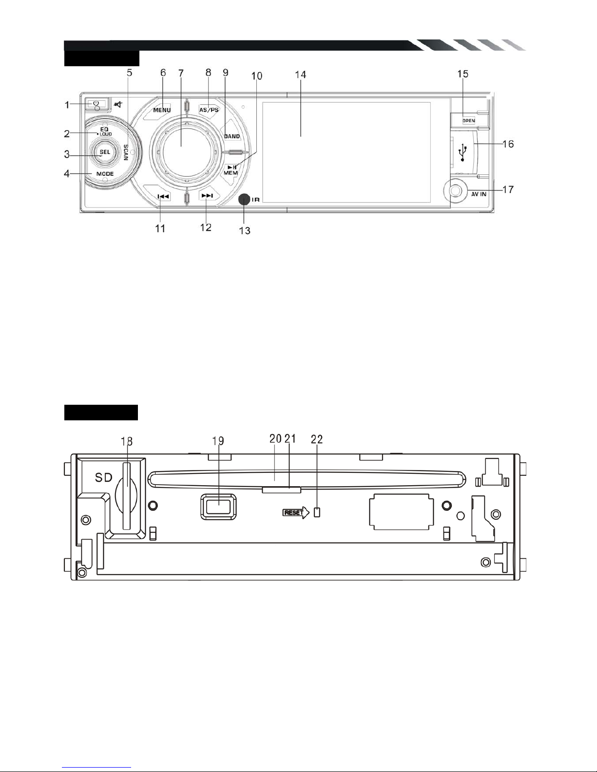
Front panel
1) Power /Mute button
2) EQ /LOUD button
3) SEL button
4) Mode button
5) SCAN button
6) MENU button
7) Volume/OK button
8) AS/PS button
9) BAND / Media select button
10) Play/Pause, Memory button
11) Previous / Reverse button
12) Next / Forward button
13) IR sensor
14) LCD Screen
15) OPEN button
16) USB slot
17) AV IN jack
Inner panel
18) SD/MMC card slot
19) Eject button
20) Disc loading slot
21) Anti-Theft LED flash
22) Reset button (hole)
NOTE:When turn off the power , the u nit w il l sw itch to st andby m ode unl ess c ut th e ACC p ow er.
The power light will continue lighting.
 Loading...