

Page 1

VGA 400.2
VGA 600.2
VGA 800.2
VGA 1600.2
VGA 320.4
VGA 500.4
VGA 800.5
Power Amplifiers
Owner´s Manual and Installation Guide
Page 2

CONGRATULATTONS!
You now own the Limited Edition VGA Amplifier, the product of an uncompromising design and
engineering philosophy. Your Soundstream VGA will outperform any other amplifier in the world.
To maximize the performance of your system, we recommend that you thoroughly acquaint yourself with
its capabilities and features.Please retain this manual and your sales receipt for future reference.
Soundstream amplifiers are the result of American innovation and the highest quality control standards.
When properly installed, they will provide you with many years of listening pleasure.Should your amplifier
ever need service or replacement due to theft, please record the following information which will help
protect your investment.
Serial #
Dealer's Name
Date of Purchase
Installation Shop
Installation Date
C A U T I O N !
Prolonged listening at extremely high levels may result in hearing loss.Even though your new
Soundstream Limited Edition VGA Amplifer sounds better than anything you've ever heard, exercise
caution to prevent hearing damage.
2
Page 3

TABLE OF CONTENTS
Features
Specification / Power ratings / Dimesions
Tools / parts for installation / Fuse requirements
Wiring / Power wire calculator
Wiring
Panel layout
Key to callouts
Trouble shooting / Protection circuit
2ch system design #1
2ch system design #2
4ch system design #1 / #2
4ch system design #3
4ch system design #4
4ch system design #5
5ch system design #6
3
p 4
p 5
p 6
p 7
p 8
p 9 ~ 12
p 13
p 14
p 15
p 16
p 17
p 18
p 19
p 20
p 21
Page 4

FEATURES
RUBI™ (Rapid-Use Branched Impulse) proprietary power supply topology
STACT™ (STabilized Apex Current Topologe) Reduces power supply stress by 50%
Trident™ amplifier protection topologe
Ultra-Low ESR Capacitance Bank ensures rapid power delivery for dynamic peaks
Hawkins Bass Control™ Proprietary bass equalization topology
IDI™ (I
ntelligent Distress Indicator) gives visual indication of amplifier protection status
Harmonic Bass Alignment™ Produces tighter, more accurate bass
Fully regulated MOSFET power supply
Triple Darlington Output Circuitry
BIP™ Bias I
nput Protection
Rail Stabilization Protection Circuitry
Bi-Linear selectable two-way crossovers for amplifier and line output
Continuously Variable High and Low Pass Crossovers
Balanced line Inputs for Highest level of Noise Rejection
Vortex Induction Fan Thermor Management
Platinum RCA Inputs and Outputs
Platinum 4-gauge Power Connectors
Tri-mode operation
STACT™(ST
abilized Apex Current Topology) Reduces power supply stress by 50%. In The STACT design,
inversion is done at the power amplifier drive stage. Since the fully symmetrical power amplifier
produces no evenharmonic distortion itself and all preamplifier circuitry is run completely inphase,no
even harmonic distortion phase reversal occurs and power is better distributed throughout the amplifier.
Advanced Trident™ Protection Topology Protects against potentially harmtul dmage in the following
situations:
1. Output Protection against short circuits or improper loads.
2. Voltage Inconsistencies protects against ground fault (speaker shorts to vehicle chassis) and an
under/over
voltage condition on the battery input.
3. Thermal Protection puts the amplifier into thermal rollback or shuts the amplifier down in extreme
thermal
conditions.
Hawkins Bass Control-Fully adjustable subwoofer equalization ciruit providing frequency and
bootst(“Q”)subwoofer for optimum subwoofer perfomance. Afrequency tracking subwoofer filter
protects subwoofer from potentially harmful low frequency information and maximizes output i a usable
range.
Tone Sweep Calibration Routine Automatically configures and optimizes the power supply to the
connected speaker load.
Continuously Variable Crossover Network 12 dB/octave low pass cross-overs variable from 50 Hz to 5k Hz
with a range selection switch
RCA Line Output Provides a full range signal output to drive other amplifiers.
Wire Connections Power and ground connections accept I\0 gauge cable, while the speaker
connections utilize dual 8 gauge connections.
ATT switch ‘ON’ for high voltage input(4V~12V) capability. This swich ‘ON’ must be used for peaker level
input on common ground head-units or for high voltage line drivers.
4
Page 5

SPECIFICATIONS
VGA400.2 100w X 2ch 200w X 2ch 400w X 1ch
VGA600.2 150w X 2ch 300w X 2ch 600w X 1ch
VGA800.2 200w X 2ch 400w X 2ch 800w X 1ch
VGA1600.2 400w X 2ch 800w X 1ch 1600w X 1ch
VGA320.4 80w X 4ch 160w X4ch 320w X 2ch
VGA500.4 125w X 4ch 250w X 4ch 500w X 2ch
VGA800.5
50w X 4ch 100w X 4ch 200w X 2ch
200 w X 1ch (sub) 400 w X 1ch (sub) 400 w X 1ch (sub)
MODEL 4ohm STEREO 2ohm STEREO 4ohm MONO
VGA400.2 2.6 inch 11.8 inch 11.2 inch
VGA600.2 2.6 inch 12.6 inch 11.2 inch
VGA800.2 2.6 inch 15.8 inch 11.2 inch
VGA1600.2 2.6 inch 18.9 inch 11.2 inch
VGA320.4 2.6 inch 13.8 inch 11.2 inch
VGA500.4 2.6 inch 15.8 inch 11.2 inch
VGA800.5 2.6 inch 18.9 inch 11.2 inch
DIMENSIONS Length Width Height
10 Hz - 50 kHz
< 0.02 %
115dB
0.15~12.0 Volts
10k Ohms
2 - 8 Ohms
4 - 8 Ohms
11 - 15 Volts
>500
>50 V/µS
Up to +18dB Boost @ 30Hz~100Hz
12dB/Octave
50Hz-5kHz
Power Bandwidth
Total Harmonic Distortion
S/N Ratio
Input Sensitivity
Input Impedance
Load Impedance (stereo)
Load Impedance (bridged)
Supply Voltage
Damping Factor
Slew Rate
Hawkins Bass
Crossovers
Crossover Frequency
DIMENSIONS
POWER RATINGS
5
Page 6
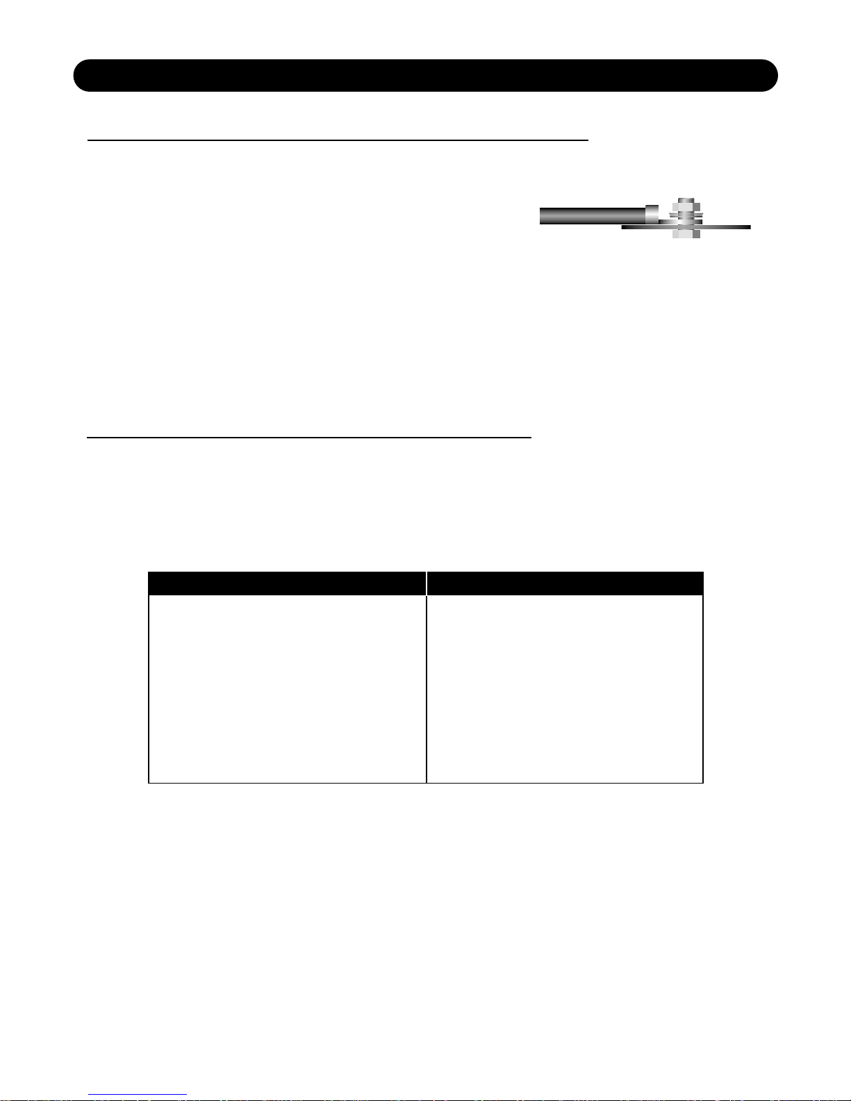
TOOLS / PARTS FOR INSTALLATION
NOTE: TOOLS ARE NOT SUPPLIED
Small flat blade screwdriver Phillips screwdriver (#2 or medium sized)
Wire cutters Wire strippers 7 - #6 round head screws, and 1 - #8 sheet
metal screw (or nut, bolt,flat washer, star washer) [see detail] 2 - Ring
connectors (large enough to accommodate your method of grounding) In-line fuse or
circuit breaker - see fuse chart below Power and ground wire - see Power Wire Calculator on page 7
Speaker wire - 12-16 gauge Grommets (sized to work with the power wire you plan to use in your
installation)
Tube of silicone sealant
FUSE REQUIREMENTS
VGA400.2
VGA600.2
VGA800.2
VGA1600.2
VGA320.4
VGA500.4
VGA800.5
Amplifier
60 Amp
80 Amp
140 Amp
90 Amp
100 Amp
60 Amp
40 Amp
Maximum Fuse Rating
You will need to install an in-line fuse or circuit breaker in the power wire within 18" of the battery. This fuse
or circuit breaker is to protect your vehicle from fire in case the power wire shorts to the vehicle body.
If you are only using one amplifier, use the fuse rating indicated in this chart. If you are using more than
one amplifier, add up the fuse ratings for all the amplifiers. This sum is the rating for your fuse or circuit
breaker. You may also want to add a power distribution block near your amplifiers to distribute large
gauge power cable to multiple amplifiers.
6
Page 7

WIRING
The following is a basic formula to be used as a guide to determine current draw. A 50% amplifier
efficiency rating is used as an average. Your new VGA amplifier is more efficient than most other amplifiers.
This formula is to be used as a guideline. Using wire of a larger gauge can only improve the current transfer
of your system. Do not use smaller gauge wire.
Total Amplifier RMS output x 2 = Total Input Wattage from car
Total Input Wattage
= Current Draw (in Amps)
Supply Voltage
Example: A VGA amplifier has two channels at 175w per channel RMS rating into 4 Ohms (175 x 2 = 350).
You would use the formula in the following way:
350W x 2 = 700W
700W
= 58.3 Amps Total current draw.
12V
If the same amplifier is driven into a 2 Ohm stereo or 4 Ohm mono load, double it's 4 Ohm RMS rating. All
VGA amplifiers will effectively double their power at this load.
(160W x 2) x 2 = 640W
640W
= 116.7 Amps Total current draw.
12V
If you are using more than one amplifier, add up the total current draw for all of them and choose the
appropriate gauge based on the grand total.
POWER WIRE CALCULATOR
NOTE: The ground wire must be the same gauge or larger as the power wire.
Total Current Draw Length Of Wire To Be Run
(in amps) Up to 4ft. 4 to 7ft. 7 to 10ft. 10 to 13ft. 13 to 16ft. 16 to 19ft. 19 to 22ft. 22 to 28ft.
25-50 10 10 8 8 6 6 4 4
50-65 8 8 6 4 4 4 4 2
65-85 6 6 4 4 2 2 2 0
85-105 6 6 4 2 2 2 2 0
105-125 4 4 4 2 2 0 0 0
125-150 2 2 2 2 0 0 0 00
150-200 0 0 0 0 00 00 00 000
200-250 00 00 00 000 000 000 000 0000
7
Page 8
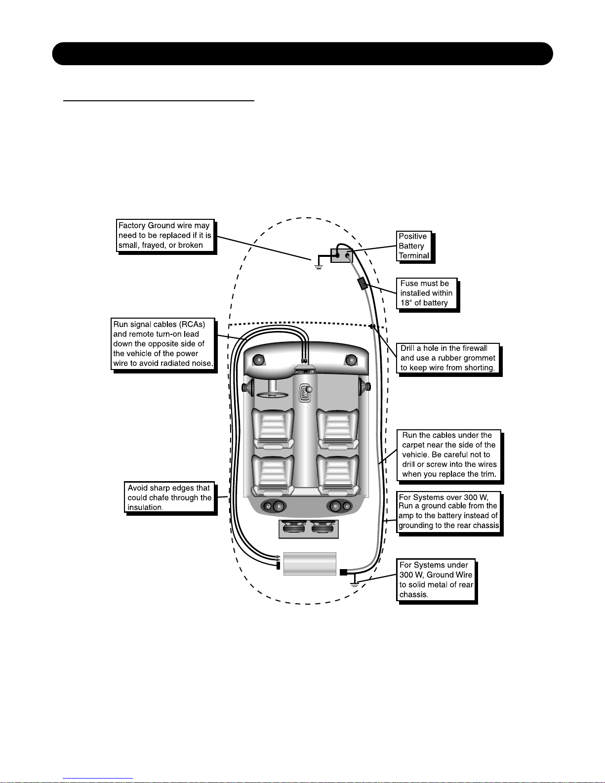
WIRING
Before beginning, disconnect the negative (-) terminal of the battery prior to working on the positive
(+) terminal to prevent a short to ground. This is important, unless you want to spend the rest of your life with
a nickname like "Sparky," or "Smokey." Reconnect the negative terminal only after all connections have
been made.
Warning! A Main Fuse must be installed within 18" of battery!
8
Page 9
9
TOP COVER
TOP VIEW FRONT VIEW
VGA 400.2
VGA 600.2
VGA 800.2
PANEL LAYOUT
Page 10
VGA 1600.2
TOP COVER
TOP VIEW FRONT VIEW
10
PANEL LAYOUT
Page 11
11
TOP COVER
TOP VIEW FRONT VIEW
VGA 320.4
VGA 500.4
PANEL LAYOUT
Page 12
12
TOP COVER
TOP VIEW FRONT VIEW
VGA 800.5
PANEL LAYOUT
Page 13
13
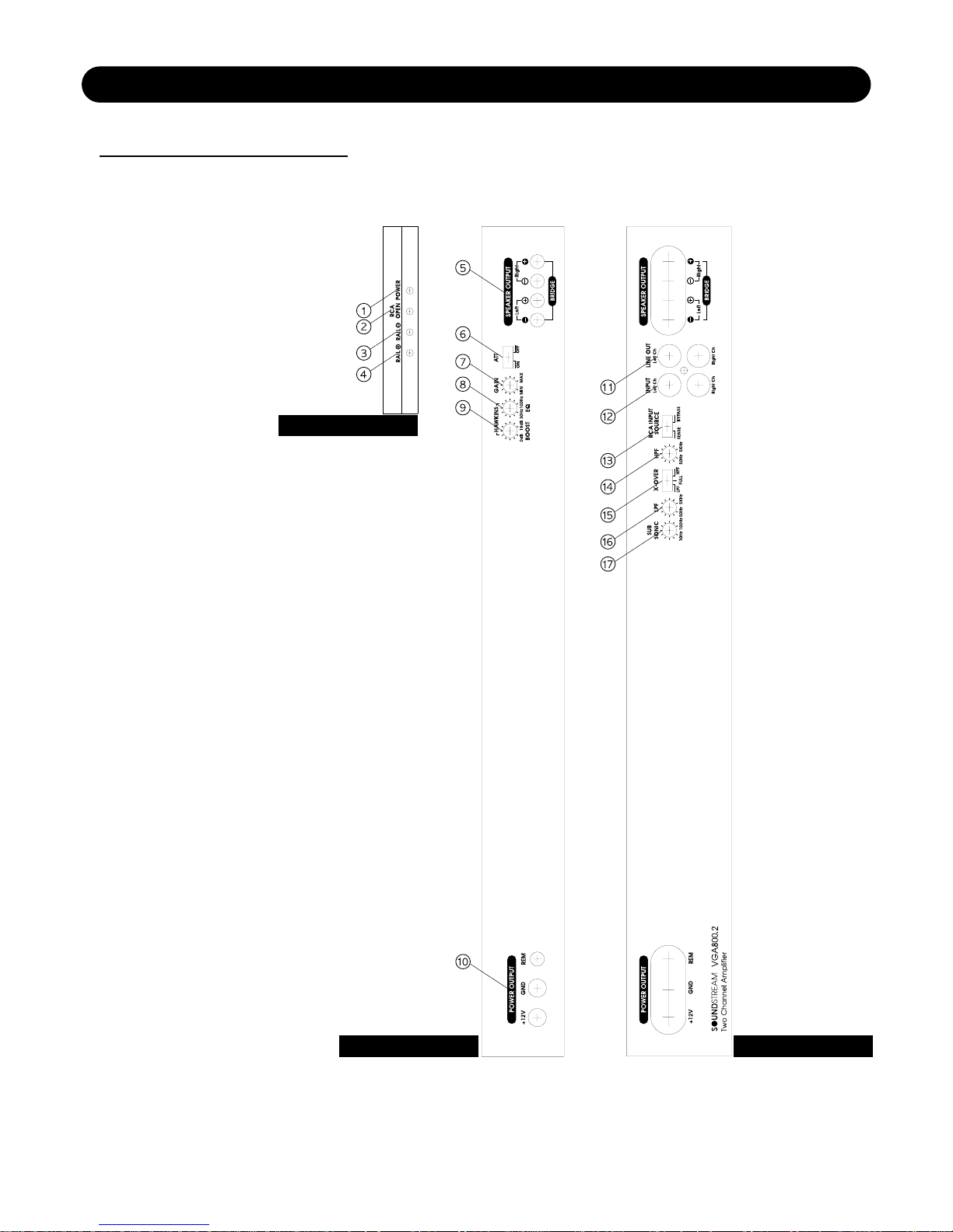
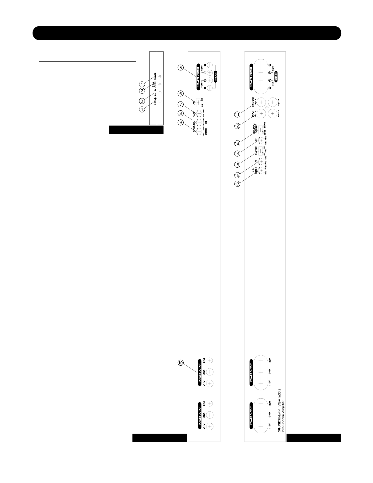
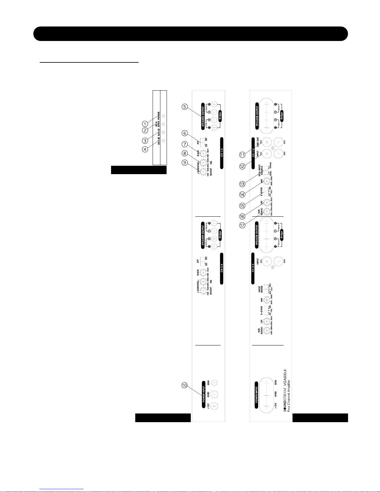
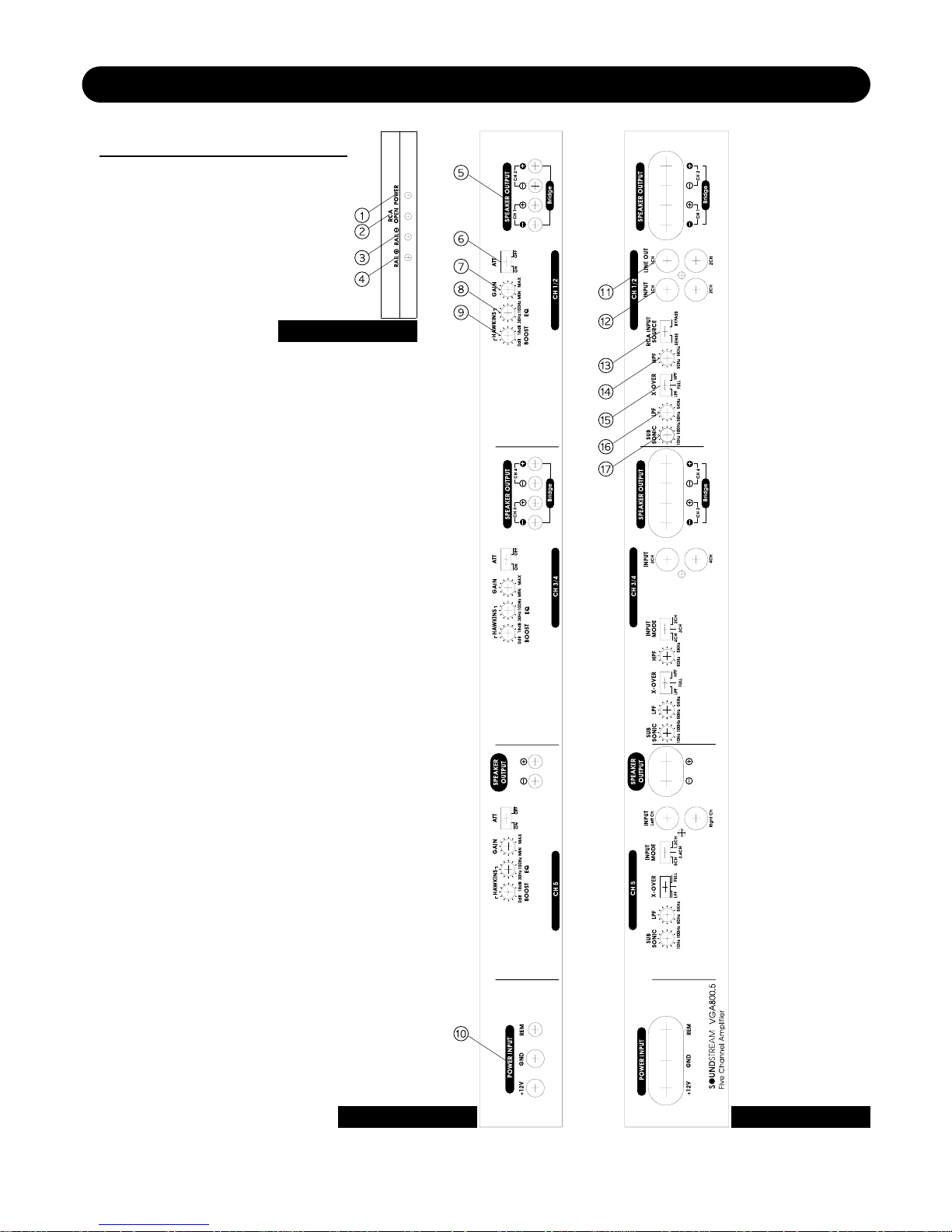
1. Power LED: Lights up when the amplifer is on.
2. RCA Open LED: Lights up when the RCA jack is opened.
3. RAIL LED: Lights up when valid voltage is decrease.
4. RAIL LED: Lights up when valid voltage is decrease.
5. Speaker Output Connections: The speaker connector in here.
6. Input Attention: Switch ‘ON’ for high voltage input(4V~12V) capability. This switch ‘ON’ must be used for
speaker level input on common ground headunits or gor high voltage line drivers.
7. Gain Control: Use this control to match the output level of the source-unit to the input of the amplifier.
8. Hawkins Bass Control Adjustmen: Frequency adjustment control for Hawkins Bass Control filter.
9. Hawkins Bass Control “Boost’’Adjustmen: Varies from 0 to + 18 dB of boost when the Hawkins Bass
Control circuit is engaged.
10. Power & Ground Connections: After connecting the power and ground r. Remote cables.
Remote: Remote turn- on input from the head unit.Accepts+12V GND: Main ground connection. Bolt to a
clean chassis point in the vehicle. +12V: Connected to a fuse or ciricuit breaker, then to the batter’s
positive terminal
11. RCA Line Iutputs: Left and right RCA outputs.
12. RCA Iutputs: Connect the RCA cables from source unit, or line driver to these RCA connectors.
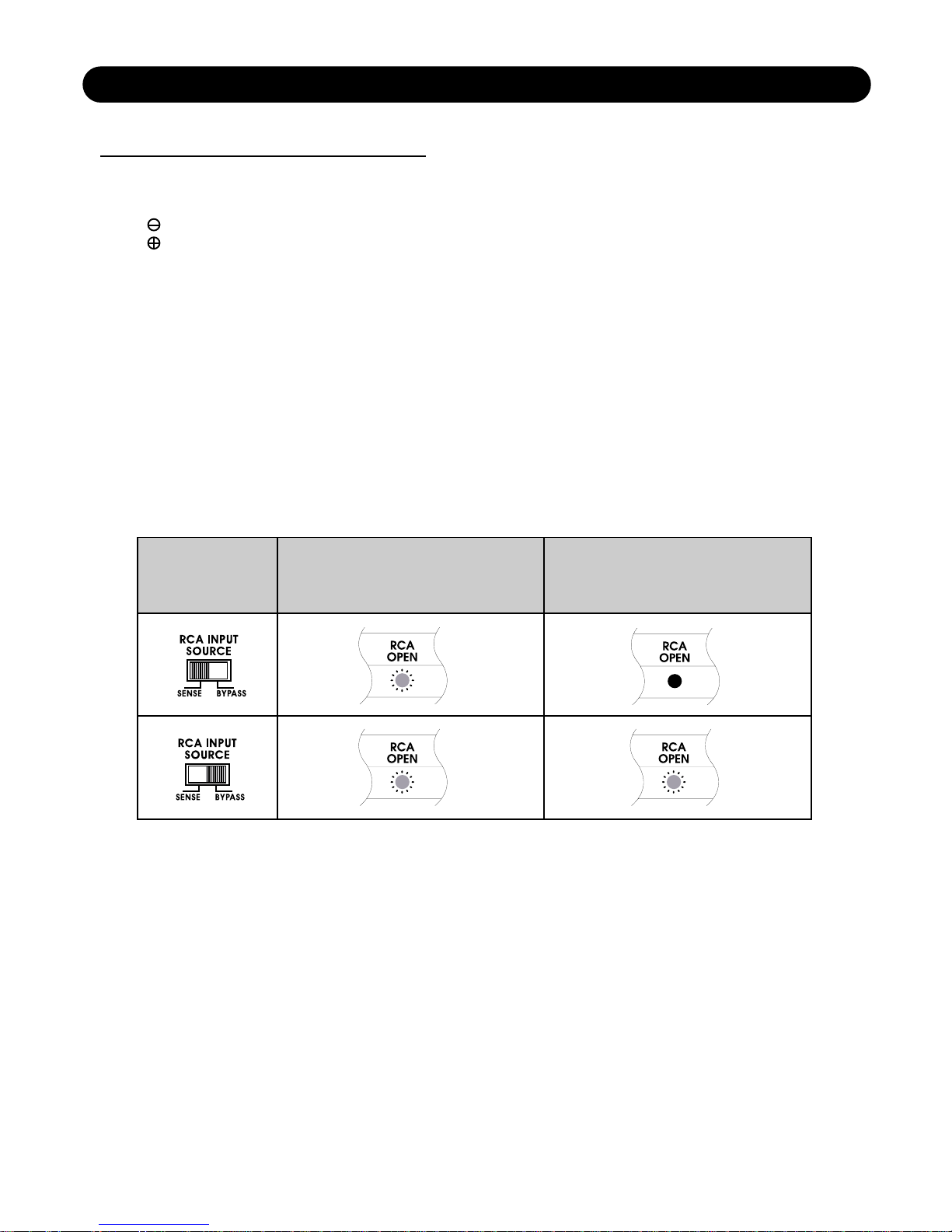
13. RCA In Put Source:
14. High pass Filter Control Adjustment: Frequency adjustment control for the High Pass Filter for satelite
CH1&2.
15. Crossover HP/LP/FULL Select Switch: Adjust this switch to select the HPF/LPF/FULL function for the
speaker outputs.
16. Low pass Filter Control Adjustment: : Frequency adjustment control for the Low Pass Filter for satelite
CH1&2 sum X-OVER.
17. Sub Sonic: Frequency adjustment control for the Sub sonic Filter for satelite CH1&2.
KRY TO CALLIUTS
In the case of RCA Jack from
Source unit is connected with
the input RCA Jack on amplifier.
In the case of RCA Jack from
Source unit is disconnected with
the input RCA Jack on amplifier.
Seletion
Page 14

NO SOUND Is the LED lit?
YES NO
Check Power and Remote turn-on
wire for voltage. Make sure Ground
wire is secure.
STILL NO SOUND
See your Authorized Sound Stream Dealer.
SOUND IN ONE CHANNEL ONLY
Reverse left and right speakers by unplugging the speaker connector, turning it over
and plugging it back in.
SOUND IS NOW IN
OPPOSITE CHANNEL SAME CHANNEL
Reverse RCA inputs Problem is in the speaker or
speaker wire of the silent channel
SOUND IS NOW IN
OPPOSITE CHANNEL SAME CHANNEL
Reverse RCAs at head unit Problem is in the Amplifier. See your
local Authorized
Dealer SOUND IS NOW IN
OPPOSITE CHANNEL SAME CHANNEL
Problem is in the head unit Problem is in the RCA cables
or before the amplifier
TROUBLE SHOOTING
PROTECTION CIRCUIT
Short Circuit Protection engaged: The amplifier will turn off and try to come back on immediately. The
amplifier will cycle like this indefinitely, with "blips" of sound each time. If this is the case, check your
speakers and wiring for low impedance and short circuits.
Thermal Protection engaged: The amplifier will turn off and several minutes later will come back on. In this
case, ensure that there is nothing blocking the normal convective airflow of the amplifier. No obstruction
should be within 2" of the amplifier on all sides.
NOTE: Low battery voltage will cause the amplifier to run warmer and possibly damage the amplifier.
14
Page 15
SYSTEM DESIGN #1
15
Page 16
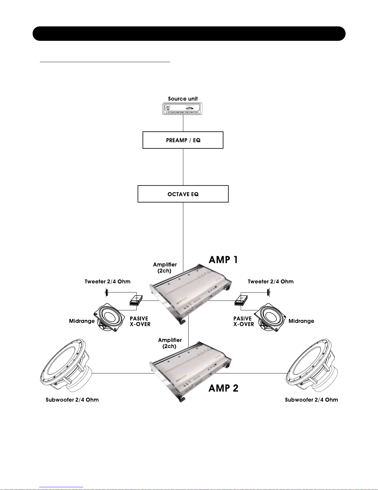
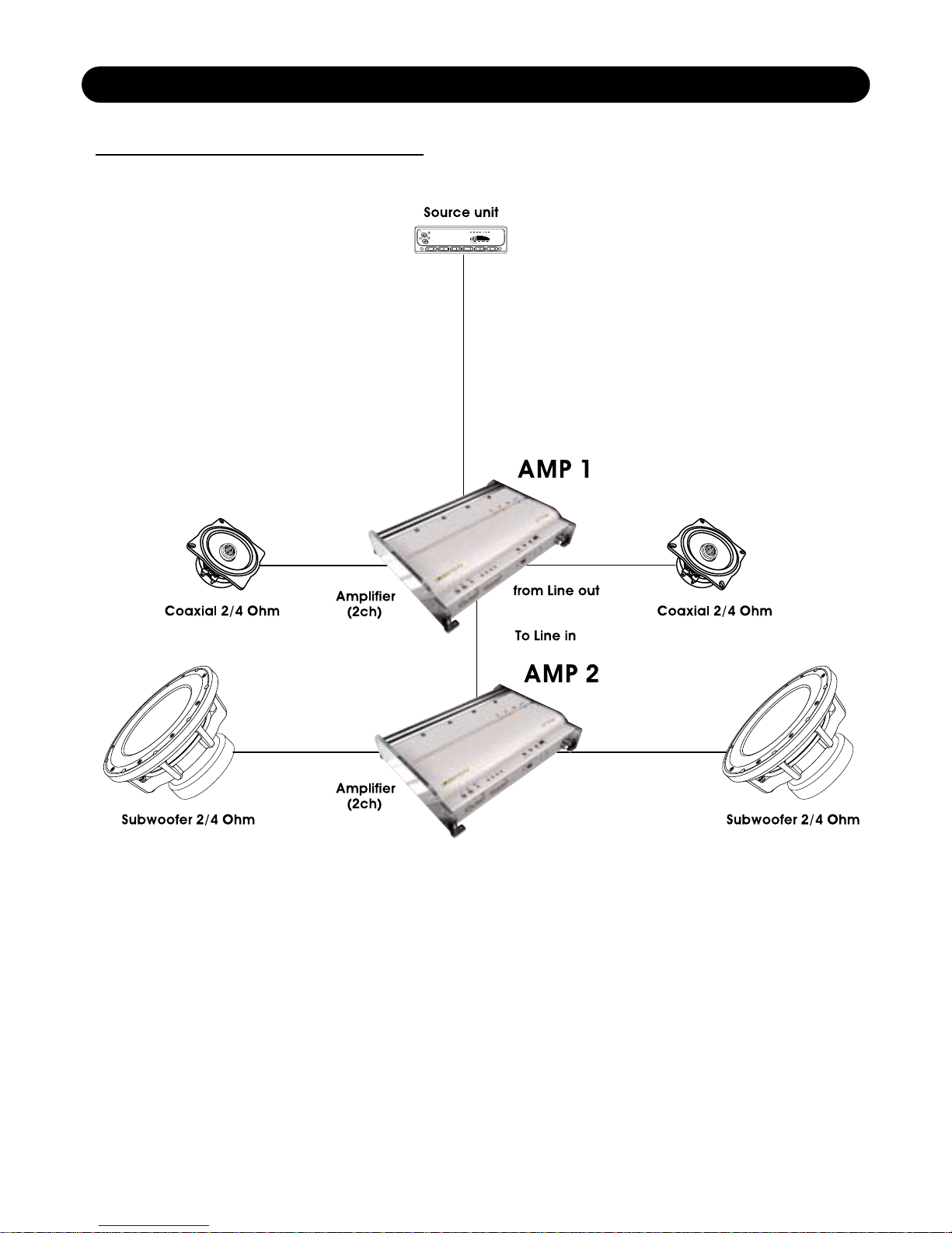
From Line Out
To Line In
16
SYSTEM DESIGN #2
Page 17
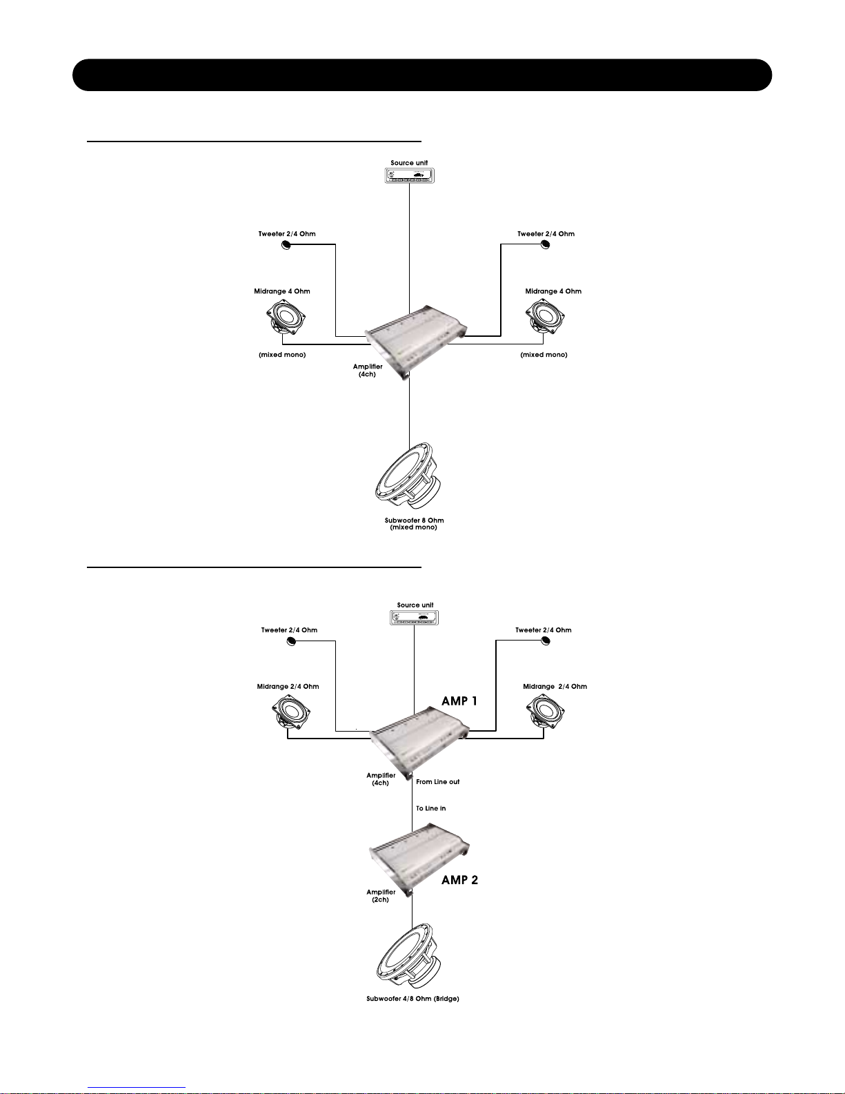
4CH SYSTEM DESIGN #1
4CH SYSTEM DESIGN #2
17
Page 18
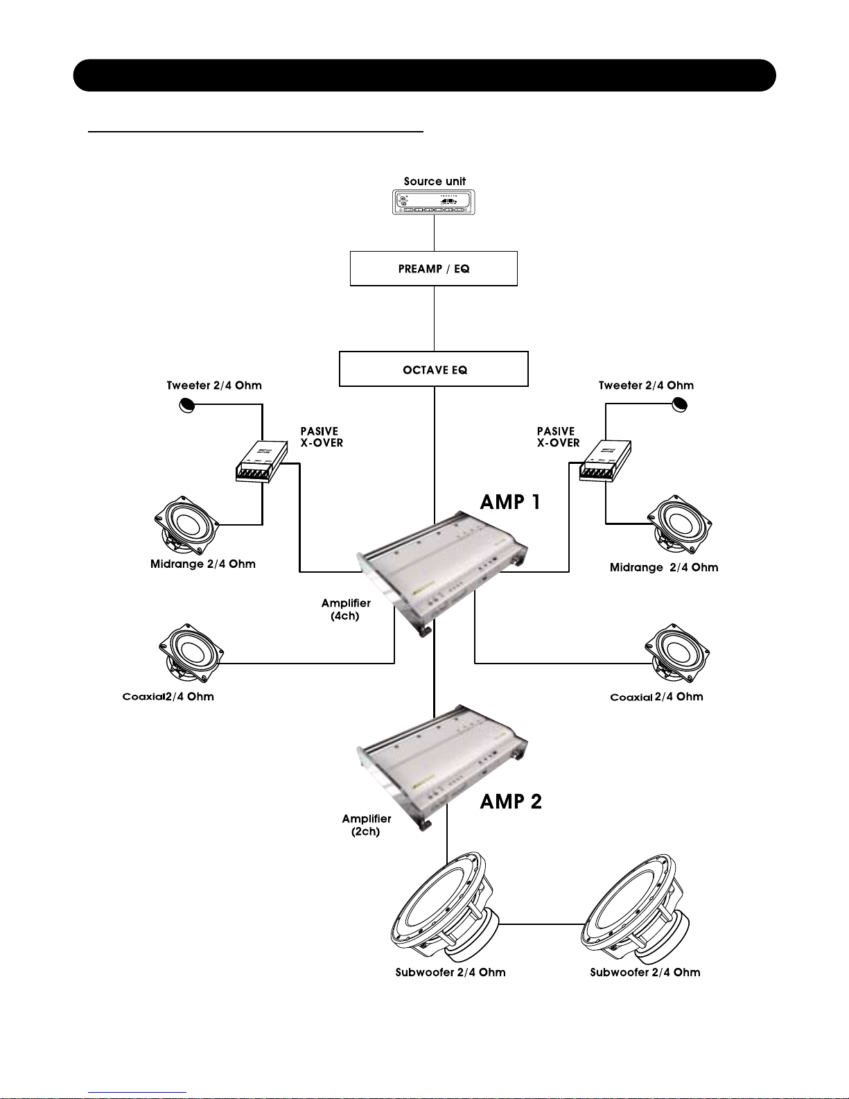
From Line Out
To Line In
18
4CH SYSTEM DESIGN #3
Page 19
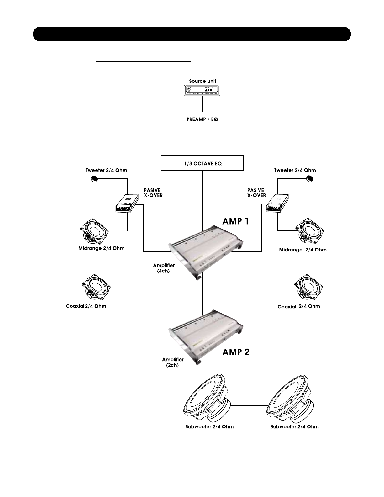
From Line Out
to Line In
19
4CH SYSTEM DESIGN #4
Page 20
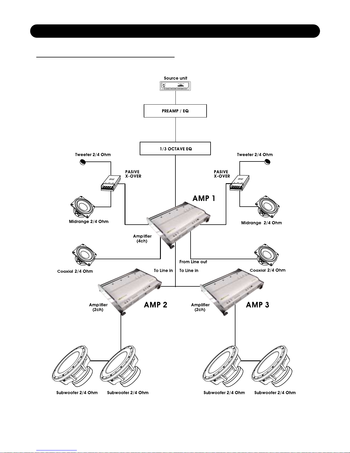
20
4CH SYSTEM DESIGN #5
Page 21
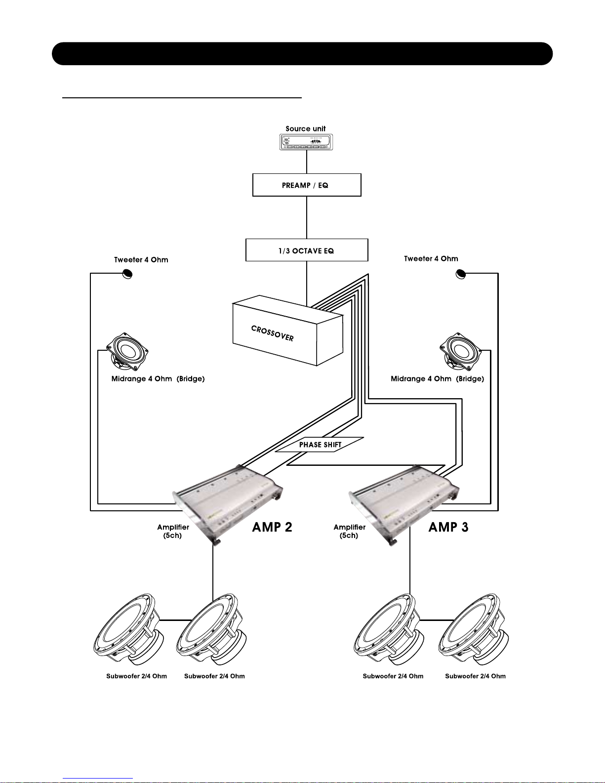
21
4CH SYSTEM DESIGN #6
Page 22

SOUNDSTREAM TECHNOLOGIES
1550 Maple Avenue., Montebello, CA90640 U.S.A
Phone 323-722-3333 fax. 323-722-1122
 Loading...