

Soundstream VDVD-210 Owner's Manual

UNDSTR
VDVD-210
Half-DIN
SD
Reader & USB
Take
the time to read through this owner's manual.
Familiarity with installation and operation procedures will help you obtain the best
Performance from your new DVD-receiver.
DVD/CD
Player with
2.0
Table
of
Contents
Table
Important
Accessories ....................................................................................................................... 3
lnstallation/Un-lnstallation .............................................................................................................. 4
Wiring
Panel
Remote
General
SD/MMC
Disc
MP3
Setup
Troubleshooting
Specification
of
Contents
Safeguards
Connections
Controls
Controls
Operations
Cards/
operations......................................................................................................................
overview .....................................................................................................................
MENU
....................................................................................................................... 1
................................................................................................................. 2
........................
......................................................................................................................... 6
........................................................................................................................ 7
.................................................................................................................... 9
USB
Operations
................................................................................................................................
Guide
.............................................................................................................................
..............................................................................................................
_.
............................................................................................. 5
............................................................................................. 9
11
14
15
19
19
Page-
1

Important
Safe
uards
Using
•
USING
TEMPERATURE!
Read
•
Disconnect
•
• Wlen
a
DO
•
the
Make
•
malfunctions,
If
•
car
DO
•
technician
the
PLEASE
carefully
replacing
higher
NOT
eyes.
sure
have
you
becomes
NOT
amperage
attempt
open
device
through
vehicle's
the
pins
that
or
parked
normal
covers
help.
for
temperature
at
HEAT
the
to
create
UP
this
fuse,
rating
disassemble
other
or
safety
car
the
before
and
THE
manual
negative
sure
be
cause
may
foreign
hazards
long
a
for
operating
not
do
may
terminal
with
one
damage
Laser
do
as
hot
in
unit.
yourself.
familiarize
to
battery
use
to
serious
unit.
the
objects
time
the
repair
-10°C
such
below
PASSENGER
breakage
cause
COMPARTMENT
yourself
while
an
beams
not
electrical
cold
or
Consult
the
mounting
identical
the
to
from
inside
get
shock
weather,
this
with
amperage
unit.
the
the
dealer
the
optical
or
wait
the
of
RECOMMENDED
THE
TO
high-quality
connecting
and
rating.
pickup
they
unit;
beam
laser
the
until
experienced
an
or
device.
sound
the
Using
dangerous
are
cause
may
exposure
temperature
BEFORE
system.
unit.
with
fuse
a
.
the
in
to
•
•
•
•
Make
period
Make
making
inside
The
Please
Do
may
sure
sure
unit
not
overload
you
during
or
you
unusual
Have
it)
designed
is
confirm
allow
disconnect
thunderstorm.
a
disconnect
sounds,
qualified
a
for
before
it
speaker
the
burn
or
the
the
smelling
technician
negative
installation.
wires
power
the
out
power
power
strange,
terminal
be
to
emitting
check
of
and
if
the
supply
supply
shorted
amplifier.
aerial
system
the
smokes
system.
the
battery,
together
you
if
appears
which
when
will
from
is
the
use
not
working
be
to
inside
connected
unit
or
switched
is
the
liquid
to
system
incorrectly,
having
vehicle.
the
Otherwise
on.
for
gotten
long
a
metal.
C
e.
g,
it
Page
-2
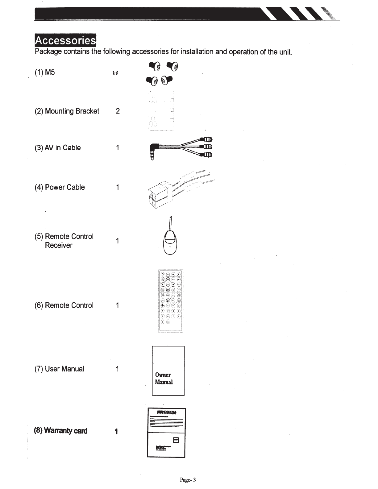
ccessor1es
Package
(1)
M5
(2)
Mounting
(3)
AV
(
4)
Power
contains
in
Cable
Cable
Bracket
the
following
accessories
2
1
1
r
for
installation
and
operation
of
the
unit.
(5)
Remote
Receiver
(6)
Remote
(7)
User
Control
Control
Manual
1
1
1
Owner
Manual
(8)
Warranty
card
1
Page-
3
----
---
--
-
--
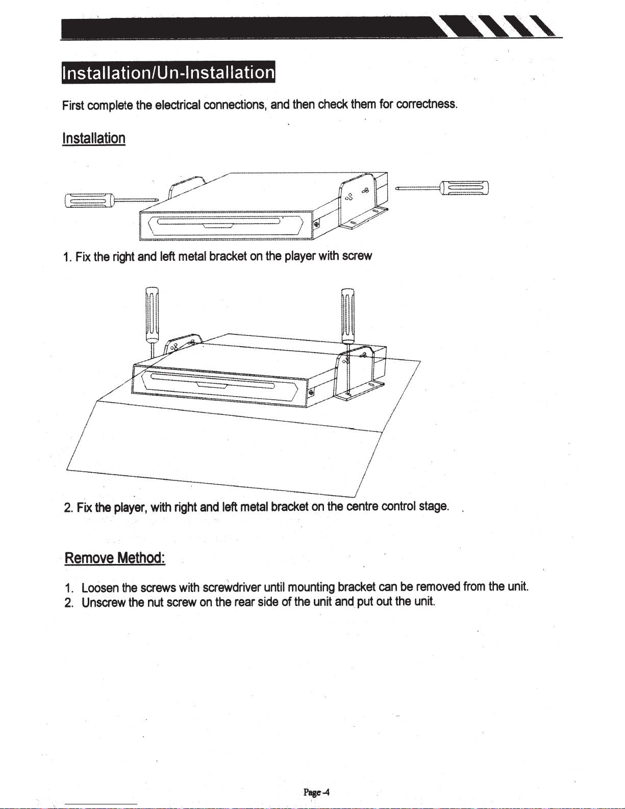
I nstallati
complete
First
Installation
right
the
Fix
1.
--
---
on/U n
electrical
the
left
and
·
---
--
---
nsta
-I
connections,
bracket
metal
--
----
llati
on
on
------
-
and
the
----
then
player
--
---
check
with
-----
them
screw
----
- -
--
---
-
correctness.
for
--
---
the
Fix
2.
Remove
-
Loosen
1.
Unscrew
2.
with
player,
·
.
Method:
screws
the
nut
the
right
with
screw
metal
left
and
screWdriver
rear
the
on
bracket
until
side
_/
on
mounting
unit
the
of
centre
the
bracket
and
put
control
be
can
the
out
stage.
removed
unit.
from
the
unit.
Page-4
irin Connections
Make
sure
you
have
good
noise
The
or
dirt
problems.
area
around
for
a
good
A
good
the
ground
electrical
chassis
chassis
connection
connection.
ground.
ground
A
good
requires
should
be
ground
a
tight
clean,
connection
connection
bare
metal
will
to
the
without
eliminate
vehicle's
rust,
paint,
most
metal
plastic,
electrical
chassis.
dust,
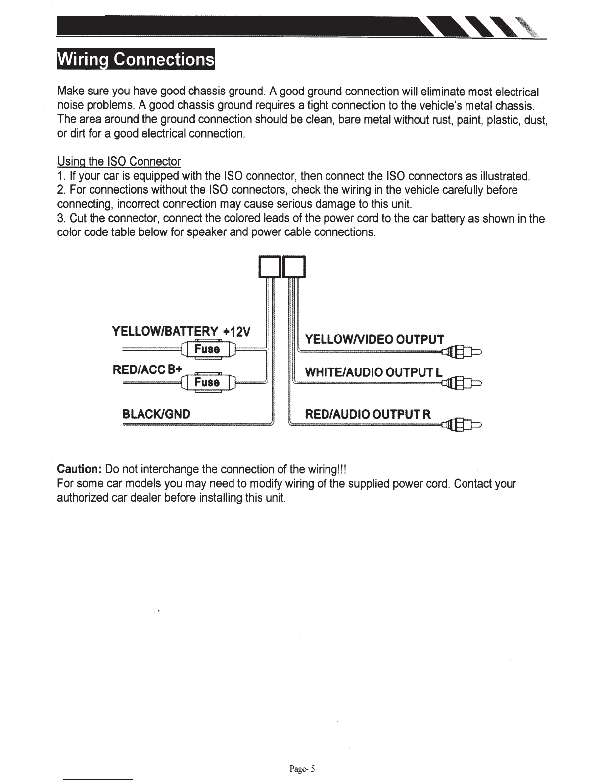
Using
1.
2.
connecting,
3.
color
the
If
your
car
For
connections
Cut
the
code
ISO
connector,
Connector
is
equipped
incorrect
table
below
without
with
the
the
ISO
connection
connect
for
the
speaker
may
YELLOW/BATTERY
BLACKIGND
ISO
connector,
connectors,
cause
colored
and
leads
power
+12V
then
connect
check
serious
of
cable
the
damage
the
power
connections.
YELLOWNIDEO
~
~=-=-=-------~
WHITE/AUDIO
RED/AUDIO
wiring
to
cord
the
ISO
connectors
in
the
vehicle
this
unit.
to
the
OUTPUT
OUTPUT
OUTPUT
car
R
as
carefully
battery
L
illustrated.
before
as
shown
in
the
Caution:
For
some
authorized
Do
car
car
not
interchange
models
dealer
you
may
before
the
connection
need
to
installing
modify
this
unit.
of
the
wiring
wiring!!!
of
the
supplied
power
cord.
Contact
your
Page-
5
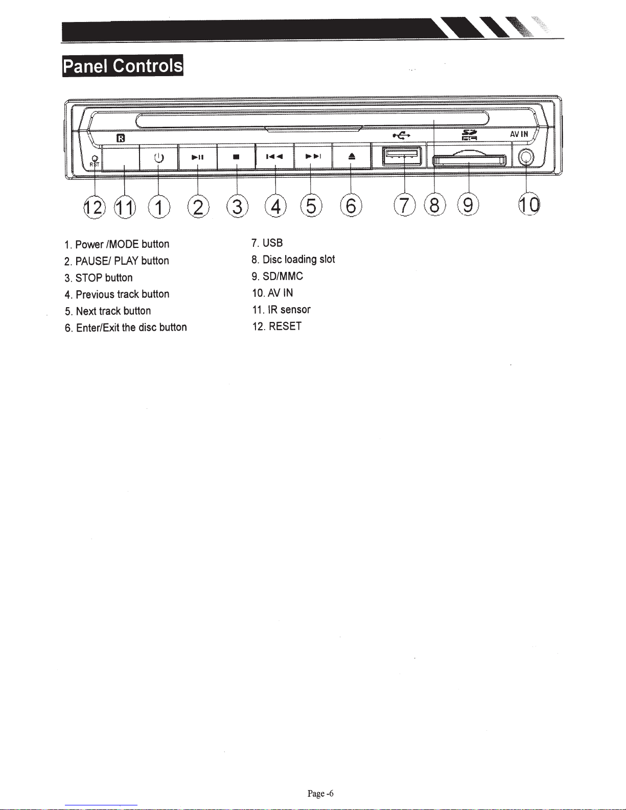
Panel
Power
1.
PAUSE/
2.
STOP
3.
Previous
4.
track
Next
5.
Enter/Exit
6.
Controls
PLAY
track
button
the
button
button
button
disc
button
/MODE
button
USB
7.
Disc
8.
SD/MMC
9.
AV
10.
IR
11.
RESET
12.
loading
IN
sensor
slot
Page-6
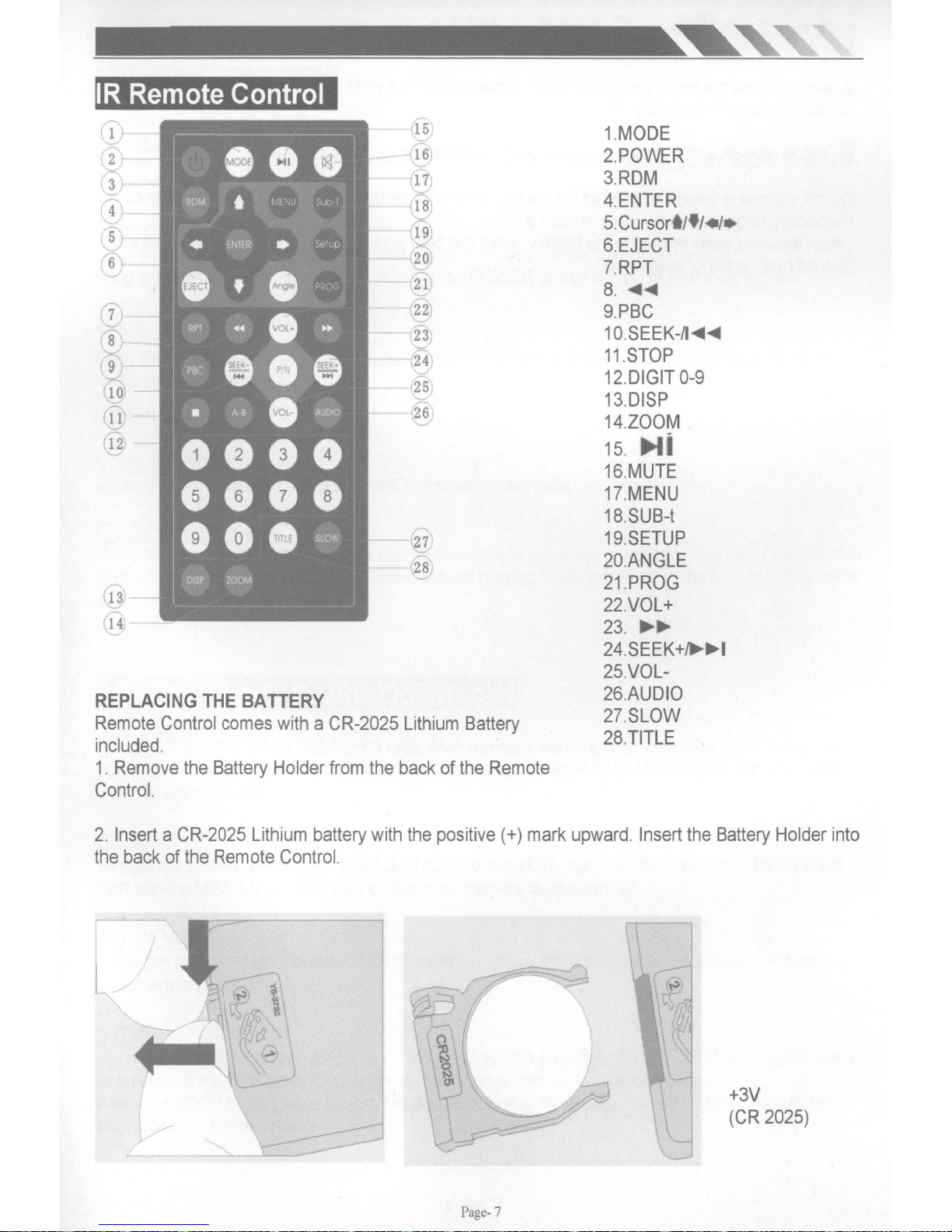
IR
Remote
REPLACING
Remote
included.
1.
Remove
Control.
Control
the
Control
THE
BATIERY
comes
Battery
with a CR-2025
Holder
from
the
Lithium
back
of
Battery
the
Remote
1.MODE
2.
POWER
3.RDM
4.ENTER
5.
Cursort/f/•1•
6.EJECT
7.RPT
8 .
........
9.PBC
1
O.SEEK-11
11.STOP
12.DIGIT
13.DISP
14.ZOOM
15
....
16.MUTE
17.MENU
18.SUB-t
19.SETUP
20.ANGLE
21.PROG
22.VOL+
23
.....
24.SEEK+
25.VOL-
26.AUDIO
27.SLOW
28.TITLE
........
0-9
.
...
I
2.
Insert a CR-2025
the
back
of
the
Lithium
Remote
battery
Control.
with
the
positive(+)
Page-
mark
upward. Insert
7
the
Battery
+3V
(CR
2025)
Holder
into
 Loading...