

Soundstream USA-204, USA-364 Owner's Manual And Installation Manual
28
SOUNDSTREAM TECHNOLOGIES
120 Blue Ravine Road Folsom California 95630 USA
ph 916.351.1288 fax 916.351.0414 ver. 1.17.96a
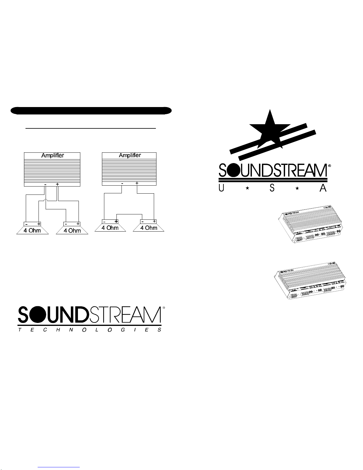
two 4 ohm woofers
in parallel = 2 ohms
two 4 ohm woofers
in series = 8 ohms
PARALLEL/SERIES WIRING DIAGRAMS
1
USA•204
&
USA•364
Power Amplifiers
OWNERS MANUAL AND
INSTALLATION GUIDE
2
CONGRATULATIONS!
You now own a Soundstream Amplifier, the result of a unique design and
engineering philosophy.
To maximize the performance of your system, we recommend that you
thoroughly acquaint yourself with its capabilities and features. Please retain
this manual and your sales and installation receipts for future reference.
Soundstream amplifiers are the result of American craftsmanship and the
highest quality control standards. When properly installed, they will provide
you with many years of listening pleasure. Please record the following
information which will help protect your investment should your amplifier ever
need replacement or service.
Serial # __________________________________________________
Dealer's Name _____________________________________________
Date of Purchase ___________________________________________
Installation Shop ___________________________________________
Installation Date ____________________________________________
CAUTION!
Prolonged listening at high levels may result in hearing loss.
Even though your new Soundstream amplifier sounds better than
anything you’ve ever heard, exercise caution to prevent hearing
damage.
27
SPECIFICATIONS
POWER OUTPUT
CROSSOVER SPECIFICATIONS
High Pass: 12 dB/octave, factory set at 150 Hz
Low Pass: 12 dB/octave, factory set at 75 Hz
DIMENSIONS
USA•204: 10-1/8" W x 8-3/16" D x 2-3/16" H
USA•364: 13-1/8" W x 8-3/16" D x 2-3/16" H
SERVICE
Your Soundstream amplifier is protected by a limited warranty. Please read
the enclosed warranty card.
THD < 0.1%
Signal to Noise > 90 dB
Frequency Response 20 Hz to 20 kHz +/- 0.5 dB
Stereo Separation > 90 dB
Damping > 200
Input Sensitivity 100 mV - 2.5 V
Input Impedance 12 k ohms
Stereo Power
4 ohms
Stereo Power
2 ohms
Bridged Power
4 ohms
USA•204
40w x 4 60w x 4
100w x 2
USA•364
60w x 4 90w x 4
180w x 2

26
PROTECTION CIRCUITRY
Your USA amplifier is protected against both overheating and short circuits by
means of the following circuits:
• Main power supply fuses.
• Speaker output circuit breakers.
• A fail-safe thermal protection circuit activating at 95°C.
NOTE: If you experience blown main power supply fuses, DO NOT increase
values beyond the original values! Doing so will void your warranty and may
damage your amplifier.
TROUBLESHOOTING
PROBLEM CAUSE
No sound and LED is not lit
• no power or ground at amp
• no remote turn-on signal
• blown fuse near battery
• blown amp power supply fuse
Repeatedly blown amp fuse, frequent activation of Thermal Protection Circuit
• check speaker configuration—
impedance may be less than 2
ohms stereo or 4 ohms mono
• speaker or leads may be shorted
• verify adequate amplifier ventila-
tion
3
TABLE OF CONTENTS
USA•204 Diagram ....................................................... 4 - 5
USA•364 Diagram ....................................................... 6 - 7
Features ........................................................................... 8
Crossover Modes ............................................................. 9
Crossover Adjustments ................................................. 10
Selecting Input Modes .................................................... 11
Wiring & Wiring Diagram ......................................... 12 - 13
Installation and Mounting ............................................... 14
Level Setting .................................................................. 15
Sample Systems ..................................................... 16 - 25
Protection Circuitry & Troubleshooting ........................... 26
Service ........................................................................... 27
Specifications ................................................................. 27
4
USA•204
25
USA•364
24
USA•364
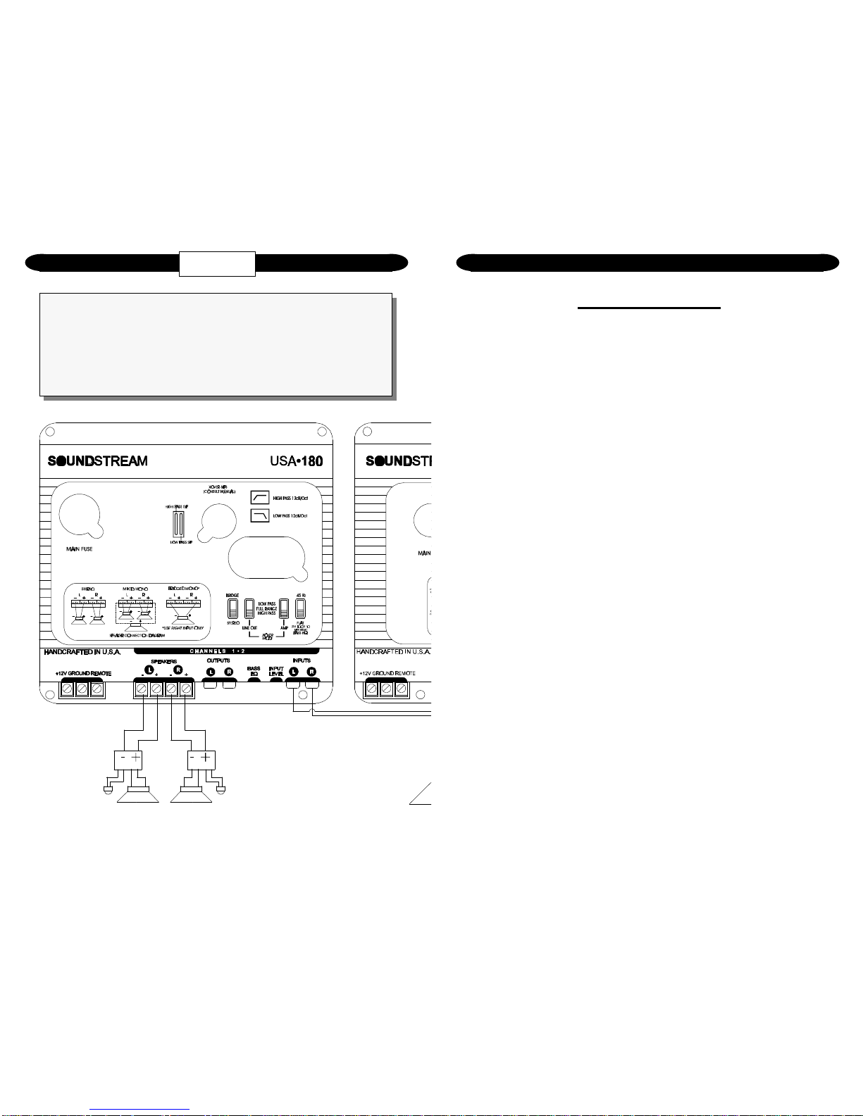
System Configuration #4:
• One pair of stereo inputs
• Two bridged channels of low pass operation driving subwoofers
• Bass EQ engaged
• High pass RCA output to an external amplifier driving satellites
• Internal crossovers used
5
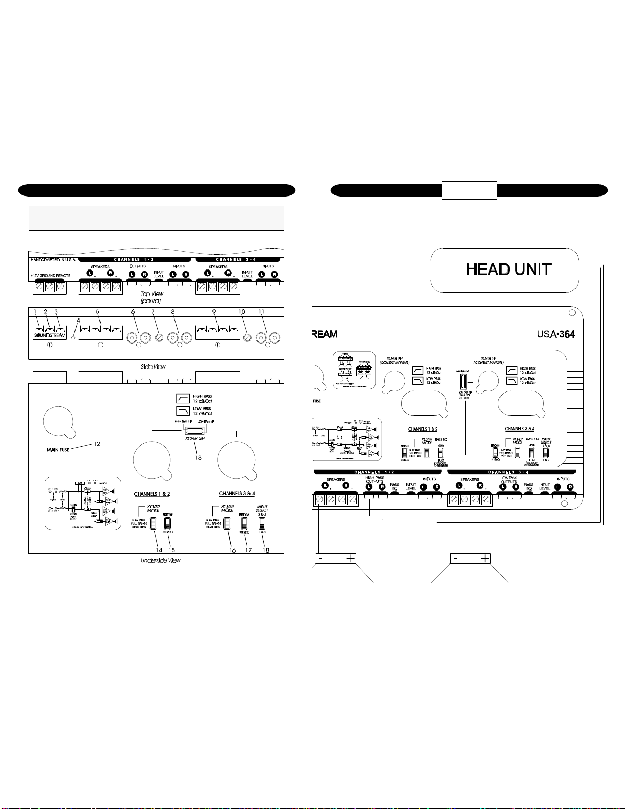
Key to Callouts
1. +12V - Connected to fuse or circuit breaker, then battery’s positive post.
2. Ground - Main ground connection. Bolt to a clean chassis ground in the
vehicle.
3. Remote - Remote turn-on input from the head unit. Accepts +12V.
4. LED - Indicates amplifier power on.
5. Speaker Output Connections - Channels 1 & 2.
6. Signal Output - Channels 1 & 2; low level full range output to an auxiliary
amplifier.
7. Input Level - Channels 1 & 2; variable from 100mV to 2.5V.
8. Inputs - Channels 1 & 2; right and left channel inputs; only right channel
input used in “Mono” mode.
9. Speaker Output Connections - Channels 3 & 4.
10. Input Level - Channels 3 & 4; variable from 100mV to 2.5V.
11. Inputs - Channels 3 & 4; right and left channel inputs; only right channel
input used in “Mono” mode.
12. [underside] Main Fuse - Main power supply fuse. Replace only with
same fuse value.
13. [underside] Crossover S.I.P.s - Crossover frequency settings for
amplifier.
14. [underside] Amplifier Crossover - Channels 1 & 2; Select high pass, low
pass, or full range operation.
15. [underside] Stereo/Bridged Mono Switch - Channels 1 & 2; Select
"Bridge" for bridged mono operation (use right channel input) or "Stereo"
for 2-channel Stereo or Mixed Mono operation.
16. [underside] Amplifier Crossover - Channels 3 & 4; Select high pass, low
pass, or full range operation.
17. [underside] Stereo/Bridged Mono Switch - Channels 3 & 4; Select
"Bridge" for bridged mono operation (use right channel input) or "Stereo"
for 2-channel Stereo or Mixed Mono operation.
18. [underside] Input Select - Channels 3 & 4; selectable inputs from internal
(from channels 1 & 2) or external.
 Loading...