

Soundstream Tarantula Limited Edition Owner's Manual And Installation Manual

OWNER’S MANUAL
and
INSTALLATION
GUIDE
CONGRA
TULA
TTONS!
You
now own the
Limited Edition Tarantula Amplifier,
the product of an uncompromising design and engineering philosophy. Your Soundstream Tarantula will outperform any other amplifier in the world.
To maximize the performance of your system, we recommend that you thoroughly
acquaint yourself with its capabilities and features.
Please retain this manual and your
sales receipt for future reference.
Soundstream amplifiers are the result of American innovation and the highest quality
control standards. When properly installed, they will provide you with many years
of listening pleasure. Should your amplifier ever need service or replacement due
to theft, please record the following information which will help protect your investment.
Serial
#
Dealer’s Name
Date of Purchase
Installation Shop
Installation Date
2

TABLE OF CONTENTS
Features.. .................................................................................................
p 4-5
Tarantula
Diagram
...................................................................................
p 6-7
Balanced/Unbalanced
Inputs
.....................................................................
p 8
Wiring
.......................................................................................................
P9
Installation
and
Mounting
.........................................................................
p
10
Crossover Adjustments
............................................................................
p
11
Hawkins Bass
ControlTM
Theory and
Use
................................................
p
12-13
Level Setting
............................................................................................
p
14
Large Mouth
Bass
....................................................................................
p
15
Power Supply Programming..
...................................................................
p
16
Troubleshooting Chart
...............................................................................
p 16
Sample System..
.......................................................................................
p
17
Protection Circuitry.. ..................................................................................
p
18
Very Serious Warnings
..............................................................................
p
18
Service .....................................................................................................
p 18
Specifications
...........................................................................................
p
19
3
FEA WE5
l
l
l
l
l
l
l
4
4
RUBW (_Rapid-Use
Branched
Impulse) This new proprietary power supply topol-
ogy eliminates “power sags”
d&g
low frequency reproduction by rapidly increasing the duty cycle, stabilizing the power supply and allowing it to deliver the power
required when reproducing low frequencies. Also, greater reserve gate power is
stored for low voltage conditions that occur during extreme conditions.
STACTTM
(STabilized Apex Current Topology) Reduces power supply stress
by 50%.
InThe
STACT design, inversion is done at the power amplifier drive
stage. Since the fully symmetrical power amplifier produces no even-harmonic
distortion itself and all preamplifier circuitry is run completely inphase, no even
harmonicdistortion phase reversal occurs and power is
better
distributed
through-
out the amplifier.
Advanced
TridentTM
Protection Topology Protects against potential harm/dam-
age in the following situations:
1. Output Protection against short circuits or improper loads.
2. Voltage Inconsistencies protects against ground fault (speaker shorts to vehicle
chassis) and an under/over voltage condition on the battery input.
3. Thermal Protection puts the amplifier into thermal rollback or shuts the amplifier down in extreme thermal conditions.
Tone Sweep Calibration Routine Automatically configures and optimizes the
power supply to the connected speaker load.
Hawkins Bass Control Provides a focused parametric subwoofer boost (0 to
+9
dB between 13-70 Hz) and routes otherwise wasted amplifier power back to
the audible bandwidth.
Continuously Variable Crossover Networks 24 dB/octave low pass crossovers variable from 35 Hz to 500 Hz with a range selection switch.
Input Level Indicator A three colored LED that provides visual confirmation of
the amplifier’s input level sensitivity setting.
Output Clipping Indicators Indicates clipping on the output stage of the amplifier. Monitoring the clipping indicators allows the user to achieve maximum
SPL without clipping the amplifier.
Large Mouth Bass Remote subwoofer volume control built into the amplifier.
4
FEA TURES
Output Phase Switch O-180 degree phase control switch.
Blue Neon Back lighting with four different selectable modes of operation,
including an audio response mode.
Fan Cooling With thermally sensitive speed control.
Differentially Balanced RCA Input Eliminates ground loop related noise in
the audio signal.
Fully Balanced 6-pin DIN Input For professional quality performance and
noise cancellation. The g-pin DIN plug carries
(*)
signal information for left
and right channels, audio ground, and &15Vdc to operate the Soundstream
BLT I BLT4 Balanced Line Transmitters and Balanced X.0 crossover.
RCA Line Output Provides a full range signal output to drive other amplifiers.
Wire Connections Power and ground connections accept
I\0
gauge cable,
while the speaker connections utilize dual 4 gauge connections.
Harmonic Bass AlignmentTM The 2nd and 3rd order harmonic peaks are critically aligned to fundamental peaks at low frequencies. This produces tighter,
more accurate bass reproduction.
Symmetrical Discrete Balanced Class A Drive Boards Auto-adjust for linear
performance while driving low impedance loads.
Drive Delay
llTM
Amplifier section powers up 2 to 3 seconds after the power
supply, eliminating turn-on pops. Turn off process is reversed; amplifier section turns off first, followed by the power supply.
ChassisinkTM All transistors are ideally located and sandwiched between the
circuit board and the heatsink to provide cool efficient amplifier operation.
Dynamically Optimized Power Grid
TM
Power grid is evenly distributed be-
tween primary and secondary power supplies, providing greater dynamics and
improved RF filtering.
5

TARANTULA DIAGRAM
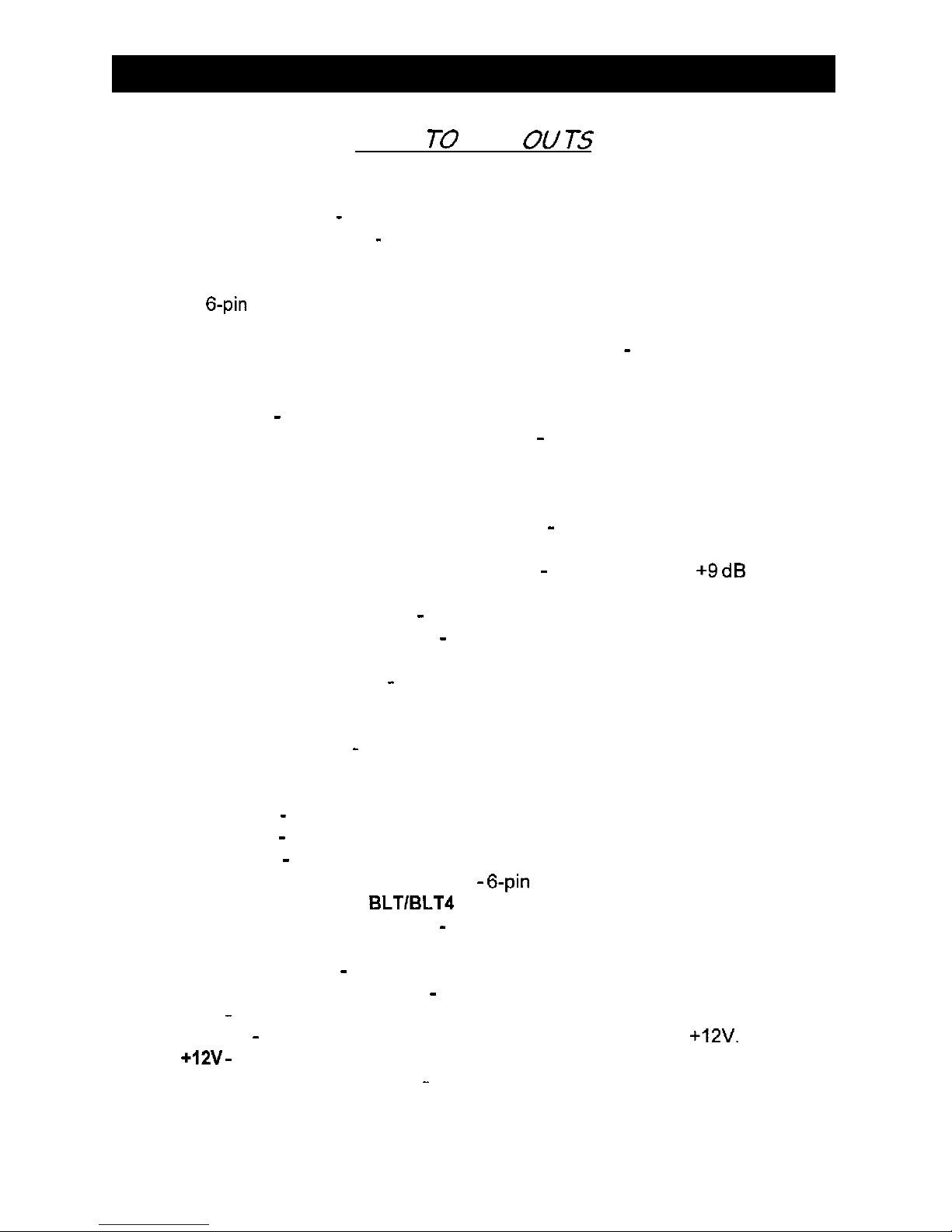
KEY
TO
CALL
OU
TS
1.
2.
3.
4.
5.
6.
7.
8.
9.
19.
11.
12.
13.
14.
15.
16.
17.
18.
19.
20.
21.
22.
23.
24.
25.
input
Level LED -Warns of the onset of clipping.
Amplifier Clip LED - Indicates clipped amplifier output.
Remote Volume Switch - Select “IN” when the LMB is used and “OUT” when
not in use.
Left Channel Balanced/Unbalanced Input Switch -Select “Balanced” to use
the
6-pin
balanced signal input. Select “Unbalanced” to use the RCA signal
inputs.
Right Channel Balanced/Unbalanced Input Switch - Select “Balanced” to
use the 6-pin balanced signal input. Select “Unbalanced” to use the RCA
signal inputs.
Input Level - Input level control.
Hawkins Bass Control/Subsonic Switch - Select “SUBSONIC” to engage
the Subsonic filter between 13 Hz and 30 Hz with no boost. Select “Hawkins
Bass Control” to engage the Subsonic filter between 30 Hz and 70 Hz with an
adjustable boost determined with the Q boost control.
Hawkins/Subsonic Frequency Adjustment - Frequency adjustment control
for the Hawkins Bass Control or the Subsonic filter.
Hawkins Bass Control Boost Adjustment - Varies from 0 to +Q dB of boost
when the Hawkins Bass Control circuit is engaged.
Low Pass Filter Adjustment - Frequency adjustment for the low pass filter.
Low Pass Filter Range Switch - Frequency range selection for the low pass
filter.
Power/Calibration Switch - Push button switch that selects power level or when
pushed and held for a short time, then released, the amplifier auto-adjust to the
speaker load.
Illumination Switch - Push button switch that allows the user to adjust the
light (OFF, ON, MUSIC or BLINK).
Phase Switch -Adjusts the speaker phase to either 0 or 180 degrees.
Power LED - Indicates amplifier power (see chart on page 16).
Status LED - Indicates amplifier status; thermal, short circuit, etc...
RCA Inputs - Right and Left channel RCA inputs.
Balanced Signal Input Connector -
6-pin
balanced input connector for use
with the Soundstream BLTIBLT4 Balanced Line Transmitter.
Large Mouth Bass Connector - Accepts the three prong plug that connects
the LMB remote volume control to the amplifier.
RCA Line Outputs - Right and Lefl channel RCA fullrange outputs.
Negative Speaker Terminals - Negative 4 gauge speaker connection.
GND - Main ground connection. Bolt to a clean chassis point in the vehicle.
Remote - Remote turn-on input from the head unit. Accepts +12V.
+12V - Connect to a fuse or circuit breaker, then to the battery’s positive terminal.
Positive Speaker Terminals - Positive 4 gauge speaker connection.
7
 Loading...