

Soundstream Tarantula ARS.1, ARS.2, Tarantula ARS.3 Installation Manual

FCC ID NOTICE
This device complies with Part 15 of the FCC rules. Operation is s
ubject to the following conditions:
1. This device may not cause harmful interference, and
2. This device must accept any interference received, including inte
rference that may cause undesired operation.
CAUTION: Changes or modifications not expressly approved by the part responsible for compliance void the user’s authority to operate
www.security.soundstream.com
this device.
INSTALLATION GUIDE
ARS.1
REMOTE STARTER & ALARM SYSTEM
REV.7

SYSTEM PROGRAMMING - Menu 1
PAGE 2
ARS.1
INSTALL MANUAL
TABLE OF CONTENTS
QUICK VIEW WIRING DIAGRAM..........................................................3-4
Connector Pin Configuration
Antenna Connector
Park Light Jumper
INSTALLATION NOTES............................................................................5
TACH LEARNING......................................................................................6
Data Tach Mode
Tach/ Tachless Learn
Hybrid Mode
QUICK VIEW PROGRAMMING..............................................................7-9
Enter Program Mode
System Reset
Menu 1,2,3 & 4 Quick View
SYSTEM WIRING DETAILS................................................................10-14
Connector Views
Wiring Description
SHOCK SENSOR.....................................................................................15
Adjusting Shock Sensor Sensitivity
TRANSMITTER PROGRAMMING...........................................................16
Adding/ Reprogramming Transmitter
DIAGNOSTICS.........................................................................................17
Diagnostic Chart
Diagnostic Memory
DOOR LOCK DIAGRAMS..................................................................18-19
Relay Diagrams
CONTACT INFORMATION.......................................................................20
SYSTEM PROGRAMMING - Menu 1
PAGE 3
ARS.1
INSTALL MANUAL
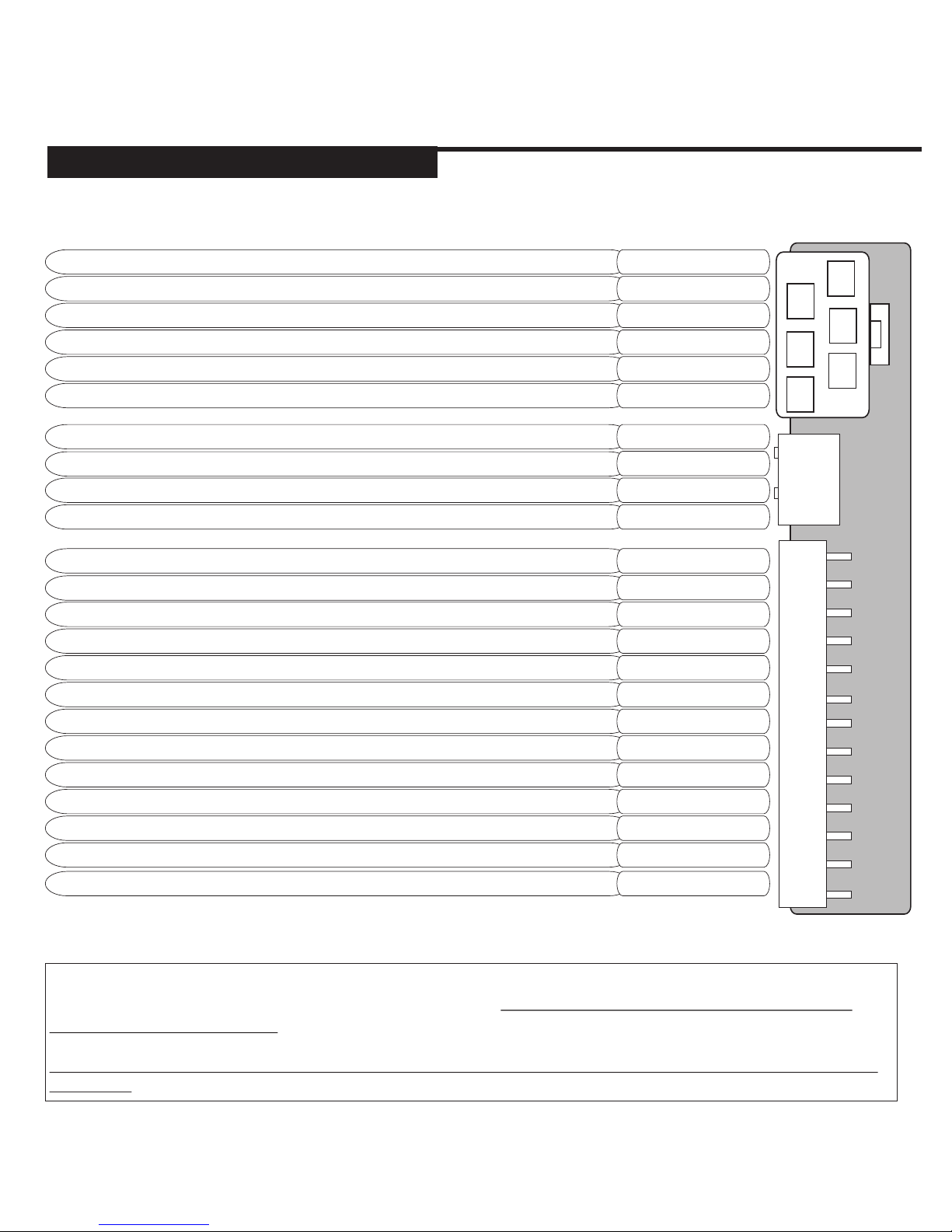
QUICK VIEW WIRE DIAGRAM
1
5
3
2
4
6
1
2
3
4
5
6
7
8
9
10
11
12
13
1
3
2
4
OUTPUT TO ACTIVATE IGNITION CIRCUITTHE
SELECTABLE OUTPUT* (DEFAULT 2ND IGN)
12VOLT/ 30 AMP MAIN POWER INPUT
OUTPUT TO ACTIVATE THE STARTER CIRCUIT
12VOLT/ 30 AMP MAIN POWER INPUT
OUTPUT TO ACTIVATE ACCESSORY CIRCUITTHE
SYSTEM GROUND INPUT
SELECTABLE PARK LIGHT OUTPUT (DEFAULT POSITIVE)
(+) SIREN OUTPUT/ (+) PULSED HORN OUTPUT
* The selectable output can be changed in the program mode to output as a 2nd Accessory or
2nd Start output. Default output is second ignition. This output does not change back to
2nd Ignition upon reset.
WARNING - NEVER INSTALL AN AUTOMATIC REMOTE STARTER INTO A MANUAL TRANSMISSION
VEHICLE!
BLACK
WHITE
ORANGE/BLACK
BROWN
PINK
PINK/WHITE
RED
PURPLE
RED
ORANGE
(-) STARTER KILL/ ANTI-GRIND OUTPUT
AUXILIARY 1 OUTPUT/ PROGRAMMABLE OUTPUT
(-) 2ND ACCESSORY/ PROGRAMMABLE AUXILIARY 2 OUTPUT
AUXILIARY OUTPUT TO ACTIVATE TRUNK RELEASE
REARM OUTPUT (PULSE WITH LOCK & AFTER START)
NEGATIVE SECOND START OUTPUT
DISARM OUTPUT (PULSE WITH UNLOCK & BEFORE START)
POSITIVE DOOR PIN INPUT/ POSITIVE WHEN OPENED
DIESEL WAIT TO START (+ or -) / TRIGGER TO START
TACH DETECTION INPUT (CONNECT TO COIL, INJECTOR...)
BRAKE SWITCH INPUT (12VOLT WHEN BRAKE IS PRESSED)
HOOD PIN SWITCH (GROUND WHEN HOOD IS OPENED)
NOT USED
NEGATIVE DOOR PIN INPUT/ NEGATIVE WHEN OPENED
ORANGE/BLACK
ORANGE/WHITE
RED/WHITE
GREEN/WHITE
PINK/WHITE
GREEN/BLACK
PURPLE
GRAY/BLACK
PURPLE/WHITE
GRAY
GREEN
BROWN
BLACK/WHITE
SYSTEM PROGRAMMING - Menu 1
PAGE 4
INSTALL MANUAL
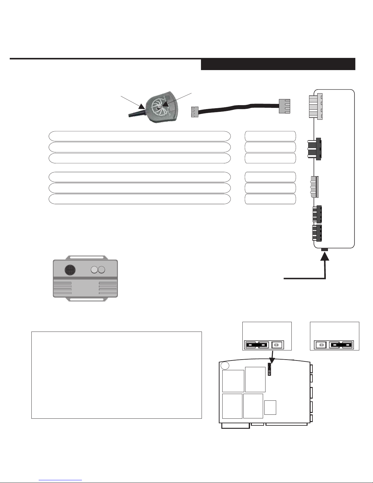
QUICK VIEW WIRE DIAGRAM
1
2
3
1
2
3
1
2
3
4
Position 1 or Position 2
GREEN
BLUE
N/A*
RED
BLACK
ORANGE
BYPASS MODULE DATA COMMUNICATION PORTS**
DUAL STAGE SHOCK SENSOR
The connector is located on the back of the module.
The default setting is set for FORTIN™ Bypass Modules.
1
2
3
4
SELECTABLE PARK LIGHT OUTPUT***
OUTPUT TO ACTIVATE DOOR LOCK CIRCUIT (-)
OUTPUT TO ACTIVATE DOOR UNLOCK CIRCUIT (-)
OUTPUT FOR VOLTAGE INVERTER*
12VOLT OUTPUT FOR BYPASS MODULE
GROUND OUTPUT FOR BYPASS MODULE
(-) WHILE RUNNING OUTPUT (BYPASS TURN ON)
BY DEFAULT THE SYSTEM COMES WITH
THE PARK LIGHT JUMPER SET FOR
POSITIVE PARK LIGHT OUTPUT.
TO CHANGE THE SYSTEM TO A NEGATIVE
PARK LIGHT OUTPUT, PLACE THE JUMPER
IN THE NEGATIVE PARK LIGHT POSITION
SHOWN IN THE DIAGRAM. (Position 2)
POSITIVE
PARK LIGHT
NEGATIVE
PARK LIGHT
ARS.1
+
-
1
2
3
4
Status LED
Program Button

SYSTEM PROGRAMMING - Menu 1
PAGE 5
INSTALL MANUAL
NOTES
PLEASE NOTE
* THE CENTRE PIN OF THE KEYLESS CONNECTOR IS LOW CURRENT AND IS
DESIGNED TO SUPPLY POWER TO DOOR LOCK MODULES (DO NOT CONNECT TO
RELAYS) OVERLOADING THIS OUTPUT WILL DAMAGE THE MODULE!
ONLY.
**THESE INPUT’S ARE USED TO CONNECT BYPASS MODULES AND OTHER
PRODUCTS SUCH AS GPS TRACKING. FOR BYPASS MODULES THERE ARE 2
SELECTION TYPES. THE DEFAULT SETTING IS FOR FORTIN™ MODULES. THE
SECOND IS FOR IDATA™ BYPASS MODULES.
***ALWAYS TEST AND CONFIRM THE PARK LIGHT POLARITY BEFORE MAKING
YOUR CONNECTION TO THE VEHICLE.
THIS MODEL IS TO BE INSTALLED IN AUTOMATIC TRANSMISSION
VEHICLES ONLY.
ARS.1
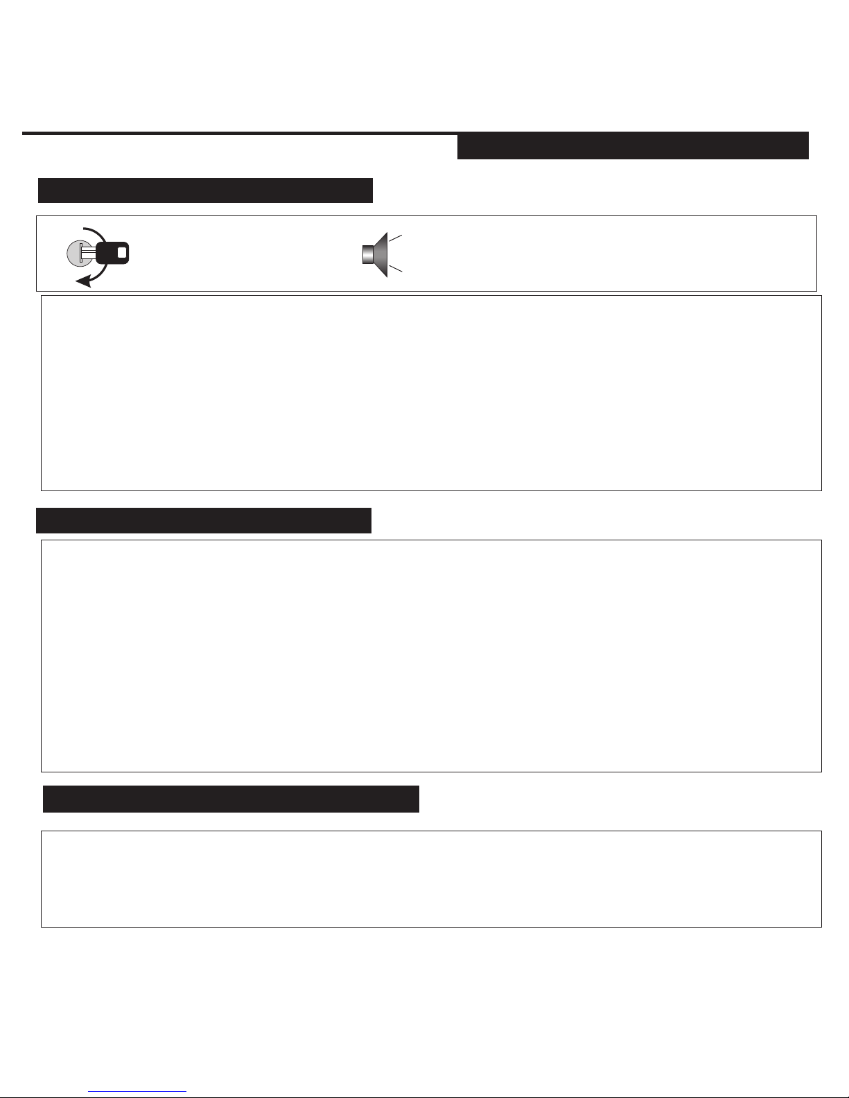
AUTO TACH/ TACHLESS LEARNING
Start the vehicle with
the ignition key.
2 CHIRPS/ 2 FLASHES = TACH MODE
NOTES:
When tach learning the system first sends out a request for tach from the data port. If it gets a
valid rpm response over 750 rpm then it goes into data tach mode (3 flashes). If there is no
response, the unit will look for the tach/tachless.
Once the starter goes on then off, the unit will learn tach, if there is no tach detected within a few
seconds after starting, the system will learn in tachless mode after 20 seconds.
If there is no starter detected, the system learns tach after 30 seconds. If no tach is detected the
system will learn tachless after an additional 10 seconds.
4 CHIRPS/ 4 FLASHES = TACHLESS MODE
3 CHIRPS/ 3 FLASHES = DATA TACH MODE
SYSTEM PROGRAMMING - Menu 1
PAGE 6
INSTALL MANUAL
SYSTEM WIRING DETAILS
HYBRID MODE‘S
Hybrid mode 1 - This option requires a tach connection. Once the vehicle starts the system will not monitor
the tach input and stay running for 15 minutes.
Hybrid Mode 2- (No Tach wire connection)This setting will power up the ignition wires, pulse the start output
for 2 seconds then stay on/ run for 15 minutes. See Program Menu 4, Hybrid Mode 1& 2. Hybrid mode 2 was
designed for hybrid vehicles that may not actually start until the battery voltage
drops.
**Hybrid Mode 2 is also ideal for vehicles with no starter wire or “Automatic Starting”. This is when the
vehicle’s starter motor will continue to crank and start the vehicle even if the key is only turned to the start
position momentarily.
“Push to Start” systems and
Hold the brake then start the vehicle with the key. Place the transmission into reverse to lower the
RPM. Press and release the button on the antenna twice. The system will chirp the Horn and
flash the park lights two times to confirm Tach Mode or chirp 4 times/ 4 flashes to indicate
Tachless Mode re-learn.
LOW IDLE LEARNING
ARS.1
 Loading...