

Soundstream Tarantula AL.2 Installation Manual
FCC ID NOTICE
This device complies with Part 15 of the FCC rules. Operation is s
ubject to the following conditions:
1. This device may not cause harmful interference, and
2. This device must accept any interference received, including inte
rference that may cause undesired operation.
CAUTION: Changes or modifications not expressly approved by the part responsible for compliance void the user’s authority to operate
www.security.soundstream.com
this device.
AL.2
AUTO SECURITY SYSTEM
INSTALLATION GUIDE
REV.5

Wire Diagram.................................................................Page 3
Program Mode...............................................................Page 4
Enter Program Mode
Programing Chart..........................................................Page 5
Program Menu 1 Page 5
Program Menu 2 Page 5
Wire Description...........................................................Page 6-8
Transmitter Programming.............................................Page 9
First and Second Car Operation
PAD LOC
Shock Sensor Programing...........................................Page 10
Increase Sensitivity
Decrease Sensitivity
Diagnostics....................................................................Page 11
Diagnostics Chart
Quick View Operation Chart........................................Page 12-13
Arm/ Disarm Alarm
Auxiliary Channels
Product Warranty..........................................................Page 15
Contact Information .....................................................Page 16
Anti Car Jack Mode......................................................Page 14
SYSTEM PROGRAMMING - Menu 1
PAGE 2
INSTALL MANUAL
TABLE OF CONTENTS
AL.2
SYSTEM PROGRAMMING - Menu 1
PAGE 3
INSTALL MANUAL
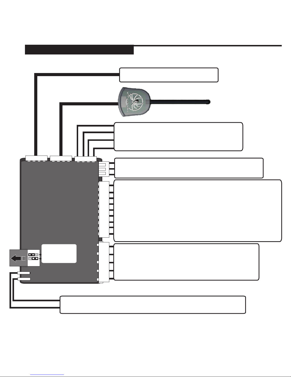
WIRE DIAGRAM
Pin 5 - WHITE - Park Light Output (+ or -)*
Pin 4 - RED/WHITE - Trunk Release (+ or -)**
Pin 3 - BLACK - Ground Input (-)
Pin 2 - RED - Constant 12volt Input (+)
Pin 1 - BROWN - Siren (+12V)
Pin 9 - WHITE/GREEN - 2nd Unlock / (-) When Disarmed
Pin 8 - BLUE - Trunk Switch (-)
Pin 7 - GREEN - Negative Door Pin Input (-)
Pin 6 - VIOLET - Positive Door Pin Input (+)
Pin 5 - YELLOW - Switched Ignition Input (+)
Pin 4 - BLACK/WHITE - Dome Light / Aux 3 Output
Pin 3 - ORANGE - Ground When Armed (-250mA)
Pin 2 - BROWN - Horn / Aux 2 Output (-250mA)
Pin 1 - WHITE/BLUE - Aux 1 Output (-250mA)
Optional Communication Port
LED / VALET Switch
RF Antenna
Pin 3 - Green - Negative Unlock Output (-250mA)
Pin 2 - Output for Voltage Inverter Only
Pin 1 - Blue - Negative Lock Output (-250mA)
Pin 2 - BROWN - Starter Disable Relay (Normally Connected)
Pin 1 - BROWN - Starter Disable Relay (Normally Connected)
Pin 4 - Red - 12volt Output for Sensor
Pin 3 - Black - Ground Output for Sensor
Pin 2 - Green - Full Alarm Trigger Input (-)
Pin 1 - Blue - Warn Away Trigger Input (-)
*Park Lights are Jumper Selectable. Default Positive.
**Trunk Release is Jumper Selectable. Default Negative.
AL.2
+ -
- +
Jumper ’s
Trunk Rel ease
Park Lig hts

1 - Cycle the Ignition Key On/Off On/Off On.
(Leave the key in the ON position)
2 - Press and release the Program Switch 1 time.
(*The Siren will chip to confirm that the system has entered Program Mode.)
*If the siren does not chirp repeat steps 1 & 2.
3 - Select the Program Menu.
-Press the Lock Button To Enter Menu 1.
-Press the Unlock Button to Enter Menu 2.
(*The Siren will chip to confirm that the system has entered the Menu.)
See the following page for Program Menus and Settings.
4 - Press and Release the Program Switch to advance through the settings.
(Each setting is Confirmed by Siren Chirps & LED flashes)
5 - Press and hold the Program Switch to change the setting.
(Confirmed by Siren Chirps*)
* One Chirp = Setting 1
**Two Chirps = Setting 2
***Three Chirps = Setting 3
6 - To exit Program Mode, turn ignition key off.
(Confirmed by Long Siren Chirp)
ENTERING PROGRAM MODE
SYSTEM PROGRAMMING - Menu 1
PAGE 4
INSTALL MANUAL
PROGRAM MODE
1 - Cycle the Ignition Key On/Off On/Off On.
(Leave the key in the ON position)
2 - Press and release the Program Switch 1 time.
(*The Siren will chip to confirm that the system has entered Program Mode.)
*If the siren does not chirp repeat steps 1 & 2.
3- Press and Hold the program switch until the siren chirps 3 times.
(The system is now reset to default settings)
SYSTEM RESET
AL.2
SYSTEM PROGRAMMING - Menu 1
PAGE 5
INSTALL MANUAL
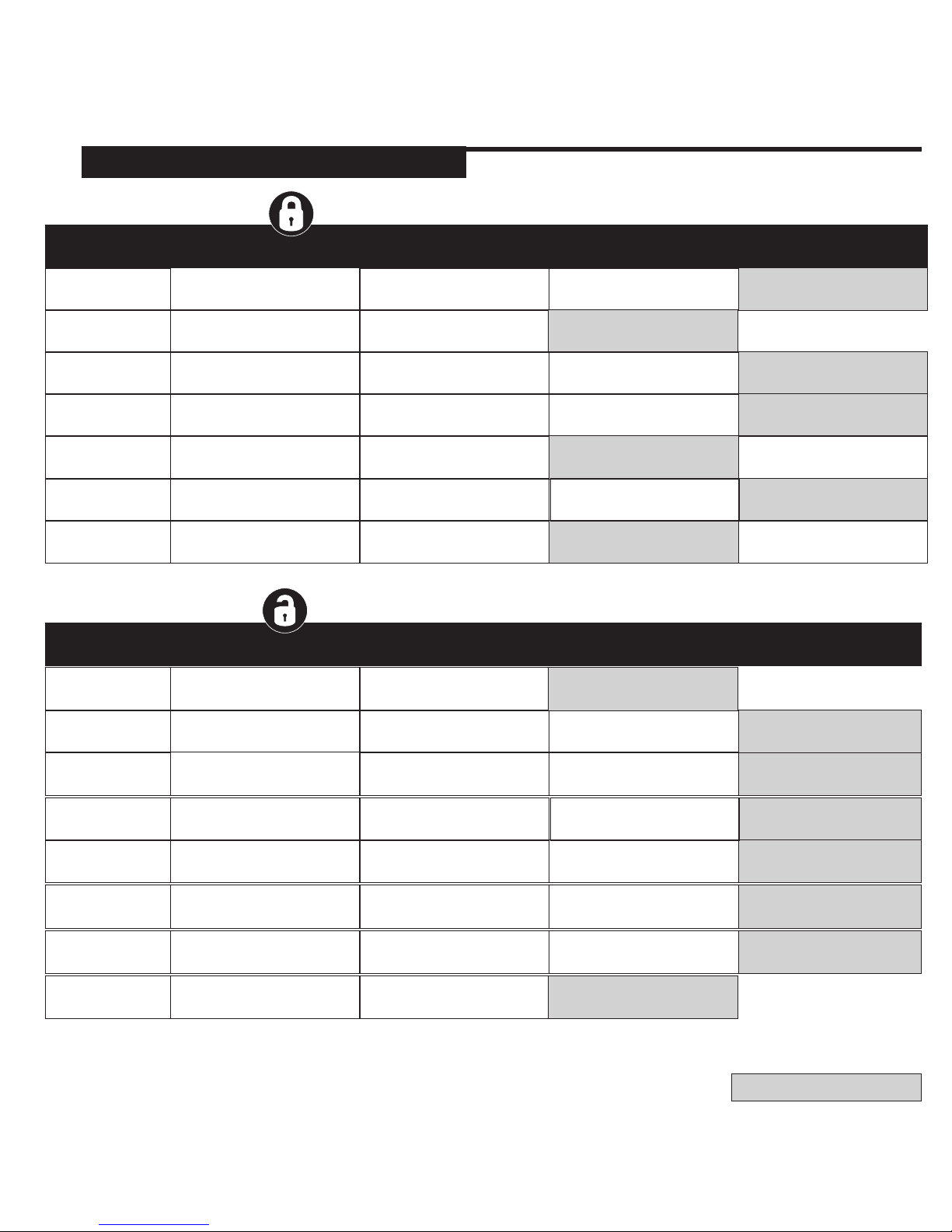
PROGRAM MODE
SETTING #
LED FLASHES
2
3
1
PARK LIGHT
OUTPUT
30 SECOND ON
FOR DISARM
N/A
OPTION 3
3 CHIRPS
OPTION 1
1 CHIRP
OPTION 2
2 CHIRPS
AUX 1
* BUTTON
VALET
SETTINGS
0.75 SECOND
PULSED OUTPUT
SECURE VALET
15 SECONDS
LATCHED
IGNITION ON RESET
ACTIVE WHILE
BUTTON IS HELD
STANDARD VALET
8 SECONDS
SETTING
DESCRIPTION
SETTING #
LED FLASHES
1
2
3
4
5
6
7
IGNITION
AUTO-LOCK
IGNITION AUTO-LOCK &
UNLOCK ENABLED
IGNITION AUTO-LOCK
ONLY
OPTION 3
3 CHIRPS
IGNITION AUTO-LOCK
DISABLED
OPTION 1
1 CHIRP
OPTION 2
2 CHIRPS
SIREN SETTINGS
DOOR LOCK
OPTIONS
DOOR LOCK
PULSE TIMES
SHOCK SENSOR
SETTINGS
PASSIVE ARMING
PASSIVE
DOOR LOCKS
SIREN CHIRPS
DISABLED
DOUBLE UNLOCK /
SINGLE LOCK PULSES
0.25 SECOND
PULSES
SENSOR DISABLED
FULL
PASSIVE ARMING
PASSIVE DOOR LOCKS
DISABLED
DOUBLE LOCK /
SINGLE UNLOCK PULSES
3 SECOND
PULSES
SENSOR ENABLED
PASSIVE DOOR LOCKS
ENABLED
SIREN CHIRPS
ENABLED
SINGLE UNLOCK /
SINGLE LOCK PULSES
0.75 SECOND
PULSES
ALL PASSIVE ARMING
DISABLED
SETTING
DESCRIPTION
PROGRAM MODE 1
PROGRAM MODE 2
4
5
ANIT-CAR JACK MODE
OPTIONS
HORN OUTPUT
TIMING
CAR JACK MODE 1
50mS HORN
OUTPUT
20mS HORN
OUTPUT
CAR JACK MODE
DISABLED
10mS HORN
OUTPUT
6
AUX 2 (HORN / AUX)
UNLOCK & TRUNK
0.75 SEC
PULSED OUTPUT
ACTIVE WHILE BUTTON
IS HELD
HORN OUTPUT &
CAR FINDER (UNLOCK & *)
7
AUX 3 (DOME LIGHT)
* & TRUNK BUTTON
0.75 SEC
PULSED OUTPUT
ACTIVE WHILE BUTTON
IS HELD
DOME LIGHT OUTPUT
8
2ND UNLOCK/ (-) WHEN
DISARMED
GROUND WHEN
DISARMED
SECOND UNLOCK
OUTPUT
PASSIVE SAFETY
REARM ONLY
NORMAL OPERATION
CAR JACK MODE 2
AL.2
= DEFAULT SETTING
 Loading...