

Soundstream SDR-342B, SDR-342BT Owner's Manual
SDR-342BT
SDR-342B
Flip-down/Detachable 3.4" Monitor
MP3/MP4 Player
AM/FMRadio
I
Built-in
TV
tuner
(only for SDR-342T model)
Owner's Manual
through
read
Take the time
Familiarity
Performance from
to
installation
with
new device.
your
owner's
this
and operation procedures
manual.
will help
you obtain the best

Using the device at temperature below
•
-1
may cause the breakage
OOC
the device.
of
BEFORE USING
PLEASE HEAT UP THE
PASSENGER
COMPARTMENT
TO THE
RECOMMENDED TEMPERATURE!
•
Read
carefully
• Disconnect the
When replacing the fuse, be sure to use one with an identical amperage rating. Using a fuse
•
with a higher
Make sure that pins or other foreign objects do not get inside
•
through this manual to familiarize you with this high-quality sound system.
vehicle's negative battery terminal while mounting and connecting the unit.
amperage·
rating may cause serious damage to the unit.
the unit; they may cause
malfunctions, or create safety hazards such as electrical shock or laser beam exposure.
hot or cold weather, wait until the temperature
you have parked the car for a long time
• If
in
the car becomes normal before operating the unit.
• DO NOT
open covers and do not repair yourself. Consult the dealer or an experienced
technician for help.
not use the system for a long
Make sure you disconnect the power supply and aerial if you
•
will
period or during a thunderstorm.
• Make sure you disconnect the power supply if the system appears to be working incorrectly,
in
(For example: making unusual sounds,
Have a qualified technician check the system.
liquid having gotten inside
it)
• The unit is designed for negative terminal
metal. Please confirm it before
the speaker wires to be shorted together when the unit is switched on. Otherwise
•
Do not
allow
installation.
smelling
of
it may overload or burn out the power amplifier.
Do not
•
Don't remove the detachable panel when encoding.
•
install
the detachable panel before connecting the wire.
strange, emitting smokes from inside or
the battery, which is connected to the
vehicle
2
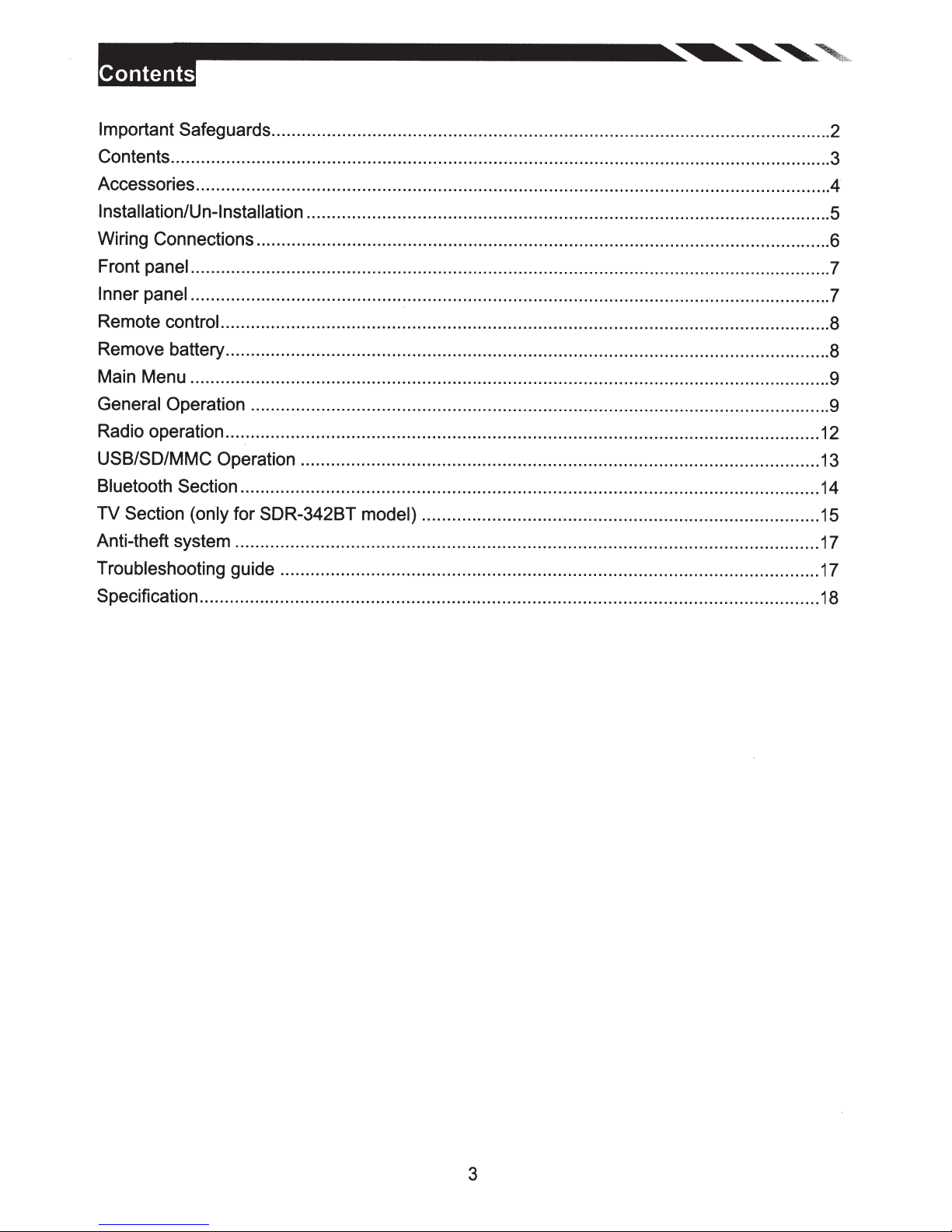
Important Safeguards ............................................................................................................... 2
Contents ................................................................................................................................... 3
Accessories .............................................................................................................................. 4
lnstallation/Un-lnstallation
........................................................................................................ 5
Wiring Connections .................................................................................................................. 6
Front panel
............................................................................................................................... 7
Inner panel ............................................................................................................................... 7
Remote
control
......................................................................................................................... 8
Remove battery ........................................................................................................................ 8
Main Menu ............................................................................................................................... 9
General
Operation
................................................................................................................... 9
Radio operation ...................................................................................................................... 12
USB/SD/MMC
Bluetooth
TV Section
Operation ....................................................................................................... 13
Section ................................................................................................................... 14
(only for SDR-342BT
model)
............................................................................... 15
Anti-theft system .................................................................................................................... 17
Troubleshooting guide ........................................................................................................... 17
Specification ........................................................................................................................... 18
3
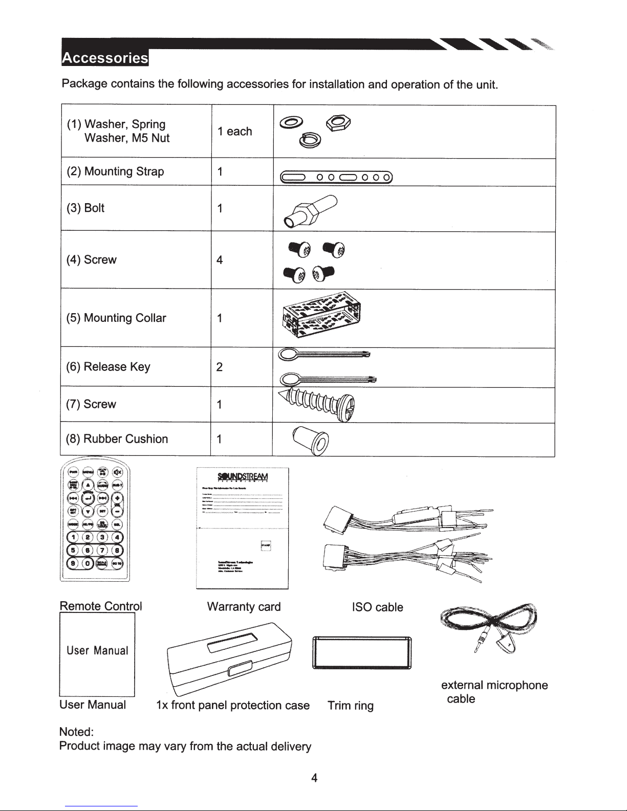
Package contains the
following
accessories for
installation
and operation
of
the unit.
(1) Washer,
Washer, M5 Nut
(2) Mounting
(3)
Bolt
(4)
Screw
(5) Mounting
(6)
Release
(7)
Screw
Spring
Strap
Collar
Key
1
1
1
4
1
2
1
each
p
o o
c:::>
o o
o)
(8) Rubber Cushion
·-·
------·------
--·---··-
·-
-·---·-
·
Remote
User
User
Noted:
Product image may vary from the
Control
Manual
Manual
1 x front
1
Warranty card
panel
ISO cable
~
protection case Trim ring
actual delivery
II
external
cable
microphone
4
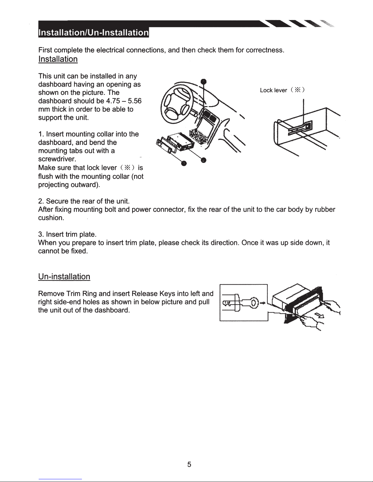
First complete the electrical connections, and then check them for correctness.
Installation
This unit can be installed
dashboard having an opening as
shown on the picture. The
dashboard should be
mm thick
support the unit.
1.
Insert mounting collar into the
dashboard, and bend the
mounting tabs out with a
screwdriver.
Make sure that lock lever C
flush with the mounting collar (not
projecting outward).
2.
Secure the rear
After fixing mounting bolt and power connector, fix the rear
cushion.
3.
Insert trim plate.
When you prepare to insert trim plate, please check its direction. Once it was up side down, it
cannot be fixed.
in
order to be able to
of
in
any
4.
75 - 5.56
*)
the unit.
is
Lock lever ( * )
of
the unit to the car body by rubber
U n-installation
Remove Trim Ring and insert Release Keys into left and
right side-end holes as shown
the unit out
of
the dashboard.
in
below picture and pull 0
~
..
5
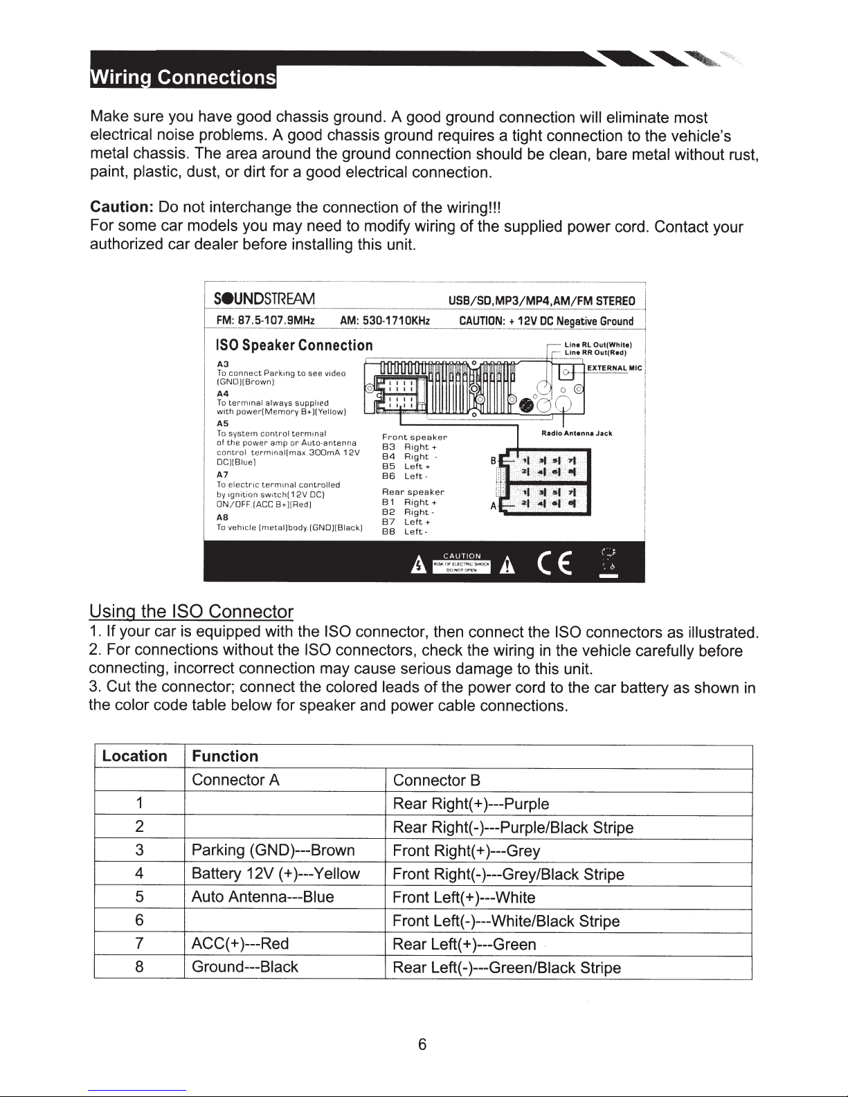
Make sure you have good chassis ground. A good ground connection
will eliminate
most
electrical noise problems. A good chassis ground requires a tight connection to the vehicle's
metal chassis. The area around the ground connection should be clean, bare metal without rust,
paint, plastic, dust, or dirt for a good electrical connection.
Caution:
Do not interchange the connection of the wiring!!!
For some car models you may need to modify wiring
authorized car dealer before
installing
this unit.
SeUNDSTREAM
ISO
AJ
To
co
nn
(GNOJ[B
A4
To
te
rmin
wi
th
pow
A5
To
sys
of
the
contr
DC)(
Blue)
A7
To
el
ec
by
ign
ON/
OF
AS
To
v
ehicl
Speaker
ect
ro
al
er
tem
pow
ol
ter
tric
it
ion
F(
ACC B +](R ed )
e (
Pa
rking t o se e vi
wn)
alw
ays supplied
(M
em
or y
contr
ol
er
a
mp
mmal(
max.
termina
switch(
meta
l)b
Connection
deo
B+)(Yell
ow
)
ter
mi
nal
or
Au
to
-an
tenna
30DmA
12V
l con
tr
oll ed
1
2V
DC)
ody.(GNO)(Biack)
FJnWID~
Fr
83
84
85
86
Rear
81
82
87
88
ont
speaker
Ri
gh
Ri
ght
Left+
Left
speaker
Ri
ght+
Ri
ght
Left+
Left-
~
mm~
t +
-
-
-
of
the supplied power cord. Contact your
USB/SD,MP3/MP4,AM/FM
immrr==n
~r
+-+-
STEREO
--
Using the ISO
1.
If
your car is equipped with the
2.
For connections without the
Connector
ISO
connector, then connect the
ISO connectors, check the wiring
ISO
in
the vehicle
connecting, incorrect connection may cause serious damage to this unit.
3.
Cut the connector; connect the colored leads
of
the power cord to the car battery as shown
the color code table below for speaker and power cable connections.
Location Function
Connector A Connector B
1
2
3
4
5
6
7
8
Parking (GND)---Brown
Battery 12V
(+)---Yellow
Auto Antenna---Blue
ACC(
+)---Red
Ground---Black
Rear Right(+ )---Purple
Rear Right(-)---Purple/Black Stripe
Front Right(+ )---Grey
Front Right(-)---Grey/Black Stripe
Front Left(+ )---White
Front Left(- )---White/Black Stripe
Rear Left(+ )---Green
Rear Left(-)---Green/Black Stripe
connectors as illustrated.
carefully
before
in
6

f-l:!::::i!~
--t
1
--t---
2
3
----.~
4
6 7 8 9
10
14
1)
2)
3)
4)
5)
6)
7)
8)
9)
Power
EQ
SEL
Mode button
SCAN
MENU button
Volume/OK
AS/PS
BAND
/Mute button
/LOUD
button
button
button
I
Inner panel
18
[
SD (
)
@
11
button
button
Media select
0
, B
12
accept button
I
L.__j
13
10
11)
12
13
14
15
16
17)
19
~(]
)
Play/Pause,
Previous
)
Next
)
)
)
)
sensor
IR
LCD Screen
OPEN
USB slot
AUXIN
20
0
Memory /reject button
Reverse button
I
Forward button
I
button
jack/AV
L.__j
D
jack(optional)
IN
0
0
B
J
mUm
~@
[
~
slot
18)
19)
20
NOTE:
The power
SD/MMC
Reset button
Anti-Theft LED flash
)
When turn
card
light will
the power, the unit
off
continue lighting.
switch to standby mode
will
7
unless
cut the
@s
ACC power.
J
~!~~!!~
.................
~
~
~
G)--~~===-::1
---
©
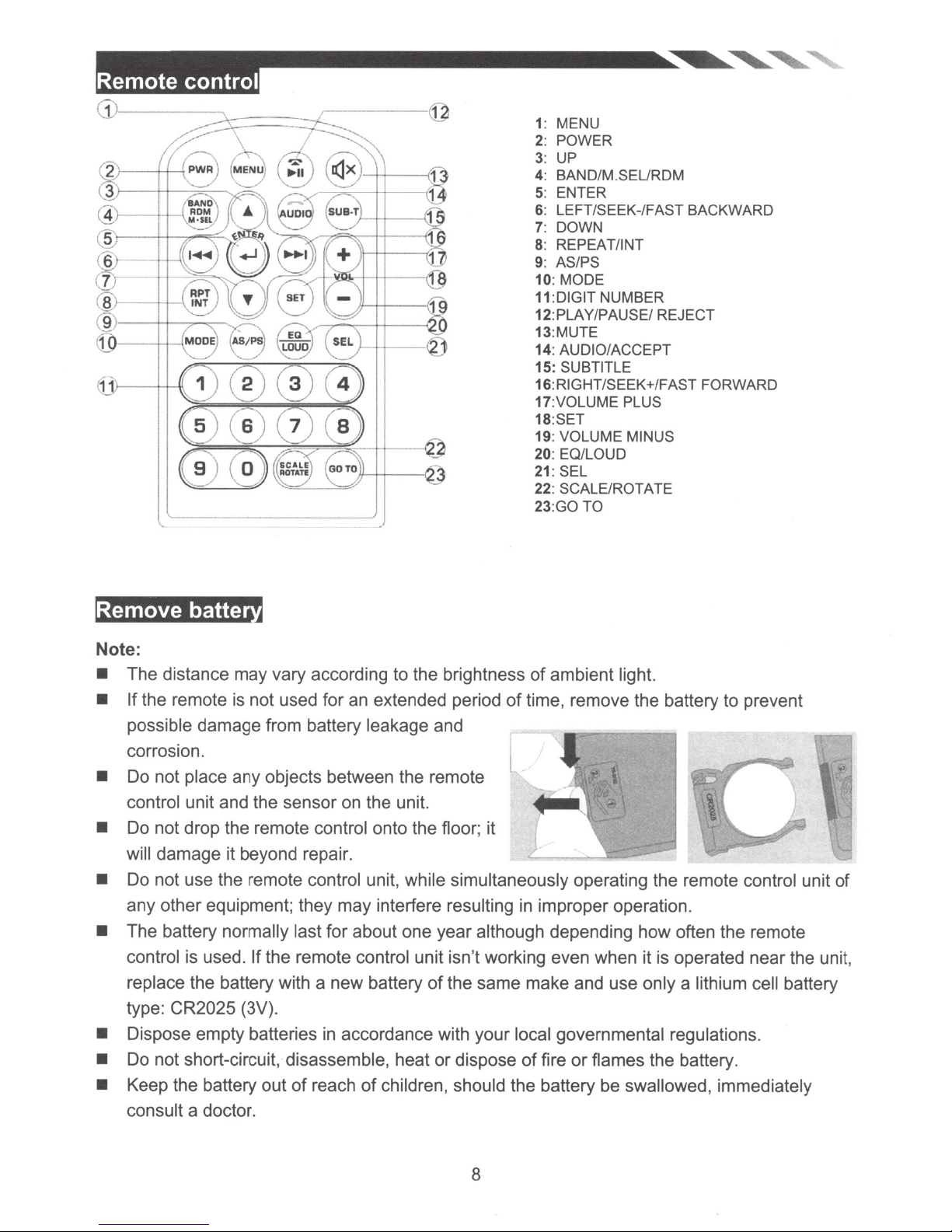
1: MENU
2: POWER
3: UP
4: BAND/M.SEURDM
5: ENTER
6:
LEFT/SEEK-/FAST BACKWARD
7: DOWN
8: REPEAT/INT
9:
AS/PS
10:
MODE
11:DIGIT NUMBER
12:PLAY/PAUSE/ REJECT
13
:MUTE
14: AUDIO/ACCEPT
15: SUBTITLE
16
:RIGHT/SEEK+/FAST FORWARD
17:VOLUME PLUS
18:SET
19: VOLUME MINUS
20: EO/LOUD
21
: SEL
22: SCALE/ROT ATE
23:GO TO
Remove batte
Note:
• The distance may vary according to the brightness
If
the remote is not used for an extended period
•
possible damage from battery leakage and
corrosion .
• Do not place any objects between the remote
on
control unit and the sensor
• Do not drop the remote control onto the floor;
will damage it beyond repair.
• Do not use the remote control unit, while simultaneously operating the remote control unit
any other equipment; they
• The battery normally last for about one year although depending how often the remote
If
control is used.
replace the battery with a new battery
type: CR2025 (3V).
• Dispose empty batteries in accordance with your local governmental regulations.
• Do not short-circuit, disassemble , heat or dispose
• Keep the battery
consult a doctor.
the remote control unit isn't working even when it is operated near the unit,
out
of
reach
the unit.
may
interfere resulting in improper operation.
of
the same make and use only a lithium cell battery
of
children, should the battery be swallowed, immediately
of
ambient light.
of
time, remove the battery to prevent
it
of
fire
or
flames the battery.
of
8
 Loading...