

Soundstream SA 164, SA 80 Owner's Manual And Installation Manual

SOUNDSTREAl’vl@
-
SA80
SA 164
Power Amplifiers
OWNERS MANUAL AND
INSTALLATION GUIDE
SOUNDSTREAM’
TECHNOLOGIES
CONGRA TULA TIONS!
You now own a Soundstream Amplifier, the result of a unique design and
engineering philosophy.
To maximize the performance of your system, we recommend that you
thoroughly acquaint yourself with its capabilities and features. Please retain this
manual and your sales and installation receipts for future reference.
Soundstream amplifiers are the result of American craftsmanship and the
highest quality control standards, and when properly installed, will provide you
with many years of listening pleasure. Please record the following information
which will help protect your investment should your amplifier ever need
replacement or service..
Serial #
Dealer’s Name
Date of Purchase
Installation Shop
Installation Date
CAUTION!
Prolonged listening at high levels
may
result in hearing loss.
Even
though your new Soundstream amplifier sounds better than
anything you’ve ever heard, exercise caution to prevent heating
damage.
2
TABLE OF CONTENTS
SA*80
Diagram..
...............................................................
4 - 5
SAmI
Diagram
...............................................................
6-7
Features
.......
..’
.....................................................................
8
Crossover Modes and Adjustments..
....................................
9
Selecting
Input Modes..
......................................................
10
Wiring & Wiring Diagram
.............................................
II-12
Installation and
Mounting.. ..................................................
13
Level Setting
.......................................................................
14
Sample Systems
.........................................................
15-
17
Protection Circuitry & Troubleshooting
...............................
18
Service..
.............................................................................
19
Specifications
.....................................................................
19
3
0
0
Side view
IO
\
MAlN
FUSE
uL
u
Underside View
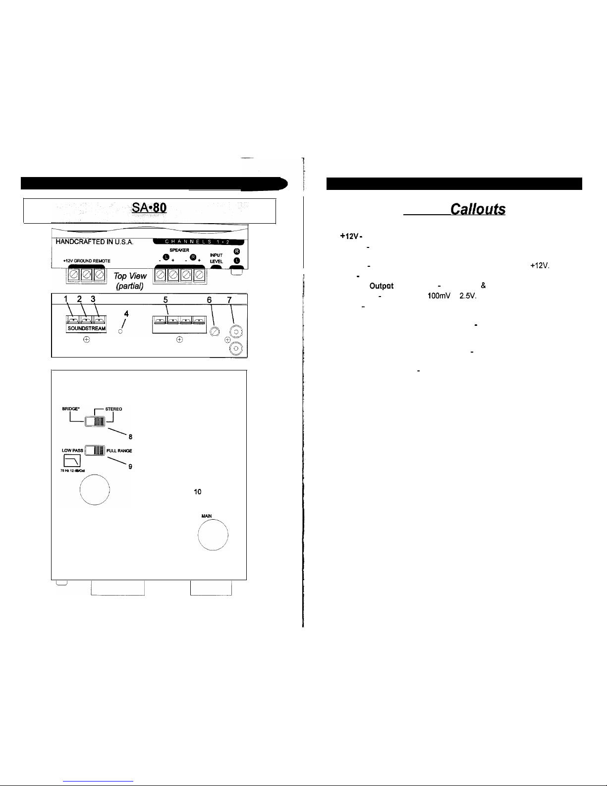
4
1.
2.
3.
4.
5.
6.
7.
6.
9.
Key to
Callouts
+12V - Connected to fuse or circuit breaker, then battery’s positive post.
Ground - Main ground connection. Bolt to a clean chassis ground in the
vehicle.
Remote - Remote turn-on input from the head unit. Accepts
+12V.
LED - Indicates amplifier power on.
Speaker
Outpot
Connections - Channels 1 & 2
Input Level - Variable from
IOOmV
to
23.
Inputs - Right and left channel inputs; only right channel input used in
“Mono” mode.
[underside] Stereo/Bridged Mono Switch - Select “Mono” for bridged
operation (use only right channel input or stereo position for 2-channel
Stereo or Mixed Mono operation).
[underside] Amplifier Crossover Switch - Select low pass or full range
operation.
10. [underside] Main Fuse - Main power supply fuse. Replace only with same
fuse value.
SA.164
I
-
/
I
i HANDCRAFTED IN U.S.A.
Top View (partial)
67 8
9 10
Side
View
.f-Y
i
/
/\
ii’
CHANNELS 1 & 2
LOW
PAS m FULL
RANGE
.14
15
\
MAIN FUSE
I-
i
11
Underside View
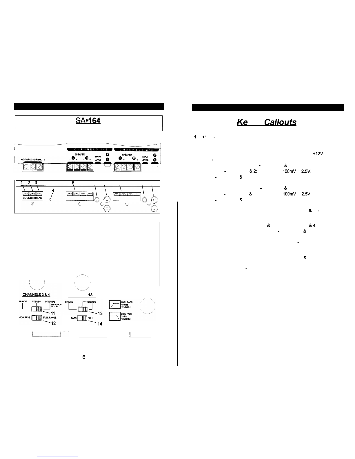
6
1.
2.
3.
4.
5.
6.
7.
6.
9.
10.
11.
12.
13.
14.
15.
v to
Callouts
+I
2V - Connected to fuse or circuit breaker, then battery’s positive post.
Ground - Main ground connection. Bolt to a clean chassis ground in the
vehicle.
Remote - Remote turn-on input from the head unit. Accepts
+12V.
LED - Indicates amplifier power on.
Speaker Output Connections - Channels 1 & 2
Input Level - Channels 1
812;
variable from
IOOmV
to
2.5’.
Inputs - Channels 1 & 2; right and lefl channel inputs; only right channel
input used in “Mono” mode.
Speaker Output Connections - Channels 3 & 4
Input Level - Channels 3 & 4; variable from
IOOmV
to
2.5V
Inputs - Channels 3 & 4; right and lefl channel inputs; only right channel
input used in “Mono” mode
[underside] Stereo/Bridged Mono/Internal Switch (ch 3 & 4) - Select
“Mono” for bridged operation (use only right channel input or stereo
position for 2-channel Stereo or Mixed Mono operation). “Internal” allows
you to use the inputs to channels 1 & 2 to feed channels 3
814.
[underside] Amplifier Crossover Switch - Channels 3 & 4; select high
pass or full range operation.
[underside] Stereo/Bridged Mono/Remote Switch - Channels 1 8 2;
select “Mono” for bridged operation (use only right channel input or stereo
position for 2-channel Stereo or Mixed Mono operation.
[underside] Amplifier Crossover Switch - Channels 1 & 2; select low
pass or full range operation.
[underside] Main Fuse - Main power supply fuse. Replace only with
same fuse value.
 Loading...