

Soundstream SA.120, SA-244, SA-245 Owner's Manual And Installation Manual
S@UNDSTREYW’@
_
SAd20
SAe244
SAa
245
Power Amplifiers
OWNERS MANUAL AND
INSTALLATION GUIDE
I
SWNDSTREAM’
TECHNOLOGiES
TABLE OF CONTENTS
SA.120
Diagram.. ........................................................
4 - 5
SA.244 Diagram..
.........................................................
6 -7
SA*245
Diagram
..........................................................
8-9
Features
.........................................................................
.I0
Crossover Modes and Adjustments..
.......................
11- 12
Selecting Input Modes..
..................................................
.I3
Wiring & Wiring
Diagram..
.......................................
14 - 15
Installation and Mounting..
..............................................
.I6
Level Setting
..................................................................
.17
Sample Systems .....................................................
18 - 21
Protection Circuitry & Troubleshooting
...........................
.22
Service
..........................................................................
..2
3
Specifications..
...............................................................
.23
2
CCMGRA
TULA TIUMS.’
You now own a Soundstream Amplifier, the result of a unique design and
engineering philosophy.
To maximize the performance of your system, we recommend that you
thoroughly acquaint yourself with its capabilities and features. Please retain this
manual and your sales and installation receipts for future reference.
Soundstream
am’plifiers
are the result of American craftsmanship and the
highest quality control standards, and when properly installed,
will
provide you
with many years of listening pleasure. Please record the following information
which will help protect your investment should your amplifier ever need
replacement or service..
Serial
#
Dealer’s Name
Date of Purchase
Installation Shop
Installation Date
3
Top view
(partial)
1 2 3
5
6 7 6 9
Side view
I-
-
I
I
I
I II
1 I
1.
2.
3.
4.
5.
6.
7.
6.
9.
16.
11.
12.
13.
14.
15.
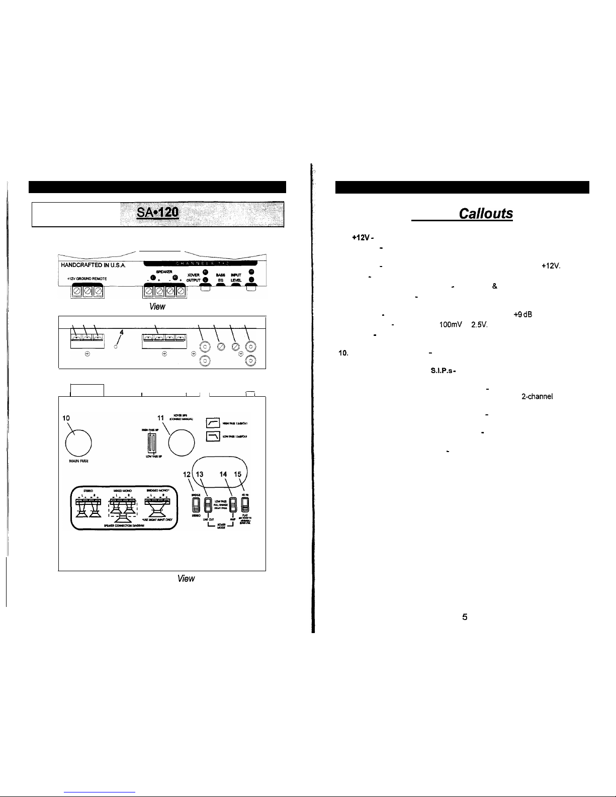
Key to
Callouts
+12V
- Connected to fuse or circuit breaker, then battery’s positive post.
Ground - Main ground connection. Bolt to a clean chassis ground in the
vehicle.
Remote - Remote turn-on input from the head unit. Accepts
+12V.
LED - Indicates amplifier power on.
Speaker Output Connections - Channels 1 & 2
Crossover Output - Low level output to auxiliary amplifier for high or low
pass.
Bass EQ - Adjustable bass equalization circuit, Cl to +9 dB boost at 45 Hz.
Input Level - Variable from
100mV
to
2.5V.
Inputs - Right and left channel inputs; only right channel input used in
“Mono” mode.
[underside] Main Fuse - Main power supply fuse. Replace only with
same fuse value.
[underside] Crossover
S.1.P.s -
Crossover frequency settings for
amplifier and crossover line outputs.
[underside] Stereo/Bridged Mono Switch - Select “Mono” for bridged
operation (use only right channel input) or “Stereo” for 2-channel Stereo or
Mixed Mono operation; See crossover section for more details.
[underside] Line Out Crossover Switch - Select high pass, low pass, or
full range operation of crossover outputs.
[underside] Amplifier Crossover Switch - Select high pass, low pass, or
full range operation of amplifier.
[underside] Bass EQ Switch - On/Off switch for bass equalization circuit.
Underside view
4
5
Ii
li
io
2;
2i
2i
Underside View
6
1.
2.
3.
4.
5.
6.
7.
8.
9.
IO.
11,
12.
13.
14.
15.
16.
17.
18.
19.
20.
21.
22.
23.
24
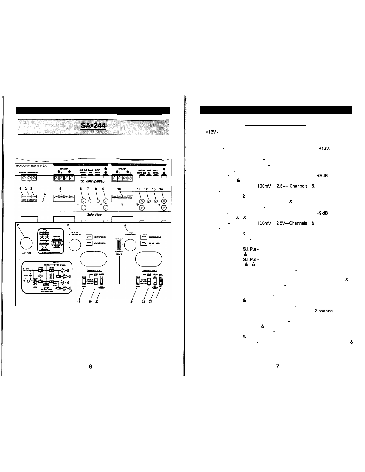
Key to Cailouts
+12V -
Connected to fuse or circuit breaker, then battery’s positive post.
Ground - Main ground connection. Bolt to a clean chassis ground in the
vehicle.
Remote - Remote turn-on input from the head unit. Accepts
+lZV.
LED - Indicates amplifier power on.
Speaker Output Connections - Channels 1 & 2
High Pass Crossover Output - Low level high pass outputs to auxiliary
amplifier.
.
Bass EQ - Adjustable bass equalization circuit, 0 to +9 dB boost at 45
Hz-Channels 1 & 2.
Input Level - Variable from
IOOmV
to
2.5V-Channels
1 & 2.
Inputs - Right and left channel inputs; only right channel input used in “Mono”
mode-Channels 1 & 2.
Speaker Output Connections - Channels 3 & 4
Low Pass Crossover Output - Low level low pass output to auxiliary amplifier.
Bass EQ - Adjustable bass equalization circuit, 0 to +9 dB boost at 45
Hz-Channels 3 8 4 & low pass output.
Input Level - Variable from
1OOmV
to
2.5V-Channels
3 & 4.
Inputs - Right and left channel inputs; only right channel input used in “Mono”
mode-Channels 3 & 4.
[underside] Main Fuse - Main power supply fuse. Replace only with same fuse
value.
[underside] Xover
S.1.P.s -
Crossover frequency settings for amplifier and
outputs-channels 1 & 2 8 high pass and low pass outputs.
[underside] Xover
S.1.P.s -
Crossover frequency settings for amplifier and
outputs-Channels 3 & 4 & low pass outputs.
[underside] Stereo/Bridged Mono Switch - Select “Mono” for bridged
operation (use only right channel input) or “Stereo” for 2-channel Stereo or
Mixed Mono operation; See crossover section for more details-Channels 1 & 2.
[underside] Amplifier Crossover Switch - Select high pass, low pass, or full
range operation-Channels 1 & 2.
[underside] Bass EQ Switch - On/Off switch for bass equalization
circuit-Channels 1 & 2.
[underside] Stereo/Bridged Mono Switch - Select “Mono” for bridged
operation (use only right channel input) or “Stereo” for 2-channel Stereo or
Mixed Mono operation; See crossover section for more details.
[underside] Amplifier Crossover Switch - Select high pass, low pass, or full
range operation-Channels 3 & 4.
[underside] Bass EQ Switch
-
On/Off switch for bass equalization
circuit-Channels 3 & 4.
[underside] Input Select - Selectable inputs from internal (from channels 1
&
2) or external.
7
 Loading...