

Soundstream Rubicon Balanced X.0 User Manual
SWNDSTRS
T
E
C
H
N
0
L
0
G
I E
S
WWW.SOUNDSTREAM.COM
Folsom l California 95630 USA
ph 916.351.1288 . fax 916.351.0414
rev
A - &/13/98
20
SOUNDSTREA,M
T
E
C H N
0
L
0
G
1
E
S
RUBICON
BALANCED X.0
2=WAY/3=WAY
ELECTRONIC
CROSSOVER
OWNER’S MANUAL
AND
INSTALLATION GUIDE
CONGRATWAT/O/VS!
You now own
the
BALANCED X.0
crossover,
the product of an uncom-
promising design and engineering philosophy.
To maximize the performance of your system, we recommend that
you
thoroughly acquaint yourself with its capabilities and features. Please retain this manual and your sales and installation receipts for future reference.
Soundstream products are the result of American craftsmanship and the
highest quality control standards, and when properly installed, will provide
you with many years of listening pleasure. Should your crossover ever
need service or replacement due to theft, please record the following information, which
will help protect your investment.
Model and Serial
#
Dealer’s Name
Date of Purchase
Installation Shop
Installation Date
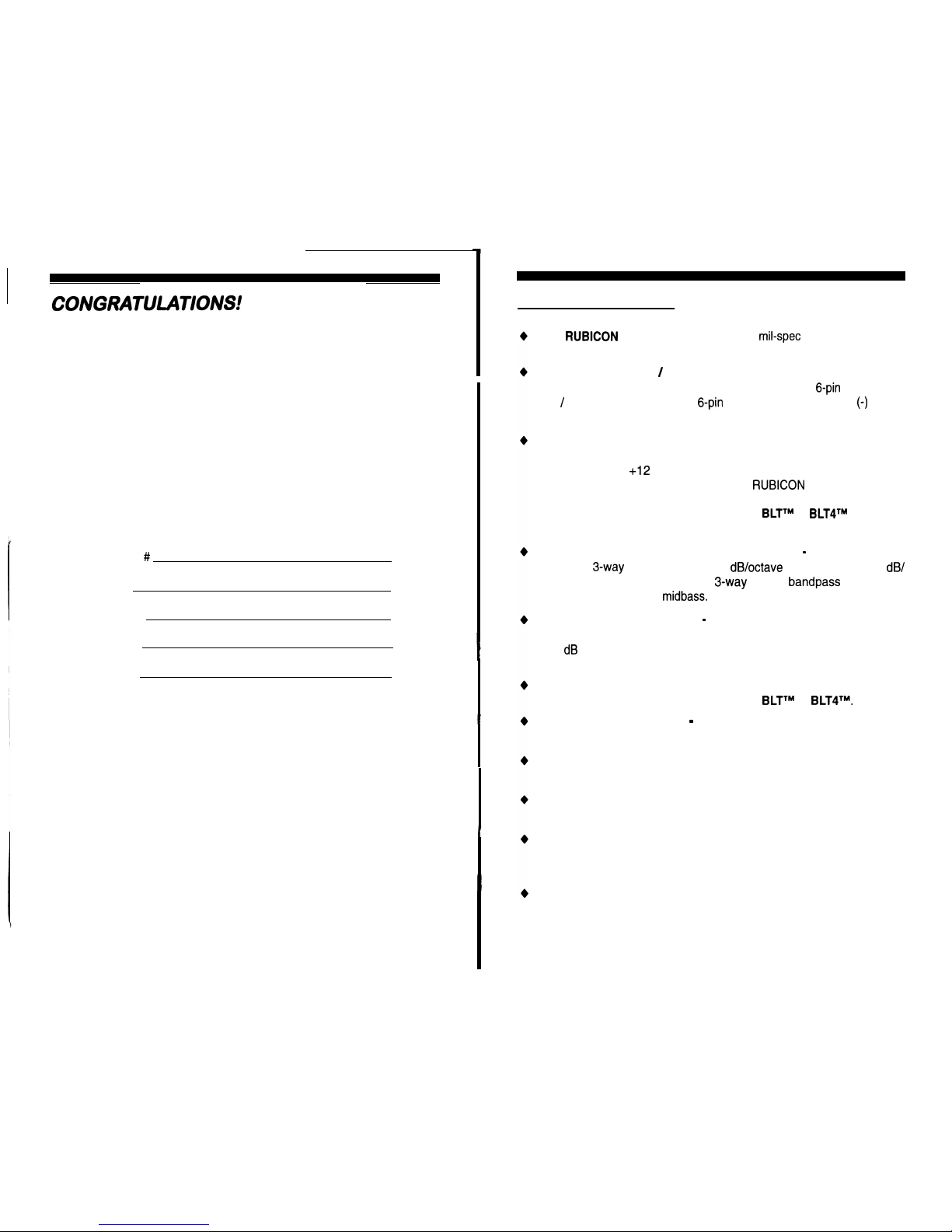
DESIGN FEATURES
Pure
RUBICON
Design Quality
including
mil-spec
glass epoxy circuit
boards and 1% tolerance components.
True Balanced Input / Output
for professional-quality performance
and noise cancellation, utilizing industry compatible
6-pin
Mini-Din in-
put / output connectors. The
6-pin
din plug carries (+) and
(-)
signal
information for left and right channels (front and rear) and audio ground.
Phantom Powered or Standard Power Connections:
The BAL-
ANCED X.0 can be powered conventionally by the connecting barrier
strip to remote,
+I2
V and ground. Or, it can receive power (and
remote) from the balanced input of the
RUBICON
amplifier it is connected to (phantom power). The BALANCED X.0 also passes this
phantom power to drive the Soundstream
BLTTM
or
BLT41M
(Balanced
Line Transmitter) at the head unit.
Staggered Asymmetrical Electronic Crossover - Continuously vari-
able 2 or
3-way
crossover with 12
dB/octave
high pass and 24
dB/
octave subwoofer low pass.
In
3-way
mode,
bandpass
can be se-
lected for midrange or
midbass.
Rear Channel De-emphasis -A circuit based on theater surround
technology in which rear fill information is rolled off at 6 dB/octave with
a -3 dB point at 7,000 Hz to provide a more realistic listening experience (in 5 channel mode only).
Direct Input
switches allow the input stage of the BALANCED X.0 to
be completely bypassed for use with the
BLTTM
or
BLT4Y
Input Overload Indicators -Indicates the signal input level or input
gain level is too high.
Selectable Subwoofer Fading
allows the subwoofer input to come
from the front or the rear balanced input, or both.
Multiple Subwoofer Output Connectors
allows easy connection of
multiple subwoofer amplifiers.
Subsonic Filter (Subchannels)
An adjustable subsonic filter which
protects woofers from potentially harmful low frequency information
and maximizes output in a usable and adjustable range.
Remote In and Out (External Power Supply Only)
Helps eliminate
turn on and off pops by turning the X.0 on before the amplifiers and
turning the X.0 off after the amplifiers.
3
1
2 3
4
5
6
7 8
9 10
11
1 1
1
1 1
\
1
\
\
\I \\
\
\ \
\
\
\\ \ \
HIGH PASS
INPUT MONO
MONO
INPUT
HIGH PASS HIGH PASS
OUTFUT
OUT N
I
GND POWER
OUTFIJT
2
OUTFUT
OUTFWT
REMOTE
3 WAY
MNAANDPASS
0000
-REAR
-
-SUBWOOFER -
-
FRONT-
BALANCED X.0
2-WAY/3-WAY
ELECTRONIC CROSSOVER
Handcrafted in
LEA,
12 13 14 15 16
13
19 20
21
\\ \ \
\
'i
\ \ \
\
OIglCHI
OUltNCE
0
INPUT 5V
VARI
ON OFF
IN
OUT
IN
OlJT
INPUT ON OFF5v
VARI
O’&
RI
OAD
INPI
IT
2w 3w
SUB
FCJWER
RE ARF
IL1
SUB
LEVEL
3MRLOAD
SUB
INPUT
CONTROL DE-EMPHASIS SONIC
CONTROL LEVEL
-
REAR
-
- SUBWOOFER-
FRONT
INPUT LEVEL
HIGHPASS
SUBSONIC LOW PASS
INPUT LEVEL
SAT/BANDPASS FRE&l
MULTI
HIGH PASS
TOP VIEW
22
23
24 25 26
27 28
29 30
.
*
. . .
L L
.
.
;@)
@; ;;bo
1 1
;Q’
;Q
L
R
A~2~~~~ob?
20 50.
2.00
FREQ
27 FREQ "
60 FREQ240 L
R
FREQ FREQ
INPUT LEVEL
HIGHPASS SUBSONIC
LOW PASS
INPUT LEVEL
SAT/BANDPASS
FREQ MULTI HIGH PASS
FRONT VIEW
1.
2.
3.
4.
5.
6.
7.
a.
9.
10.
11.
12.
13.
14.
15.
16.
17.
18.
19.
20.
21.
22.
23.
24.
25.
26.
27.
28.
29.
30.
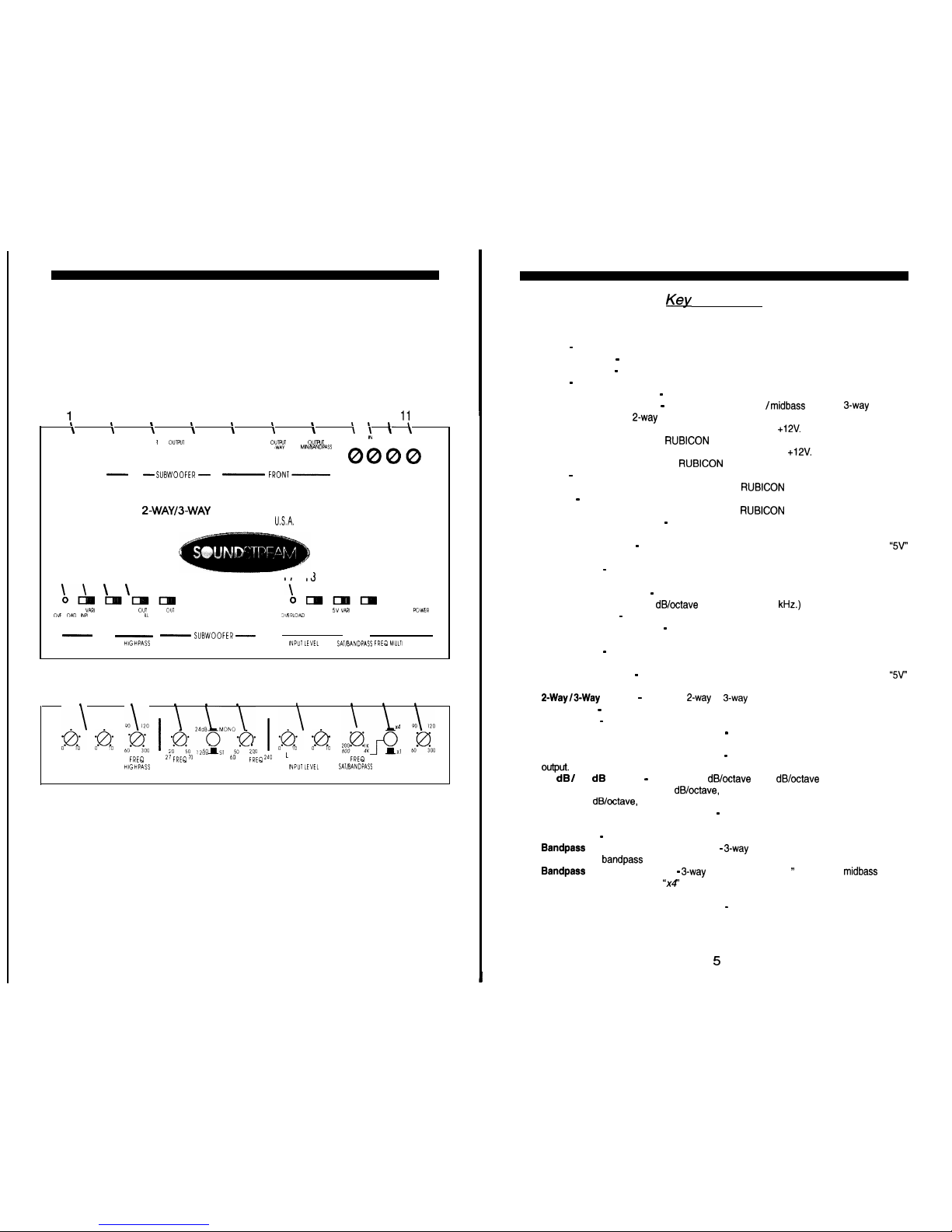
Key to Cal/outs
High Pass Rear Output-
Balanced output to the amplifier driving the rear satellite speak-
ers.
Input
-
Balanced rear inputs (left and right).
Mono 1 Output
-
Balanced subwoofer output (Subwoofer Left output in
Stereo mode).
Mono 2 Output
-
Balanced subwoofer output (Subwoofer Right
output in Stereo mode).
Input
-
Balanced front inputs (left and right).
High Pass Front Output
-
Balanced front tweeter/satellite output in 3-way mode.
High Pass Front Output
-
Balanced front midrange / midbass output in
3-way
mode, or
front satellite output in
2-way
mode.
REM Out-
Remote turn-on output to an amplifier. Passes
+12V.
(Except when powered via
the Mini-Din connector from a
RUBICON
amplifier.)
REM In-
Remote turn-on input from the head unit. Accepts
+12V.
(Except when powered
via the Mini-Din connector from a
RUBICON
amplifier.)
GND
-
Main ground connection. Bolt to a clean chassis ground in the vehicle. (Except
when powered via the Mini-Din connector from a
RUBICON
amplifier.)
Power
-
Connected to a fuse or circuit breaker, then to the battery’s positive post.
(Except
when powered via the Mini-Din connector from a
RUBICON
amplifier.)
Input Overload Indicator
-
Rear channels input; Indicates the signal input level or input
gain level is too high.
Input Level Switch
-
Rear channels input; Select “VARY to use the gain controls, or
“W”
to bypass the rear input controls of the BALANCED X.0.
Sub Control
-
Rear channels input; Select “IN” to send low frequency information from the
rear channels input to the subwoofer mono output.
Rear Fill De-Emphasis
-
Select “IN” to include de-emphasis in the rear channels high pass
output. (De-emphasis is a 6
dB/octave
low pass filter at 7 kHz.)
Subsonic Filter
-
Select “IN” to include a subsonic filter in the subwoofer mono output.
Input Overload Indicator
-
Front channels input; Indicates the signal input level or input
gain level is too high.
Sub Control
-
Front channels input; Select “IN” to send low frequency information from the
front channels input to the subwoofer mono output.
Input Level Switch
-
Front channels input; Select “VARI” to use the gain controls, or “5V”
to bypass the front input controls of the BALANCED X.0.
2-Way/30Way
Switch
-
Selectable 2-way or 3-way crossover output for the front channels.
Power LED
-
Indicates the unit is “ON”.
Input Level
-
Rear channels; Independent left and right channel input level controls.
High Pass Crossover Adjustment Pot
-
Crossover frequency setting for the high pass
filter on the rear left and right high pass outputs.
Subsonic Frequency Adjustment Pot
-
Subsonic frequency setting for the subwoofer
OUtpUt.
12 dB / 24 dB Button
-
Selectable 12 dB/octave or 24 dB/octave low pass filter for the
subwoofer output. (Note: For 12 dB/octave, use the grey markings on the subwoofer controls. For 24 dB/octave, use the white markings on the subwoofer controls.)
Low Pass Crossover Adjustment Pot
-
Crossover frequency setting for the low pass filter
for the subwoofer output.
Input Level
-
Front channels; Independent left and right channel input level controls.
Bandpass
Crossover Adjustment Pot
-
3-way mode only; Crossover frequency setting
for the internal
bandpass
filter for the front channels.
Bandpass
Crossover Switch
-
3-way mode only; Select “xl ” for use with midbass drivers
and satellite speakers. Select “x4” for use with midrange drivers and tweeters, and use the
markings written in italics.
High Pass Crossover Adjustment Pot
-
Crossover frequency setting for the high pass
filter on the front left and right high pass outputs.
5
 Loading...